EP3945533B1 - Dispositif de filtrage inductif a limitation d'echauffement - Google Patents
Dispositif de filtrage inductif a limitation d'echauffement Download PDFInfo
- Publication number
- EP3945533B1 EP3945533B1 EP21187083.7A EP21187083A EP3945533B1 EP 3945533 B1 EP3945533 B1 EP 3945533B1 EP 21187083 A EP21187083 A EP 21187083A EP 3945533 B1 EP3945533 B1 EP 3945533B1
- Authority
- EP
- European Patent Office
- Prior art keywords
- magnetic core
- screen
- cable
- filtering device
- around
- Prior art date
- Legal status (The legal status is an assumption and is not a legal conclusion. Google has not performed a legal analysis and makes no representation as to the accuracy of the status listed.)
- Active
Links
Images
Classifications
-
- H—ELECTRICITY
- H01—ELECTRIC ELEMENTS
- H01F—MAGNETS; INDUCTANCES; TRANSFORMERS; SELECTION OF MATERIALS FOR THEIR MAGNETIC PROPERTIES
- H01F17/00—Fixed inductances of the signal type
- H01F17/04—Fixed inductances of the signal type with magnetic core
- H01F17/06—Fixed inductances of the signal type with magnetic core with core substantially closed in itself, e.g. toroid
- H01F17/062—Toroidal core with turns of coil around it
-
- H—ELECTRICITY
- H01—ELECTRIC ELEMENTS
- H01F—MAGNETS; INDUCTANCES; TRANSFORMERS; SELECTION OF MATERIALS FOR THEIR MAGNETIC PROPERTIES
- H01F27/00—Details of transformers or inductances, in general
- H01F27/08—Cooling; Ventilating
-
- H—ELECTRICITY
- H01—ELECTRIC ELEMENTS
- H01F—MAGNETS; INDUCTANCES; TRANSFORMERS; SELECTION OF MATERIALS FOR THEIR MAGNETIC PROPERTIES
- H01F17/00—Fixed inductances of the signal type
- H01F17/04—Fixed inductances of the signal type with magnetic core
- H01F17/045—Fixed inductances of the signal type with magnetic core with core of cylindric geometry and coil wound along its longitudinal axis, i.e. rod or drum core
-
- H—ELECTRICITY
- H01—ELECTRIC ELEMENTS
- H01F—MAGNETS; INDUCTANCES; TRANSFORMERS; SELECTION OF MATERIALS FOR THEIR MAGNETIC PROPERTIES
- H01F27/00—Details of transformers or inductances, in general
- H01F27/24—Magnetic cores
-
- H—ELECTRICITY
- H01—ELECTRIC ELEMENTS
- H01F—MAGNETS; INDUCTANCES; TRANSFORMERS; SELECTION OF MATERIALS FOR THEIR MAGNETIC PROPERTIES
- H01F27/00—Details of transformers or inductances, in general
- H01F27/28—Coils; Windings; Conductive connections
- H01F27/2823—Wires
-
- H—ELECTRICITY
- H01—ELECTRIC ELEMENTS
- H01F—MAGNETS; INDUCTANCES; TRANSFORMERS; SELECTION OF MATERIALS FOR THEIR MAGNETIC PROPERTIES
- H01F27/00—Details of transformers or inductances, in general
- H01F27/28—Coils; Windings; Conductive connections
- H01F27/288—Shielding
- H01F27/2885—Shielding with shields or electrodes
-
- H—ELECTRICITY
- H01—ELECTRIC ELEMENTS
- H01F—MAGNETS; INDUCTANCES; TRANSFORMERS; SELECTION OF MATERIALS FOR THEIR MAGNETIC PROPERTIES
- H01F27/00—Details of transformers or inductances, in general
- H01F27/34—Special means for preventing or reducing unwanted electric or magnetic effects, e.g. no-load losses, reactive currents, harmonics, oscillations, leakage fields
- H01F27/36—Electric or magnetic shields or screens
- H01F27/363—Electric or magnetic shields or screens made of electrically conductive material
-
- H—ELECTRICITY
- H01—ELECTRIC ELEMENTS
- H01F—MAGNETS; INDUCTANCES; TRANSFORMERS; SELECTION OF MATERIALS FOR THEIR MAGNETIC PROPERTIES
- H01F17/00—Fixed inductances of the signal type
- H01F17/04—Fixed inductances of the signal type with magnetic core
- H01F17/06—Fixed inductances of the signal type with magnetic core with core substantially closed in itself, e.g. toroid
- H01F2017/065—Core mounted around conductor to absorb noise, e.g. EMI filter
-
- H—ELECTRICITY
- H01—ELECTRIC ELEMENTS
- H01F—MAGNETS; INDUCTANCES; TRANSFORMERS; SELECTION OF MATERIALS FOR THEIR MAGNETIC PROPERTIES
- H01F27/00—Details of transformers or inductances, in general
- H01F27/34—Special means for preventing or reducing unwanted electric or magnetic effects, e.g. no-load losses, reactive currents, harmonics, oscillations, leakage fields
- H01F2027/348—Preventing eddy currents
Definitions
- the invention relates to an inductive filtering device.
- This type of filtering is commonly used to reduce possible disturbances present on a signal carried on an electric cable.
- the device is then placed in series on the cable.
- the invention finds particular utility in the aeronautical field where the current trend is to increase the number of electrical equipment and therefore the number of filtering devices associated with the equipment. In this field, the reduction of on-board mass is a recurring problem that arises.
- the invention proposes to reduce the mass of the filtering devices.
- a filtering device can be formed by an inductor connected in series on an electrical conductor.
- the value of the impedance of an inductor is proportional to the frequency of the current flowing through it.
- An inductor is therefore well suited to filtering the high-frequency components of the current flowing in the electrical conductor.
- Inductance can be achieved by means of an electrical conductor wound around a magnetic core to channel the magnetic flux induced by the current flowing in the electrical conductor.
- a closed magnetic core In order to optimize the circulation of the magnetic flux, it is possible to implement a closed magnetic core without an air gap.
- This type of core is called by many manufacturers: "toroidal core". It is formed around a central recess. The qualification of toroidal for the magnetic core goes well beyond the mathematical definition of a torus. In particular, there are so-called toroidal magnetic cores with circular, rectangular sections, etc. Inductance is achieved by winding an electrical conductor around the magnetic core, crossing the central recess in order to form one or more turns.
- the harmonics and more generally the high frequency components when filtering harmonics of a current whose fundamental component is at low frequency, the harmonics and more generally the high frequency components, superimposing themselves on the fundamental component of the current, generate significant induced electric currents in the magnetic core.
- the materials of the Magnetic cores are chosen for their magnetic properties, particularly for their permeability, they are also conductors of electricity. This electrical property allows the generation of induced currents. The higher the frequency of the current flowing in the conductor, the higher the induced current.
- the heat produced in the magnetic core can be evacuated by increasing the volume of the magnetic core in order to increase its contact surface with the ambient air. It is also possible to provide a heat sink fixed to the core. Whatever the solution chosen to evacuate the heat, this leads to an increase in the mass and volume of the inductance.
- a first aim of the invention is to reduce the mass and volume of an inductance using a magnetic core. This aim is achieved by limiting the occurrence of high-frequency current in the magnetic core around which the conductor of the inductance is surrounded.
- a conductive screen is arranged between the inductance conductor and the magnetic core.
- This screen has the function of displacing the generation of induced currents looped from the magnetic core to the screen.
- the induced currents are opposite to those flowing in the conductor.
- the magnetic core is subjected to two opposing currents, which tends to reduce the magnetic flux and therefore the induced currents that can flow in the magnetic core.
- the presence of the screen makes it possible to very significantly reduce the appearance of induced currents in the magnetic core and therefore its heating.
- the document US 2016/365192 A1 discloses a noise filter comprising a ring-shaped magnetic core, a winding around the magnetic core, and a ground terminal disposed between the magnetic core and the winding, the ground terminal being connected to a ground.
- the ground terminal comprises a conductive portion that surrounds at least a portion of the outer periphery of the magnetic core.
- the document US 2001/050605 A1 discloses a noise filtering device comprising a coaxial cable wrapped around a rod-shaped ferrite core.
- the electric cable extends along an axis and the screen is arranged around the electric cable in a coaxial manner.
- the magnetic core may be cylindrical in shape extending around an axis
- the screen advantageously protrudes from the magnetic core beyond the turn(s) formed around the magnetic core.
- the protrusion is advantageously at least equal to a larger external dimension along the axis of the magnetic core.
- the cable can be wound several times around the magnetic core forming several turns around the magnetic core.
- the screen is arranged on at least one face of the magnetic core.
- the screen may comprise several parts, each part being arranged so as to cover one of the faces of the magnetic core.
- the screen may comprise two shells fitting into each other, the two shells being electrically insulated from each other.
- the magnetic core may have a central recess and the electrical cable may be wound around the magnetic core passing through the central recess.
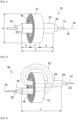
- FIG. 1 represents an inductive filtering device 10 comprising a magnetic core 12 and an electric cable 14.
- the inductive filtering device 10 forms an inductance.
- the magnetic core 12 is formed around a central recess 16.
- the magnetic core 12 is tubular in shape extending around an axis 18.
- the central recess 16 develops around the axis 18.
- the magnetic core 12 is closed and for example without an air gap.
- the magnetic core 12 has a circular section perpendicular to the axis 18. Other sections are possible within the scope of the invention, for example a rectangular, triangular section, etc.
- the circular section is well suited to the passage of an electric cable 14 also with a circular section passing through the central recess only once.
- the cable 14 extends along an axis 19.
- the axes 18 of the magnetic core 12 and 19 of the cable 14 are substantially the same, with the functional clearance between the cable 14 and the central recess 16.
- the electric cable 14 can pass through the central recess 16 several times. It may then be advantageous to arrange the different passages in the central recess 16 to occupy a section different from a circular section.
- the shape of the magnetic core 12 may also be guided by the environment of the device 10. It may be easier to store a device 10 whose magnetic core 12 has a rectangular section.
- This type of closed magnetic core without an air gap is usually called "toroidal" by many manufacturers. This qualifier goes well beyond the shape of a torus as defined mathematically. We find in particular so-called toroidal magnetic cores with circular, rectangular section, etc. The absence of an air gap makes it possible to keep the magnetic field developing in the magnetic core 12 only in the material of the magnetic core without being disturbed by an air gap.
- the device 10 comprises an electrically conductive screen 20, arranged between the magnetic core 12 and the electric cable 14.
- the screen 20 is electrically insulated from the electric cable 14 and from the magnetic core 12.
- the screen 20 is arranged around the electric cable 14.
- the screen 20 is coaxial with the cable 14.
- An electrical insulator 22 is arranged between the cable 14 and the screen 20.
- the electrical insulator 22 may be an outer sheath of the cable 14.
- Another electrical insulator 24 is arranged between the screen 20 and the magnetic core 12.
- the insulator 24 covers the screen 20.
- the insulator 24 can cover the magnetic core 12 and in particular the internal face of the central recess 16.
- the arrangement of the screen 20 between the cable 14 and the magnetic core 12 allows the circulation of currents in the screen 20. These currents are generated by electromagnetic induction formed by the current flowing in the cable 14.
- the device 10 allows inductive filtering of a current flowing in the cable 14.
- This current may be noisy. More precisely, the current flowing in the cable 14 comprises a fundamental frequency and higher frequencies whose amplitude is sought to be reduced by means of the device 10.
- the fundamental frequency is zero.
- the higher frequencies are formed of all alternating components superimposed on the direct component of the current or on the fundamental alternating component in the case of an alternating current flowing in the cable 14. These alternating components of frequency higher than the fundamental frequency may be due to the production of the direct current by means of a rectifier. Indeed, traces of frequencies present upstream of the rectifier are found superimposed on the direct current.
- Undesirable AC components may also be due to current rejections emitted by loads supplied by the cable 14 or to electromagnetic disturbances that the cable 14 may undergo.
- screen 20 we are interested in mainly to the generation of currents induced by the undesirable alternating components of the current flowing in the cable 14.
- the thickness ⁇ of the screen 20 must have at least the thickness of the skin in which the current flows at the given frequency. Below this thickness, the filtering of the given frequency remains, but with less efficiency. It is possible to take a safety margin in determining the thickness ⁇ of the screen 20 by choosing a thickness at least equal to two or three times the thickness of the skin in which the current flows at the given frequency.
- the screen 20 has a finite length L along the axis 19 of the cable 14, advantageously greater than the length l of the magnetic core 12 along its axis 18.
- the fact that the length L of the screen 20 is finite makes it possible to avoid the circulation in the screen 20 of current in a direction parallel to the axis 19 of the cable 14. Such currents are not desirable because they would oppose the passage of the fundamental frequency in the cable 14 by forming a transformer.
- the passage of the cable 14 through the central recess 16 is assimilated to a turn surrounding the magnetic core 2. More precisely, when a current flows in the cable 14, the latter forms a closed circuit with at least one generator and one load.
- This closed circuit forms a turn around a section of the magnetic core 12, a section formed in a plane containing the axis 18. Furthermore, the circulation of a current in the screen 20 parallel to the axis 19 of the cable 14 would in the same way form another turn around a section of the magnetic core 12. The turn of the cable 12 and that of the screen would then form the transformer mentioned above, a transformer which it is desirable to avoid.
- the screen 20 can be electrically isolated from its environment, that is to say that the screen 20 has no electrical connection.
- the potential of the screen 20 is left floating. Internal tests have shown that this complete electrical isolation allows the screen to fulfill its main function of limiting the heating of the magnetic core 12. In other words, when the device is in operation, the screen 20 is not electrically connected to the magnetic core 12, nor to the cable 14, nor to any source of potential of the equipment to which the device belongs.
- the presence of the screen 20 in which rotating currents induced by the undesirable alternating components circulating in the cable 14 develop makes it possible to attenuate the rotating currents in the magnetic core 12.
- the magnetic core is subjected by induction to rotating currents in the cable 14 and to opposing currents rotating in the screen 20. This opposition of the currents rotating in the cable 14 and in the screen 20 makes it possible to limit the generation of currents induced in the magnetic core 12, which makes it possible to limit its heating by the Joule effect.
- FIG 2 represents a variant of the embodiment of the device 10 shown in the figure 1 .
- There figure 2 represents an inductive filtering device 30, also forming an inductance and in which we find the core magnetic core 12, cable 14 and screen 20.
- cable 14 of device 30 passes through central recess 16 twice, forming a second turn 32 around magnetic core 12.
- Axis 19 of cable 14 follows the shape of turn 32 and screen 20 here remains coaxial with cable 14.
- screen 20 follows axis 19 of cable 14.
- Axes 18 and 19 are not coincident.
- the screen 20 of the device 30 does not form a turn around the magnetic core 12.
- the electrical insulator 24 is here of interest in avoiding short circuits between the turns formed by the screen 20 around the magnetic core. Indeed, such short circuits would cause rotating currents parallel to the current flowing in the cable 14.
- the screen 20 has a length L defined along the axis 19 of the cable 14.
- the screen 20 protrudes from the magnetic core 12 on either side of the passage of the cable 14 through the central recess 16. Internal tests have shown that to obtain optimum filtering efficiency, it is advantageous for the screen 20 to protrude on each side of the magnetic core 12 along the axis 18.
- An optimum protrusion is at least equal to a characteristic external dimension of the magnetic core 12 perpendicular to its axis 18.
- the protrusion is at least equal to the external diameter ⁇ of the magnetic core 12, as shown in FIG. figure 1 .
- the characteristic dimension is for example the diagonal of the square or rectangular section. More generally, an optimal overshoot is at least equal to a larger characteristic external dimension of the magnetic core.
- the potential of the screen 20 can be fixed by electrically connecting it, for example, to an electrical ground of the equipment in which the device 30 is installed. This connection is made at a single point of the screen 20 in order to avoid the creation by the screen 20 of a turn around the magnetic core 12.
- the screen 20 can be made by means of a metal strip or braid, for example made of copper or aluminum alloy, surrounding the cable 14. Any other electrically conductive material can of course be used. It is possible to use a metallized plastic film. The plastic film itself fulfills the function of the insulator 24 and the metallization that of the screen 20.
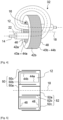
- FIG 3 represents a second embodiment of an inductive filtering device 40 according to the invention.
- the device 40 comprises a screen 42 arranged between the magnetic core 12 and the cable 14. Unlike the devices 10 and 30, the screen 42 is not arranged around the electric cable 14 in a coaxial manner.
- the screen 42 is arranged on at least one face of the magnetic core 12.
- An electrical insulator 43 is interposed between the screen 42 and the magnetic core 12.
- the electrical insulator 43 fulfills the function of the electrical insulator 24 present in the first embodiment.
- the screen 42 and the insulator 43 can be made by means of a metallized plastic film.
- the screen 42 comprises two parts 42a and 42b.
- the part 42a is arranged on an inner face 44a of the magnetic core 12 and the part 42b is arranged on an outer face 44b of the magnetic core 12.
- the insulator 43 comprises two parts 43a and 43b.
- the portion 43a is arranged on the inner face 44a of the magnetic core 12 and the portion 43b is arranged on the outer face 44b of the magnetic core 12. More precisely, the faces 44a and 44b are concentric with the central recess 16.
- the faces 44a and 44b have cylindrical sections around the axis 18.
- the face 44a forms an inner wall of the tubular shape of the magnetic core 12 and the face 44b forms an outer wall of the tubular shape of the magnetic core 12.
- the part 42a arranged on the internal face 42a is sufficient and it is not necessary to produce a part 42b on the external face 44b to arrange the screen between the cable 14 and the magnetic core 12.
- the part 42b is advantageous for completing the arrangement of the screen 42 between the cable 14 and the magnetic core 12.
- the magnetic core 12 comprises two faces 46 and 48 perpendicular to the axis 18. It is possible to complete the screen 42 and the insulator 43 by covering one of the faces 46 and 48 or even both. By covering one of the faces 46 or 48, the screen 42 can ensure electrical continuity between the parts 42a and 42b. In the event of covering the two faces 46 and 48 by the screen 42, it is important to break the electrical continuity of the screen 42 so as to avoid any possibility of current rotating in the screen 42 parallel to the turn(s) made by the cable 14 passing through the central recess 16.
- the screen 42 can be produced in the form of a metal braid arranged on the relevant faces of the magnetic core 12.
- Fixing the potential of the screen 42 is not useful. It is therefore possible to keep the screen 42, whether it is made in a single part or in several parts 42a and 42b to keep the screen 42 or even its different parts completely electrically isolated from their environment.
- the screen is formed of two shells 50 and 52 fitting into each other.
- the shell 50 comprises a flat face 50a in contact with the face 46 of the magnetic core 12.
- the shell 50 also comprises two cylindrical faces 50b and 50c extending along the axis 18 of the magnetic core 12.
- the cylindrical face 50b is in contact with the internal face 44a of the magnetic core 12 and the cylindrical face 50c is in contact with the external face 44b of the magnetic core 12.
- the shell 52 comprises a flat face 52a in contact with the face 48 of the magnetic core 12.
- the shell 52 also comprises two cylindrical faces 52b and 52c extending along the axis 18 of the magnetic core 12.
- the cylindrical face 52b is in contact with the cylindrical face 50b of the shell 50 and the cylindrical face 52c is in contact with the cylindrical face 50c of the shell 50.
- the shells are for example made of machined or cast metal.
- For each shell 50 and 52 its flat face and its cylindrical faces are electrically continuous.
- the shells 50 and 52 are covered with an electrical insulator at least between their faces in contact with the magnetic core 12 itself.
- the electrical insulator also provides insulation between the two shells 50 and 52 in order to prevent the formation of a turn around the magnetic core 12 as mentioned above.
- the electrical insulator may be formed of a plastic film completely or partially covering each of the shells 50 and 52.
- the two half-shells are completely electrically isolated from their environment.
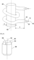
- the magnetic core 60 has an elongated shape surrounded by the cable 14. In the example shown, the magnetic core 60 does not have a recess passing through it. Alternatively, it is possible to implement a magnetic core having one or more recesses, and to wind the cable 14 around this magnetic core without passing through the recess(es).
- the magnetic core 60 has a cylindrical shape with a solid and circular section extending along an axis 62. Any other cylindrical shape of magnetic core is possible, for example having a section perpendicular to the axis 62 of square or rectangular shape.
- the magnetic core 60 can be pierced right through along the axis 62.
- the screen 20 reduces the appearance of high-frequency currents in the magnetic core 60 induced by high-frequency components present in the signal carried by the cable 14.
- the screen 20 is arranged around the cable 14 coaxially along the entire portion of the cable 14 wound around the magnetic core 60.
- the screen 20 is advantageous for the screen 20 to be extended beyond the winding of the cable 14 around the magnetic core 60.
- the projection of the screen beyond the winding is advantageously at least equal to the diameter ⁇ of the magnetic core 60.
- the minimum projection is shown in FIG. figure 5 .
- the magnetic core 60 it is possible to realize a screen as described in the figure 3 , that is, arranged on at least one of the faces of the magnetic core 60.
- the figure 6 describes a screen 66 surrounding the cylindrical face 64 of the magnetic core 60.
- the cable 14 is not shown. It is wound as in the figure 5 .
- the latter is interrupted substantially along a generatrix of the cylindrical shape of the magnetic core 60.
- the interruption can be made in another shape, for example in a helix around the axis 62 of the magnetic core 60 or even following a broken line. It is advantageous for the screen 66 to overlap beyond one turn at its interruption. Such an overlap 68 is visible on the figure 6 .
- the screen 66 can be made by means of a conductive film covered on its two faces with an electrical insulator.
- the insulator ensures the insulation of the screen 66 with respect to the magnetic core and on the other face with respect to the screen itself at the level of the covering and possibly with respect to the cable 14.
- the cable 14 is shown with a single electrical conductor passing through the magnetic core 12. It is entirely possible to implement the invention with a cable 14 comprising several electrical conductors insulated from each other. The conductors are then intended to carry different electrical voltages, for example the positive voltage and the negative voltage of the output of a direct current power supply or the phase and the neutral of a single-phase alternating current power supply. It is also possible to provide more than two electrical conductors grouped in the same cable, for example to filter the different output phases of a polyphase AC power supply.
Landscapes
- Engineering & Computer Science (AREA)
- Power Engineering (AREA)
- Microelectronics & Electronic Packaging (AREA)
- Coils Or Transformers For Communication (AREA)
- Filters And Equalizers (AREA)
Description
- L'invention concerne un dispositif de filtrage inductif. Ce type de filtrage est communément utilisé afin de réduire d'éventuelles perturbations présentes sur un signal véhiculé sur un câble électrique. Le dispositif est alors placé en série sur le câble. L'invention trouve une utilité particulière dans le domaine aéronautique où la tendance actuelle est d'augmenter le nombre d'équipements électriques et donc le nombre dispositifs de filtrage associés aux équipements. Dans ce domaine, la réduction de masse embarquée est un problème récurrent qui se pose. L'invention propose de réduire la masse des dispositifs de filtrage.
- De façon classique un dispositif de filtrage peut être formé par une inductance raccordée en série sur un conducteur électrique. La valeur de l'impédance d'une inductance est proportionnelle à la fréquence du courant qui la traverse. Une inductance est donc bien adaptée à filtrer les composantes à haute fréquence du courant circulant dans le conducteur électrique.
- L'inductance peut être réalisée au moyen d'un conducteur électrique enroulé autour d'un noyau magnétique permettant de canaliser le flux magnétique induit par le courant circulant dans le conducteur électrique. Afin d'optimiser la circulation du flux magnétique, il est possible de mettre en oeuvre un noyau magnétique fermé sans entrefer. Ce type de noyau est appelé par de nombreux fabricant : « noyau torique ». Il est formé autour d'un évidement central. La qualification de torique pour le noyau magnétique va bien au-delà de la définition mathématique d'un tore. On trouve notamment des noyaux magnétiques dits toriques à section circulaire, rectangulaire... L'inductance est réalisée en enroulant un conducteur électrique autour du noyau magnétique en traversant l'évidement central afin de former une ou plusieurs spires.
- La demanderesse a constaté que lors du filtrage d'harmoniques d'un courant dont la composante fondamentale est à basse fréquence, les harmoniques et plus généralement les composantes à haute fréquence, se superposant à la composante fondamentale du courant, génèrent des courants électriques induits importants dans le noyau magnétique. En effet, bien que les matériaux des noyaux magnétiques soient choisis pour leurs propriétés magnétiques, notamment pour leur perméabilité, ils sont également conducteurs de l'électricité. Cette propriété électrique permet la génération de courants induits. Plus la fréquence du courant circulant dans le conducteur est élevée, plus le courant induit est élevé.
- Ces courants importants circulent exclusivement dans le noyau magnétique sans en sortir et génère un échauffement par effet Joule. Or, plus la température d'un noyau augmente, plus la perméabilité magnétique du matériau du noyau diminue ce qui entraine une baisse de la valeur de l'inductance et en conséquence une augmentation du courant circulant dans le conducteur, notamment pour ses composantes à haute fréquence. Cette augmentation du courant génère un courant induit plus fort et donc un échauffement plus important. La demanderesse a même observé dans certains cas un emballement thermique pouvant entraîner la destruction du noyau magnétique.
- Pour limiter l'échauffement des circuits magnétiques, il serait possible de mettre en oeuvre des noyaux magnétiques réalisés à partir de matériaux possédant une plus forte résistivité électrique. Cependant leurs caractéristiques magnétiques sont bien moins bonnes que celles des noyaux magnétiques classiques.
- L'évacuation de la chaleur produite dans le noyau magnétique peut se faire en augmentant le volume du noyau magnétique afin d'augmenter sa surface de contact avec l'air ambiant. Il est également possible de prévoir dissipateur thermique fixé au noyau. Quelle que soit la solution retenue pour évacuer la chaleur, cala entraine une augmentation de masse et de volume de l'inductance.
- Un premier but de l'invention est de réduire la masse et le volume d'une inductance mettant en oeuvre un noyau magnétique. Ce but est atteint en limitant l'apparition de courant à haute fréquence dans le noyau magnétique autour duquel est entouré le conducteur de l'inductance.
- Pour limiter l'apparition de courant à haute fréquence dans le noyau magnétique, un écran conducteur est disposé entre le conducteur de l'inductance et le noyau magnétique. Cet écran a pour fonction de déplacer la génération de courants induits bouclés du noyau magnétique vers l'écran. Les courants induits sont opposés à ceux circulant dans le conducteur. Ainsi le noyau magnétique est soumis à deux courants opposés, ce qui tend à réduire le flux magnétique et donc les courants induits pouvant circuler dans le noyau magnétique. Autrement dit, la présence de l'écran permet de réduire très nettement l'apparition de courants induits dans le noyau magnétique et donc son échauffement.
- Le document
US 2016/365192 A1 divulgue un filtre anti-bruit comprenant un noyau magnétique en forme d'anneau, un enroulement autour du noyau magnétique et une borne de mise à la terre disposée entre le noyau magnétique et l'enroulement, la borne de mise à la terre étant connectée à une masse. La borne de mise à la terre comprend une partie conductrice qui entoure au moins une partie de la périphérie extérieure du noyau magnétique. - Le document
US 2001/050605 A1 divulgue un dispositif de filtrage du bruit comprenant un câble coaxial enroulé autour d'un noyau de ferrite en forme de tige. - Plus précisément, l'invention a pour objet un dispositif de filtrage inductif comprenant :
- un noyau magnétique dont le matériau possède des propriétés de conductions électriques,
- au moins un câble électrique enroulé autour du noyau magnétique en formant au moins une spire, le câble électrique étant destiné à véhiculer un signal électrique possédant au moins une composante alternative indésirable se superposant à une fréquence fondamentale du signal électrique et
- un écran électriquement conducteur, isolé électriquement de son environnement, l'écran étant disposé entre le noyau magnétique et le câble électrique de façon à permettre la génération dans l'écran, par induction électromagnétique, d'un courant dont la fréquence est supérieure à la fréquence fondamentale,
- Lorsque le dispositif est destiné à filtrer une fréquence donnée, l'écran possède avantageusement une épaisseur au moins égale à δ = (ρ/π.f.µ)1/2 avec ρ : la résistivité, et µ : la perméabilité magnétique absolue du matériau choisi pour réaliser l'écran.
- Dans un premier mode de réalisation d'un dispositif de filtrage inductif selon l'invention, le câble électrique s'étend selon un axe et l'écran est disposé autour du câble électrique de façon coaxiale.
- Dans ce premier mode, le noyau magnétique peut être de forme cylindrique en s'étendant autour d'un axe, l'écran dépasse avantageusement du noyau magnétique au-delà de la ou des spires formées autour du noyau magnétique. Le dépassement est avantageusement au moins égal à une plus grande dimension extérieure selon l'axe du noyau magnétique.
- Le câble peut être enroulé plusieurs fois autour du noyau magnétique en formant plusieurs spires autour du noyau magnétique.
- Dans un second mode de réalisation d'un dispositif de filtrage inductif selon l'invention, l'écran est disposé sur au moins une face du noyau magnétique.
- Dans le second mode, l'écran peut comprendre plusieurs parties, chaque partie étant disposée de façon à recouvrir une des faces du noyau magnétique.
- Dans le second mode, l'écran peut comprendre deux coquilles s'emboitant l'une dans l'autre, les deux coquilles étant isolées électriquement l'une de l'autre.
- Le noyau magnétique peut posséder un évidement central et le câble électrique peut être enroulé autour du noyau magnétique en traversant l'évidement central.
- L'invention sera mieux comprise et d'autres avantages apparaîtront à la lecture de la description détaillée de plusieurs modes de réalisation donnés à titre d'exemple, description illustrée par le dessin joint dans lequel :
- [
Fig. 1 ] lafigure 1 représente une première variante d'enroulement d'un câble d'un premier mode de réalisation de l'invention ; - [
Fig. 2 ] lafigure 2 représente une seconde variante d'enroulement du câble du premier mode de réalisation de l'invention ; - [
Fig. 3 ] lafigure 3 représente un second mode de réalisation de l'invention ; - [
Fig. 4 ] lafigure 4 représente un noyau magnétique et un écran mis en oeuvre dans une variante du second mode de réalisation de l'invention ; - [
Fig. 5 ] lafigure 5 représente le premier mode de réalisation adapté à une variante de noyau magnétique ; - [
Fig. 6 ] lafigure 6 représente le second mode de réalisation adapté à la variante de noyau magnétique de lafigure 5 . - Par souci de clarté, les mêmes éléments porteront les mêmes repères dans les différentes figures.
- La
figure 1 représente un dispositif 10 de filtrage inductif comprenant un noyau magnétique 12 et un câble électrique 14. Autrement dit, le dispositif 10 de filtrage inductif forme une inductance. Le noyau magnétique 12 est formé autour d'un évidement central 16. Le noyau magnétique 12 est de forme tubulaire s'étendant autour d'un axe 18. L'évidement central 16 se développe autour de l'axe 18. Le noyau magnétique 12 est fermé et par exemple sans entrefer. Sur lafigure 1 , le noyau magnétique 12 possède une section circulaire perpendiculairement à l'axe 18. D'autres sections sont possibles dans le cadre de l'invention, par exemple une section rectangulaire, triangulaire... La section circulaire est bien adaptée au passage d'un câble électrique 14 également à section circulaire ne traversant qu'une seule fois l'évidement central. Le câble 14 s'étend selon un axe 19. Dans le cas d'un seul passage, les axes, 18 du noyau magnétique 12 et 19 du câble 14, sont sensiblement confondus au jeu fonctionnel près entre le câble 14 et l'évidement central 16. Comme on le verra plus loin, le câble électrique 14 peut traverser plusieurs fois l'évidement central 16. Il peut alors être avantageux de ranger les différents passages dans l'évidement central 16 pour occuper une section différente d'une section circulaire. La forme du noyau magnétique 12 peut également être guidée par l'environnement du dispositif 10. Il peut être plus facile de ranger un dispositif 10 dont le noyau magnétique 12 est à section rectangulaire. - Ce type de noyau magnétique fermé sans entrefer est habituellement appelé « torique » chez de nombreux fabricants. Ce qualificatif va bien au-delà de la forme d'un tore telle que définie mathématiquement. On trouve notamment des noyaux magnétiques dits toriques à section circulaire, rectangulaire... L'absence d'entrefer permet de conserver le champ magnétique se développant dans le noyau magnétique 12 uniquement dans le matériau du noyau magnétique sans être perturbé par un entrefer.
- Selon l'invention, le dispositif 10 comprend un écran 20 électriquement conducteur, disposé entre le noyau magnétique 12 et le câble électrique 14. L'écran 20 est isolé électriquement du câble électrique 14 et du noyau magnétique 12. Dans le mode de réalisation représenté sur la
figure 1 , l'écran 20 est disposé autour du câble électrique 14. L'écran 20 est coaxial avec le câble 14. Un isolant électrique 22 est disposé entre le câble 14 et l'écran 20. L'isolant électrique 22 peut être une gaine extérieure du câble 14. Un autre isolant électrique 24 est disposé entre l'écran 20 et le noyau magnétique 12. Dans le mode de réalisation représenté sur lafigure 1 , l'isolant 24 recouvre l'écran 20. Alternativement, l'isolant 24 peut recouvrir le noyau magnétique 12 et notamment la face interne de l'évidement central 16. - La disposition de l'écran 20 entre le câble 14 et le noyau magnétique 12 permet la circulation de courants dans l'écran 20. Ces courants sont générés par induction électromagnétique formée par le courant circulant dans le câble 14.
- Le dispositif 10 permet un filtrage inductif d'un courant circulant dans le câble 14. Ce courant peut être bruité. Plus précisément, le courant circulant dans le câble 14 comprend une fréquence fondamentale et des fréquences plus élevées dont on cherche à réduire l'amplitude au moyen du dispositif 10. Dans le cas d'un courant continu circulant dans le câble 14, la fréquence fondamentale est nulle. Les fréquences plus élevées sont formées de toutes composantes alternatives se superposant à la composante continue du courant ou à la composante fondamentale alternative dans le cas d'un courant alternatif circulant dans le câble 14. Ces composantes alternatives de fréquence supérieures à la fréquence fondamentale peuvent être dues à la production du courant continu au moyen d'un redresseur. En effet, on retrouve, se superposant au courant continu, des traces de fréquences présentes en amont du redresseur. Les composantes alternatives indésirables peuvent également être dues à des réjections de courant émises par des charges alimentées par le câble 14 ou à des perturbations électromagnétiques que peut subir le câble 14. Dans l'écran 20, on s'intéresse principalement à la génération de courants induits par les composantes alternatives indésirables du courant circulant dans le câble 14.
- Il est possible d'adapter l'épaisseur de l'écran 20 aux fréquences que l'on souhaite filtrer. Ces fréquences peuvent être bien au-delà de la fréquence fondamentale. De façon générale, dans un conducteur massif, les courants à haute fréquence circulent essentiellement dans la peau du conducteur. De ce fait, pour filtrer de façon efficace une fréquence donnée et les fréquences supérieures, l'épaisseur δ de l'écran 20 doit avoir au moins l'épaisseur de la peau dans laquelle circule le courant à la fréquence donnée. En deçà de cette épaisseur, le filtrage de la fréquence donnée demeure, mais avec moins d'efficacité. Il est possible de prendre une marge de sécurité dans la détermination de l'épaisseur δ de l'écran 20 en choisissant une épaisseur au moins égale à deux ou trois fois l'épaisseur de la peau dans laquelle circule le courant à la fréquence donnée. L'épaisseur de peau est donnée par la formule suivante :

avec ρ : la résistivité, et µ la perméabilité magnétique absolue du matériau choisi pour réaliser l'écran 20. - Selon l'axe 19 du câble 14, l'écran 20 possède une longueur finie L selon l'axe 19 du câble 14, avantageusement supérieure à la longueur l du noyau magnétique 12 selon son axe 18. Le fait que la longueur L de l'écran 20 soit finie permet d'éviter la circulation dans l'écran 20 de courant dans une direction parallèle à l'axe 19 du câble 14. De tels courants ne sont pas souhaitables car ils s'opposeraient au passage de la fréquence fondamentale dans le câble 14 en formant un transformateur. En pratique, le passage du câble 14 au travers de l'évidement central 16 est assimilé à une spire entourant le noyau magnétique 2. Plus précisément, lorsqu'un courant circule dans le câble 14, celui-ci forme un circuit fermé avec au moins un générateur et une charge. Ce circuit fermé forme une spire autour d'une section du noyau magnétique 12, section formée dans un plan contenant l'axe 18. Par ailleurs, la circulation d'un courant dans l'écran 20 parallèlement à l'axe 19 du câble 14 formerait de la même façon une autre spire autour d'une section du noyau magnétique 12. La spire du câble 12 et celle de l'écran formerait alors le transformateur évoqué plus haut, transformateur qu'il est souhaitable d'éviter.
- Il est possible de fixer le potentiel de l'écran 20 en le raccordant électriquement par exemple à une masse électrique de l'équipement dans lequel est installé le dispositif 10. Ce raccordement doit se faire en un seul point de l'écran 20 afin d'éviter la création par l'écran 20 d'une spire autour du noyau magnétique. Alternativement, pour simplifier la réalisation du dispositif 10, l'écran 20 peut être isolé électriquement de son environnement, c'est-à-dire que l'écran 20 ne possède aucun raccordement électrique. Le potentiel de l'écran 20 est laissé flottant. Des essais en interne ont montré que cette isolation électrique complète permettait à l'écran de remplir sa fonction principale de limitation de l'échauffement du noyau magnétique 12. Autrement dit, lorsque le dispositif est en fonctionnement, l'écran 20 n'est raccordé électriquement ni au noyau magnétique 12, ni au câble 14, ni à aucune source de potentiel de l'équipement auquel le dispositif appartient.
- L'écran 20 entourant le câble 14, des courants tournant autour de l'axe du câble peuvent s'y développer. De tels courants sont notamment induits par les composantes alternatives indésirables du courant circulant dans le câble 14.
- Le matériau formant le noyau magnétique 12 ayant des propriétés de conductions électriques, en l'absence d'écran 20, les composantes alternatives indésirables induisent, dans le noyau magnétique 12, des courants tournant autour de l'évidement central 16. La présence de l'écran 20 dans lequel se développent des courants tournants induits par les composantes alternatives indésirables circulant dans le câble 14 permet d'atténuer les courants tournants dans le noyau magnétique 12. En effet, le noyau magnétique est soumis par induction à des courants tournants dans le câble 14 et à des courants opposés tournant dans l'écran 20. Cette opposition des courants tournant dans le câble 14 et dans l'écran 20 permet de limiter la génération de courants induits dans le noyau magnétique 12, ce qui permet de limiter son échauffement par effet Joule.
- La
figure 2 représente une variante du mode de réalisation du dispositif 10 représenté sur lafigure 1 . Lafigure 2 représente un dispositif 30 de filtrage inductif, formant également une inductance et dans lequel on retrouve le noyau magnétique 12, le câble 14 et l'écran 20. A la différence du dispositif 10, le câble 14 du dispositif 30 traverse deux fois l'évidement central 16 en formant une seconde spire 32 autour du noyau magnétique 12. Dans le cadre de l'invention, il est bien entendu possible de réaliser autant de spires 32 que nécessaire pour assurer le filtrage souhaité. L'axe 19 du câble 14 suit la forme de la spire 32 et l'écran 20 reste ici coaxial du câble 14. Autrement dit, l'écran 20 suit l'axe 19 du câble 14. Les axes 18 et 19 ne sont pas confondus. Comme dans la variante de lafigure 1 , l'écran 20 du dispositif 30 ne forme pas de spire autour du noyau magnétique 12. L'isolant électrique 24 présente ici un intérêt pour éviter des courts-circuits entre les spires formées par l'écran 20 autour du noyau magnétique. En effet, de tels courts-circuits entraineraient des courants tournants parallèlement au courant circulant dans le câble 14. - L'écran 20 possède une longueur L définie le long de l'axe 19 du câble 14. L'écran 20 dépasse du noyau magnétique 12 de part et d'autre du passage du câble 14 au travers de l'évidement central 16. Des essais en interne ont montré que pour obtenir une efficacité optimale du filtrage, il est avantageux que l'écran 20 dépasse de chaque côté noyau magnétique 12 selon l'axe 18. Un dépassement optimal est au moins égal à une dimension extérieure caractéristique du noyau magnétique 12 perpendiculairement à son axe 18. Par exemple pour un noyau magnétique 12 cylindrique, le dépassement est au moins égal au diamètre extérieur Φ du noyau magnétique 12, comme représenté sur la
figure 1 . Avec un tel dépassement, il n'y a quasiment plus d'induction entre le câble 14 et le noyau magnétique 12. Avec un noyau magnétique de forme tubulaire et à section carrée ou rectangulaire, la dimension caractéristique est par exemple la diagonale de la section carrée ou rectangulaire. Plus généralement, un dépassement optimal est au moins égal à une plus grande dimension extérieure caractéristique du noyau magnétique. - Comme précédemment, dans la variante de la
figure 2 , le potentiel de l'écran 20 peut être fixé en le raccordant électriquement par exemple à une masse électrique de l'équipement dans lequel est installé le dispositif 30. Ce raccordement se fait en un seul point de l'écran 20 afin d'éviter la création par l'écran 20 d'une spire autour du noyau magnétique 12. - L'écran 20 peut être réalisé au moyen d'un feuillard ou d'une tresse métallique par exemple en alliage de cuivre ou d'aluminium entourant le câble 14. Tout autre matériau conducteur de l'électricité peut bien entendu être mis en oeuvre. Il est possible de mettre en oeuvre un film plastique métallisé. Le film plastique proprement dit remplit la fonction de l'isolant 24 et la métallisation celle de l'écran 20.
- La
figure 3 représente un second mode de réalisation d'un dispositif 40 de filtrage inductif conforme à l'invention. Dans ce mode de réalisation on retrouve le noyau magnétique 12 ainsi que le câble 14 et son isolant 22. Sur lafigure 3 , le câble 14 forme une spire 32 autour du noyau magnétique 12. Le second mode de réalisation peut être mis en oeuvre avec autant de spires 32 que nécessaire ou même sans spire 32 comme dans la variante de lafigure 1 . Le dispositif 40 comporte un écran 42 disposé entre le noyau magnétique 12 et le câble 14. A la différence des dispositifs 10 et 30, l'écran 42 n'est pas disposé autour du câble électrique 14 de façon coaxiale. L'écran 42 est disposé sur au moins une face du noyau magnétique 12. Un isolant électrique 43 est interposé entre l'écran 42 et le noyau magnétique 12. L'isolant électrique 43 remplit la fonction de l'isolant électrique 24 présent dans le premier mode de réalisation. L'écran 42 et l'isolant 43 peuvent être réalisés au moyen d'un film plastique métallisé. - Dans le mode de réalisation de la
figure 3 , l'écran 42 comprend deux parties 42a et 42b. La partie 42a est disposée sur une face interne 44a du noyau magnétique 12 et la partie 42b est disposée sur une face externe 44b du noyau magnétique 12. De même, l'isolant 43 comprend deux parties 43a et 43b. La partie 43a est disposée sur la face interne 44a du noyau magnétique 12 et la partie 43b est disposée sur la face externe 44b du noyau magnétique 12. Plus précisément, les faces 44a et 44b sont concentriques de l'évidement central 16. Les faces 44a et 44b possèdent des sections cylindriques autour de l'axe 18. La face 44a forme une paroi interne de la forme tubulaire du noyau magnétique 12 et la face 44b forme une paroi externe de la forme tubulaire du noyau magnétique 12. Lorsque le câble 14 ne traverse qu'une seule fois l'évidement central 16, comme dans la variante de lafigure 1 , la partie 42a disposée sur la face interne 42a suffit et il n'est pas nécessaire de réaliser une partie 42b sur la face externe 44b pour disposer l'écran entre le câble 14 et le noyau magnétique 12. Par contre lorsque le câble 14 traverse plusieurs fois l'évidement central 16 pour former une ou plusieurs spires 32, la partie 42b est avantageuse pour compléter la disposition de l'écran 42 entre le câble 14 et le noyau magnétique 12. - Le noyau magnétique 12 comprend deux faces 46 et 48 perpendiculaires à l'axe 18. Il est possible de compléter l'écran 42 et l'isolant 43 en recouvrant l'une des faces 46 et 48 voire les deux. En recouvrant l'une des faces 46 ou 48 l'écran 42 peut assurer une continuité électrique entre les parties 42a et 42b. En cas de recouvrement des deux faces 46 et 48 par l'écran 42, il est important de rompre la continuité électrique de l'écran 42 de façon à éviter toute possibilité de courant tournant dans l'écran 42 parallèlement à la ou aux spires réalisées par le câble 14 traversant l'évidement central 16.
- L'écran 42 peut être réalisé sous forme d'une tresse métallique disposée sur les faces concernées du noyau magnétique 12.
- La fixation du potentiel de l'écran 42 n'est pas utile. Il est donc possible de conserver l'écran 42, qu'il soit réalisé en une seule partie ou en plusieurs parties 42a et 42b de conserver l'écran 42 ou même ses différentes parties complètement isolées électriquement de leur environnement.
- La
figure 4 représente une variante d'un écran adapté au second mode de réalisation. Pour ne pas surcharger lafigure 4 , seul le noyau magnétique 12 et l'écran sont représentés. L'écran est formé de deux coquilles 50 et 52 s'emboitant l'une dans l'autre. La coquille 50 comprend une face plane 50a en contact avec la face 46 du noyau magnétique 12. La coquille 50 comprend aussi deux faces cylindriques 50b et 50c s'étendant selon l'axe 18 du noyau magnétique 12. La face cylindrique 50b est en contact avec la face interne 44a du noyau magnétique 12 et la face cylindrique 50c est en contact avec la face externe 44b du noyau magnétique 12. De même, la coquille 52 comprend une face plane 52a en contact avec la face 48 du noyau magnétique 12. La coquille 52 comprend aussi deux faces cylindriques 52b et 52c s'étendant selon l'axe 18 du noyau magnétique 12. La face cylindrique 52b est en contact avec la face cylindrique 50b de la coquille 50 et la face cylindrique 52c est en contact avec la face cylindrique 50c de la coquille 50. Les coquilles sont par exemple réalisées en métal usiné ou moulé. Pour chaque coquille 50 et 52, sa face plane et ses faces cylindriques sont continues électriquement. Les coquilles 50 et 52 sont recouvertes d'un isolant électrique au moins entre leurs faces en contact avec le noyau magnétique 12 lui-même. L'isolant électrique assure aussi une isolation entre les deux coquilles 50 et 52 afin d'éviter la formation d'une spire autour du noyau magnétique 12 comme évoqué plus haut. L'isolant électrique peut être formé d'un film plastique recouvrant complètement ou partiellement chacune des coquilles 50 et 52. - Comme précédemment, les deux demi-coquilles sont complètement isolées électriquement de leur environnement.
- Les
figures 5 et 6 représentent l'invention adaptée à une autre forme de noyau magnétique. Plus précisément, sur lesfigures 5 et 6 , le noyau magnétique 60 possède une forme longiligne entourée pas le câble 14. Dans l'exemple représenté, le noyau magnétique 60 ne possède pas d'évidement le traversant. Alternativement, il est possible de mettre en oeuvre un noyau magnétique possédant un ou plusieurs évidements, et d'enrouler le câble 14 autour de ce noyau magnétique sans traverser le ou les évidements. Le noyau magnétique 60 possède une forme cylindrique à section pleine et circulaire s'étendant selon un axe 62. Toute autre forme cylindrique de noyau magnétique est possible, par exemple possédant une section perpendiculaire à l'axe 62 de forme carrée ou rectangulaire. Le noyau magnétique 60 peut être percé de part en part selon l'axe 62. - Sur la
figure 5 , on retrouve le câble 14 desfigures 1 et 2 entouré du premier isolant 22, de l'écran 20 et du second isolant 24. Le câble 14 est enroulé autour du noyau magnétique 60. L'axe 62 forme l'axe d'enroulement du câble 14. Sur lafigure 5 , le câble 14 est enroulé sur deux tours. Il est bien entendu possible de mettre en oeuvre l'invention quel que soit le nombre de tours du câble 14 autour du noyau magnétique 60. Dans cette configuration, l'écran 20 réduit l'apparition de courants haute fréquence dans le noyau magnétique 60 induits par des composantes haute fréquence présentes dans le signal véhiculé par le câble 14. Dans l'exemple représenté sur lafigure 5 , l'écran 20 est disposé autour du câble 14 de façon coaxiale tout au long de la partie du câble 14 enroulée autour du noyau magnétique 60. Comme précédemment, il est avantageux que l'écran 20 soit prolongé au-delà de l'enroulement du câble 14 autour du noyau magnétique 60. Dans ce mode de réalisation le dépassement de l'écran au-delà de l'enroulement est avantageusement au moins égal au diamètre Φ du noyau magnétique 60. Le dépassement minimum est représenté sur lafigure 5 . - Avec le noyau magnétique 60, il est possible de réaliser un écran comme décrit sur la
figure 3 , c'est-à-dire, disposé sur au moins une des faces du noyau magnétique 60. Lafigure 6 décrit un écran 66 entourant la face cylindrique 64 du noyau magnétique 60. Pour ne pas surcharger la figure, le câble 14 n'est pas représenté. Il est enroulé comme sur lafigure 5 . Pour éviter de générer des courants induits dans l'écran 66, celui-ci est interrompu sensiblement le long d'une génératrice de la forme cylindrique du noyau magnétique 60. L'interruption peut être réalisée selon une autre forme, par exemple en hélice autour de l'axe 62 du noyau magnétique 60 ou même en suivant une ligne brisée. Il est avantageux que l'écran 66 se recouvre au-delà d'un tour au niveau de son interruption. Un tel recouvrement 68 est visible sur lafigure 6 . Pour assurer un recouvrement sans contact électrique entre les extrémités de l'écran au niveau de son interruption, l'écran 66 peut être réalisé au moyen d'un film conducteur recouvert sur ses deux faces d'un isolant électrique. Sur une des faces, l'isolant assure l'isolation de l'écran 66 vis-à-vis du noyau magnétique et sur l'autre face vis-à-vis de l'écran lui-même au niveau du recouvrement et éventuellement vis-à-vis du câble 14. Ici encore, il est inutile de raccorder électriquement l'écran 66 et l'isolant électrique le recouvrant peut être réalisé sous forme d'un film continu. - Dans les différents modes de réalisation, le câble 14 est représenté avec un seul conducteur électrique traversant le noyau magnétique 12. Il est tout à fait possible de mettre en oeuvre l'invention avec un câble 14 comprenant plusieurs conducteurs électriques isolés entre eux. Les conducteurs sont alors destinés à porter des tensions électriques différentes, par exemple la tension positive et la tension négative de la sortie d'une alimentation en courant continue ou la phase et le neutre d'une alimentation alternative monophasée. Il est également possible de prévoir plus de deux conducteurs électriques regroupés dans un même câble, par exemple pour filtrer les différentes phases de sortie d'une alimentation alternative polyphasée.
Claims (9)
- Dispositif de filtrage inductif comprenant :- un noyau magnétique (12 ; 60) dont le matériau possède des propriétés de conductions électriques,- au moins un câble électrique (14) enroulé autour du noyau magnétique (12 ; 60) en formant au moins une spire (32), le câble électrique (14) étant destiné à véhiculer un signal électrique possédant au moins une composante alternative indésirable se superposant à une fréquence fondamentale du signal électrique et- un écran (20 ; 42 ; 50, 52 ; 66) électriquement conducteur, isolé électriquement de son environnement,l'écran (20 ; 42 ; 50, 52 ; 66) étant disposé entre le noyau magnétique (12 ; 60) et le câble électrique (14) de façon à permettre la génération dans l'écran (20 ; 42 ; 50, 52 ; 66), par induction électromagnétique, d'un courant dont la fréquence est supérieure à la fréquence fondamentale,l'écran (20 ; 42 ; 50, 52 ; 66) étant configuré de façon à ne pas permettre la circulation d'un courant dans l'écran (20 ; 42 ; 50, 52 ; 66) dans une direction parallèle à celle de la ou des spires (32) formées par l'enroulement du câble électrique (14) autour du noyau magnétique.
- Dispositif de filtrage inductif selon la revendication 1, le dispositif étant destiné à filtrer une fréquence f donnée, dans lequel l'écran (20 ; 42 ; 50, 52 ; 66) a une épaisseur au moins égale à δ = (ρ/π.f.µ)1/2 avec ρ : la résistivité, et µ : la perméabilité magnétique absolue du matériau choisi pour réaliser l'écran (20 ; 42 ; 50, 52 ; 66).
- Dispositif de filtrage inductif selon la revendication 1, dans lequel le câble électrique (14) s'étend selon un axe (19) et dans lequel l'écran (20) est disposé autour du câble électrique (14) de façon coaxiale.
- Dispositif de filtrage inductif selon la revendication 3, dans lequel le noyau magnétique (12) est de forme cylindrique s'étendant autour d'un axe (18), dans lequel l'écran (20) dépasse du noyau magnétique (12) au-delà de la ou des spires formées autour du noyau magnétique (12 ; 60), le dépassement étant au moins égal à une plus grande dimension extérieure selon l'axe (18) du noyau magnétique (12).
- Dispositif de filtrage inductif selon l'une des revendications précédentes, dans lequel le câble (14) est enroulé plusieurs fois autour du noyau magnétique (12 ; 60) en formant plusieurs spires (32) autour du noyau magnétique (12 ; 60).
- Dispositif de filtrage inductif selon l'une des revendications précédentes, dans lequel l'écran (42 ; 66) est disposé sur au moins une face (44a, 44b, 46, 48 ; 64) du noyau magnétique (12 ; 60).
- Dispositif de filtrage inductif selon la revendication 6, dans lequel l'écran (42) comprend plusieurs parties (42a, 42b), chaque partie étant disposée de façon à recouvrir une des faces (44a, 44b, 46, 48) du noyau magnétique (12).
- Dispositif de filtrage inductif selon la revendication 6, dans lequel l'écran comprend deux coquilles (50, 52) s'emboitant l'une dans l'autre, les deux coquilles (50, 52) étant isolées électriquement l'une de l'autre.
- Dispositif de filtrage inductif selon l'une des revendications précédentes, dans lequel le noyau magnétique (12) possède un évidement central (16), et dans lequel le câble électrique (14) est enroulé autour du noyau magnétique (12) en traversant l'évidement central (16).
Applications Claiming Priority (1)
| Application Number | Priority Date | Filing Date | Title |
|---|---|---|---|
| FR2007872A FR3112913B1 (fr) | 2020-07-27 | 2020-07-27 | Dispositif de filtrage inductif à limitation d’échauffement |
Publications (2)
| Publication Number | Publication Date |
|---|---|
| EP3945533A1 EP3945533A1 (fr) | 2022-02-02 |
| EP3945533B1 true EP3945533B1 (fr) | 2024-10-16 |
Family
ID=74045525
Family Applications (1)
| Application Number | Title | Priority Date | Filing Date |
|---|---|---|---|
| EP21187083.7A Active EP3945533B1 (fr) | 2020-07-27 | 2021-07-22 | Dispositif de filtrage inductif a limitation d'echauffement |
Country Status (3)
| Country | Link |
|---|---|
| US (1) | US12476034B2 (fr) |
| EP (1) | EP3945533B1 (fr) |
| FR (1) | FR3112913B1 (fr) |
Families Citing this family (1)
| Publication number | Priority date | Publication date | Assignee | Title |
|---|---|---|---|---|
| CN114242412B (zh) * | 2021-11-04 | 2024-08-27 | 华为数字能源技术有限公司 | 磁元件和电子设备 |
Family Cites Families (4)
| Publication number | Priority date | Publication date | Assignee | Title |
|---|---|---|---|---|
| JP4579448B2 (ja) * | 2000-06-12 | 2010-11-10 | マスプロ電工株式会社 | 雑音除去装置 |
| JP2017005572A (ja) * | 2015-06-12 | 2017-01-05 | Necトーキン株式会社 | ノイズフィルタ、多段接続lcフィルタ及び医療用機器 |
| FR3076391B1 (fr) * | 2017-12-28 | 2025-02-21 | Thales Sa | Dispositif de filtrage inductif a noyau magnetique torique |
| FR3095725B1 (fr) * | 2019-05-02 | 2022-05-27 | Thales Sa | Dispositif de filtrage inductif et architecture électrique mettant en oeuvre le dispositif de filtrage |
-
2020
- 2020-07-27 FR FR2007872A patent/FR3112913B1/fr active Active
-
2021
- 2021-07-22 US US17/383,078 patent/US12476034B2/en active Active
- 2021-07-22 EP EP21187083.7A patent/EP3945533B1/fr active Active
Also Published As
| Publication number | Publication date |
|---|---|
| US20220028594A1 (en) | 2022-01-27 |
| FR3112913A1 (fr) | 2022-01-28 |
| EP3945533A1 (fr) | 2022-02-02 |
| US12476034B2 (en) | 2025-11-18 |
| FR3112913B1 (fr) | 2023-01-27 |
Similar Documents
| Publication | Publication Date | Title |
|---|---|---|
| EP0165835B1 (fr) | Capteur de courant à noyau amagnétique | |
| WO1999001773A1 (fr) | Capteur de courant | |
| EP0109867A1 (fr) | Dispositif capteur de champ magnétique alternatif à haute sensibilité, et à large bande, et appareil de mesure l'utilisant | |
| FR3076657A1 (fr) | Transformateur de courant ouvrant a noyau magnetique souple | |
| CA2881004C (fr) | Dispositif de puissance bobine comportant un enroulement d'un premier bobinage et un enroulement d'un deuxieme bobinage qui enveloppent une meme portion d'une jambe de noyau magnetique | |
| EP3945533A1 (fr) | Dispositif de filtrage inductif a limitation d'echauffement | |
| FR2899389A1 (fr) | Terminaison de connexion d'un cable supraconducteur | |
| EP0355145A1 (fr) | Dispositif d'injection d'un signal electromagnetique dans un conducteur electrique | |
| EP1920510A1 (fr) | Bougie d'allumage plasma pour un moteur a combustion interne | |
| WO1987005148A1 (fr) | Transformateur haute tension | |
| FR3009885A3 (fr) | ||
| FR2799840A1 (fr) | Capteur de courant differentiel | |
| FR3076391A1 (fr) | Dispositif de filtrage inductif a noyau magnetique torique | |
| WO2021116599A1 (fr) | Dispositif électrotechnique pour un aéronef comprenant des composants bobinés basse fréquence | |
| EP1732187B1 (fr) | Bougie à plasma radiofréquence pour l'allumage commandé de moteurs à combustion interne | |
| FR2545293A1 (fr) | Machine electromagnetique a induction lineaire | |
| FR2731295A1 (fr) | Bobine d'allumage a aimant de polarisation et a couplage optimise | |
| FR3104801A1 (fr) | Dispositif électrotechnique pour un aéronef | |
| EP0047966A1 (fr) | Dispositif de connexion entre une bague collectrice et une amenée de courant d'un rotor supraconducteur | |
| EP4732310A1 (fr) | Dispositif de filtrage inductif a masse reduite | |
| FR2972890A1 (fr) | Systeme inductif pouvant servir de creuset froid | |
| FR2701591A1 (fr) | Transformateur de courant non blindé à couplage par de l'air. | |
| EP0727794A1 (fr) | Transformateur, notamment pour convertisseur d'énergie, et convertisseur d'énergie à résonance doté d'une tel transformateur | |
| FR3116646A1 (fr) | Câble de puissance à filtre intégré | |
| EP1182760A1 (fr) | Cloison étanche de compartimentage et installation électrique blindée trphasée à isolation gazeuse pourvue d'une telle cloison |
Legal Events
| Date | Code | Title | Description |
|---|---|---|---|
| PUAI | Public reference made under article 153(3) epc to a published international application that has entered the european phase |
Free format text: ORIGINAL CODE: 0009012 |
|
| STAA | Information on the status of an ep patent application or granted ep patent |
Free format text: STATUS: THE APPLICATION HAS BEEN PUBLISHED |
|
| AK | Designated contracting states |
Kind code of ref document: A1 Designated state(s): AL AT BE BG CH CY CZ DE DK EE ES FI FR GB GR HR HU IE IS IT LI LT LU LV MC MK MT NL NO PL PT RO RS SE SI SK SM TR |
|
| STAA | Information on the status of an ep patent application or granted ep patent |
Free format text: STATUS: REQUEST FOR EXAMINATION WAS MADE |
|
| 17P | Request for examination filed |
Effective date: 20220729 |
|
| RBV | Designated contracting states (corrected) |
Designated state(s): AL AT BE BG CH CY CZ DE DK EE ES FI FR GB GR HR HU IE IS IT LI LT LU LV MC MK MT NL NO PL PT RO RS SE SI SK SM TR |
|
| GRAP | Despatch of communication of intention to grant a patent |
Free format text: ORIGINAL CODE: EPIDOSNIGR1 |
|
| STAA | Information on the status of an ep patent application or granted ep patent |
Free format text: STATUS: GRANT OF PATENT IS INTENDED |
|
| INTG | Intention to grant announced |
Effective date: 20240126 |
|
| RIN1 | Information on inventor provided before grant (corrected) |
Inventor name: GUGUEN, STEPHANE Inventor name: KHERBOUCHI, HOCINE Inventor name: DUBOIS, ERIC RAVINDRANATH |
|
| GRAJ | Information related to disapproval of communication of intention to grant by the applicant or resumption of examination proceedings by the epo deleted |
Free format text: ORIGINAL CODE: EPIDOSDIGR1 |
|
| STAA | Information on the status of an ep patent application or granted ep patent |
Free format text: STATUS: REQUEST FOR EXAMINATION WAS MADE |
|
| GRAP | Despatch of communication of intention to grant a patent |
Free format text: ORIGINAL CODE: EPIDOSNIGR1 |
|
| STAA | Information on the status of an ep patent application or granted ep patent |
Free format text: STATUS: GRANT OF PATENT IS INTENDED |
|
| INTC | Intention to grant announced (deleted) | ||
| INTG | Intention to grant announced |
Effective date: 20240516 |
|
| RAP1 | Party data changed (applicant data changed or rights of an application transferred) |
Owner name: SAFRAN ELECTRICAL & POWER |
|
| GRAS | Grant fee paid |
Free format text: ORIGINAL CODE: EPIDOSNIGR3 |
|
| GRAA | (expected) grant |
Free format text: ORIGINAL CODE: 0009210 |
|
| STAA | Information on the status of an ep patent application or granted ep patent |
Free format text: STATUS: THE PATENT HAS BEEN GRANTED |
|
| AK | Designated contracting states |
Kind code of ref document: B1 Designated state(s): AL AT BE BG CH CY CZ DE DK EE ES FI FR GB GR HR HU IE IS IT LI LT LU LV MC MK MT NL NO PL PT RO RS SE SI SK SM TR |
|
| REG | Reference to a national code |
Ref country code: GB Ref legal event code: FG4D Free format text: NOT ENGLISH |
|
| REG | Reference to a national code |
Ref country code: DE Ref legal event code: R096 Ref document number: 602021020252 Country of ref document: DE Ref country code: CH Ref legal event code: EP |
|
| REG | Reference to a national code |
Ref country code: IE Ref legal event code: FG4D Free format text: LANGUAGE OF EP DOCUMENT: FRENCH |
|
| REG | Reference to a national code |
Ref country code: LT Ref legal event code: MG9D |
|
| REG | Reference to a national code |
Ref country code: NL Ref legal event code: MP Effective date: 20241016 |
|
| REG | Reference to a national code |
Ref country code: AT Ref legal event code: MK05 Ref document number: 1733645 Country of ref document: AT Kind code of ref document: T Effective date: 20241016 |
|
| PG25 | Lapsed in a contracting state [announced via postgrant information from national office to epo] |
Ref country code: NL Free format text: LAPSE BECAUSE OF FAILURE TO SUBMIT A TRANSLATION OF THE DESCRIPTION OR TO PAY THE FEE WITHIN THE PRESCRIBED TIME-LIMIT Effective date: 20241016 |
|
| PG25 | Lapsed in a contracting state [announced via postgrant information from national office to epo] |
Ref country code: NL Free format text: LAPSE BECAUSE OF FAILURE TO SUBMIT A TRANSLATION OF THE DESCRIPTION OR TO PAY THE FEE WITHIN THE PRESCRIBED TIME-LIMIT Effective date: 20241016 |
|
| PG25 | Lapsed in a contracting state [announced via postgrant information from national office to epo] |
Ref country code: IS Free format text: LAPSE BECAUSE OF FAILURE TO SUBMIT A TRANSLATION OF THE DESCRIPTION OR TO PAY THE FEE WITHIN THE PRESCRIBED TIME-LIMIT Effective date: 20250216 Ref country code: PT Free format text: LAPSE BECAUSE OF FAILURE TO SUBMIT A TRANSLATION OF THE DESCRIPTION OR TO PAY THE FEE WITHIN THE PRESCRIBED TIME-LIMIT Effective date: 20250217 Ref country code: HR Free format text: LAPSE BECAUSE OF FAILURE TO SUBMIT A TRANSLATION OF THE DESCRIPTION OR TO PAY THE FEE WITHIN THE PRESCRIBED TIME-LIMIT Effective date: 20241016 |
|
| PG25 | Lapsed in a contracting state [announced via postgrant information from national office to epo] |
Ref country code: FI Free format text: LAPSE BECAUSE OF FAILURE TO SUBMIT A TRANSLATION OF THE DESCRIPTION OR TO PAY THE FEE WITHIN THE PRESCRIBED TIME-LIMIT Effective date: 20241016 |
|
| PG25 | Lapsed in a contracting state [announced via postgrant information from national office to epo] |
Ref country code: BG Free format text: LAPSE BECAUSE OF FAILURE TO SUBMIT A TRANSLATION OF THE DESCRIPTION OR TO PAY THE FEE WITHIN THE PRESCRIBED TIME-LIMIT Effective date: 20241016 |
|
| PG25 | Lapsed in a contracting state [announced via postgrant information from national office to epo] |
Ref country code: ES Free format text: LAPSE BECAUSE OF FAILURE TO SUBMIT A TRANSLATION OF THE DESCRIPTION OR TO PAY THE FEE WITHIN THE PRESCRIBED TIME-LIMIT Effective date: 20241016 |
|
| PG25 | Lapsed in a contracting state [announced via postgrant information from national office to epo] |
Ref country code: NO Free format text: LAPSE BECAUSE OF FAILURE TO SUBMIT A TRANSLATION OF THE DESCRIPTION OR TO PAY THE FEE WITHIN THE PRESCRIBED TIME-LIMIT Effective date: 20250116 |
|
| PG25 | Lapsed in a contracting state [announced via postgrant information from national office to epo] |
Ref country code: LV Free format text: LAPSE BECAUSE OF FAILURE TO SUBMIT A TRANSLATION OF THE DESCRIPTION OR TO PAY THE FEE WITHIN THE PRESCRIBED TIME-LIMIT Effective date: 20241016 Ref country code: AT Free format text: LAPSE BECAUSE OF FAILURE TO SUBMIT A TRANSLATION OF THE DESCRIPTION OR TO PAY THE FEE WITHIN THE PRESCRIBED TIME-LIMIT Effective date: 20241016 Ref country code: GR Free format text: LAPSE BECAUSE OF FAILURE TO SUBMIT A TRANSLATION OF THE DESCRIPTION OR TO PAY THE FEE WITHIN THE PRESCRIBED TIME-LIMIT Effective date: 20250117 |
|
| PG25 | Lapsed in a contracting state [announced via postgrant information from national office to epo] |
Ref country code: PL Free format text: LAPSE BECAUSE OF FAILURE TO SUBMIT A TRANSLATION OF THE DESCRIPTION OR TO PAY THE FEE WITHIN THE PRESCRIBED TIME-LIMIT Effective date: 20241016 |
|
| PG25 | Lapsed in a contracting state [announced via postgrant information from national office to epo] |
Ref country code: RS Free format text: LAPSE BECAUSE OF FAILURE TO SUBMIT A TRANSLATION OF THE DESCRIPTION OR TO PAY THE FEE WITHIN THE PRESCRIBED TIME-LIMIT Effective date: 20250116 |
|
| PG25 | Lapsed in a contracting state [announced via postgrant information from national office to epo] |
Ref country code: SM Free format text: LAPSE BECAUSE OF FAILURE TO SUBMIT A TRANSLATION OF THE DESCRIPTION OR TO PAY THE FEE WITHIN THE PRESCRIBED TIME-LIMIT Effective date: 20241016 |
|
| PG25 | Lapsed in a contracting state [announced via postgrant information from national office to epo] |
Ref country code: DK Free format text: LAPSE BECAUSE OF FAILURE TO SUBMIT A TRANSLATION OF THE DESCRIPTION OR TO PAY THE FEE WITHIN THE PRESCRIBED TIME-LIMIT Effective date: 20241016 |
|
| REG | Reference to a national code |
Ref country code: DE Ref legal event code: R097 Ref document number: 602021020252 Country of ref document: DE |
|
| PG25 | Lapsed in a contracting state [announced via postgrant information from national office to epo] |
Ref country code: EE Free format text: LAPSE BECAUSE OF FAILURE TO SUBMIT A TRANSLATION OF THE DESCRIPTION OR TO PAY THE FEE WITHIN THE PRESCRIBED TIME-LIMIT Effective date: 20241016 |
|
| PG25 | Lapsed in a contracting state [announced via postgrant information from national office to epo] |
Ref country code: RO Free format text: LAPSE BECAUSE OF FAILURE TO SUBMIT A TRANSLATION OF THE DESCRIPTION OR TO PAY THE FEE WITHIN THE PRESCRIBED TIME-LIMIT Effective date: 20241016 |
|
| PG25 | Lapsed in a contracting state [announced via postgrant information from national office to epo] |
Ref country code: SK Free format text: LAPSE BECAUSE OF FAILURE TO SUBMIT A TRANSLATION OF THE DESCRIPTION OR TO PAY THE FEE WITHIN THE PRESCRIBED TIME-LIMIT Effective date: 20241016 |
|
| PG25 | Lapsed in a contracting state [announced via postgrant information from national office to epo] |
Ref country code: CZ Free format text: LAPSE BECAUSE OF FAILURE TO SUBMIT A TRANSLATION OF THE DESCRIPTION OR TO PAY THE FEE WITHIN THE PRESCRIBED TIME-LIMIT Effective date: 20241016 |
|
| PG25 | Lapsed in a contracting state [announced via postgrant information from national office to epo] |
Ref country code: IT Free format text: LAPSE BECAUSE OF FAILURE TO SUBMIT A TRANSLATION OF THE DESCRIPTION OR TO PAY THE FEE WITHIN THE PRESCRIBED TIME-LIMIT Effective date: 20241016 |
|
| PLBE | No opposition filed within time limit |
Free format text: ORIGINAL CODE: 0009261 |
|
| STAA | Information on the status of an ep patent application or granted ep patent |
Free format text: STATUS: NO OPPOSITION FILED WITHIN TIME LIMIT |
|
| PG25 | Lapsed in a contracting state [announced via postgrant information from national office to epo] |
Ref country code: SE Free format text: LAPSE BECAUSE OF FAILURE TO SUBMIT A TRANSLATION OF THE DESCRIPTION OR TO PAY THE FEE WITHIN THE PRESCRIBED TIME-LIMIT Effective date: 20241016 |
|
| 26N | No opposition filed |
Effective date: 20250717 |
|
| PGFP | Annual fee paid to national office [announced via postgrant information from national office to epo] |
Ref country code: DE Payment date: 20250722 Year of fee payment: 5 |
|
| PGFP | Annual fee paid to national office [announced via postgrant information from national office to epo] |
Ref country code: GB Payment date: 20250724 Year of fee payment: 5 |
|
| PGFP | Annual fee paid to national office [announced via postgrant information from national office to epo] |
Ref country code: FR Payment date: 20250722 Year of fee payment: 5 |
|
| REG | Reference to a national code |
Ref country code: CH Ref legal event code: H13 Free format text: ST27 STATUS EVENT CODE: U-0-0-H10-H13 (AS PROVIDED BY THE NATIONAL OFFICE) Effective date: 20260224 |
|
| PG25 | Lapsed in a contracting state [announced via postgrant information from national office to epo] |
Ref country code: LU Free format text: LAPSE BECAUSE OF NON-PAYMENT OF DUE FEES Effective date: 20250722 |
|
| REG | Reference to a national code |
Ref country code: BE Ref legal event code: MM Effective date: 20250731 |
|
| PG25 | Lapsed in a contracting state [announced via postgrant information from national office to epo] |
Ref country code: BE Free format text: LAPSE BECAUSE OF NON-PAYMENT OF DUE FEES Effective date: 20250731 |
|
| PG25 | Lapsed in a contracting state [announced via postgrant information from national office to epo] |
Ref country code: CH Free format text: LAPSE BECAUSE OF NON-PAYMENT OF DUE FEES Effective date: 20250731 |