EP3945643B1 - Coupleur électrique pouvant être couplé à un autre coupleur électrique, ainsi que système de couplage comprenant de tels coupleurs électriques - Google Patents
Coupleur électrique pouvant être couplé à un autre coupleur électrique, ainsi que système de couplage comprenant de tels coupleurs électriques Download PDFInfo
- Publication number
- EP3945643B1 EP3945643B1 EP21187843.4A EP21187843A EP3945643B1 EP 3945643 B1 EP3945643 B1 EP 3945643B1 EP 21187843 A EP21187843 A EP 21187843A EP 3945643 B1 EP3945643 B1 EP 3945643B1
- Authority
- EP
- European Patent Office
- Prior art keywords
- electrical
- clutch
- coupling
- control element
- socket
- Prior art date
- Legal status (The legal status is an assumption and is not a legal conclusion. Google has not performed a legal analysis and makes no representation as to the accuracy of the status listed.)
- Active
Links
Images


Classifications
-
- H—ELECTRICITY
- H01—ELECTRIC ELEMENTS
- H01R—ELECTRICALLY-CONDUCTIVE CONNECTIONS; STRUCTURAL ASSOCIATIONS OF A PLURALITY OF MUTUALLY-INSULATED ELECTRICAL CONNECTING ELEMENTS; COUPLING DEVICES; CURRENT COLLECTORS
- H01R13/00—Details of coupling devices of the kinds covered by groups H01R12/70 or H01R24/00 - H01R33/00
- H01R13/44—Means for preventing access to live contacts
- H01R13/447—Shutter or cover plate
- H01R13/453—Shutter or cover plate opened by engagement of counterpart
- H01R13/4534—Laterally sliding shutter
-
- B—PERFORMING OPERATIONS; TRANSPORTING
- B60—VEHICLES IN GENERAL
- B60L—PROPULSION OF ELECTRICALLY-PROPELLED VEHICLES; SUPPLYING ELECTRIC POWER FOR AUXILIARY EQUIPMENT OF ELECTRICALLY-PROPELLED VEHICLES; ELECTRODYNAMIC BRAKE SYSTEMS FOR VEHICLES IN GENERAL; MAGNETIC SUSPENSION OR LEVITATION FOR VEHICLES; MONITORING OPERATING VARIABLES OF ELECTRICALLY-PROPELLED VEHICLES; ELECTRIC SAFETY DEVICES FOR ELECTRICALLY-PROPELLED VEHICLES
- B60L53/00—Methods of charging batteries, specially adapted for electric vehicles; Charging stations or on-board charging equipment therefor; Exchange of energy storage elements in electric vehicles
- B60L53/10—Methods of charging batteries, specially adapted for electric vehicles; Charging stations or on-board charging equipment therefor; Exchange of energy storage elements in electric vehicles characterised by the energy transfer between the charging station and the vehicle
- B60L53/14—Conductive energy transfer
- B60L53/16—Connectors, e.g. plugs or sockets, specially adapted for charging electric vehicles
-
- H—ELECTRICITY
- H01—ELECTRIC ELEMENTS
- H01R—ELECTRICALLY-CONDUCTIVE CONNECTIONS; STRUCTURAL ASSOCIATIONS OF A PLURALITY OF MUTUALLY-INSULATED ELECTRICAL CONNECTING ELEMENTS; COUPLING DEVICES; CURRENT COLLECTORS
- H01R13/00—Details of coupling devices of the kinds covered by groups H01R12/70 or H01R24/00 - H01R33/00
- H01R13/46—Bases; Cases
- H01R13/52—Dustproof, splashproof, drip-proof, waterproof, or flameproof cases
- H01R13/521—Sealing between contact members and housing, e.g. sealing insert
-
- H—ELECTRICITY
- H01—ELECTRIC ELEMENTS
- H01R—ELECTRICALLY-CONDUCTIVE CONNECTIONS; STRUCTURAL ASSOCIATIONS OF A PLURALITY OF MUTUALLY-INSULATED ELECTRICAL CONNECTING ELEMENTS; COUPLING DEVICES; CURRENT COLLECTORS
- H01R2201/00—Connectors or connections adapted for particular applications
- H01R2201/26—Connectors or connections adapted for particular applications for vehicles
-
- Y—GENERAL TAGGING OF NEW TECHNOLOGICAL DEVELOPMENTS; GENERAL TAGGING OF CROSS-SECTIONAL TECHNOLOGIES SPANNING OVER SEVERAL SECTIONS OF THE IPC; TECHNICAL SUBJECTS COVERED BY FORMER USPC CROSS-REFERENCE ART COLLECTIONS [XRACs] AND DIGESTS
- Y02—TECHNOLOGIES OR APPLICATIONS FOR MITIGATION OR ADAPTATION AGAINST CLIMATE CHANGE
- Y02T—CLIMATE CHANGE MITIGATION TECHNOLOGIES RELATED TO TRANSPORTATION
- Y02T10/00—Road transport of goods or passengers
- Y02T10/60—Other road transportation technologies with climate change mitigation effect
- Y02T10/70—Energy storage systems for electromobility, e.g. batteries
-
- Y—GENERAL TAGGING OF NEW TECHNOLOGICAL DEVELOPMENTS; GENERAL TAGGING OF CROSS-SECTIONAL TECHNOLOGIES SPANNING OVER SEVERAL SECTIONS OF THE IPC; TECHNICAL SUBJECTS COVERED BY FORMER USPC CROSS-REFERENCE ART COLLECTIONS [XRACs] AND DIGESTS
- Y02—TECHNOLOGIES OR APPLICATIONS FOR MITIGATION OR ADAPTATION AGAINST CLIMATE CHANGE
- Y02T—CLIMATE CHANGE MITIGATION TECHNOLOGIES RELATED TO TRANSPORTATION
- Y02T10/00—Road transport of goods or passengers
- Y02T10/60—Other road transportation technologies with climate change mitigation effect
- Y02T10/7072—Electromobility specific charging systems or methods for batteries, ultracapacitors, supercapacitors or double-layer capacitors
-
- Y—GENERAL TAGGING OF NEW TECHNOLOGICAL DEVELOPMENTS; GENERAL TAGGING OF CROSS-SECTIONAL TECHNOLOGIES SPANNING OVER SEVERAL SECTIONS OF THE IPC; TECHNICAL SUBJECTS COVERED BY FORMER USPC CROSS-REFERENCE ART COLLECTIONS [XRACs] AND DIGESTS
- Y02—TECHNOLOGIES OR APPLICATIONS FOR MITIGATION OR ADAPTATION AGAINST CLIMATE CHANGE
- Y02T—CLIMATE CHANGE MITIGATION TECHNOLOGIES RELATED TO TRANSPORTATION
- Y02T90/00—Enabling technologies or technologies with a potential or indirect contribution to GHG emissions mitigation
- Y02T90/10—Technologies relating to charging of electric vehicles
- Y02T90/14—Plug-in electric vehicles
Definitions
- the invention relates to an electrical coupling, in particular an electrical socket, which can be coupled to another electrical coupling, in particular an electrical plug, wherein the electrical coupling is designed to be complementary to the other electrical coupling at least in some areas.
- the invention also relates to another electrical coupling, in particular an electrical plug, which is designed to be complementary to the aforementioned electrical coupling at least in some areas.
- the invention also relates to a coupling system comprising such an electrical coupling and such another electrical coupling.
- the object of the invention is to provide an electrical coupling, in particular an electrical socket, which enables the shielding of the electrical contact elements with little effort and space requirements. Furthermore, a coupling system comprising this electrical coupling and a further electrical coupling, in particular an electrical plug, which is designed to be complementary to the aforementioned electrical coupling at least in some areas, is to be specified.
- control element can be moved essentially parallel to the direction of insertion of the electrical contact pin when the further electrical coupling is coupled.
- the spring element acts on the control element against the direction of insertion of the electrical contact pin. Since the control element and the further electrical coupling move in the same direction, reliable function is guaranteed. Since the frictional resistance is low, the user can insert the electrical plug without difficulty.
- the control element and the spring element can be arranged along a line, so that a compact design for the electrical coupling is possible. The interposition of the forced coupling between the control element and the cover element also contributes to reliable operation and low frictional resistance.
- the spring element is a compression spring, which is preferably arranged between the control element and a housing of the electrical coupling. This contributes to a small space requirement for the electrical coupling.
- the electrical coupling can have at least one further contact socket without cover elements.
- This contact socket is permanently open and has in particular electrical contact elements for low voltages.
- the electrical coupling is assigned to the further electrical coupling, which is at least partially complementary, which has at least one drive element which is provided for moving the control element during the coupling of the further electrical coupling to the electrical coupling.
- the drive element is designed such that the control element is pushed into the electrical coupling during the insertion of the further electrical coupling.
- FIG 1 shows a perspective view of an electrical socket 10 according to a preferred embodiment of the invention.
- the electrical socket 10 is intended for the insertion of an electrical plug 40.
- the electrical socket 10 has contact sockets 12, each with a cover element 16.
- the contact sockets 12 are provided for inserting electrical contact pins 42 of the electrical plug 40.
- the cover elements 16 are provided for opening and closing the contact sockets 12 and for covering electrical contact elements 18 that are arranged within the contact sockets 12.
- the cover elements 16 can be moved between an open and closed state perpendicular to the insertion direction of the electrical contact pins 42. In FIG 1 the closed state is shown.
- the contact sockets 12 with the cover elements 16 are intended for high electrical voltages.
- the electrical socket 10 has four contact sockets 12, each with a cover element 16.
- the four contact sockets 12 are intended for the three phase contacts and the neutral contact of a three-phase connection.
- the electrical socket 10 is connected to the end of an electrical cable, the wires of the cable usually being connected to various electrical contact elements 18.
- the electrical socket 10 can be installed stationary or used as a mobile socket.
- the electrical socket 10 comprises further contact sockets 14 which do not have any cover elements.
- the further contact sockets 14 without cover elements are intended in particular for low electrical voltages.
- the further contact socket 14 in the central area of the electrical socket 10 is intended for the ground connection.
- the remaining further contact sockets 14 of the electrical Socket 10 can be used for control and/or monitoring signals.
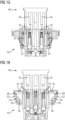
- FIG 4 is a perspective view of the electrical socket 10 in the closed state according to the preferred embodiment of the invention.
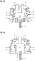
- FIG 12 is a side view of the control element 20 for the electrical socket 10 according to the preferred embodiment of the invention.
- FIG 14 is another perspective view of the two cover elements 16, the two lever elements 22 and the control element 20 for the electrical Socket 10 according to the preferred embodiment of the invention.
- FIG 14 shows the same condition, in particular the same positions of the link pins 26 of the control element 20 in the link guides 24 of the lever elements 26, as in FIGURE 13 , wherein the two cover elements 16, the two lever elements 22 and the control element 20 are shown from the opposite side.
- FIG 18 is a perspective sectional view of the electrical socket 10 in the opened state according to the preferred embodiment of the invention.
Landscapes
- Engineering & Computer Science (AREA)
- Power Engineering (AREA)
- Transportation (AREA)
- Mechanical Engineering (AREA)
- Details Of Connecting Devices For Male And Female Coupling (AREA)
Claims (14)
- Couplage électrique (10), qui peut être couplé à un autre couplage électrique (40), le couplage électrique (10) étant conçu de manière complémentaire à l'autre couplage électrique (40) au moins par zones, et le couplage électrique (10) présentant les éléments suivants :- au moins une douille de contact (12) pour l'introduction d'une broche de contact électrique (42) de l'autre couplage électrique (40),- au moins un élément de contact électrique (18) qui est disposé dans la douille de contact (12) et qui peut être relié électriquement à la broche de contact électrique (42),
et- au moins un élément de recouvrement (16) pour fermer la douille de contact (12) et/ou recouvrir l'élément de contact électrique (18), l'élément de recouvrement (16) étant mobile entre un état fermé et un état ouvert perpendiculairement à la direction d'insertion de la broche de contact électrique (42),
le couplage électrique caractérisé par ,- au moins un élément de commande (20) qui peut être déplacé par l'autre couplage électrique (40) sensiblement parallèlement à la direction d'introduction de la broche de contact électrique (42),- au moins un élément de ressort (32) par lequel l'élément de commande (20) peut être déplacé dans le sens opposé au sens d'insertion de la broche de contact électrique (42), et- un couplage forcé (22, 24, 26, 28, 30) entre l'élément de commande (20) et l'élément de recouvrement (16), de sorte que l'élément de recouvrement (16) peut être déplacé vers l'extérieur tandis que l'autre couplage électrique (40) est couplé au couplage électrique (10). - Couplage électrique (10) selon la revendication 1,
caractérisé en ce que
le couplage électrique (10) est une prise électrique (10) et l'autre couplage électrique (40) est une fiche électrique. - Couplage électrique (10) selon la revendication 1ou 2,
caractérisé en ce que
l'élément de ressort (32) est un ressort de compression (32). - Couplage électrique (10) selon l'une des revendications précédentes,
caractérisé en ce que
le couplage électrique (10) présente au moins un élément de levier (22) qui est relié à l'élément de recouvrement (16) et à un boîtier de le couplage électrique (10) et qui peut pivoter au moyen de l'élément de commande (20). - Couplage électrique (10) selon la revendication 4,
caractérisé en ce que
l'élément de levier (22) est relié par une première articulation (28) à l'élément de recouvrement (16) et par une deuxième articulation (30) au boîtier du couplage électrique (10). - Couplage électrique (10) selon la revendications,
caractérisé en ce que
la première articulation (28) et/ou la deuxième articulation (30) sont conçues comme une articulation à charnière. - Couplage électrique (10) selon l'une des revendications 4 à 6,
caractérisé en ce que
l'élément de levier (22) présente au moins un guidage à coulisse (24) et l'élément de commande (20) au moins un tourillon de coulisse (26), le tourillon de coulisse (26) pénétrant dans le guidage à coulisse (24) et pouvant être déplacé le long du guidage à coulisse (24). - Couplage électrique (10) selon la revendication 7,
caractérisé en ce que
le guide de coulisse (24) est disposé entre la première articulation (28) et la deuxième articulation (30). - Couplage électrique (10) selon la revendication 7 ou 8,
caractérisé en ce que
le guidage à coulisse (24) est réalisé en forme de S, de sorte que le mouvement de l'élément de commande (20) le long de la direction d'introduction de la broche de contact électrique (42) fait pivoter l'élément de levier (22) vers l'extérieur, déplace l'élément de recouvrement (16) vers l'extérieur et ouvre la douille de contact (12). - Couplage électrique (10) selon l'une des revendications 4 à 9,
caractérisé en ce que
deux éléments de levier (22) et deux éléments de recouvrement (16) sont associés à un élément de commande (20). - Couplage électrique (10) selon la revendication 10,
caractérisé en ce que
l'élément de commande (20) est disposé entre les éléments de levier (22). - Couplage électrique (10) selon l'une des revendications précédentes,
caractérisé en ce que
la douille de contact (12) présente une ouverture latérale à travers laquelle l'élément de recouvrement (16) destiné à recouvrir l'élément de contact électrique (18) peut pénétrer ou pénètre dans la douille de contact (12). - Couplage électrique (10) selon l'une des revendications précédentes,
caractérisé en ce que
l'élément de commande (20) présente au moins un ergot de guidage (44) et le couplage électrique (10) au moins un rail de guidage (46) correspondant à l'ergot de guidage (44), l'ergot de guidage (44) étant disposé latéralement devant un côté frontal du rail de guidage (46) lorsque l'élément de recouvrement (16) est fermé, le nez de guidage (44) pouvant être déplacé le long d'un côté longitudinal du rail de guidage (46) lors du mouvement de l'élément de commande (20) parallèlement à la direction d'introduction de la broche de contact électrique (42) et venant buter contre le côté frontal du rail de guidage (46) en cas d'écart dépassant un jeu prédéfini par rapport au mouvement parallèle prévu et empêchant ainsi un autre mouvement de l'élément de commande (20) et donc un mouvement de l'élément de recouvrement (16) dans l'état ouvert. - Système d'embrayage comprenant un couplage électrique (10) selon l'une des revendications 1 à 13 et un autre couplage électrique (40), l'autre couplage électrique (40) étant réalisé au moins par zones de manière complémentaire à le couplage électrique (10), et
dans lequel l'autre couplage électrique (40) comprend au moins un élément d'entraînement qui est prévu pour déplacer l'élément de commande (20) du couplage électrique (10) pendant l'accouplement de l'autre couplage électrique (40) à le couplage électrique (10).
Applications Claiming Priority (1)
| Application Number | Priority Date | Filing Date | Title |
|---|---|---|---|
| DE102020119852.3A DE102020119852A1 (de) | 2020-07-28 | 2020-07-28 | Elektrische Kupplung, insbesondere elektrische Steckdose, die mit einer komplementär ausgebildeten elektrischen Kupplung koppelbar ist |
Publications (2)
| Publication Number | Publication Date |
|---|---|
| EP3945643A1 EP3945643A1 (fr) | 2022-02-02 |
| EP3945643B1 true EP3945643B1 (fr) | 2024-07-10 |
Family
ID=77071322
Family Applications (1)
| Application Number | Title | Priority Date | Filing Date |
|---|---|---|---|
| EP21187843.4A Active EP3945643B1 (fr) | 2020-07-28 | 2021-07-27 | Coupleur électrique pouvant être couplé à un autre coupleur électrique, ainsi que système de couplage comprenant de tels coupleurs électriques |
Country Status (3)
| Country | Link |
|---|---|
| EP (1) | EP3945643B1 (fr) |
| DE (1) | DE102020119852A1 (fr) |
| ES (1) | ES2989973T3 (fr) |
Families Citing this family (1)
| Publication number | Priority date | Publication date | Assignee | Title |
|---|---|---|---|---|
| DE102021122948A1 (de) * | 2021-09-06 | 2023-03-09 | Dr. Ing. H.C. F. Porsche Aktiengesellschaft | Elektrofahrzeug mit einem Ladeklappenmodul |
Family Cites Families (5)
| Publication number | Priority date | Publication date | Assignee | Title |
|---|---|---|---|---|
| US6893275B2 (en) | 2003-01-29 | 2005-05-17 | Koncept Technologies Inc. | Electrical receptacle with shutter |
| DE102009056184B4 (de) | 2008-12-22 | 2012-10-04 | Sumitomo Wiring Systems, Ltd. | Verbinder |
| ES2548186T3 (es) * | 2012-06-14 | 2015-10-14 | Scame Parre S.P.A. | Conexión de corriente industrial de tipo hembra, con dispositivo de protección de los contactos bajo tensión |
| DE102014114214A1 (de) | 2014-09-30 | 2016-03-31 | Phoenix Contact E-Mobility Gmbh | Elektrische Steckdose |
| CN110718803A (zh) * | 2018-07-12 | 2020-01-21 | 东莞崧腾电子有限公司 | 工业插座 |
-
2020
- 2020-07-28 DE DE102020119852.3A patent/DE102020119852A1/de not_active Withdrawn
-
2021
- 2021-07-27 ES ES21187843T patent/ES2989973T3/es active Active
- 2021-07-27 EP EP21187843.4A patent/EP3945643B1/fr active Active
Also Published As
| Publication number | Publication date |
|---|---|
| DE102020119852A1 (de) | 2022-02-03 |
| ES2989973T3 (es) | 2024-11-28 |
| EP3945643A1 (fr) | 2022-02-02 |
Similar Documents
| Publication | Publication Date | Title |
|---|---|---|
| DE69504217T2 (de) | Elektrischer Verbinder mit Lagesicherungsvorrichtung | |
| DE19543009C2 (de) | Verriegelungsmechanismus für ein elektrisches Steckverbinderpaar | |
| EP3176885B1 (fr) | Systeme de connecteur a fiches | |
| EP2325953A1 (fr) | Connecteur à fiche doté d'un connecteur à fiche secondaire | |
| EP3679631B1 (fr) | Connecteur enfichable comprenant des crochets de verrouillage servant à fixer son support de contact dans son boîtier extérieur | |
| EP3476009B1 (fr) | Connecteur | |
| DE102008053137B4 (de) | Steckverbindung, Stromkreis mit Steckverbindung und Betriebsverfahren | |
| WO2020239928A1 (fr) | Connecteur à enfichage avec système de verrouillage | |
| DE102018126469B3 (de) | Federanschlusseinrichtung zum Anschließen eines elektrischen Leiters | |
| DE69904100T2 (de) | Elektrische Sicherheits-Steckverbindung in hermaphroditischer bzw. Zwitterausführung | |
| DE112010002997T5 (de) | Universeller lastschalter | |
| DE112007000611B4 (de) | Elektrischer Steckverbinder und elektrische Steckverbindung mit unterschiedlichen Eingriffs- und operativen Rückhaltekraften | |
| DE2025821A1 (de) | Elektrischer Verbinder | |
| EP2780986B1 (fr) | Connexion enfichable | |
| EP2680374B1 (fr) | Dispositif de connexion | |
| DE69834079T2 (de) | Selbstausrichtender elektrischer Steckerverbinder | |
| WO2020114981A1 (fr) | Ensemble formant connecteur enfichable | |
| DE102017128604A1 (de) | Elektrische Steckverbindung zur Datenübertragung | |
| EP3945643B1 (fr) | Coupleur électrique pouvant être couplé à un autre coupleur électrique, ainsi que système de couplage comprenant de tels coupleurs électriques | |
| DE202020104347U1 (de) | Elektrische Kupplung, insbesondere elektrische Steckdose, die mit einer komplementär ausgebildeten elektrischen Kupplung koppelbar ist | |
| DE10131167A1 (de) | Steckverbinder | |
| DE202004000419U1 (de) | Schraubenlose Leiteranschlussklemme | |
| DE102009014634B4 (de) | Steckverbindung mit geringer Einsteckkraft | |
| DE10304847B4 (de) | Verbinder | |
| EP3261183A1 (fr) | Contact à ressort |
Legal Events
| Date | Code | Title | Description |
|---|---|---|---|
| PUAI | Public reference made under article 153(3) epc to a published international application that has entered the european phase |
Free format text: ORIGINAL CODE: 0009012 |
|
| STAA | Information on the status of an ep patent application or granted ep patent |
Free format text: STATUS: THE APPLICATION HAS BEEN PUBLISHED |
|
| AK | Designated contracting states |
Kind code of ref document: A1 Designated state(s): AL AT BE BG CH CY CZ DE DK EE ES FI FR GB GR HR HU IE IS IT LI LT LU LV MC MK MT NL NO PL PT RO RS SE SI SK SM TR |
|
| STAA | Information on the status of an ep patent application or granted ep patent |
Free format text: STATUS: REQUEST FOR EXAMINATION WAS MADE |
|
| 17P | Request for examination filed |
Effective date: 20220801 |
|
| RBV | Designated contracting states (corrected) |
Designated state(s): AL AT BE BG CH CY CZ DE DK EE ES FI FR GB GR HR HU IE IS IT LI LT LU LV MC MK MT NL NO PL PT RO RS SE SI SK SM TR |
|
| GRAP | Despatch of communication of intention to grant a patent |
Free format text: ORIGINAL CODE: EPIDOSNIGR1 |
|
| STAA | Information on the status of an ep patent application or granted ep patent |
Free format text: STATUS: GRANT OF PATENT IS INTENDED |
|
| INTG | Intention to grant announced |
Effective date: 20240207 |
|
| GRAS | Grant fee paid |
Free format text: ORIGINAL CODE: EPIDOSNIGR3 |
|
| GRAA | (expected) grant |
Free format text: ORIGINAL CODE: 0009210 |
|
| STAA | Information on the status of an ep patent application or granted ep patent |
Free format text: STATUS: THE PATENT HAS BEEN GRANTED |
|
| AK | Designated contracting states |
Kind code of ref document: B1 Designated state(s): AL AT BE BG CH CY CZ DE DK EE ES FI FR GB GR HR HU IE IS IT LI LT LU LV MC MK MT NL NO PL PT RO RS SE SI SK SM TR |
|
| REG | Reference to a national code |
Ref country code: CH Ref legal event code: EP |
|
| REG | Reference to a national code |
Ref country code: DE Ref legal event code: R096 Ref document number: 502021004294 Country of ref document: DE |
|
| RAP2 | Party data changed (patent owner data changed or rights of a patent transferred) |
Owner name: ABL GMBH |
|
| PGFP | Annual fee paid to national office [announced via postgrant information from national office to epo] |
Ref country code: FR Payment date: 20240930 Year of fee payment: 5 |
|
| REG | Reference to a national code |
Ref country code: LT Ref legal event code: MG9D |
|
| REG | Reference to a national code |
Ref country code: NL Ref legal event code: MP Effective date: 20240710 |
|
| REG | Reference to a national code |
Ref country code: ES Ref legal event code: FG2A Ref document number: 2989973 Country of ref document: ES Kind code of ref document: T3 Effective date: 20241128 |
|
| PG25 | Lapsed in a contracting state [announced via postgrant information from national office to epo] |
Ref country code: PT Free format text: LAPSE BECAUSE OF FAILURE TO SUBMIT A TRANSLATION OF THE DESCRIPTION OR TO PAY THE FEE WITHIN THE PRESCRIBED TIME-LIMIT Effective date: 20241111 |
|
| PG25 | Lapsed in a contracting state [announced via postgrant information from national office to epo] |
Ref country code: NL Free format text: LAPSE BECAUSE OF FAILURE TO SUBMIT A TRANSLATION OF THE DESCRIPTION OR TO PAY THE FEE WITHIN THE PRESCRIBED TIME-LIMIT Effective date: 20240710 |
|
| PG25 | Lapsed in a contracting state [announced via postgrant information from national office to epo] |
Ref country code: PT Free format text: LAPSE BECAUSE OF FAILURE TO SUBMIT A TRANSLATION OF THE DESCRIPTION OR TO PAY THE FEE WITHIN THE PRESCRIBED TIME-LIMIT Effective date: 20241111 Ref country code: NL Free format text: LAPSE BECAUSE OF FAILURE TO SUBMIT A TRANSLATION OF THE DESCRIPTION OR TO PAY THE FEE WITHIN THE PRESCRIBED TIME-LIMIT Effective date: 20240710 |
|
| PG25 | Lapsed in a contracting state [announced via postgrant information from national office to epo] |
Ref country code: NO Free format text: LAPSE BECAUSE OF FAILURE TO SUBMIT A TRANSLATION OF THE DESCRIPTION OR TO PAY THE FEE WITHIN THE PRESCRIBED TIME-LIMIT Effective date: 20241010 |
|
| PG25 | Lapsed in a contracting state [announced via postgrant information from national office to epo] |
Ref country code: GR Free format text: LAPSE BECAUSE OF FAILURE TO SUBMIT A TRANSLATION OF THE DESCRIPTION OR TO PAY THE FEE WITHIN THE PRESCRIBED TIME-LIMIT Effective date: 20241011 Ref country code: FI Free format text: LAPSE BECAUSE OF FAILURE TO SUBMIT A TRANSLATION OF THE DESCRIPTION OR TO PAY THE FEE WITHIN THE PRESCRIBED TIME-LIMIT Effective date: 20240710 Ref country code: PL Free format text: LAPSE BECAUSE OF FAILURE TO SUBMIT A TRANSLATION OF THE DESCRIPTION OR TO PAY THE FEE WITHIN THE PRESCRIBED TIME-LIMIT Effective date: 20240710 |
|
| PG25 | Lapsed in a contracting state [announced via postgrant information from national office to epo] |
Ref country code: BG Free format text: LAPSE BECAUSE OF FAILURE TO SUBMIT A TRANSLATION OF THE DESCRIPTION OR TO PAY THE FEE WITHIN THE PRESCRIBED TIME-LIMIT Effective date: 20240710 |
|
| PG25 | Lapsed in a contracting state [announced via postgrant information from national office to epo] |
Ref country code: LV Free format text: LAPSE BECAUSE OF FAILURE TO SUBMIT A TRANSLATION OF THE DESCRIPTION OR TO PAY THE FEE WITHIN THE PRESCRIBED TIME-LIMIT Effective date: 20240710 |
|
| PG25 | Lapsed in a contracting state [announced via postgrant information from national office to epo] |
Ref country code: IS Free format text: LAPSE BECAUSE OF FAILURE TO SUBMIT A TRANSLATION OF THE DESCRIPTION OR TO PAY THE FEE WITHIN THE PRESCRIBED TIME-LIMIT Effective date: 20241110 |
|
| PG25 | Lapsed in a contracting state [announced via postgrant information from national office to epo] |
Ref country code: HR Free format text: LAPSE BECAUSE OF FAILURE TO SUBMIT A TRANSLATION OF THE DESCRIPTION OR TO PAY THE FEE WITHIN THE PRESCRIBED TIME-LIMIT Effective date: 20240710 |
|
| PG25 | Lapsed in a contracting state [announced via postgrant information from national office to epo] |
Ref country code: RS Free format text: LAPSE BECAUSE OF FAILURE TO SUBMIT A TRANSLATION OF THE DESCRIPTION OR TO PAY THE FEE WITHIN THE PRESCRIBED TIME-LIMIT Effective date: 20241010 |
|
| PG25 | Lapsed in a contracting state [announced via postgrant information from national office to epo] |
Ref country code: RS Free format text: LAPSE BECAUSE OF FAILURE TO SUBMIT A TRANSLATION OF THE DESCRIPTION OR TO PAY THE FEE WITHIN THE PRESCRIBED TIME-LIMIT Effective date: 20241010 Ref country code: PL Free format text: LAPSE BECAUSE OF FAILURE TO SUBMIT A TRANSLATION OF THE DESCRIPTION OR TO PAY THE FEE WITHIN THE PRESCRIBED TIME-LIMIT Effective date: 20240710 Ref country code: NO Free format text: LAPSE BECAUSE OF FAILURE TO SUBMIT A TRANSLATION OF THE DESCRIPTION OR TO PAY THE FEE WITHIN THE PRESCRIBED TIME-LIMIT Effective date: 20241010 Ref country code: LV Free format text: LAPSE BECAUSE OF FAILURE TO SUBMIT A TRANSLATION OF THE DESCRIPTION OR TO PAY THE FEE WITHIN THE PRESCRIBED TIME-LIMIT Effective date: 20240710 Ref country code: IS Free format text: LAPSE BECAUSE OF FAILURE TO SUBMIT A TRANSLATION OF THE DESCRIPTION OR TO PAY THE FEE WITHIN THE PRESCRIBED TIME-LIMIT Effective date: 20241110 Ref country code: HR Free format text: LAPSE BECAUSE OF FAILURE TO SUBMIT A TRANSLATION OF THE DESCRIPTION OR TO PAY THE FEE WITHIN THE PRESCRIBED TIME-LIMIT Effective date: 20240710 Ref country code: GR Free format text: LAPSE BECAUSE OF FAILURE TO SUBMIT A TRANSLATION OF THE DESCRIPTION OR TO PAY THE FEE WITHIN THE PRESCRIBED TIME-LIMIT Effective date: 20241011 Ref country code: FI Free format text: LAPSE BECAUSE OF FAILURE TO SUBMIT A TRANSLATION OF THE DESCRIPTION OR TO PAY THE FEE WITHIN THE PRESCRIBED TIME-LIMIT Effective date: 20240710 Ref country code: BG Free format text: LAPSE BECAUSE OF FAILURE TO SUBMIT A TRANSLATION OF THE DESCRIPTION OR TO PAY THE FEE WITHIN THE PRESCRIBED TIME-LIMIT Effective date: 20240710 |
|
| REG | Reference to a national code |
Ref country code: CH Ref legal event code: PL |
|
| PG25 | Lapsed in a contracting state [announced via postgrant information from national office to epo] |
Ref country code: LU Free format text: LAPSE BECAUSE OF NON-PAYMENT OF DUE FEES Effective date: 20240727 |
|
| PG25 | Lapsed in a contracting state [announced via postgrant information from national office to epo] |
Ref country code: LU Free format text: LAPSE BECAUSE OF NON-PAYMENT OF DUE FEES Effective date: 20240727 |
|
| REG | Reference to a national code |
Ref country code: DE Ref legal event code: R097 Ref document number: 502021004294 Country of ref document: DE |
|
| PG25 | Lapsed in a contracting state [announced via postgrant information from national office to epo] |
Ref country code: RO Free format text: LAPSE BECAUSE OF FAILURE TO SUBMIT A TRANSLATION OF THE DESCRIPTION OR TO PAY THE FEE WITHIN THE PRESCRIBED TIME-LIMIT Effective date: 20240710 Ref country code: SM Free format text: LAPSE BECAUSE OF FAILURE TO SUBMIT A TRANSLATION OF THE DESCRIPTION OR TO PAY THE FEE WITHIN THE PRESCRIBED TIME-LIMIT Effective date: 20240710 Ref country code: DK Free format text: LAPSE BECAUSE OF FAILURE TO SUBMIT A TRANSLATION OF THE DESCRIPTION OR TO PAY THE FEE WITHIN THE PRESCRIBED TIME-LIMIT Effective date: 20240710 |
|
| PG25 | Lapsed in a contracting state [announced via postgrant information from national office to epo] |
Ref country code: EE Free format text: LAPSE BECAUSE OF FAILURE TO SUBMIT A TRANSLATION OF THE DESCRIPTION OR TO PAY THE FEE WITHIN THE PRESCRIBED TIME-LIMIT Effective date: 20240710 Ref country code: MC Free format text: LAPSE BECAUSE OF FAILURE TO SUBMIT A TRANSLATION OF THE DESCRIPTION OR TO PAY THE FEE WITHIN THE PRESCRIBED TIME-LIMIT Effective date: 20240710 Ref country code: BE Free format text: LAPSE BECAUSE OF NON-PAYMENT OF DUE FEES Effective date: 20240731 Ref country code: CH Free format text: LAPSE BECAUSE OF NON-PAYMENT OF DUE FEES Effective date: 20240731 |
|
| PG25 | Lapsed in a contracting state [announced via postgrant information from national office to epo] |
Ref country code: CZ Free format text: LAPSE BECAUSE OF FAILURE TO SUBMIT A TRANSLATION OF THE DESCRIPTION OR TO PAY THE FEE WITHIN THE PRESCRIBED TIME-LIMIT Effective date: 20240710 |
|
| PG25 | Lapsed in a contracting state [announced via postgrant information from national office to epo] |
Ref country code: SK Free format text: LAPSE BECAUSE OF FAILURE TO SUBMIT A TRANSLATION OF THE DESCRIPTION OR TO PAY THE FEE WITHIN THE PRESCRIBED TIME-LIMIT Effective date: 20240710 |
|
| PLBE | No opposition filed within time limit |
Free format text: ORIGINAL CODE: 0009261 |
|
| STAA | Information on the status of an ep patent application or granted ep patent |
Free format text: STATUS: NO OPPOSITION FILED WITHIN TIME LIMIT |
|
| REG | Reference to a national code |
Ref country code: BE Ref legal event code: MM Effective date: 20240731 |
|
| 26N | No opposition filed |
Effective date: 20250411 |
|
| PG25 | Lapsed in a contracting state [announced via postgrant information from national office to epo] |
Ref country code: IE Free format text: LAPSE BECAUSE OF NON-PAYMENT OF DUE FEES Effective date: 20240727 |
|
| PG25 | Lapsed in a contracting state [announced via postgrant information from national office to epo] |
Ref country code: SE Free format text: LAPSE BECAUSE OF FAILURE TO SUBMIT A TRANSLATION OF THE DESCRIPTION OR TO PAY THE FEE WITHIN THE PRESCRIBED TIME-LIMIT Effective date: 20240710 |
|
| PGFP | Annual fee paid to national office [announced via postgrant information from national office to epo] |
Ref country code: AT Payment date: 20251020 Year of fee payment: 5 |
|
| PG25 | Lapsed in a contracting state [announced via postgrant information from national office to epo] |
Ref country code: CY Free format text: LAPSE BECAUSE OF FAILURE TO SUBMIT A TRANSLATION OF THE DESCRIPTION OR TO PAY THE FEE WITHIN THE PRESCRIBED TIME-LIMIT; INVALID AB INITIO Effective date: 20210727 |
|
| PG25 | Lapsed in a contracting state [announced via postgrant information from national office to epo] |
Ref country code: HU Free format text: LAPSE BECAUSE OF FAILURE TO SUBMIT A TRANSLATION OF THE DESCRIPTION OR TO PAY THE FEE WITHIN THE PRESCRIBED TIME-LIMIT; INVALID AB INITIO Effective date: 20210727 |
|
| GBPC | Gb: european patent ceased through non-payment of renewal fee |
Effective date: 20250727 |
|
| PG25 | Lapsed in a contracting state [announced via postgrant information from national office to epo] |
Ref country code: GB Free format text: LAPSE BECAUSE OF NON-PAYMENT OF DUE FEES Effective date: 20250727 |
|
| PGFP | Annual fee paid to national office [announced via postgrant information from national office to epo] |
Ref country code: ES Payment date: 20260122 Year of fee payment: 5 |
|
| PGFP | Annual fee paid to national office [announced via postgrant information from national office to epo] |
Ref country code: DE Payment date: 20260112 Year of fee payment: 5 |
|
| PGFP | Annual fee paid to national office [announced via postgrant information from national office to epo] |
Ref country code: IT Payment date: 20260123 Year of fee payment: 5 |