EP3945645A1 - Connecteur électrique coaxial - Google Patents
Connecteur électrique coaxial Download PDFInfo
- Publication number
- EP3945645A1 EP3945645A1 EP21186700.7A EP21186700A EP3945645A1 EP 3945645 A1 EP3945645 A1 EP 3945645A1 EP 21186700 A EP21186700 A EP 21186700A EP 3945645 A1 EP3945645 A1 EP 3945645A1
- Authority
- EP
- European Patent Office
- Prior art keywords
- terminal
- ridges
- electrical connector
- indentations
- preform
- Prior art date
- Legal status (The legal status is an assumption and is not a legal conclusion. Google has not performed a legal analysis and makes no representation as to the accuracy of the status listed.)
- Granted
Links
Images



Classifications
-
- H—ELECTRICITY
- H01—ELECTRIC ELEMENTS
- H01R—ELECTRICALLY-CONDUCTIVE CONNECTIONS; STRUCTURAL ASSOCIATIONS OF A PLURALITY OF MUTUALLY-INSULATED ELECTRICAL CONNECTING ELEMENTS; COUPLING DEVICES; CURRENT COLLECTORS
- H01R24/00—Two-part coupling devices, or either of their cooperating parts, characterised by their overall structure
- H01R24/38—Two-part coupling devices, or either of their cooperating parts, characterised by their overall structure having concentrically or coaxially arranged contacts
- H01R24/40—Two-part coupling devices, or either of their cooperating parts, characterised by their overall structure having concentrically or coaxially arranged contacts specially adapted for high frequency
-
- H—ELECTRICITY
- H01—ELECTRIC ELEMENTS
- H01R—ELECTRICALLY-CONDUCTIVE CONNECTIONS; STRUCTURAL ASSOCIATIONS OF A PLURALITY OF MUTUALLY-INSULATED ELECTRICAL CONNECTING ELEMENTS; COUPLING DEVICES; CURRENT COLLECTORS
- H01R24/00—Two-part coupling devices, or either of their cooperating parts, characterised by their overall structure
- H01R24/38—Two-part coupling devices, or either of their cooperating parts, characterised by their overall structure having concentrically or coaxially arranged contacts
- H01R24/40—Two-part coupling devices, or either of their cooperating parts, characterised by their overall structure having concentrically or coaxially arranged contacts specially adapted for high frequency
- H01R24/56—Two-part coupling devices, or either of their cooperating parts, characterised by their overall structure having concentrically or coaxially arranged contacts specially adapted for high frequency specially adapted to a specific shape of cables, e.g. corrugated cables, twisted pair cables, cables with two screens or hollow cables
-
- H—ELECTRICITY
- H01—ELECTRIC ELEMENTS
- H01R—ELECTRICALLY-CONDUCTIVE CONNECTIONS; STRUCTURAL ASSOCIATIONS OF A PLURALITY OF MUTUALLY-INSULATED ELECTRICAL CONNECTING ELEMENTS; COUPLING DEVICES; CURRENT COLLECTORS
- H01R9/00—Structural associations of a plurality of mutually-insulated electrical connecting elements, e.g. terminal strips or terminal blocks; Terminals or binding posts mounted upon a base or in a case; Bases therefor
- H01R9/03—Connectors arranged to contact a plurality of the conductors of a multiconductor cable, e.g. tapping connections
- H01R9/05—Connectors arranged to contact a plurality of the conductors of a multiconductor cable, e.g. tapping connections for coaxial cables
-
- H—ELECTRICITY
- H01—ELECTRIC ELEMENTS
- H01R—ELECTRICALLY-CONDUCTIVE CONNECTIONS; STRUCTURAL ASSOCIATIONS OF A PLURALITY OF MUTUALLY-INSULATED ELECTRICAL CONNECTING ELEMENTS; COUPLING DEVICES; CURRENT COLLECTORS
- H01R13/00—Details of coupling devices of the kinds covered by groups H01R12/70 or H01R24/00 - H01R33/00
- H01R13/648—Protective earth or shield arrangements on coupling devices, e.g. anti-static shielding
- H01R13/658—High frequency shielding arrangements, e.g. against EMI [Electro-Magnetic Interference] or EMP [Electro-Magnetic Pulse]
- H01R13/6581—Shield structure
-
- H—ELECTRICITY
- H01—ELECTRIC ELEMENTS
- H01R—ELECTRICALLY-CONDUCTIVE CONNECTIONS; STRUCTURAL ASSOCIATIONS OF A PLURALITY OF MUTUALLY-INSULATED ELECTRICAL CONNECTING ELEMENTS; COUPLING DEVICES; CURRENT COLLECTORS
- H01R43/00—Apparatus or processes specially adapted for manufacturing, assembling, maintaining, or repairing of line connectors or current collectors or for joining electric conductors
- H01R43/16—Apparatus or processes specially adapted for manufacturing, assembling, maintaining, or repairing of line connectors or current collectors or for joining electric conductors for manufacturing contact members, e.g. by punching and by bending
-
- H—ELECTRICITY
- H01—ELECTRIC ELEMENTS
- H01R—ELECTRICALLY-CONDUCTIVE CONNECTIONS; STRUCTURAL ASSOCIATIONS OF A PLURALITY OF MUTUALLY-INSULATED ELECTRICAL CONNECTING ELEMENTS; COUPLING DEVICES; CURRENT COLLECTORS
- H01R43/00—Apparatus or processes specially adapted for manufacturing, assembling, maintaining, or repairing of line connectors or current collectors or for joining electric conductors
- H01R43/28—Apparatus or processes specially adapted for manufacturing, assembling, maintaining, or repairing of line connectors or current collectors or for joining electric conductors for wire processing before connecting to contact members, not provided for in groups H01R43/02 - H01R43/26
-
- H—ELECTRICITY
- H01—ELECTRIC ELEMENTS
- H01R—ELECTRICALLY-CONDUCTIVE CONNECTIONS; STRUCTURAL ASSOCIATIONS OF A PLURALITY OF MUTUALLY-INSULATED ELECTRICAL CONNECTING ELEMENTS; COUPLING DEVICES; CURRENT COLLECTORS
- H01R2103/00—Two poles
-
- H—ELECTRICITY
- H01—ELECTRIC ELEMENTS
- H01R—ELECTRICALLY-CONDUCTIVE CONNECTIONS; STRUCTURAL ASSOCIATIONS OF A PLURALITY OF MUTUALLY-INSULATED ELECTRICAL CONNECTING ELEMENTS; COUPLING DEVICES; CURRENT COLLECTORS
- H01R2201/00—Connectors or connections adapted for particular applications
- H01R2201/26—Connectors or connections adapted for particular applications for vehicles
Definitions
- the invention generally relates to electrical connectors and more particularly to an electrical connector suited for use with coaxial cables.
- Coaxial cable connector assemblies have been used for numerous automotive applications, such as navigation systems, infotainment systems, air bag systems, and other data transmission systems.
- Coaxial cables typically consist of an outer shield conductor, an inner center conductor, a dielectric, and an insulation jacket. The outer conductor and the inner conductor of the coaxial cable often electrically interface with a mating coaxial cable through a coaxial connector.
- Coaxial connectors are often used to connect coaxial cables while providing a certain degree of radio frequency (RF) shielding.
- RF radio frequency
- coaxial connectors for automotive usage has become so common that standards for signal loss and contact resistance have been devised.
- Some coaxial connectors that meet these specifications use high cost cold drawn tubular shield terminals.
- Lower cost stamped male shield terminals and female shield terminals are also used; however, these shield terminals have generally provided less effective shielding due to the limited contact points between the shield terminals provided by cantilevered contact springs, contact bumps on the shield terminals, or a separate contact spring inserted between the shield terminals.
- Coaxial connectors also need to be properly seated to provide adequate shielding i.e., improper seating or air gaps between shield terminals can cause significant RF leakage.
- these coaxial connectors require strict manufacturing tolerances to assure proper seating which drives costs up of each coaxial connector.
- a modern automobile may have over forty of such coaxial connectors.
- an electrical connector includes a terminal having a first surface defining a plurality of ridges protruding from the first surface.
- a first ridge in the plurality of ridges has a different height above the first surface than a second ridge in the plurality of ridges.
- the plurality of ridges is configured to provide a plurality of electrical contact points between the terminal and a corresponding mating terminal.
- the first surface defines a plurality of indentations recessed below the first surface.
- the plurality of ridges is arranged on perimeters of the plurality of indentations.
- the plurality of ridges is formed by material displaced from the plurality of indentations.
- the first surface is curved.
- the first surface has a generally cylindrical shape.
- the first surface does not define an aperture extending therethrough.
- the first surface is an outer surface.
- the terminal is an inner shield terminal.
- the first surface defines an outer surface of the inner shield terminal.
- the corresponding mating terminal is an outer shield terminal having an inner surface and configured to receive the inner shield terminal within.
- At least a portion of the plurality of ridges are in an interface fit with the inner surface when the inner shield terminal is disposed within the outer shield terminal.
- the first surface defines a slit extending longitudinally along a length of the first surface and wherein the first surface is configured to exert a spring force against the inner surface of the outer shield terminal.
- method of manufacturing an electrical connector includes the step of providing a terminal preform formed of sheet metal.
- the terminal preform has a first surface.
- the method also includes the step of forming a plurality of ridges in the first surface which protrude from the first surface.
- a first ridge in the plurality of ridges has a different height above the first surface than a second ridge in the plurality of ridges.
- the plurality of ridges is formed by a knurling process.
- the method further includes the step of forming a plurality of indentations in the first surface that are recessed below the first surface.
- the plurality of ridges and the plurality of indentations are simultaneously formed by the knurling process.
- the method further includes the step of arranging the plurality of ridges between the first surface and the plurality of indentations.
- the method further includes the step of arranging the plurality of ridges on perimeters of the plurality of indentations.
- the plurality of ridges is formed by material of the terminal preform displaced from the plurality of indentations by the knurling process.
- the method further includes the step of bending the terminal preform such that the first surface has a generally cylindrical shape.
- the method further includes the step of bending the terminal preform such that edges of the first surface define a slit extending longitudinally along a length of the first surface.
- an electrical connector is provided.
- the electrical connector includes a terminal having means for providing a plurality of contact points between the terminal and a corresponding mating terminal.
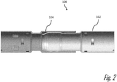
- Figs. 1 and 2 illustrate an example of a coaxial connector assembly, hereinafter referred to as the assembly 100, configured to interconnect two coaxial cables.
- the assembly 100 includes a male electromagnetic shield terminal, hereinafter referred to as the terminal 102, that is configured to be attached to the outer shield conductor of a first coaxial cable (not shown) and female electromagnetic shield terminal, hereinafter referred to as the mating terminal 104, that is configured to be attached to the outer shield conductor of a second coaxial cable (not shown) and to receive the terminal 102.
- the terminal 102 and the mating terminal 104 are configured to surround inner terminals (not shown) attached to inner conductors of the first and second coaxial cables and provide shielding continuity between the first and second coaxial cables.
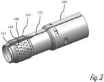
- the terminal 102 has a generally cylindrical shape that is formed by bending or rolling a terminal preform 106 made of sheet metal.
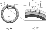
- a first surface, hereafter referred to as the outer surface 108 of a contact portion 110 of the terminal 102 defines a plurality of ridges 112 and indentations 114 in the outer surface 108 that are formed by a knurling process performed on the terminal preform 106 prior to bending the terminal preform 106 into the cylindrical shape.
- the ridges 112 are arranged on the perimeter 116 of the indentations 114.
- the ridges 112 are configured to provide a plurality of electrical contact points between the terminal 102 and the mating terminal 104.
- the indentations 114 and ridges 112 have a rhombic shape, i.e., are in the shape of a rhombus.
- the ridges 112 protrude above the outer surface 108 and the indentations 114, are recessed below the outer surface 108. Without subscribing to any particular theory of operation, the ridges 112 are formed by sheet meal material that is displaced as the indentations 114 are formed in the terminal 102 preform by the knurling process. Due to the rhombic shape of the indentations 114, the height of the ridge 112 above the outer surface 108 vary around the perimeter 116 of the indentation 114 due to more material being displaced near the obtuse angled portion 118 of the indentation 114 than at the acute angled portion of the indentation 114. The height of the ridges 112 above the outer surface 108 may also vary due to tolerance variations in the knurling process.
- the terminal 102 When the terminal 102 is received within the mating terminal 104 at least a portion of the ridges 112 on the outer surface 108 of the terminal 102 are in an interface fit with the inner surface 120 of the mating terminal 104.
- the highest ridges 112 of the terminal 102 are in mechanical and electrical contact with the inner surface 120 of the mating terminal 104, thereby providing a plurality of electrical connections between the terminal 102 and the mating terminal 104 which lowers the connection resistance and improves shielding efficiency.
- the ridges 112 protrude from the outer surface 108 at a height that is typically between 0.03 and 0.07 mm.
- the air gap between the terminal 102 and the mating terminal 104 is reduced to less than 0.1 mm, preferably less than 0.08 mm, more preferably less than 0.05 mm and even more preferably 0.03 mm, further improving shieling efficiency.
- the ridges 112 having different height also improve resistance of the assembly 100 to fretting corrosion since higher ridges 112 that may be degraded by fretting are replaced in contact of ridges 112 that had an originally lower height than the initial ridges 112 in contact.
- the indentation 114 may also serve as a repository for corrosion debris so that it does not interfere in the connector between the terminal 102 and the mating terminal 104.
- the terminal 102 defines a slit 122 in the outer surface 108 extending longitudinally along a length of the outer surface 108.
- the terminal 102 is configured such that the slit 122 is narrowed as the terminal 102 is inserted within the mating terminal 104 such that the outer surface 108 of the terminal 102 exerts a normal spring force against the inner surface 120 of the mating terminal 104, thereby providing a lower resistance and more reliable connection between the terminal 102 and the mating terminal 104 which improves shielding effectiveness.
- the width of the slit is reduced to less than 0.1 mm, preferably less than 0.08 mm, and more preferably less than 0.05 mm.
- the slit 122 is the only opening, hole, gap, breach, or aperture in the outer surface 108 of the terminal 102.
- connector assembly 100 of Figs. 3 through 4B are arranged generally parallel or in line with the cables, alternative embodiments of the connector may be envisioned in which one or both terminals are generally arranged in at right angle to the cables. In yet other alternative embodiments of the connector assembly 100 the connector assembly 100 may be configured to be interconnected to conductive traces on a printed circuit board.
- Figs. 3 through 4B has indentions and ridges 112 that define a rhombic shape, alternative embodiments may have other shaped such as square, rectangular, triangular, round, oval, etc.
- a method 200 of manufacturing an electrical connector assembly 100 such as the one described above is illustrated in Fig. 5 and includes the following steps:
- STEP 202 PROVIDE A TERMINAL PREFORM FORMED OF SHEET METAL HAVING A FIRST SURFACE, includes providing a terminal preform 106 formed of sheet metal having a first surface 108 as shown in Fig. 6 ;
- STEP 204 FORM A PLURALITY OF RIDGES IN THE FIRST SURFACE WHICH PROTRUDE FROM THE FIRST SURFACE SUCH THAT A FIRST RIDGE IN THE PLURALITY OF RIDGES HAS A DIFFERENT HEIGHT ABOVE THE FIRST SURFACE THAN A SECOND RIDGE IN THE PLURALITY OF RIDGES, includes forming a plurality of ridges 112 in the first surface 108 which protrude from the first surface 108 using a knurling die 124 having a plurality of protrusions 126 that are pressed into the terminal preform 106 to form the plurality of ridges 112, shown in Figs. 9 and 10.
- the plurality of ridges 112 are formed such that a first ridge 112 in the plurality of ridges 112 has a different height above the first surface 108 than a second ridge 112 in the plurality of ridges 112;
- STEP 206 FORM A PLURALITY OF INDENTATIONS IN THE FIRST SURFACE THAT ARE RECESSED BELOW THE FIRST SURFACE, includes forming a plurality of indentations 114 in the first surface 108 that are recessed below the first surface 108 by the plurality of protrusions 126 of the knurling die 124 that are pressed into the terminal preform 106 to form the plurality of indentations 114;
- STEP 208 ARRANGE THE PLURALITY OF RIDGES BETWEEN THE FIRST SURFACE AND THE PLURALITY OF INDENTATIONS, includes arranging the plurality of ridges 112 so that they are located between the first surface 108 and the plurality of indentations 114;
- STEP 210 ARRANGE THE PLURALITY OF RIDGES ON PERIMETERS OF THE PLURALITY OF INDENTATIONS, includes arranging the plurality of ridges 112 so that they are located on the perimeters of the plurality of indentations 114;
- STEP 212 BEND THE TERMINAL PREFORM SUCH THAT THE FIRST SURFACE HAS A GENERALLY CYLINDRICAL SHAPE, includes bending or rolling the terminal preform 106 such that the first surface 108 has a generally cylindrical shape;
- STEP 214 BEND THE TERMINAL PREFORM SUCH THAT EDGES OF THE FIRST SURFACE DEFINE A SLIT EXTENDING LONGITUDINALLY ALONG A LENGTH OF THE FIRST SURFACE, includes bending the terminal preform 106 such that edges of the first surface 108 define a slit 122 that extends longitudinally along a length of the first surface 108.
- an electrical connector assembly 100 and a method 200 of manufacturing an electrical connector is provided.
- the assembly 100 and the method 200 provide the benefits over the prior art connector assemblies of improved shielding efficiency due to a lower connection resistance and reduced air gap between the terminal 102 and the mating terminal 104.
- the assembly 100 and the method 200 also provide improve resistance of the assembly 100 to fretting corrosion.
- 'one or more' includes a function being performed by one element, a function being performed by more than one element, e.g., in a distributed fashion, several functions being performed by one element, several functions being performed by several elements, or any combination of the above.
- first, second, etc. are, in some instances, used herein to describe various elements, these elements should not be limited by these terms. These terms are only used to distinguish one element from another.
- a first contact could be termed a second contact, and, similarly, a second contact could be termed a first contact, without departing from the scope of the various described embodiments.
- the first contact and the second contact are both contacts, but they are not the same contact.
- the term “if' is, optionally, construed to mean “when” or “upon” or “in response to determining” or “in response to detecting,” depending on the context.
- the phrase “if it is determined” or “if [a stated condition or event] is detected” is, optionally, construed to mean “upon determining” or “in response to determining” or “upon detecting [the stated condition or event]” or “in response to detecting [the stated condition or event],” depending on the context.
Landscapes
- Engineering & Computer Science (AREA)
- Manufacturing & Machinery (AREA)
- Manufacturing Of Electrical Connectors (AREA)
- Details Of Connecting Devices For Male And Female Coupling (AREA)
Applications Claiming Priority (1)
| Application Number | Priority Date | Filing Date | Title |
|---|---|---|---|
| US16/940,619 US11469557B2 (en) | 2020-07-28 | 2020-07-28 | Coaxial electrical connector |
Publications (2)
| Publication Number | Publication Date |
|---|---|
| EP3945645A1 true EP3945645A1 (fr) | 2022-02-02 |
| EP3945645B1 EP3945645B1 (fr) | 2025-03-26 |
Family
ID=76999719
Family Applications (1)
| Application Number | Title | Priority Date | Filing Date |
|---|---|---|---|
| EP21186700.7A Active EP3945645B1 (fr) | 2020-07-28 | 2021-07-20 | Connecteur électrique coaxial |
Country Status (3)
| Country | Link |
|---|---|
| US (1) | US11469557B2 (fr) |
| EP (1) | EP3945645B1 (fr) |
| CN (1) | CN114006188B (fr) |
Families Citing this family (6)
| Publication number | Priority date | Publication date | Assignee | Title |
|---|---|---|---|---|
| US10797412B2 (en) | 2017-11-21 | 2020-10-06 | Amphenol Corporation | High frequency electrical connector |
| US11509075B2 (en) | 2019-11-12 | 2022-11-22 | Amphenol Corporation | High frequency electrical connector |
| US11489300B2 (en) | 2020-02-20 | 2022-11-01 | Amphenol Corporation | Coupling mechanism and connector with the same |
| US11715919B2 (en) | 2020-02-20 | 2023-08-01 | Amphenol Corporation | Coupling mechanism and connector with the same |
| USD993182S1 (en) | 2020-02-20 | 2023-07-25 | Amphenol Corporation | Electrical connector |
| US12431676B2 (en) * | 2023-02-02 | 2025-09-30 | Aptiv Technologies AG | Right angled coaxial electrical connector and method of forming same |
Citations (3)
| Publication number | Priority date | Publication date | Assignee | Title |
|---|---|---|---|---|
| EP0052980A2 (fr) * | 1980-11-26 | 1982-06-02 | AMP INCORPORATED (a New Jersey corporation) | Système à éléments pour un assemblage d'un connecteur coaxial |
| US20110097928A1 (en) * | 2009-10-22 | 2011-04-28 | Donald Andrew Burris | Locking Ratcheting Torque Aid |
| JP5375574B2 (ja) * | 2009-12-11 | 2013-12-25 | 株式会社オートネットワーク技術研究所 | シールドコネクタ |
Family Cites Families (22)
| Publication number | Priority date | Publication date | Assignee | Title |
|---|---|---|---|---|
| FR2806216B1 (fr) | 2000-03-08 | 2003-08-01 | Coutier Moulage Gen Ind | Dispositif de connexion rapide d'un cable a une borne d'une source d'alimentation en energie electrique |
| US6372991B1 (en) | 2000-09-13 | 2002-04-16 | Tektronix, Inc. | Crimpless strain relief termination for a coaxial cable |
| DE10109719C1 (de) * | 2001-02-28 | 2002-10-24 | Harting Automotive Gmbh & Co | Steckverbinder |
| DE10259803B3 (de) | 2002-12-19 | 2004-05-13 | Kathrein-Werke Kg | Elektrische Anschlussverbindung, insbesondere für den Anschluss eines Außenleiters eines Koaxialkabels |
| US7195505B1 (en) * | 2004-11-08 | 2007-03-27 | Oyo Geospace Corporation | Connector assembly |
| US8167636B1 (en) * | 2010-10-15 | 2012-05-01 | John Mezzalingua Associates, Inc. | Connector having a continuity member |
| US8485853B2 (en) | 2011-11-03 | 2013-07-16 | Delphi Technologies, Inc. | Electrical contact having knurl pattern with recessed rhombic elements that each have an axial minor distance |
| DE102011088793A1 (de) * | 2011-12-16 | 2013-06-20 | Tyco Electronics Amp Gmbh | Elektrischer Steckverbinder mit mikrostrukturiertem Kontaktelement |
| US9748683B2 (en) * | 2013-03-29 | 2017-08-29 | Kobe Steel, Ltd. | Electroconductive material superior in resistance to fretting corrosion for connection component |
| US9608427B2 (en) * | 2014-10-13 | 2017-03-28 | Te Connectivity Corporation | Systems and methods for forming a conductive wire assembly |
| JP2016125130A (ja) * | 2015-01-08 | 2016-07-11 | 株式会社デンソー | 複合材料、複合材料の形成方法、複合材料によってめっきされた電極、および、接続構造 |
| JP2016164836A (ja) * | 2015-03-06 | 2016-09-08 | 株式会社オートネットワーク技術研究所 | 端子付き電線及び端子 |
| US10532628B2 (en) | 2015-05-05 | 2020-01-14 | Mahle International Gmbh | HVAC module having a reconfigurable bi-level duct system |
| US20160344127A1 (en) * | 2015-05-20 | 2016-11-24 | Delphi Technologies, Inc. | Electroconductive material with an undulating surface, an electrical terminal formed of said material, and a method of producing said material |
| EP3096404A1 (fr) * | 2015-05-21 | 2016-11-23 | Delphi Technologies, Inc. | Système de connexion par sertissage pour câbles électriques, comprenant un manchon de fixation |
| US9673578B1 (en) * | 2016-05-06 | 2017-06-06 | Te Connectivity Corporation | Cable-mounted electrical connector |
| US9667000B1 (en) * | 2016-06-09 | 2017-05-30 | Delphi Technologies, Inc. | Radio frequency coaxial connector assembly and method of manufacturing same |
| EP3396793B1 (fr) * | 2017-04-28 | 2020-08-26 | Rosenberger Hochfrequenztechnik GmbH & Co. KG | Corps de contact pour connecteur à fiche |
| US10516238B2 (en) * | 2017-06-08 | 2019-12-24 | Delphi Technologies, Llc | Method for forming a shielded electrical terminal and an electrical terminal formed by said method |
| US10283898B2 (en) * | 2017-09-08 | 2019-05-07 | Apple Inc. | Electronic device enclosures having a monolithic appearance |
| US10177517B1 (en) * | 2018-05-15 | 2019-01-08 | Aptiv Technologies Limited | Ferrule crimping tool |
| US10741975B2 (en) * | 2018-10-19 | 2020-08-11 | Aptiv Technologies Limited | Sheilded cable assembly and electromagnetic shield terminal assembly for same |
-
2020
- 2020-07-28 US US16/940,619 patent/US11469557B2/en active Active
-
2021
- 2021-07-20 EP EP21186700.7A patent/EP3945645B1/fr active Active
- 2021-07-27 CN CN202110849972.8A patent/CN114006188B/zh active Active
Patent Citations (3)
| Publication number | Priority date | Publication date | Assignee | Title |
|---|---|---|---|---|
| EP0052980A2 (fr) * | 1980-11-26 | 1982-06-02 | AMP INCORPORATED (a New Jersey corporation) | Système à éléments pour un assemblage d'un connecteur coaxial |
| US20110097928A1 (en) * | 2009-10-22 | 2011-04-28 | Donald Andrew Burris | Locking Ratcheting Torque Aid |
| JP5375574B2 (ja) * | 2009-12-11 | 2013-12-25 | 株式会社オートネットワーク技術研究所 | シールドコネクタ |
Also Published As
| Publication number | Publication date |
|---|---|
| US11469557B2 (en) | 2022-10-11 |
| US20220037841A1 (en) | 2022-02-03 |
| CN114006188A (zh) | 2022-02-01 |
| EP3945645B1 (fr) | 2025-03-26 |
| CN114006188B (zh) | 2025-09-26 |
Similar Documents
| Publication | Publication Date | Title |
|---|---|---|
| US11469557B2 (en) | Coaxial electrical connector | |
| EP3787125B1 (fr) | Ensemble connecteur électrique blindé et méthode fabrication associée | |
| US10886668B1 (en) | Coaxial cable connector assembly | |
| US7597563B2 (en) | Conducting member and connector having conducting member | |
| US7232344B1 (en) | High speed, card edge connector | |
| EP0112144B1 (fr) | Connecteur électrique pour câble plat et flexible | |
| JP2018026323A (ja) | 無線周波数同軸コネクタアセンブリおよび当該アセンブリの製造方法 | |
| CA2291425C (fr) | Connecteur electrique a filtre comprenant des elements de ferrite multiples | |
| US5135417A (en) | Dual usage electrical/electronic pin terminal system | |
| JP3415934B2 (ja) | 電気端子 | |
| CN101953036A (zh) | 电接线端装置 | |
| EP3750215A1 (fr) | Ferrule électrique, unité de connexion électrique ainsi que procédé de pré-assemblage d'un câble électrique | |
| US5078609A (en) | Plural jack connector module | |
| JPH0235423B2 (fr) | ||
| US10290979B2 (en) | Electrical connector assembly | |
| EP2779326B1 (fr) | Connecteur électrique comprenant un shunt et ensemble de deux tels connecteurs | |
| EP4411992A1 (fr) | Connecteur électrique coaxial à angle droit et son procédé de formation | |
| US6341978B1 (en) | Press-connecting terminal | |
| US11705658B2 (en) | Twist-lock electrical connector assembly | |
| US20040002248A1 (en) | Filtered electrical connector | |
| CN109217068B (zh) | 一种卡连接器开关端子的制造工艺 | |
| CN119495982A (zh) | 连接器和连接器组件 | |
| CN117791207A (zh) | 一种压入型端子及电连接组件 |
Legal Events
| Date | Code | Title | Description |
|---|---|---|---|
| PUAI | Public reference made under article 153(3) epc to a published international application that has entered the european phase |
Free format text: ORIGINAL CODE: 0009012 |
|
| STAA | Information on the status of an ep patent application or granted ep patent |
Free format text: STATUS: THE APPLICATION HAS BEEN PUBLISHED |
|
| AK | Designated contracting states |
Kind code of ref document: A1 Designated state(s): AL AT BE BG CH CY CZ DE DK EE ES FI FR GB GR HR HU IE IS IT LI LT LU LV MC MK MT NL NO PL PT RO RS SE SI SK SM TR |
|
| STAA | Information on the status of an ep patent application or granted ep patent |
Free format text: STATUS: REQUEST FOR EXAMINATION WAS MADE |
|
| 17P | Request for examination filed |
Effective date: 20220802 |
|
| RBV | Designated contracting states (corrected) |
Designated state(s): AL AT BE BG CH CY CZ DE DK EE ES FI FR GB GR HR HU IE IS IT LI LT LU LV MC MK MT NL NO PL PT RO RS SE SI SK SM TR |
|
| RAP3 | Party data changed (applicant data changed or rights of an application transferred) |
Owner name: APTIV TECHNOLOGIES LIMITED |
|
| STAA | Information on the status of an ep patent application or granted ep patent |
Free format text: STATUS: EXAMINATION IS IN PROGRESS |
|
| 17Q | First examination report despatched |
Effective date: 20230703 |
|
| RAP1 | Party data changed (applicant data changed or rights of an application transferred) |
Owner name: APTIV TECHNOLOGIES AG |
|
| RAP3 | Party data changed (applicant data changed or rights of an application transferred) |
Owner name: APTIV TECHNOLOGIES AG |
|
| GRAP | Despatch of communication of intention to grant a patent |
Free format text: ORIGINAL CODE: EPIDOSNIGR1 |
|
| STAA | Information on the status of an ep patent application or granted ep patent |
Free format text: STATUS: GRANT OF PATENT IS INTENDED |
|
| INTG | Intention to grant announced |
Effective date: 20250102 |
|
| GRAS | Grant fee paid |
Free format text: ORIGINAL CODE: EPIDOSNIGR3 |
|
| GRAA | (expected) grant |
Free format text: ORIGINAL CODE: 0009210 |
|
| STAA | Information on the status of an ep patent application or granted ep patent |
Free format text: STATUS: THE PATENT HAS BEEN GRANTED |
|
| P01 | Opt-out of the competence of the unified patent court (upc) registered |
Free format text: CASE NUMBER: APP_5795/2025 Effective date: 20250204 |
|
| AK | Designated contracting states |
Kind code of ref document: B1 Designated state(s): AL AT BE BG CH CY CZ DE DK EE ES FI FR GB GR HR HU IE IS IT LI LT LU LV MC MK MT NL NO PL PT RO RS SE SI SK SM TR |
|
| REG | Reference to a national code |
Ref country code: GB Ref legal event code: FG4D |
|
| REG | Reference to a national code |
Ref country code: CH Ref legal event code: EP |
|
| REG | Reference to a national code |
Ref country code: DE Ref legal event code: R096 Ref document number: 602021028041 Country of ref document: DE |
|
| REG | Reference to a national code |
Ref country code: IE Ref legal event code: FG4D |
|
| PG25 | Lapsed in a contracting state [announced via postgrant information from national office to epo] |
Ref country code: RS Free format text: LAPSE BECAUSE OF FAILURE TO SUBMIT A TRANSLATION OF THE DESCRIPTION OR TO PAY THE FEE WITHIN THE PRESCRIBED TIME-LIMIT Effective date: 20250626 |
|
| PG25 | Lapsed in a contracting state [announced via postgrant information from national office to epo] |
Ref country code: FI Free format text: LAPSE BECAUSE OF FAILURE TO SUBMIT A TRANSLATION OF THE DESCRIPTION OR TO PAY THE FEE WITHIN THE PRESCRIBED TIME-LIMIT Effective date: 20250326 |
|
| REG | Reference to a national code |
Ref country code: LT Ref legal event code: MG9D |
|
| PG25 | Lapsed in a contracting state [announced via postgrant information from national office to epo] |
Ref country code: NO Free format text: LAPSE BECAUSE OF FAILURE TO SUBMIT A TRANSLATION OF THE DESCRIPTION OR TO PAY THE FEE WITHIN THE PRESCRIBED TIME-LIMIT Effective date: 20250626 |
|
| PG25 | Lapsed in a contracting state [announced via postgrant information from national office to epo] |
Ref country code: HR Free format text: LAPSE BECAUSE OF FAILURE TO SUBMIT A TRANSLATION OF THE DESCRIPTION OR TO PAY THE FEE WITHIN THE PRESCRIBED TIME-LIMIT Effective date: 20250326 |
|
| PG25 | Lapsed in a contracting state [announced via postgrant information from national office to epo] |
Ref country code: LV Free format text: LAPSE BECAUSE OF FAILURE TO SUBMIT A TRANSLATION OF THE DESCRIPTION OR TO PAY THE FEE WITHIN THE PRESCRIBED TIME-LIMIT Effective date: 20250326 |
|
| PG25 | Lapsed in a contracting state [announced via postgrant information from national office to epo] |
Ref country code: GR Free format text: LAPSE BECAUSE OF FAILURE TO SUBMIT A TRANSLATION OF THE DESCRIPTION OR TO PAY THE FEE WITHIN THE PRESCRIBED TIME-LIMIT Effective date: 20250627 Ref country code: BG Free format text: LAPSE BECAUSE OF FAILURE TO SUBMIT A TRANSLATION OF THE DESCRIPTION OR TO PAY THE FEE WITHIN THE PRESCRIBED TIME-LIMIT Effective date: 20250326 |
|
| REG | Reference to a national code |
Ref country code: NL Ref legal event code: MP Effective date: 20250326 |
|
| PG25 | Lapsed in a contracting state [announced via postgrant information from national office to epo] |
Ref country code: NL Free format text: LAPSE BECAUSE OF FAILURE TO SUBMIT A TRANSLATION OF THE DESCRIPTION OR TO PAY THE FEE WITHIN THE PRESCRIBED TIME-LIMIT Effective date: 20250326 |
|
| PG25 | Lapsed in a contracting state [announced via postgrant information from national office to epo] |
Ref country code: SE Free format text: LAPSE BECAUSE OF FAILURE TO SUBMIT A TRANSLATION OF THE DESCRIPTION OR TO PAY THE FEE WITHIN THE PRESCRIBED TIME-LIMIT Effective date: 20250326 |
|
| REG | Reference to a national code |
Ref country code: AT Ref legal event code: MK05 Ref document number: 1779921 Country of ref document: AT Kind code of ref document: T Effective date: 20250326 |
|
| PG25 | Lapsed in a contracting state [announced via postgrant information from national office to epo] |
Ref country code: SM Free format text: LAPSE BECAUSE OF FAILURE TO SUBMIT A TRANSLATION OF THE DESCRIPTION OR TO PAY THE FEE WITHIN THE PRESCRIBED TIME-LIMIT Effective date: 20250326 |
|
| PG25 | Lapsed in a contracting state [announced via postgrant information from national office to epo] |
Ref country code: ES Free format text: LAPSE BECAUSE OF FAILURE TO SUBMIT A TRANSLATION OF THE DESCRIPTION OR TO PAY THE FEE WITHIN THE PRESCRIBED TIME-LIMIT Effective date: 20250326 Ref country code: PT Free format text: LAPSE BECAUSE OF FAILURE TO SUBMIT A TRANSLATION OF THE DESCRIPTION OR TO PAY THE FEE WITHIN THE PRESCRIBED TIME-LIMIT Effective date: 20250728 |
|
| PGFP | Annual fee paid to national office [announced via postgrant information from national office to epo] |
Ref country code: DE Payment date: 20250618 Year of fee payment: 5 |
|
| PG25 | Lapsed in a contracting state [announced via postgrant information from national office to epo] |
Ref country code: IT Free format text: LAPSE BECAUSE OF FAILURE TO SUBMIT A TRANSLATION OF THE DESCRIPTION OR TO PAY THE FEE WITHIN THE PRESCRIBED TIME-LIMIT Effective date: 20250326 Ref country code: PL Free format text: LAPSE BECAUSE OF FAILURE TO SUBMIT A TRANSLATION OF THE DESCRIPTION OR TO PAY THE FEE WITHIN THE PRESCRIBED TIME-LIMIT Effective date: 20250326 |
|
| PGFP | Annual fee paid to national office [announced via postgrant information from national office to epo] |
Ref country code: GB Payment date: 20250703 Year of fee payment: 5 |
|
| PG25 | Lapsed in a contracting state [announced via postgrant information from national office to epo] |
Ref country code: AT Free format text: LAPSE BECAUSE OF FAILURE TO SUBMIT A TRANSLATION OF THE DESCRIPTION OR TO PAY THE FEE WITHIN THE PRESCRIBED TIME-LIMIT Effective date: 20250326 |
|
| PGFP | Annual fee paid to national office [announced via postgrant information from national office to epo] |
Ref country code: FR Payment date: 20250703 Year of fee payment: 5 |
|
| PG25 | Lapsed in a contracting state [announced via postgrant information from national office to epo] |
Ref country code: EE Free format text: LAPSE BECAUSE OF FAILURE TO SUBMIT A TRANSLATION OF THE DESCRIPTION OR TO PAY THE FEE WITHIN THE PRESCRIBED TIME-LIMIT Effective date: 20250326 |
|
| PG25 | Lapsed in a contracting state [announced via postgrant information from national office to epo] |
Ref country code: RO Free format text: LAPSE BECAUSE OF FAILURE TO SUBMIT A TRANSLATION OF THE DESCRIPTION OR TO PAY THE FEE WITHIN THE PRESCRIBED TIME-LIMIT Effective date: 20250326 |
|
| PG25 | Lapsed in a contracting state [announced via postgrant information from national office to epo] |
Ref country code: SK Free format text: LAPSE BECAUSE OF FAILURE TO SUBMIT A TRANSLATION OF THE DESCRIPTION OR TO PAY THE FEE WITHIN THE PRESCRIBED TIME-LIMIT Effective date: 20250326 |
|
| PG25 | Lapsed in a contracting state [announced via postgrant information from national office to epo] |
Ref country code: IS Free format text: LAPSE BECAUSE OF FAILURE TO SUBMIT A TRANSLATION OF THE DESCRIPTION OR TO PAY THE FEE WITHIN THE PRESCRIBED TIME-LIMIT Effective date: 20250726 |
|
| REG | Reference to a national code |
Ref country code: DE Ref legal event code: R097 Ref document number: 602021028041 Country of ref document: DE |
|
| PG25 | Lapsed in a contracting state [announced via postgrant information from national office to epo] |
Ref country code: DK Free format text: LAPSE BECAUSE OF FAILURE TO SUBMIT A TRANSLATION OF THE DESCRIPTION OR TO PAY THE FEE WITHIN THE PRESCRIBED TIME-LIMIT Effective date: 20250326 |
|
| PG25 | Lapsed in a contracting state [announced via postgrant information from national office to epo] |
Ref country code: CZ Free format text: LAPSE BECAUSE OF FAILURE TO SUBMIT A TRANSLATION OF THE DESCRIPTION OR TO PAY THE FEE WITHIN THE PRESCRIBED TIME-LIMIT Effective date: 20250326 |
|
| PLBE | No opposition filed within time limit |
Free format text: ORIGINAL CODE: 0009261 |
|
| STAA | Information on the status of an ep patent application or granted ep patent |
Free format text: STATUS: NO OPPOSITION FILED WITHIN TIME LIMIT |
|
| REG | Reference to a national code |
Ref country code: CH Ref legal event code: L10 Free format text: ST27 STATUS EVENT CODE: U-0-0-L10-L00 (AS PROVIDED BY THE NATIONAL OFFICE) Effective date: 20260211 |
|
| REG | Reference to a national code |
Ref country code: CH Ref legal event code: H13 Free format text: ST27 STATUS EVENT CODE: U-0-0-H10-H13 (AS PROVIDED BY THE NATIONAL OFFICE) Effective date: 20260224 |
|
| 26N | No opposition filed |
Effective date: 20260105 |
|
| PG25 | Lapsed in a contracting state [announced via postgrant information from national office to epo] |
Ref country code: LU Free format text: LAPSE BECAUSE OF NON-PAYMENT OF DUE FEES Effective date: 20250720 |
|
| REG | Reference to a national code |
Ref country code: BE Ref legal event code: MM Effective date: 20250731 |
|
| PG25 | Lapsed in a contracting state [announced via postgrant information from national office to epo] |
Ref country code: BE Free format text: LAPSE BECAUSE OF NON-PAYMENT OF DUE FEES Effective date: 20250731 |
|
| PG25 | Lapsed in a contracting state [announced via postgrant information from national office to epo] |
Ref country code: CH Free format text: LAPSE BECAUSE OF NON-PAYMENT OF DUE FEES Effective date: 20250731 |