EP3945665A1 - Système de boîte de vitesses - Google Patents
Système de boîte de vitesses Download PDFInfo
- Publication number
- EP3945665A1 EP3945665A1 EP21184936.9A EP21184936A EP3945665A1 EP 3945665 A1 EP3945665 A1 EP 3945665A1 EP 21184936 A EP21184936 A EP 21184936A EP 3945665 A1 EP3945665 A1 EP 3945665A1
- Authority
- EP
- European Patent Office
- Prior art keywords
- transmission system
- electric
- transmission
- magnetic
- power
- Prior art date
- Legal status (The legal status is an assumption and is not a legal conclusion. Google has not performed a legal analysis and makes no representation as to the accuracy of the status listed.)
- Granted
Links
Images







Classifications
-
- B—PERFORMING OPERATIONS; TRANSPORTING
- B60—VEHICLES IN GENERAL
- B60K—ARRANGEMENT OR MOUNTING OF PROPULSION UNITS OR OF TRANSMISSIONS IN VEHICLES; ARRANGEMENT OR MOUNTING OF PLURAL DIVERSE PRIME-MOVERS IN VEHICLES; AUXILIARY DRIVES FOR VEHICLES; INSTRUMENTATION OR DASHBOARDS FOR VEHICLES; ARRANGEMENTS IN CONNECTION WITH COOLING, AIR INTAKE, GAS EXHAUST OR FUEL SUPPLY OF PROPULSION UNITS IN VEHICLES
- B60K6/00—Arrangement or mounting of plural diverse prime-movers for mutual or common propulsion, e.g. hybrid propulsion systems comprising electric motors and internal combustion engines
- B60K6/20—Arrangement or mounting of plural diverse prime-movers for mutual or common propulsion, e.g. hybrid propulsion systems comprising electric motors and internal combustion engines the prime-movers consisting of electric motors and internal combustion engines, e.g. HEVs
- B60K6/42—Arrangement or mounting of plural diverse prime-movers for mutual or common propulsion, e.g. hybrid propulsion systems comprising electric motors and internal combustion engines the prime-movers consisting of electric motors and internal combustion engines, e.g. HEVs characterised by the architecture of the hybrid electric vehicle
- B60K6/44—Series-parallel type
- B60K6/442—Series-parallel switching type
-
- H—ELECTRICITY
- H02—GENERATION; CONVERSION OR DISTRIBUTION OF ELECTRIC POWER
- H02K—DYNAMO-ELECTRIC MACHINES
- H02K7/00—Arrangements for handling mechanical energy structurally associated with dynamo-electric machines, e.g. structural association with mechanical driving motors or auxiliary dynamo-electric machines
- H02K7/10—Structural association with clutches, brakes, gears, pulleys or mechanical starters
- H02K7/116—Structural association with clutches, brakes, gears, pulleys or mechanical starters with gears
-
- B—PERFORMING OPERATIONS; TRANSPORTING
- B60—VEHICLES IN GENERAL
- B60K—ARRANGEMENT OR MOUNTING OF PROPULSION UNITS OR OF TRANSMISSIONS IN VEHICLES; ARRANGEMENT OR MOUNTING OF PLURAL DIVERSE PRIME-MOVERS IN VEHICLES; AUXILIARY DRIVES FOR VEHICLES; INSTRUMENTATION OR DASHBOARDS FOR VEHICLES; ARRANGEMENTS IN CONNECTION WITH COOLING, AIR INTAKE, GAS EXHAUST OR FUEL SUPPLY OF PROPULSION UNITS IN VEHICLES
- B60K17/00—Arrangement or mounting of transmissions in vehicles
- B60K17/02—Arrangement or mounting of transmissions in vehicles characterised by arrangement, location, or kind of clutch
-
- B—PERFORMING OPERATIONS; TRANSPORTING
- B60—VEHICLES IN GENERAL
- B60K—ARRANGEMENT OR MOUNTING OF PROPULSION UNITS OR OF TRANSMISSIONS IN VEHICLES; ARRANGEMENT OR MOUNTING OF PLURAL DIVERSE PRIME-MOVERS IN VEHICLES; AUXILIARY DRIVES FOR VEHICLES; INSTRUMENTATION OR DASHBOARDS FOR VEHICLES; ARRANGEMENTS IN CONNECTION WITH COOLING, AIR INTAKE, GAS EXHAUST OR FUEL SUPPLY OF PROPULSION UNITS IN VEHICLES
- B60K17/00—Arrangement or mounting of transmissions in vehicles
- B60K17/04—Arrangement or mounting of transmissions in vehicles characterised by arrangement, location or kind of gearing
- B60K17/06—Arrangement or mounting of transmissions in vehicles characterised by arrangement, location or kind of gearing of change-speed gearing
- B60K17/08—Arrangement or mounting of transmissions in vehicles characterised by arrangement, location or kind of gearing of change-speed gearing of mechanical type
-
- B—PERFORMING OPERATIONS; TRANSPORTING
- B60—VEHICLES IN GENERAL
- B60K—ARRANGEMENT OR MOUNTING OF PROPULSION UNITS OR OF TRANSMISSIONS IN VEHICLES; ARRANGEMENT OR MOUNTING OF PLURAL DIVERSE PRIME-MOVERS IN VEHICLES; AUXILIARY DRIVES FOR VEHICLES; INSTRUMENTATION OR DASHBOARDS FOR VEHICLES; ARRANGEMENTS IN CONNECTION WITH COOLING, AIR INTAKE, GAS EXHAUST OR FUEL SUPPLY OF PROPULSION UNITS IN VEHICLES
- B60K17/00—Arrangement or mounting of transmissions in vehicles
- B60K17/04—Arrangement or mounting of transmissions in vehicles characterised by arrangement, location or kind of gearing
- B60K17/12—Arrangement or mounting of transmissions in vehicles characterised by arrangement, location or kind of gearing of electric gearing
-
- B—PERFORMING OPERATIONS; TRANSPORTING
- B60—VEHICLES IN GENERAL
- B60K—ARRANGEMENT OR MOUNTING OF PROPULSION UNITS OR OF TRANSMISSIONS IN VEHICLES; ARRANGEMENT OR MOUNTING OF PLURAL DIVERSE PRIME-MOVERS IN VEHICLES; AUXILIARY DRIVES FOR VEHICLES; INSTRUMENTATION OR DASHBOARDS FOR VEHICLES; ARRANGEMENTS IN CONNECTION WITH COOLING, AIR INTAKE, GAS EXHAUST OR FUEL SUPPLY OF PROPULSION UNITS IN VEHICLES
- B60K6/00—Arrangement or mounting of plural diverse prime-movers for mutual or common propulsion, e.g. hybrid propulsion systems comprising electric motors and internal combustion engines
- B60K6/20—Arrangement or mounting of plural diverse prime-movers for mutual or common propulsion, e.g. hybrid propulsion systems comprising electric motors and internal combustion engines the prime-movers consisting of electric motors and internal combustion engines, e.g. HEVs
- B60K6/22—Arrangement or mounting of plural diverse prime-movers for mutual or common propulsion, e.g. hybrid propulsion systems comprising electric motors and internal combustion engines the prime-movers consisting of electric motors and internal combustion engines, e.g. HEVs characterised by apparatus, components or means specially adapted for HEVs
- B60K6/36—Arrangement or mounting of plural diverse prime-movers for mutual or common propulsion, e.g. hybrid propulsion systems comprising electric motors and internal combustion engines the prime-movers consisting of electric motors and internal combustion engines, e.g. HEVs characterised by apparatus, components or means specially adapted for HEVs characterised by the transmission gearings
- B60K6/365—Arrangement or mounting of plural diverse prime-movers for mutual or common propulsion, e.g. hybrid propulsion systems comprising electric motors and internal combustion engines the prime-movers consisting of electric motors and internal combustion engines, e.g. HEVs characterised by apparatus, components or means specially adapted for HEVs characterised by the transmission gearings with the gears having orbital motion
-
- B—PERFORMING OPERATIONS; TRANSPORTING
- B60—VEHICLES IN GENERAL
- B60K—ARRANGEMENT OR MOUNTING OF PROPULSION UNITS OR OF TRANSMISSIONS IN VEHICLES; ARRANGEMENT OR MOUNTING OF PLURAL DIVERSE PRIME-MOVERS IN VEHICLES; AUXILIARY DRIVES FOR VEHICLES; INSTRUMENTATION OR DASHBOARDS FOR VEHICLES; ARRANGEMENTS IN CONNECTION WITH COOLING, AIR INTAKE, GAS EXHAUST OR FUEL SUPPLY OF PROPULSION UNITS IN VEHICLES
- B60K6/00—Arrangement or mounting of plural diverse prime-movers for mutual or common propulsion, e.g. hybrid propulsion systems comprising electric motors and internal combustion engines
- B60K6/20—Arrangement or mounting of plural diverse prime-movers for mutual or common propulsion, e.g. hybrid propulsion systems comprising electric motors and internal combustion engines the prime-movers consisting of electric motors and internal combustion engines, e.g. HEVs
- B60K6/50—Architecture of the driveline characterised by arrangement or kind of transmission units
- B60K6/54—Transmission for changing ratio
-
- F—MECHANICAL ENGINEERING; LIGHTING; HEATING; WEAPONS; BLASTING
- F16—ENGINEERING ELEMENTS AND UNITS; GENERAL MEASURES FOR PRODUCING AND MAINTAINING EFFECTIVE FUNCTIONING OF MACHINES OR INSTALLATIONS; THERMAL INSULATION IN GENERAL
- F16H—GEARING
- F16H37/00—Combinations of mechanical gearings, not provided for in groups F16H1/00 - F16H35/00
-
- H—ELECTRICITY
- H02—GENERATION; CONVERSION OR DISTRIBUTION OF ELECTRIC POWER
- H02K—DYNAMO-ELECTRIC MACHINES
- H02K49/00—Dynamo-electric clutches; Dynamo-electric brakes
- H02K49/10—Dynamo-electric clutches; Dynamo-electric brakes of the permanent-magnet type
- H02K49/102—Magnetic gearings, i.e. assembly of gears, linear or rotary, by which motion is magnetically transferred without physical contact
-
- H—ELECTRICITY
- H02—GENERATION; CONVERSION OR DISTRIBUTION OF ELECTRIC POWER
- H02K—DYNAMO-ELECTRIC MACHINES
- H02K7/00—Arrangements for handling mechanical energy structurally associated with dynamo-electric machines, e.g. structural association with mechanical driving motors or auxiliary dynamo-electric machines
- H02K7/006—Structural association of a motor or generator with the drive train of a motor vehicle
-
- B—PERFORMING OPERATIONS; TRANSPORTING
- B60—VEHICLES IN GENERAL
- B60K—ARRANGEMENT OR MOUNTING OF PROPULSION UNITS OR OF TRANSMISSIONS IN VEHICLES; ARRANGEMENT OR MOUNTING OF PLURAL DIVERSE PRIME-MOVERS IN VEHICLES; AUXILIARY DRIVES FOR VEHICLES; INSTRUMENTATION OR DASHBOARDS FOR VEHICLES; ARRANGEMENTS IN CONNECTION WITH COOLING, AIR INTAKE, GAS EXHAUST OR FUEL SUPPLY OF PROPULSION UNITS IN VEHICLES
- B60K17/00—Arrangement or mounting of transmissions in vehicles
- B60K17/04—Arrangement or mounting of transmissions in vehicles characterised by arrangement, location or kind of gearing
- B60K17/10—Arrangement or mounting of transmissions in vehicles characterised by arrangement, location or kind of gearing of fluid gearing
-
- B—PERFORMING OPERATIONS; TRANSPORTING
- B60—VEHICLES IN GENERAL
- B60K—ARRANGEMENT OR MOUNTING OF PROPULSION UNITS OR OF TRANSMISSIONS IN VEHICLES; ARRANGEMENT OR MOUNTING OF PLURAL DIVERSE PRIME-MOVERS IN VEHICLES; AUXILIARY DRIVES FOR VEHICLES; INSTRUMENTATION OR DASHBOARDS FOR VEHICLES; ARRANGEMENTS IN CONNECTION WITH COOLING, AIR INTAKE, GAS EXHAUST OR FUEL SUPPLY OF PROPULSION UNITS IN VEHICLES
- B60K17/00—Arrangement or mounting of transmissions in vehicles
- B60K17/28—Arrangement or mounting of transmissions in vehicles characterised by arrangement, location, or type of power take-off
-
- B—PERFORMING OPERATIONS; TRANSPORTING
- B60—VEHICLES IN GENERAL
- B60K—ARRANGEMENT OR MOUNTING OF PROPULSION UNITS OR OF TRANSMISSIONS IN VEHICLES; ARRANGEMENT OR MOUNTING OF PLURAL DIVERSE PRIME-MOVERS IN VEHICLES; AUXILIARY DRIVES FOR VEHICLES; INSTRUMENTATION OR DASHBOARDS FOR VEHICLES; ARRANGEMENTS IN CONNECTION WITH COOLING, AIR INTAKE, GAS EXHAUST OR FUEL SUPPLY OF PROPULSION UNITS IN VEHICLES
- B60K1/00—Arrangement or mounting of electrical propulsion units
- B60K2001/001—Arrangement or mounting of electrical propulsion units one motor mounted on a propulsion axle for rotating right and left wheels of this axle
-
- B—PERFORMING OPERATIONS; TRANSPORTING
- B60—VEHICLES IN GENERAL
- B60K—ARRANGEMENT OR MOUNTING OF PROPULSION UNITS OR OF TRANSMISSIONS IN VEHICLES; ARRANGEMENT OR MOUNTING OF PLURAL DIVERSE PRIME-MOVERS IN VEHICLES; AUXILIARY DRIVES FOR VEHICLES; INSTRUMENTATION OR DASHBOARDS FOR VEHICLES; ARRANGEMENTS IN CONNECTION WITH COOLING, AIR INTAKE, GAS EXHAUST OR FUEL SUPPLY OF PROPULSION UNITS IN VEHICLES
- B60K6/00—Arrangement or mounting of plural diverse prime-movers for mutual or common propulsion, e.g. hybrid propulsion systems comprising electric motors and internal combustion engines
- B60K6/20—Arrangement or mounting of plural diverse prime-movers for mutual or common propulsion, e.g. hybrid propulsion systems comprising electric motors and internal combustion engines the prime-movers consisting of electric motors and internal combustion engines, e.g. HEVs
- B60K6/22—Arrangement or mounting of plural diverse prime-movers for mutual or common propulsion, e.g. hybrid propulsion systems comprising electric motors and internal combustion engines the prime-movers consisting of electric motors and internal combustion engines, e.g. HEVs characterised by apparatus, components or means specially adapted for HEVs
- B60K6/26—Arrangement or mounting of plural diverse prime-movers for mutual or common propulsion, e.g. hybrid propulsion systems comprising electric motors and internal combustion engines the prime-movers consisting of electric motors and internal combustion engines, e.g. HEVs characterised by apparatus, components or means specially adapted for HEVs characterised by the motors or the generators
- B60K2006/268—Electric drive motor starts the engine, i.e. used as starter motor
-
- B—PERFORMING OPERATIONS; TRANSPORTING
- B60—VEHICLES IN GENERAL
- B60Y—INDEXING SCHEME RELATING TO ASPECTS CROSS-CUTTING VEHICLE TECHNOLOGY
- B60Y2200/00—Type of vehicle
- B60Y2200/90—Vehicles comprising electric prime movers
- B60Y2200/92—Hybrid vehicles
-
- B—PERFORMING OPERATIONS; TRANSPORTING
- B60—VEHICLES IN GENERAL
- B60Y—INDEXING SCHEME RELATING TO ASPECTS CROSS-CUTTING VEHICLE TECHNOLOGY
- B60Y2400/00—Special features of vehicle units
- B60Y2400/70—Gearings
- B60Y2400/73—Planetary gearings
-
- F—MECHANICAL ENGINEERING; LIGHTING; HEATING; WEAPONS; BLASTING
- F16—ENGINEERING ELEMENTS AND UNITS; GENERAL MEASURES FOR PRODUCING AND MAINTAINING EFFECTIVE FUNCTIONING OF MACHINES OR INSTALLATIONS; THERMAL INSULATION IN GENERAL
- F16H—GEARING
- F16H37/00—Combinations of mechanical gearings, not provided for in groups F16H1/00 - F16H35/00
- F16H37/02—Combinations of mechanical gearings, not provided for in groups F16H1/00 - F16H35/00 comprising essentially only toothed or friction gearings
- F16H37/06—Combinations of mechanical gearings, not provided for in groups F16H1/00 - F16H35/00 comprising essentially only toothed or friction gearings with a plurality of driving or driven shafts; with arrangements for dividing torque between two or more intermediate shafts
- F16H37/08—Combinations of mechanical gearings, not provided for in groups F16H1/00 - F16H35/00 comprising essentially only toothed or friction gearings with a plurality of driving or driven shafts; with arrangements for dividing torque between two or more intermediate shafts with differential gearing
- F16H37/0833—Combinations of mechanical gearings, not provided for in groups F16H1/00 - F16H35/00 comprising essentially only toothed or friction gearings with a plurality of driving or driven shafts; with arrangements for dividing torque between two or more intermediate shafts with differential gearing with arrangements for dividing torque between two or more intermediate shafts, i.e. with two or more internal power paths
- F16H37/084—Combinations of mechanical gearings, not provided for in groups F16H1/00 - F16H35/00 comprising essentially only toothed or friction gearings with a plurality of driving or driven shafts; with arrangements for dividing torque between two or more intermediate shafts with differential gearing with arrangements for dividing torque between two or more intermediate shafts, i.e. with two or more internal power paths at least one power path being a continuously variable transmission, i.e. CVT
- F16H2037/088—Power-split transmissions with summing differentials, with the input of the CVT connected or connectable to the input shaft
- F16H2037/0886—Power-split transmissions with summing differentials, with the input of the CVT connected or connectable to the input shaft with switching means, e.g. to change ranges
-
- Y—GENERAL TAGGING OF NEW TECHNOLOGICAL DEVELOPMENTS; GENERAL TAGGING OF CROSS-SECTIONAL TECHNOLOGIES SPANNING OVER SEVERAL SECTIONS OF THE IPC; TECHNICAL SUBJECTS COVERED BY FORMER USPC CROSS-REFERENCE ART COLLECTIONS [XRACs] AND DIGESTS
- Y02—TECHNOLOGIES OR APPLICATIONS FOR MITIGATION OR ADAPTATION AGAINST CLIMATE CHANGE
- Y02T—CLIMATE CHANGE MITIGATION TECHNOLOGIES RELATED TO TRANSPORTATION
- Y02T10/00—Road transport of goods or passengers
- Y02T10/60—Other road transportation technologies with climate change mitigation effect
- Y02T10/62—Hybrid vehicles
Definitions
- the present invention relates to a transmission system for an agricultural machine.
- a transmission system usually consists of an input shaft, a shiftable transmission and an output shaft. Transmission systems change the input drive power in terms of torque and speed and forward this to the output.
- a transmission system can use manual transmissions or continuously variable transmissions as components.
- Manual transmissions are implemented using power-shiftable clutches that connect different gear stages that are in mesh with one another. This shift point, also known as the load shift point, leads to a change in the speed of the engaged transmission system components, to noise development, wear and tear and an interrupted power flow.
- the transmission system can be implemented as a continuously variable transmission.
- This is implemented using hydraulic variators in order to be able to safely convert higher drive power.
- part of the drive power is converted into hydraulic power on the input side of the continuously variable transmission by means of hydrostats.
- the share of the hydraulic power can be varied by means of the variators.
- On the output side the hydraulic energy is converted back into mechanical energy.
- Most continuously variable transmissions have an output shaft to simplify the structure. At the time of shifting of the transmission system, this requires a speed change at the variator output shaft at the same time as the gear change in the downstream transmission. This process takes time, which slows down the shifting process and causes sluggishness in the transmission system.
- the transmission system can be equipped with a continuously variable transmission with two variator output shafts.
- a simultaneous speed change with the shifting process can be dispensed with.
- This type of design leads to increased complexity due to the second variator output along with higher component count. Overall, such transmission systems have an increased maintenance effort, together with increased wear and noise.
- the present invention provides a transmission system that overcomes the problems addressed.
- the transmission system according to the invention is suitable for operation with a prime mover and has an input shaft for the drive line, at least one output shaft for delivery to a drive, a power-split transmission section, a manual transmission, a transmission system control, the power-split transmission section having at least one variable transmission branch and one mechanical transmission branch, and the variable branch having at least one electric machine for generator and motor operation on the input and output side, which are electrically connected to each other, with the drive power being divided and directed through the mechanical and variable branches, and with an input-coupled magnetic-electric planetary gear stage, which brings the variable branch and mechanical branch together, with an inner rotor, an outer stator and a modulating ring, and the magnetic-electric planetary gear stage can be actuated by the second electric machine in such a way that the output shaft of the gear system rotates on an input shaft in the opposite direction to the direction of rotation, resulting in a forward and backward movement forward operation of the transmission system is feasible.
- the excitation frequency in the stator windings of the magnetic-electric planetary gear stage is switched over at the switching point of the transmission at the same time.
- This circuit changes the speed of an intermediate shaft. In this case, however, only a small amount of torque is required, so that a faster shifting process of the transmission system is made possible in comparison to the prior art.
- the switching processes thus reduce the coordination effort on the part of the operator and shorten the duration of the switching process.
- the vehicle is exposed to lower speed fluctuations, so that increased driving comfort is ensured.
- the magnetic-electric planetary gear stage is controlled by the second electric machine in such a way that an output shaft of the magnetic-electric planetary gear stage rotates in the opposite direction to the input shaft of the transmission system.
- the control of the magnetic-electric planetary gear stage enables the speed and direction of the input shaft to be superimposed with an output of the magnetic-electric planetary gear stage, so that a resulting output speed and direction of rotation of the output shaft is set opposite to the input shaft.
- An additional reverse gear can be omitted and the The entire structure of the transmission system is simplified, thereby reducing the number of parts required and the associated manufacturing and assembly processes.
- an additional module for reversing the direction of rotation is provided between the first electric machine and the magnetic-electric planetary gear stage in the power flow.
- the module for reversing the direction of rotation can be implemented separately from the gearbox. This reduces the complexity.
- the module can be designed for a lower torque, which reduces production costs and part weight.
- one gear of the manual transmission is an additional reverse gear.
- an additional module for reversing the direction of rotation is provided between the magnetic-electric planetary gear stage and the manual transmission in the power flow.
- the separate arrangement facilitates the accessibility of the module for maintenance purposes.
- an additional module for serial electric start-up in the power flow is provided.
- the module enables the vehicle to be started using the electrical power branch, which corresponds to the power flow via the two electric machines while the mechanical power branch is switched off at the same time. Due to the purely electric start-up, a high torque can be transmitted to the output. This is particularly advantageous when starting off with a high tractive torque of the vehicle, since high tractive forces have to be applied here at low driving speeds. This is ensured by the module.
- the module for serial electric starting is provided between the input shaft of the transmission system and the magnetic-electric planetary gear stage in the power flow.
- the primary drive is mechanically decoupled from the vehicle's output.
- the drive power is converted into electrical power and routed to the output.
- the module can be arranged within the power-split transmission section.
- the electric machines can be used here for conversion and delivery.
- the module for serial electric start-up is provided in the power flow between the first electric machine and the magnetic-electric planetary gear stage.
- the module By providing the power flow in front of the magnetic-electric planetary gear stage, the module can be arranged within the power-split transmission section.
- the electric machines can be used here for conversion and delivery.
- the module for serial electric start-up is provided in the power flow between the module for reversing the direction of rotation and the magnetic-electric planetary gear stage.
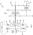
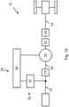
- FIG 1 An embodiment of the transmission system 10 is shown.
- Drive power is transmitted to an input shaft 12 from a drive, usually an internal combustion engine.
- the prime mover can also be a hydraulic motor.
- the Input shaft 12 is rotatably connected to a rotor of the input-side electric machine, as well as the inner rotor 52 of the magnetic-electric planetary gear stage 50.
- the input shaft is also used to supply drive power for a power take-off shaft or PTO and is designed as a continuous shaft.
- the input-side electric machine 16 is electrically connected to the output-side electric machine 18 and to a transmission system controller 40.
- the output-side electric machine 18 is in operative connection with the modulating ring 56 of the magnetic-electric planetary gear stage 50, which in turn interacts with the inner rotor 52.
- the input-side and output-side electric machine together with the magnetic-electric planetary gear represents the variable transmission branch 24, and together with the input shaft the power-split transmission section 20.
- the mechanical transmission branch 24 is formed from the continuous input shaft 12.
- the modulating ring 56 is connected by means of a hollow shaft which surrounds the input shaft 12 .
- the hollow shaft is designed to be connected to the manual transmission 30 and by means of a power-shift clutch to a first gear pair F1 or to a further gear pair F2.
- the gear pairs F1 and F2 form the manual transmission 30 of the transmission system 10.
- the gear pairs F1 and F2 transmit the drive power to the output shaft 14, which in turn is used for transmission to the output.
- the second pair of gears F2 is not connected in a rotationally fixed manner to the output shaft 14, but is connected in a rotationally fixed manner to the latter via a coupling element by shifting.
- the first pair of gears F1 is non-rotatably connected to the output shaft 14, so that when the coupling element is freewheeling and the power shift clutch in the manual transmission is in a corresponding position, the drive torque is transmitted via the first pair of gears F1.
- Another pair of gears R for a reverse gear can be connected to the second pair of gears F2.
- the direction of rotation is reversed by means of an additional intermediate shaft between the input shaft 12 and the output shaft 14 .
- the gear wheel pair R On the output shaft, the gear wheel pair R is not connected in a rotationally fixed manner to the output shaft 14 and is shifted by means of the coupling element.
- the first gear pair F1, the second gear pair F2 or the reverse gear R are connected to the output.
- the drive power is divided in the power-split transmission section 20 means Control of the input-side electric machine 16 and a corresponding proportion converted into electrical power. The remaining mechanical part is passed through the input shaft 12 or remains in it.
- the electric power is controlled by the transmission system controller 40 and the output electric machine 18 is controlled and supplied with electric power. Controlling the current and voltage influences the torque and speed that is generated, so that the action of the modulating ring 56 and the inner rotor 52 results in an outgoing speed and an outgoing torque at the modulating ring 56 .
- the portion of remaining power in the input shaft is sent to the PTO, while the remaining portion is sent to the gearbox.
- one of the power shift clutches for F1 or F2 is closed, while the other power shift clutch in each case is opened.
- the coupling element on the output shaft 14 is switched over.
- the transmission system would change the moment of inertia due to the change in the power path and the resulting speed and torque, so that this change could be felt by the operator.
- the vehicle experiences a change in speed.
- the invention provides that the electrical drive power is adjusted at the same time as the shifting processes in the manual transmission 30, such that the transmission system controller 40 changes the excitation frequency of the windings in the outer stator 54 of the magnetic-electric planetary gear stage 54.
- the change itself causes no torque or speed change, so the change in inertia of the transmission system is kept very small. With this reduction, the vehicle does not undergo any perceptible change in speed.
- the input torque is applied simultaneously to the first electric machine 16 and to the inner rotor 52 via the input shaft 12 .
- the first electrical machine 16 converts this into electrical power, with the actuation taking place via the transmission system controller 40 .
- the electrical power is delivered via the second electric machine 18 with an outer stator 54 . By changing the excitation frequency, different speeds can be set in the magnetic-electric planetary gear stage.
- the power applied to the inner rotor 52, as the power applied to the outer stator 54 also causes the power to be applied to the modulating ring 56.
- the power is delivered to the transmission 30 via the modulating ring 56 and is conducted via the gear pairs F1, F2 or R by switching the respective clutches.
- the transmission system is capable of compensating for the impulse that occurs at the time of shifting due to a simultaneous change in the speed in the magnetic-electric planetary gear stage 50 and maintaining harmonious, jerk-free operation during shifting operations.
- the transmission system 10 can enable purely electric starting, since there is no mechanical connection between the drive and the output.
- a purely electrical starting can be implemented. This is done in the serial electric launch module 70. This is particularly beneficial with a heavy trailer load, which typically requires a large reduction gear to launch at low vehicle speeds.
- figure 2 describes a known power-split transmission system from the prior art, which has a variable branch with two outputs 1 and 2.
- the drive power is routed via the input shaft 112 to a first gear wheel G1 and routed to a first electric machine 116 and to a reverse gear 132 by means of the other gear wheels G2 and G zw or G3.
- variable power component is transmitted electrically to a second electric machine 118 and reunited with the mechanical power by means of a magnetic electric planetary gear stage 150 .
- the transmission system according to the prior art has two outputs OUT1 and OUT2, which, depending on the application, can be connected to the output by means of a power shift clutch.
- the drive power is then passed through a manual transmission 130, different translations being set by means of two clutches.
- the solution using two outputs after the power-split transmission allows the outputs to be switched at the same time as the power-shift clutches in the manual transmission 130 are switched. This, together with the change in speed and torque in the manual transmission 130, changes the speed and torque at the output of the power-split transmission section 120. This leads to an equalization of impulse at the switching time.
- the structure of the transmission system 100 is significantly more complex. Two outputs of the power-split transmission section must be reserved, together with two power shift clutches and two additional planetary stages.
- the control of the transmission system 130 is designed in such a way that it is only possible to switch between two different speed ratios. Overall, this leads to greater manufacturing complexity, a higher number of components and increased weight.
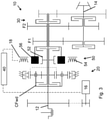
- FIG 3 shows another embodiment of the transmission system according to the invention.
- the first electric machine 16 is driven via a shaft of a gear wheel which is supplied with the input torque at a constant transmission ratio.
- the drive power is introduced into the planet carrier of an epicyclic gear. This has an outer ring that can be blocked and has a power-shift clutch with which the planet carrier can be coupled to the sun.
- the output of the planetary gear is also via the sun, so that the drive power continues to be parallel via the input shaft 12 and the sun shaft.
- variable power component is introduced by means of the second electric machine 18 and a further sun gear of the magnetic-electric planetary gear stage 50, with the modulatable ring 56 being able to be coupled to the inner rotor in the function as a sun gear by means of a further load-shifting clutch.
- the variable power component is regulated between the first and second electric machines 16 and 18 .
- a subsequent gearbox 30 with another parallel shaft to the output follows.
- the gearbox has two gear wheel pairs F1 and F2 which can be coupled to the sun shaft by means of power shift clutches.
- the input shaft 12 is used to supply the PTO or PTO.
- another lower gear is provided as a slow gear or creep.
- the reverse gear in the transmission system 10 is provided by closing or opening the powershift clutch C Fwd , as a result of which the direction of rotation is reversed at the sun gear or at the sun shaft of the planetary gear.
- Figures 4 to 12 show a schematic structure of further embodiments of the transmission system 10 according to the invention.
- the individual components correspond to those of the training figures 1 and 3 .
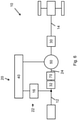
- figure 4 shows a transmission system 10 according to the invention figure 1 , whereby the version does not have a separate reverse gear.
- the driving torque is divided between the mechanical transmission branch 24 and the variable transmission branch 22, which consists of the first and second electric machines 16 and 18.
- the second electric machine 18 is part of the magnetic-electric planetary gear stage 50.
- the manual transmission 30 is formed following in the power path. Starting from this, the drive power is directed to one or more axles of the vehicle and finally to the output.
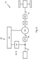
- figure 5 shows an embodiment in which the transmission system 10 additionally has a reverse gear 32, which is provided in the power path between the manual transmission 30 and the vehicle axles.
- figure 6 shows an embodiment in which the reverse gear 32 is formed in the area between the first electric machine 16 and the magnetic-electric planetary gear stage 50 in the power path.
- a module for serial electrical starting 70 is provided in the power path, which enables the vehicle to be started without direct mechanical coupling of the drive to the output.
- figure 7 describes an embodiment in which the reverse gear 32 is formed in the power path between the magnetic-electric planetary gear stage 50 and the manual transmission 30 .
- figure 8 shows an embodiment in which the module for serial electric starting 70 is provided in the power path between the first electric machine 16 and the magnetic-electric planetary gear stage 50 . Furthermore, the reverse gear 32 is formed between the transmission 30 and the vehicle axles.
- figure 9 describes an embodiment with the module for serial electric start-up 70 according to FIG figure 8 , with no reverse gear. This is carried out via the magnetic-electric epicyclic gear stage 50, so that a reversal of the direction of rotation is present at the output of the magnetic-electric epicyclic gear stage 50.
- figure 10 shows a further embodiment, the module for serial electric starting 70 being formed in the power path between the first electric machine 16 and the magnetic-electric planetary gear stage 50 .
- the reverse gear 32 is provided in the power path between the magnetic-electric planetary gear stage 50 and the manual transmission 30 .
- figure 11 shows an embodiment in which the reverse gear 32 within the Manual transmission 30 is formed.
- figure 12 shows an embodiment with the reverse gear 32 in the power path between the first electric machine 16 and the magnetic-electric planetary gear stage 50.
Landscapes
- Engineering & Computer Science (AREA)
- Mechanical Engineering (AREA)
- Chemical & Material Sciences (AREA)
- Combustion & Propulsion (AREA)
- Transportation (AREA)
- Power Engineering (AREA)
- General Engineering & Computer Science (AREA)
- Structure Of Transmissions (AREA)
- Dynamo-Electric Clutches, Dynamo-Electric Brakes (AREA)
- Arrangement Of Transmissions (AREA)
- Connection Of Motors, Electrical Generators, Mechanical Devices, And The Like (AREA)
Priority Applications (1)
| Application Number | Priority Date | Filing Date | Title |
|---|---|---|---|
| EP23185453.0A EP4246014A3 (fr) | 2020-07-29 | 2021-07-12 | Système de transmission |
Applications Claiming Priority (1)
| Application Number | Priority Date | Filing Date | Title |
|---|---|---|---|
| DE102020119984.8A DE102020119984A1 (de) | 2020-07-29 | 2020-07-29 | Getriebesystem |
Related Child Applications (2)
| Application Number | Title | Priority Date | Filing Date |
|---|---|---|---|
| EP23185453.0A Division EP4246014A3 (fr) | 2020-07-29 | 2021-07-12 | Système de transmission |
| EP23185453.0A Division-Into EP4246014A3 (fr) | 2020-07-29 | 2021-07-12 | Système de transmission |
Publications (2)
| Publication Number | Publication Date |
|---|---|
| EP3945665A1 true EP3945665A1 (fr) | 2022-02-02 |
| EP3945665B1 EP3945665B1 (fr) | 2025-03-05 |
Family
ID=76890813
Family Applications (2)
| Application Number | Title | Priority Date | Filing Date |
|---|---|---|---|
| EP21184936.9A Active EP3945665B1 (fr) | 2020-07-29 | 2021-07-12 | Système de boîte de vitesses |
| EP23185453.0A Withdrawn EP4246014A3 (fr) | 2020-07-29 | 2021-07-12 | Système de transmission |
Family Applications After (1)
| Application Number | Title | Priority Date | Filing Date |
|---|---|---|---|
| EP23185453.0A Withdrawn EP4246014A3 (fr) | 2020-07-29 | 2021-07-12 | Système de transmission |
Country Status (3)
| Country | Link |
|---|---|
| US (1) | US11691497B2 (fr) |
| EP (2) | EP3945665B1 (fr) |
| DE (1) | DE102020119984A1 (fr) |
Cited By (4)
| Publication number | Priority date | Publication date | Assignee | Title |
|---|---|---|---|---|
| DE102023102489A1 (de) | 2023-02-01 | 2024-08-01 | Deere & Company | Antriebsstrang und Fahrzeug |
| EP4589171A1 (fr) * | 2024-01-17 | 2025-07-23 | Deere & Company | Ensemble de transmission et véhicule de traction agricole |
| US12385556B2 (en) | 2023-05-11 | 2025-08-12 | Deere & Company | Transmission arrangement and agricultural towing vehicle |
| EP4678941A1 (fr) | 2024-07-12 | 2026-01-14 | Deere & Company | Ensemble de transmission et véhicule de traction agricole |
Families Citing this family (3)
| Publication number | Priority date | Publication date | Assignee | Title |
|---|---|---|---|---|
| US12115858B2 (en) | 2022-07-05 | 2024-10-15 | Deere & Company | Adjustable drop transmission assembly for a work vehicle |
| US12502945B2 (en) | 2022-07-19 | 2025-12-23 | Deere & Company | Hybrid or electric-only transaxle arrangement for work vehicle |
| EP4678444A1 (fr) | 2024-07-12 | 2026-01-14 | Deere & Company | Agencement d'entraînement, essieu et machine de travail |
Citations (5)
| Publication number | Priority date | Publication date | Assignee | Title |
|---|---|---|---|---|
| US20090247341A1 (en) * | 2006-10-25 | 2009-10-01 | Honda Motor Co., Ltd. | Power plant |
| EP2179879A1 (fr) * | 2007-08-27 | 2010-04-28 | Kabushiki Kaisha Toyota Chuo Kenkyusho | Dispositif de transmission de puissance |
| DE102010022527A1 (de) * | 2009-06-03 | 2010-12-16 | Kabushiki Kaisha Toyota Chuo Kenkyusho | Leistungsübertragungsvorrichtung |
| WO2013121266A1 (fr) * | 2012-02-14 | 2013-08-22 | Toyota Jidosha Kabushiki Kaisha | Unité d'entraînement pour véhicule |
| CN108340766A (zh) * | 2018-01-03 | 2018-07-31 | 北京理工大学 | 混合动力系统、车辆及其控制方法 |
Family Cites Families (5)
| Publication number | Priority date | Publication date | Assignee | Title |
|---|---|---|---|---|
| JP2016049932A (ja) * | 2014-09-02 | 2016-04-11 | 株式会社デンソー | 統合二軸回転機システム |
| DE102017208985A1 (de) | 2017-05-29 | 2018-11-29 | Deere & Company | Magnetisches Umlaufgetriebe mit variierbarem Drehmoment |
| DE102017219758A1 (de) * | 2017-11-07 | 2019-05-09 | Deere & Company | Differenzialanordnung |
| DE102018200953A1 (de) * | 2018-01-22 | 2019-07-25 | Deere & Company | Fahrzeug mit einer Anordnung zur dynamischen Anpassung des Vorlaufs |
| DE102018204405A1 (de) | 2018-03-22 | 2019-09-26 | Deere & Company | Zapfwellengetriebe |
-
2020
- 2020-07-29 DE DE102020119984.8A patent/DE102020119984A1/de active Pending
-
2021
- 2021-07-06 US US17/305,350 patent/US11691497B2/en active Active
- 2021-07-12 EP EP21184936.9A patent/EP3945665B1/fr active Active
- 2021-07-12 EP EP23185453.0A patent/EP4246014A3/fr not_active Withdrawn
Patent Citations (5)
| Publication number | Priority date | Publication date | Assignee | Title |
|---|---|---|---|---|
| US20090247341A1 (en) * | 2006-10-25 | 2009-10-01 | Honda Motor Co., Ltd. | Power plant |
| EP2179879A1 (fr) * | 2007-08-27 | 2010-04-28 | Kabushiki Kaisha Toyota Chuo Kenkyusho | Dispositif de transmission de puissance |
| DE102010022527A1 (de) * | 2009-06-03 | 2010-12-16 | Kabushiki Kaisha Toyota Chuo Kenkyusho | Leistungsübertragungsvorrichtung |
| WO2013121266A1 (fr) * | 2012-02-14 | 2013-08-22 | Toyota Jidosha Kabushiki Kaisha | Unité d'entraînement pour véhicule |
| CN108340766A (zh) * | 2018-01-03 | 2018-07-31 | 北京理工大学 | 混合动力系统、车辆及其控制方法 |
Cited By (5)
| Publication number | Priority date | Publication date | Assignee | Title |
|---|---|---|---|---|
| DE102023102489A1 (de) | 2023-02-01 | 2024-08-01 | Deere & Company | Antriebsstrang und Fahrzeug |
| EP4410576A1 (fr) | 2023-02-01 | 2024-08-07 | Deere & Company | Chaîne cinématique et véhicule |
| US12385556B2 (en) | 2023-05-11 | 2025-08-12 | Deere & Company | Transmission arrangement and agricultural towing vehicle |
| EP4589171A1 (fr) * | 2024-01-17 | 2025-07-23 | Deere & Company | Ensemble de transmission et véhicule de traction agricole |
| EP4678941A1 (fr) | 2024-07-12 | 2026-01-14 | Deere & Company | Ensemble de transmission et véhicule de traction agricole |
Also Published As
| Publication number | Publication date |
|---|---|
| EP4246014A2 (fr) | 2023-09-20 |
| US20220032763A1 (en) | 2022-02-03 |
| EP4246014A3 (fr) | 2023-11-08 |
| DE102020119984A1 (de) | 2022-02-03 |
| EP3945665B1 (fr) | 2025-03-05 |
| US11691497B2 (en) | 2023-07-04 |
Similar Documents
| Publication | Publication Date | Title |
|---|---|---|
| EP3945665B1 (fr) | Système de boîte de vitesses | |
| EP3707411B1 (fr) | Transmission à variation continue à dérivation de puissance présentant au moins quatre plages de marche | |
| DE102016204727A1 (de) | Stufenlos leistungsverzweigtes Getriebe mit mindestens einem Fahrbereich | |
| WO2012055527A1 (fr) | Unité de transmission et unité électrique complémentaire | |
| DE102018213893A1 (de) | Kraftfahrzeuggetriebe, insbesondere für ein landwirtschaftliches oder kommunales Nutzfahrzeug, sowie Kraftfahrzeugantriebsstrang | |
| DE102017206413A1 (de) | Leistungsverzweigtes Stufenlosgetriebesystem | |
| DE102022204738B4 (de) | Antriebsvorrichtung für eine Arbeitsmaschine | |
| DE102018213891B4 (de) | Kraftfahrzeuggetriebe, insbesondere für ein landwirtschaftliches oder kommunales Nutzfahrzeug, sowie Kraftfahrzeugantriebsstrang | |
| DE102019200966B4 (de) | Leistungsverzweigtes Kraftfahrzeuggetriebe | |
| DE102018213876A1 (de) | Kraftfahrzeuggetriebe, insbesondere für ein landwirtschaftliches oder kommunales Nutzfahrzeug, sowie Kraftfahrzeugantriebsstrang | |
| DE102018213890A1 (de) | Kraftfahrzeuggetriebe, insbesondere für ein landwirtschaftliches oder kommunales Nutzfahrzeug, sowie Kraftfahrzeugantriebsstrang | |
| DE102018213888A1 (de) | Kraftfahrzeuggetriebe, insbesondere für ein landwirtschaftliches oder kommunales Nutzfahrzeug, sowie Kraftfahrzeugantriebsstrang | |
| DE102022200713A1 (de) | Antriebsstrang für eine Arbeitsmaschine | |
| DE102018213884B4 (de) | Kraftfahrzeuggetriebe, insbesondere für ein landwirtschaftliches oder kommunales Nutzfahrzeug, sowie Kraftfahrzeugantriebsstrang | |
| DE102016206204B4 (de) | Leistungsverzweigter Antriebsstrang für eine Arbeitsmaschine | |
| DE102022212547B4 (de) | Leistungsstrang für eine Arbeitsmaschine und Arbeitsmaschine | |
| DE102018213881A1 (de) | Kraftfahrzeuggetriebe, insbesondere für ein landwirtschaftliches oder kommunales Nutzfahrzeug, sowie Kraftfahrzeugantriebsstrang | |
| DE102018213883A1 (de) | Kraftfahrzeuggetriebe, insbesondere für ein landwirtschaftliches oder kommunales Nutzfahrzeug, sowie Kraftfahrzeugantriebsstrang | |
| DE102018213879A1 (de) | Kraftfahrzeuggetriebe, insbesondere für ein landwirtschaftliches oder kommunales Nutzfahrzeug, sowie Kraftfahrzeugantriebsstrang | |
| DE102018213875A1 (de) | Kraftfahrzeuggetriebe, insbesondere für ein landwirtschaftliches oder kommunales Nutzfahrzeug, sowie Kraftfahrzeugantriebsstrang | |
| DE102018213892B4 (de) | Kraftfahrzeuggetriebe, insbesondere für ein landwirtschaftliches oder kommunales Nutzfahrzeug, sowie Kraftfahrzeugantriebsstrang | |
| DE102018213887B4 (de) | Kraftfahrzeuggetriebe, insbesondere für ein landwirtschaftliches oder kommunales Nutzfahrzeug, sowie Kraftfahrzeugantriebsstrang | |
| DE102019200970B4 (de) | Kraftfahrzeuggetriebe, insbesondere für ein landwirtschaftliches oder kommunales Nutzfahrzeug, sowie Kraftfahrzeugantriebsstrang | |
| DE102018213885B4 (de) | Kraftfahrzeuggetriebe, insbesondere für ein landwirtschaftliches oder kommunales Nutzfahrzeug, sowie Kraftfahrzeugantriebsstrang | |
| DE102017219105B4 (de) | Leistungsverzweigte stufenlose Getriebevorrichtung |
Legal Events
| Date | Code | Title | Description |
|---|---|---|---|
| PUAI | Public reference made under article 153(3) epc to a published international application that has entered the european phase |
Free format text: ORIGINAL CODE: 0009012 |
|
| STAA | Information on the status of an ep patent application or granted ep patent |
Free format text: STATUS: THE APPLICATION HAS BEEN PUBLISHED |
|
| AK | Designated contracting states |
Kind code of ref document: A1 Designated state(s): AL AT BE BG CH CY CZ DE DK EE ES FI FR GB GR HR HU IE IS IT LI LT LU LV MC MK MT NL NO PL PT RO RS SE SI SK SM TR |
|
| STAA | Information on the status of an ep patent application or granted ep patent |
Free format text: STATUS: REQUEST FOR EXAMINATION WAS MADE |
|
| 17P | Request for examination filed |
Effective date: 20220802 |
|
| RBV | Designated contracting states (corrected) |
Designated state(s): AL AT BE BG CH CY CZ DE DK EE ES FI FR GB GR HR HU IE IS IT LI LT LU LV MC MK MT NL NO PL PT RO RS SE SI SK SM TR |
|
| STAA | Information on the status of an ep patent application or granted ep patent |
Free format text: STATUS: EXAMINATION IS IN PROGRESS |
|
| 17Q | First examination report despatched |
Effective date: 20230508 |
|
| GRAP | Despatch of communication of intention to grant a patent |
Free format text: ORIGINAL CODE: EPIDOSNIGR1 |
|
| STAA | Information on the status of an ep patent application or granted ep patent |
Free format text: STATUS: GRANT OF PATENT IS INTENDED |
|
| INTG | Intention to grant announced |
Effective date: 20241017 |
|
| GRAS | Grant fee paid |
Free format text: ORIGINAL CODE: EPIDOSNIGR3 |
|
| GRAA | (expected) grant |
Free format text: ORIGINAL CODE: 0009210 |
|
| STAA | Information on the status of an ep patent application or granted ep patent |
Free format text: STATUS: THE PATENT HAS BEEN GRANTED |
|
| AK | Designated contracting states |
Kind code of ref document: B1 Designated state(s): AL AT BE BG CH CY CZ DE DK EE ES FI FR GB GR HR HU IE IS IT LI LT LU LV MC MK MT NL NO PL PT RO RS SE SI SK SM TR |
|
| REG | Reference to a national code |
Ref country code: GB Ref legal event code: FG4D Free format text: NOT ENGLISH |
|
| REG | Reference to a national code |
Ref country code: CH Ref legal event code: EP |
|
| REG | Reference to a national code |
Ref country code: DE Ref legal event code: R096 Ref document number: 502021006837 Country of ref document: DE |
|
| REG | Reference to a national code |
Ref country code: IE Ref legal event code: FG4D Free format text: LANGUAGE OF EP DOCUMENT: GERMAN |
|
| PG25 | Lapsed in a contracting state [announced via postgrant information from national office to epo] |
Ref country code: RS Free format text: LAPSE BECAUSE OF FAILURE TO SUBMIT A TRANSLATION OF THE DESCRIPTION OR TO PAY THE FEE WITHIN THE PRESCRIBED TIME-LIMIT Effective date: 20250605 |
|
| PG25 | Lapsed in a contracting state [announced via postgrant information from national office to epo] |
Ref country code: FI Free format text: LAPSE BECAUSE OF FAILURE TO SUBMIT A TRANSLATION OF THE DESCRIPTION OR TO PAY THE FEE WITHIN THE PRESCRIBED TIME-LIMIT Effective date: 20250305 |
|
| REG | Reference to a national code |
Ref country code: NL Ref legal event code: MP Effective date: 20250305 |
|
| PG25 | Lapsed in a contracting state [announced via postgrant information from national office to epo] |
Ref country code: ES Free format text: LAPSE BECAUSE OF FAILURE TO SUBMIT A TRANSLATION OF THE DESCRIPTION OR TO PAY THE FEE WITHIN THE PRESCRIBED TIME-LIMIT Effective date: 20250305 |
|
| REG | Reference to a national code |
Ref country code: LT Ref legal event code: MG9D |
|
| PG25 | Lapsed in a contracting state [announced via postgrant information from national office to epo] |
Ref country code: NO Free format text: LAPSE BECAUSE OF FAILURE TO SUBMIT A TRANSLATION OF THE DESCRIPTION OR TO PAY THE FEE WITHIN THE PRESCRIBED TIME-LIMIT Effective date: 20250605 |
|
| PG25 | Lapsed in a contracting state [announced via postgrant information from national office to epo] |
Ref country code: HR Free format text: LAPSE BECAUSE OF FAILURE TO SUBMIT A TRANSLATION OF THE DESCRIPTION OR TO PAY THE FEE WITHIN THE PRESCRIBED TIME-LIMIT Effective date: 20250305 |
|
| PG25 | Lapsed in a contracting state [announced via postgrant information from national office to epo] |
Ref country code: LV Free format text: LAPSE BECAUSE OF FAILURE TO SUBMIT A TRANSLATION OF THE DESCRIPTION OR TO PAY THE FEE WITHIN THE PRESCRIBED TIME-LIMIT Effective date: 20250305 |
|
| PG25 | Lapsed in a contracting state [announced via postgrant information from national office to epo] |
Ref country code: GR Free format text: LAPSE BECAUSE OF FAILURE TO SUBMIT A TRANSLATION OF THE DESCRIPTION OR TO PAY THE FEE WITHIN THE PRESCRIBED TIME-LIMIT Effective date: 20250606 Ref country code: BG Free format text: LAPSE BECAUSE OF FAILURE TO SUBMIT A TRANSLATION OF THE DESCRIPTION OR TO PAY THE FEE WITHIN THE PRESCRIBED TIME-LIMIT Effective date: 20250305 |
|
| PG25 | Lapsed in a contracting state [announced via postgrant information from national office to epo] |
Ref country code: NL Free format text: LAPSE BECAUSE OF FAILURE TO SUBMIT A TRANSLATION OF THE DESCRIPTION OR TO PAY THE FEE WITHIN THE PRESCRIBED TIME-LIMIT Effective date: 20250305 |
|
| PG25 | Lapsed in a contracting state [announced via postgrant information from national office to epo] |
Ref country code: SE Free format text: LAPSE BECAUSE OF FAILURE TO SUBMIT A TRANSLATION OF THE DESCRIPTION OR TO PAY THE FEE WITHIN THE PRESCRIBED TIME-LIMIT Effective date: 20250305 |
|
| PG25 | Lapsed in a contracting state [announced via postgrant information from national office to epo] |
Ref country code: SM Free format text: LAPSE BECAUSE OF FAILURE TO SUBMIT A TRANSLATION OF THE DESCRIPTION OR TO PAY THE FEE WITHIN THE PRESCRIBED TIME-LIMIT Effective date: 20250305 |
|
| PG25 | Lapsed in a contracting state [announced via postgrant information from national office to epo] |
Ref country code: PT Free format text: LAPSE BECAUSE OF FAILURE TO SUBMIT A TRANSLATION OF THE DESCRIPTION OR TO PAY THE FEE WITHIN THE PRESCRIBED TIME-LIMIT Effective date: 20250707 |
|
| PGFP | Annual fee paid to national office [announced via postgrant information from national office to epo] |
Ref country code: DE Payment date: 20250620 Year of fee payment: 5 |
|
| PG25 | Lapsed in a contracting state [announced via postgrant information from national office to epo] |
Ref country code: IT Free format text: LAPSE BECAUSE OF FAILURE TO SUBMIT A TRANSLATION OF THE DESCRIPTION OR TO PAY THE FEE WITHIN THE PRESCRIBED TIME-LIMIT Effective date: 20250305 Ref country code: PL Free format text: LAPSE BECAUSE OF FAILURE TO SUBMIT A TRANSLATION OF THE DESCRIPTION OR TO PAY THE FEE WITHIN THE PRESCRIBED TIME-LIMIT Effective date: 20250305 |
|
| PGFP | Annual fee paid to national office [announced via postgrant information from national office to epo] |
Ref country code: AT Payment date: 20251020 Year of fee payment: 5 Ref country code: FR Payment date: 20250725 Year of fee payment: 5 |
|
| PG25 | Lapsed in a contracting state [announced via postgrant information from national office to epo] |
Ref country code: CZ Free format text: LAPSE BECAUSE OF FAILURE TO SUBMIT A TRANSLATION OF THE DESCRIPTION OR TO PAY THE FEE WITHIN THE PRESCRIBED TIME-LIMIT Effective date: 20250305 Ref country code: EE Free format text: LAPSE BECAUSE OF FAILURE TO SUBMIT A TRANSLATION OF THE DESCRIPTION OR TO PAY THE FEE WITHIN THE PRESCRIBED TIME-LIMIT Effective date: 20250305 |
|
| PG25 | Lapsed in a contracting state [announced via postgrant information from national office to epo] |
Ref country code: RO Free format text: LAPSE BECAUSE OF FAILURE TO SUBMIT A TRANSLATION OF THE DESCRIPTION OR TO PAY THE FEE WITHIN THE PRESCRIBED TIME-LIMIT Effective date: 20250305 |
|
| PG25 | Lapsed in a contracting state [announced via postgrant information from national office to epo] |
Ref country code: SK Free format text: LAPSE BECAUSE OF FAILURE TO SUBMIT A TRANSLATION OF THE DESCRIPTION OR TO PAY THE FEE WITHIN THE PRESCRIBED TIME-LIMIT Effective date: 20250305 |
|
| PG25 | Lapsed in a contracting state [announced via postgrant information from national office to epo] |
Ref country code: IS Free format text: LAPSE BECAUSE OF FAILURE TO SUBMIT A TRANSLATION OF THE DESCRIPTION OR TO PAY THE FEE WITHIN THE PRESCRIBED TIME-LIMIT Effective date: 20250705 |
|
| REG | Reference to a national code |
Ref country code: CH Ref legal event code: W10 Free format text: ST27 STATUS EVENT CODE: U-0-0-W10-W00 (AS PROVIDED BY THE NATIONAL OFFICE) Effective date: 20251119 |
|
| REG | Reference to a national code |
Ref country code: DE Ref legal event code: R097 Ref document number: 502021006837 Country of ref document: DE |
|
| RAP4 | Party data changed (patent owner data changed or rights of a patent transferred) |
Owner name: DEERE & COMPANY |
|
| PLBE | No opposition filed within time limit |
Free format text: ORIGINAL CODE: 0009261 |
|
| STAA | Information on the status of an ep patent application or granted ep patent |
Free format text: STATUS: NO OPPOSITION FILED WITHIN TIME LIMIT |
|
| PG25 | Lapsed in a contracting state [announced via postgrant information from national office to epo] |
Ref country code: DK Free format text: LAPSE BECAUSE OF FAILURE TO SUBMIT A TRANSLATION OF THE DESCRIPTION OR TO PAY THE FEE WITHIN THE PRESCRIBED TIME-LIMIT Effective date: 20250305 |
|
| REG | Reference to a national code |
Ref country code: CH Ref legal event code: L10 Free format text: ST27 STATUS EVENT CODE: U-0-0-L10-L00 (AS PROVIDED BY THE NATIONAL OFFICE) Effective date: 20260114 |
|
| 26N | No opposition filed |
Effective date: 20251208 |
|
| REG | Reference to a national code |
Ref country code: CH Ref legal event code: H13 Free format text: ST27 STATUS EVENT CODE: U-0-0-H10-H13 (AS PROVIDED BY THE NATIONAL OFFICE) Effective date: 20260224 |
|
| PG25 | Lapsed in a contracting state [announced via postgrant information from national office to epo] |
Ref country code: LU Free format text: LAPSE BECAUSE OF NON-PAYMENT OF DUE FEES Effective date: 20250712 |
|
| GBPC | Gb: european patent ceased through non-payment of renewal fee |
Effective date: 20250712 |
|
| REG | Reference to a national code |
Ref country code: BE Ref legal event code: MM Effective date: 20250731 |
|
| PG25 | Lapsed in a contracting state [announced via postgrant information from national office to epo] |
Ref country code: GB Free format text: LAPSE BECAUSE OF NON-PAYMENT OF DUE FEES Effective date: 20250712 |
|
| PG25 | Lapsed in a contracting state [announced via postgrant information from national office to epo] |
Ref country code: BE Free format text: LAPSE BECAUSE OF NON-PAYMENT OF DUE FEES Effective date: 20250731 |
|
| PG25 | Lapsed in a contracting state [announced via postgrant information from national office to epo] |
Ref country code: CH Free format text: LAPSE BECAUSE OF NON-PAYMENT OF DUE FEES Effective date: 20250731 |