EP3946889B1 - Outil de moulage par soufflage et procédé pour le traitement thermique d'une zone partielle d'une surface d'un récipient en plastique - Google Patents
Outil de moulage par soufflage et procédé pour le traitement thermique d'une zone partielle d'une surface d'un récipient en plastique Download PDFInfo
- Publication number
- EP3946889B1 EP3946889B1 EP20715052.5A EP20715052A EP3946889B1 EP 3946889 B1 EP3946889 B1 EP 3946889B1 EP 20715052 A EP20715052 A EP 20715052A EP 3946889 B1 EP3946889 B1 EP 3946889B1
- Authority
- EP
- European Patent Office
- Prior art keywords
- blow molding
- molding tool
- blow
- temperature
- temperature control
- Prior art date
- Legal status (The legal status is an assumption and is not a legal conclusion. Google has not performed a legal analysis and makes no representation as to the accuracy of the status listed.)
- Active
Links
Images

Classifications
-
- B—PERFORMING OPERATIONS; TRANSPORTING
- B29—WORKING OF PLASTICS; WORKING OF SUBSTANCES IN A PLASTIC STATE IN GENERAL
- B29C—SHAPING OR JOINING OF PLASTICS; SHAPING OF MATERIAL IN A PLASTIC STATE, NOT OTHERWISE PROVIDED FOR; AFTER-TREATMENT OF THE SHAPED PRODUCTS, e.g. REPAIRING
- B29C49/00—Blow-moulding, i.e. blowing a preform or parison to a desired shape within a mould; Apparatus therefor
- B29C49/42—Component parts, details or accessories; Auxiliary operations
- B29C49/48—Moulds
- B29C49/4823—Moulds with incorporated heating or cooling means
-
- B—PERFORMING OPERATIONS; TRANSPORTING
- B29—WORKING OF PLASTICS; WORKING OF SUBSTANCES IN A PLASTIC STATE IN GENERAL
- B29C—SHAPING OR JOINING OF PLASTICS; SHAPING OF MATERIAL IN A PLASTIC STATE, NOT OTHERWISE PROVIDED FOR; AFTER-TREATMENT OF THE SHAPED PRODUCTS, e.g. REPAIRING
- B29C49/00—Blow-moulding, i.e. blowing a preform or parison to a desired shape within a mould; Apparatus therefor
- B29C49/28—Blow-moulding apparatus
- B29C49/30—Blow-moulding apparatus having movable moulds or mould parts
-
- B—PERFORMING OPERATIONS; TRANSPORTING
- B29—WORKING OF PLASTICS; WORKING OF SUBSTANCES IN A PLASTIC STATE IN GENERAL
- B29C—SHAPING OR JOINING OF PLASTICS; SHAPING OF MATERIAL IN A PLASTIC STATE, NOT OTHERWISE PROVIDED FOR; AFTER-TREATMENT OF THE SHAPED PRODUCTS, e.g. REPAIRING
- B29C49/00—Blow-moulding, i.e. blowing a preform or parison to a desired shape within a mould; Apparatus therefor
- B29C49/42—Component parts, details or accessories; Auxiliary operations
- B29C49/64—Heating or cooling preforms, parisons or blown articles
-
- B—PERFORMING OPERATIONS; TRANSPORTING
- B29—WORKING OF PLASTICS; WORKING OF SUBSTANCES IN A PLASTIC STATE IN GENERAL
- B29C—SHAPING OR JOINING OF PLASTICS; SHAPING OF MATERIAL IN A PLASTIC STATE, NOT OTHERWISE PROVIDED FOR; AFTER-TREATMENT OF THE SHAPED PRODUCTS, e.g. REPAIRING
- B29C49/00—Blow-moulding, i.e. blowing a preform or parison to a desired shape within a mould; Apparatus therefor
- B29C49/42—Component parts, details or accessories; Auxiliary operations
- B29C49/48—Moulds
- B29C49/4823—Moulds with incorporated heating or cooling means
- B29C2049/4825—Moulds with incorporated heating or cooling means for cooling moulds or mould parts
-
- B—PERFORMING OPERATIONS; TRANSPORTING
- B29—WORKING OF PLASTICS; WORKING OF SUBSTANCES IN A PLASTIC STATE IN GENERAL
- B29C—SHAPING OR JOINING OF PLASTICS; SHAPING OF MATERIAL IN A PLASTIC STATE, NOT OTHERWISE PROVIDED FOR; AFTER-TREATMENT OF THE SHAPED PRODUCTS, e.g. REPAIRING
- B29C49/00—Blow-moulding, i.e. blowing a preform or parison to a desired shape within a mould; Apparatus therefor
- B29C49/42—Component parts, details or accessories; Auxiliary operations
- B29C49/48—Moulds
- B29C49/4823—Moulds with incorporated heating or cooling means
- B29C2049/4825—Moulds with incorporated heating or cooling means for cooling moulds or mould parts
- B29C2049/483—Moulds with incorporated heating or cooling means for cooling moulds or mould parts in different areas of the mould at different temperatures, e.g. neck, shoulder or bottom
-
- B—PERFORMING OPERATIONS; TRANSPORTING
- B29—WORKING OF PLASTICS; WORKING OF SUBSTANCES IN A PLASTIC STATE IN GENERAL
- B29C—SHAPING OR JOINING OF PLASTICS; SHAPING OF MATERIAL IN A PLASTIC STATE, NOT OTHERWISE PROVIDED FOR; AFTER-TREATMENT OF THE SHAPED PRODUCTS, e.g. REPAIRING
- B29C49/00—Blow-moulding, i.e. blowing a preform or parison to a desired shape within a mould; Apparatus therefor
- B29C49/42—Component parts, details or accessories; Auxiliary operations
- B29C49/48—Moulds
- B29C49/4823—Moulds with incorporated heating or cooling means
- B29C2049/4838—Moulds with incorporated heating or cooling means for heating moulds or mould parts
-
- B—PERFORMING OPERATIONS; TRANSPORTING
- B29—WORKING OF PLASTICS; WORKING OF SUBSTANCES IN A PLASTIC STATE IN GENERAL
- B29C—SHAPING OR JOINING OF PLASTICS; SHAPING OF MATERIAL IN A PLASTIC STATE, NOT OTHERWISE PROVIDED FOR; AFTER-TREATMENT OF THE SHAPED PRODUCTS, e.g. REPAIRING
- B29C49/00—Blow-moulding, i.e. blowing a preform or parison to a desired shape within a mould; Apparatus therefor
- B29C49/42—Component parts, details or accessories; Auxiliary operations
- B29C49/48—Moulds
- B29C49/4823—Moulds with incorporated heating or cooling means
- B29C2049/4838—Moulds with incorporated heating or cooling means for heating moulds or mould parts
- B29C2049/4846—Moulds with incorporated heating or cooling means for heating moulds or mould parts in different areas of the mould at different temperatures, e.g. neck, shoulder or bottom
-
- B—PERFORMING OPERATIONS; TRANSPORTING
- B29—WORKING OF PLASTICS; WORKING OF SUBSTANCES IN A PLASTIC STATE IN GENERAL
- B29C—SHAPING OR JOINING OF PLASTICS; SHAPING OF MATERIAL IN A PLASTIC STATE, NOT OTHERWISE PROVIDED FOR; AFTER-TREATMENT OF THE SHAPED PRODUCTS, e.g. REPAIRING
- B29C49/00—Blow-moulding, i.e. blowing a preform or parison to a desired shape within a mould; Apparatus therefor
- B29C49/42—Component parts, details or accessories; Auxiliary operations
- B29C49/48—Moulds
- B29C49/4823—Moulds with incorporated heating or cooling means
- B29C2049/4838—Moulds with incorporated heating or cooling means for heating moulds or mould parts
- B29C2049/4846—Moulds with incorporated heating or cooling means for heating moulds or mould parts in different areas of the mould at different temperatures, e.g. neck, shoulder or bottom
- B29C2049/4851—Side walls
-
- B—PERFORMING OPERATIONS; TRANSPORTING
- B29—WORKING OF PLASTICS; WORKING OF SUBSTANCES IN A PLASTIC STATE IN GENERAL
- B29C—SHAPING OR JOINING OF PLASTICS; SHAPING OF MATERIAL IN A PLASTIC STATE, NOT OTHERWISE PROVIDED FOR; AFTER-TREATMENT OF THE SHAPED PRODUCTS, e.g. REPAIRING
- B29C49/00—Blow-moulding, i.e. blowing a preform or parison to a desired shape within a mould; Apparatus therefor
- B29C49/42—Component parts, details or accessories; Auxiliary operations
- B29C49/48—Moulds
- B29C2049/4874—Moulds characterised by the material, e.g. having different thermal conductivities or hardness
-
- B—PERFORMING OPERATIONS; TRANSPORTING
- B29—WORKING OF PLASTICS; WORKING OF SUBSTANCES IN A PLASTIC STATE IN GENERAL
- B29C—SHAPING OR JOINING OF PLASTICS; SHAPING OF MATERIAL IN A PLASTIC STATE, NOT OTHERWISE PROVIDED FOR; AFTER-TREATMENT OF THE SHAPED PRODUCTS, e.g. REPAIRING
- B29C49/00—Blow-moulding, i.e. blowing a preform or parison to a desired shape within a mould; Apparatus therefor
- B29C49/42—Component parts, details or accessories; Auxiliary operations
- B29C49/48—Moulds
- B29C2049/4874—Moulds characterised by the material, e.g. having different thermal conductivities or hardness
- B29C2049/4876—Moulds characterised by the material, e.g. having different thermal conductivities or hardness one material being heat insulating material
-
- B—PERFORMING OPERATIONS; TRANSPORTING
- B29—WORKING OF PLASTICS; WORKING OF SUBSTANCES IN A PLASTIC STATE IN GENERAL
- B29C—SHAPING OR JOINING OF PLASTICS; SHAPING OF MATERIAL IN A PLASTIC STATE, NOT OTHERWISE PROVIDED FOR; AFTER-TREATMENT OF THE SHAPED PRODUCTS, e.g. REPAIRING
- B29C49/00—Blow-moulding, i.e. blowing a preform or parison to a desired shape within a mould; Apparatus therefor
- B29C49/42—Component parts, details or accessories; Auxiliary operations
- B29C49/48—Moulds
- B29C2049/4879—Moulds characterised by mould configurations
-
- B—PERFORMING OPERATIONS; TRANSPORTING
- B29—WORKING OF PLASTICS; WORKING OF SUBSTANCES IN A PLASTIC STATE IN GENERAL
- B29C—SHAPING OR JOINING OF PLASTICS; SHAPING OF MATERIAL IN A PLASTIC STATE, NOT OTHERWISE PROVIDED FOR; AFTER-TREATMENT OF THE SHAPED PRODUCTS, e.g. REPAIRING
- B29C2949/00—Indexing scheme relating to blow-moulding
- B29C2949/07—Preforms or parisons characterised by their configuration
- B29C2949/0715—Preforms or parisons characterised by their configuration the preform having one end closed
-
- B—PERFORMING OPERATIONS; TRANSPORTING
- B29—WORKING OF PLASTICS; WORKING OF SUBSTANCES IN A PLASTIC STATE IN GENERAL
- B29C—SHAPING OR JOINING OF PLASTICS; SHAPING OF MATERIAL IN A PLASTIC STATE, NOT OTHERWISE PROVIDED FOR; AFTER-TREATMENT OF THE SHAPED PRODUCTS, e.g. REPAIRING
- B29C49/00—Blow-moulding, i.e. blowing a preform or parison to a desired shape within a mould; Apparatus therefor
- B29C49/02—Combined blow-moulding and manufacture of the preform or the parison
- B29C49/04—Extrusion blow-moulding
-
- B—PERFORMING OPERATIONS; TRANSPORTING
- B29—WORKING OF PLASTICS; WORKING OF SUBSTANCES IN A PLASTIC STATE IN GENERAL
- B29C—SHAPING OR JOINING OF PLASTICS; SHAPING OF MATERIAL IN A PLASTIC STATE, NOT OTHERWISE PROVIDED FOR; AFTER-TREATMENT OF THE SHAPED PRODUCTS, e.g. REPAIRING
- B29C49/00—Blow-moulding, i.e. blowing a preform or parison to a desired shape within a mould; Apparatus therefor
- B29C49/02—Combined blow-moulding and manufacture of the preform or the parison
- B29C49/06—Injection blow-moulding
-
- B—PERFORMING OPERATIONS; TRANSPORTING
- B29—WORKING OF PLASTICS; WORKING OF SUBSTANCES IN A PLASTIC STATE IN GENERAL
- B29K—INDEXING SCHEME ASSOCIATED WITH SUBCLASSES B29B, B29C OR B29D, RELATING TO MOULDING MATERIALS OR TO MATERIALS FOR MOULDS, REINFORCEMENTS, FILLERS OR PREFORMED PARTS, e.g. INSERTS
- B29K2023/00—Use of polyalkenes or derivatives thereof as moulding material
-
- B—PERFORMING OPERATIONS; TRANSPORTING
- B29—WORKING OF PLASTICS; WORKING OF SUBSTANCES IN A PLASTIC STATE IN GENERAL
- B29K—INDEXING SCHEME ASSOCIATED WITH SUBCLASSES B29B, B29C OR B29D, RELATING TO MOULDING MATERIALS OR TO MATERIALS FOR MOULDS, REINFORCEMENTS, FILLERS OR PREFORMED PARTS, e.g. INSERTS
- B29K2023/00—Use of polyalkenes or derivatives thereof as moulding material
- B29K2023/10—Polymers of propylene
- B29K2023/12—PP, i.e. polypropylene
-
- B—PERFORMING OPERATIONS; TRANSPORTING
- B29—WORKING OF PLASTICS; WORKING OF SUBSTANCES IN A PLASTIC STATE IN GENERAL
- B29K—INDEXING SCHEME ASSOCIATED WITH SUBCLASSES B29B, B29C OR B29D, RELATING TO MOULDING MATERIALS OR TO MATERIALS FOR MOULDS, REINFORCEMENTS, FILLERS OR PREFORMED PARTS, e.g. INSERTS
- B29K2067/00—Use of polyesters or derivatives thereof, as moulding material
- B29K2067/003—PET, i.e. poylethylene terephthalate
-
- B—PERFORMING OPERATIONS; TRANSPORTING
- B29—WORKING OF PLASTICS; WORKING OF SUBSTANCES IN A PLASTIC STATE IN GENERAL
- B29K—INDEXING SCHEME ASSOCIATED WITH SUBCLASSES B29B, B29C OR B29D, RELATING TO MOULDING MATERIALS OR TO MATERIALS FOR MOULDS, REINFORCEMENTS, FILLERS OR PREFORMED PARTS, e.g. INSERTS
- B29K2871/00—Use of polyethers, e.g. PEEK, i.e. polyether-etherketone or PEK, i.e. polyetherketone or derivatives thereof, as mould material
-
- B—PERFORMING OPERATIONS; TRANSPORTING
- B29—WORKING OF PLASTICS; WORKING OF SUBSTANCES IN A PLASTIC STATE IN GENERAL
- B29K—INDEXING SCHEME ASSOCIATED WITH SUBCLASSES B29B, B29C OR B29D, RELATING TO MOULDING MATERIALS OR TO MATERIALS FOR MOULDS, REINFORCEMENTS, FILLERS OR PREFORMED PARTS, e.g. INSERTS
- B29K2905/00—Use of metals, their alloys or their compounds, as mould material
- B29K2905/02—Aluminium
-
- B—PERFORMING OPERATIONS; TRANSPORTING
- B29—WORKING OF PLASTICS; WORKING OF SUBSTANCES IN A PLASTIC STATE IN GENERAL
- B29K—INDEXING SCHEME ASSOCIATED WITH SUBCLASSES B29B, B29C OR B29D, RELATING TO MOULDING MATERIALS OR TO MATERIALS FOR MOULDS, REINFORCEMENTS, FILLERS OR PREFORMED PARTS, e.g. INSERTS
- B29K2905/00—Use of metals, their alloys or their compounds, as mould material
- B29K2905/08—Transition metals
- B29K2905/12—Iron
-
- B—PERFORMING OPERATIONS; TRANSPORTING
- B29—WORKING OF PLASTICS; WORKING OF SUBSTANCES IN A PLASTIC STATE IN GENERAL
- B29K—INDEXING SCHEME ASSOCIATED WITH SUBCLASSES B29B, B29C OR B29D, RELATING TO MOULDING MATERIALS OR TO MATERIALS FOR MOULDS, REINFORCEMENTS, FILLERS OR PREFORMED PARTS, e.g. INSERTS
- B29K2995/00—Properties of moulding materials, reinforcements, fillers, preformed parts or moulds
- B29K2995/0012—Properties of moulding materials, reinforcements, fillers, preformed parts or moulds having particular thermal properties
- B29K2995/0015—Insulating
-
- B—PERFORMING OPERATIONS; TRANSPORTING
- B29—WORKING OF PLASTICS; WORKING OF SUBSTANCES IN A PLASTIC STATE IN GENERAL
- B29K—INDEXING SCHEME ASSOCIATED WITH SUBCLASSES B29B, B29C OR B29D, RELATING TO MOULDING MATERIALS OR TO MATERIALS FOR MOULDS, REINFORCEMENTS, FILLERS OR PREFORMED PARTS, e.g. INSERTS
- B29K2995/00—Properties of moulding materials, reinforcements, fillers, preformed parts or moulds
- B29K2995/0018—Properties of moulding materials, reinforcements, fillers, preformed parts or moulds having particular optical properties, e.g. fluorescent or phosphorescent
- B29K2995/003—Reflective
-
- B—PERFORMING OPERATIONS; TRANSPORTING
- B29—WORKING OF PLASTICS; WORKING OF SUBSTANCES IN A PLASTIC STATE IN GENERAL
- B29L—INDEXING SCHEME ASSOCIATED WITH SUBCLASS B29C, RELATING TO PARTICULAR ARTICLES
- B29L2031/00—Other particular articles
- B29L2031/712—Containers; Packaging elements or accessories, Packages
-
- B—PERFORMING OPERATIONS; TRANSPORTING
- B29—WORKING OF PLASTICS; WORKING OF SUBSTANCES IN A PLASTIC STATE IN GENERAL
- B29L—INDEXING SCHEME ASSOCIATED WITH SUBCLASS B29C, RELATING TO PARTICULAR ARTICLES
- B29L2031/00—Other particular articles
- B29L2031/712—Containers; Packaging elements or accessories, Packages
- B29L2031/7158—Bottles
-
- Y—GENERAL TAGGING OF NEW TECHNOLOGICAL DEVELOPMENTS; GENERAL TAGGING OF CROSS-SECTIONAL TECHNOLOGIES SPANNING OVER SEVERAL SECTIONS OF THE IPC; TECHNICAL SUBJECTS COVERED BY FORMER USPC CROSS-REFERENCE ART COLLECTIONS [XRACs] AND DIGESTS
- Y02—TECHNOLOGIES OR APPLICATIONS FOR MITIGATION OR ADAPTATION AGAINST CLIMATE CHANGE
- Y02P—CLIMATE CHANGE MITIGATION TECHNOLOGIES IN THE PRODUCTION OR PROCESSING OF GOODS
- Y02P70/00—Climate change mitigation technologies in the production process for final industrial or consumer products
- Y02P70/10—Greenhouse gas [GHG] capture, material saving, heat recovery or other energy efficient measures, e.g. motor control, characterised by manufacturing processes, e.g. for rolling metal or metal working
Definitions
- the invention relates to a blow molding tool for a blow molding machine and a method for the thermal treatment of a partial area of a surface of a plastic container.
- Single-layer or multi-layer plastic containers made from polyolefins, for example, are often produced in an extrusion blow molding process, in particular in a tubular blow molding process.
- a plastic tube is usually continuously extruded with an extrusion head, which can be formed in one or more layers.
- Sections of the plastic hose are introduced into a mold cavity, also known as a mold cavity, of a blow molding tool, brought into the desired shape by means of a blowing medium introduced at overpressure, cooled and removed from the mold.
- the blow mold usually consists of two blow mold halves, in each of which one half of the mold cavity is formed. The blow mold halves are periodically opened, closed and opened again in order to insert a hose section into the mold cavity and to demould the finished container again after inflation.
- a so-called preform which usually has an elongated, tube-like shape, has a base at one longitudinal end and a neck area with molded fastening elements for a closure cap at the other longitudinal end. for example threaded sections, are inserted into a mold cavity of a blow molding tool and brought into the desired shape by means of a blowing medium introduced with excess pressure.
- the preform is additionally stretched in the axial direction with a stretching mandrel inserted through the neck opening. After the stretching/blowing process the finished plastic container is cooled and removed from the blow molding tool.
- the single-layer or multi-layer preform is typically manufactured in a separate injection molding process before the stretch blow molding process. It has also already been proposed to produce preforms in a plastic compression molding process or by an extrusion blow molding process.
- PET Polyethylene terephthalate
- PET polyethylene furanoate
- PP polypropylene
- HDPE high-density polyethylene
- LDPE low-density polyethylene
- the plastic containers are manufactured in a two-stage process.
- a first step the preforms are produced and temporarily stored for later use.
- the preforms are first reheated, placed in the mold cavity of a blow molding tool, stretched lengthwise with a stretch mandrel and usually inflated by overpressure to form a plastic container according to the mold cavity.
- both processes, injection molding and stretch blow molding can be operated separately and optimally.
- a blow mold which consists of two blow mold halves, in each of which a part of the mold cavity is formed.
- a two-part blow molding tool is, for example, in EP 2 703 146 A1 disclosed.
- blow mold halves are periodically opened, closed and reopened to insert, inflate and stretch the preform and demould the finished plastic container.
- the extruded hose and the preform are uniformly referred to as preforms in their respective processes.
- the shaping inner surfaces, i.e. in particular the inner walls of the mold cavities, of the blow molding tool should be closed when the preform is inserted , have a temperature that does not differ significantly from the temperature of the hose. This means that the temperature of the inner surfaces of the blow molding tool preferably does not deviate by more than about 10% from the temperature of the preform at the time the preform is inserted.
- Polyolefins are typically used at a temperature of 180°C with a deviation of up to 20°K
- polyethylene terephthalate is typically used at temperatures of 240°C to 280°C with a deviation of up to 20°K.
- the blow molding tool at the end of the blow molding process, before the plastic container produced is demoulded, the blow molding tool must be cooled down to such an extent that the polymerisation process of the plastic material is largely complete and further treatment of the plastic container can no longer result in undesirable deformations.
- Polyolefins are typically removed from the mold at around 60° Celsius, with the temperature at the neck still being around 80° Celsius, and polyethylene terephthalate at around 30° Celsius, with the neck and base area having a higher temperature of around 60° Celsius may have. This creates a correspondingly high temperature difference during the blow molding process.
- Blow molding tools are usually made up of several parts and are usually made of aluminum or steel or also of non-ferrous metals.
- the two blow mold halves of a blow mold each have a mold body in which at least one mold cavity is formed.
- the molded body is mounted on a steel base plate, which is part of the blow molding machine's clamping unit. Because of the pressures occurring during the blow molding process, the base plates and the moldings must be relatively solid.
- Forming tools are known from the injection molding process, which are constructed very similarly, but have a significantly more solid design in order to withstand the pressures occurring during injection molding, which are many times higher than in blow molding processes.
- blow molding tool can be heated or cooled by means of a suitable fluid, for example water, which is circulated under pressure in channels, millings and bores of the blow molding tool.
- a suitable fluid for example water
- the heating/cooling fluid is fed through the channels, millings and bores at relatively high pressure. In order for the blow molding tool to withstand these high pressures, it must be made all the more massive.
- a blow molding tool and/or a method for the thermal treatment of a partial area of a surface of a plastic container is to be provided, with which it is possible to provide surfaces and/or container parts with a specific temperature profile during the manufacturing process.
- the cycle times are preferably not lengthened compared to the prior art and the production costs are kept low.
- a blow molding tool according to the invention for a blow molding machine has at least a first blow mold half and a second blow mold half.
- the first blow mold half has a base plate and a mold body.
- At least one mold cavity with an inner wall is arranged in the molded body.
- At least one area of the inner wall of the mold cavity has separate temperature control channels in its associated section of the molded body for temperature control of this area.
- the area of the inner wall is also a part of the inner wall.
- an associated section is understood to mean a partial area of the molded body which faces away from the inner wall and which is arranged in the molded body behind the area.
- a corresponding temperature profile of a first area can be run differently from the temperature profile of a second sub-area, both in terms of time and temperature.
- the mass to be heated up or cooled down again is significantly reduced and the heating up or cooling down is essentially only reduced to the area and its associated section itself. As a result, much less energy is required to heat up or cool down the area.
- the shaped body can be heated up and cooled down in a relatively short time. In particular, heating or cooling at a rate of 5 K/s, preferably 15 K/s and particularly preferably 30 K/s or more is enabled.
- the surfaces of the mold cavities, which are heated and immediately cooled again, in connection with the polished shaping surfaces of the area and the short cooling times, also allow the production of plastic containers with shiny surfaces at the respective points.
- Polished surfaces are surfaces that have been processed by means of polishes, for example, and a small amount of material has been removed in order to smooth a corresponding surface by removing roughness peaks and, if necessary, to produce a shine on this surface.
- average roughness values of 0.8 ⁇ m are referred to as polished surfaces.
- gloss units The gloss of surfaces is expressed in so-called "gloss units" (GU) using reflectometers. Gloss is used here when the gloss exceeds 10 GU's. The measurement is carried out according to ISO 2813. For all or part, no reflectometer is used, but the degree of reflection, i.e. the quotient of reflected light to incident light, given for a specific angle. In the case of completely or partially transparent plastics, the term gloss is used when the degree of reflection exceeds 20%.
- the design of the blow molding tool according to the invention means that it is even possible to work with plastics, such as polyolefins, for which it is known otherwise without additional work steps, such as a multi-layer structure of the container or the preform, in which the outermost layer, which is intended to produce a gloss, is of low viscosity and contains different additives to achieve the low viscosity, it is not possible to achieve such shiny surfaces.
- plastic containers can also be produced with surfaces that are structured at least in some areas.
- structured means that the surface of the container essentially corresponds to the negative of the shaped body, with the deviation between the negative and the subsequent surface not exceeding 15%, preferably not exceeding 10% and particularly preferably not exceeding 5%.
- the area with its associated section is formed on a molded part that is designed separately from the molded body.
- this enables the associated section and the temperature control channels contained therein to be manufactured separately, and on the other hand, the separate design enables the surface of the region to be designed differently from the surface of the remaining inner wall.
- the molded part can be made of aluminum or an alloy thereof.
- Aluminum has a smaller coefficient of thermal expansion compared to steel.
- a molded part made of aluminum arranged in a molded body made of steel reduces stresses caused by thermal expansion in comparison to a combination of steel and steel.
- an insulation element made of a thermally insulating material is arranged between the molded part and the molded body. Depending on the design of the molded part, it is also referred to as an insulation block.
- the mass of the area and its associated section that is to be heated or cooled is thus at least partially thermally decoupled from the rest of the shaped body. This reduces the heat transfer from the molded part to the molded body and reduces so that the mass is to be cooled or heated. On the one hand, this reduces the energy consumption and, on the other hand, it makes it possible to cool down or heat up the area more quickly with the same energy consumption.
- the insulation element can consist of a duroplastic, high-temperature-resistant plastic with low thermal conductivity.
- Plastics are characterized by their very low thermal conductivity, which is only 0.1 - 0.8 W/mK depending on the type of plastic.
- Plastics from the group consisting of polyaryletherketones, such as polyetheretherketone (PEEK), polyamides, glass fiber reinforced plastics and reinforced duroplastics with a temperature resistance of at least 200°C are particularly preferred for use in connection with blow molding tools according to the invention.
- PEEK polyetheretherketone
- polyamides polyamides
- glass fiber reinforced plastics and reinforced duroplastics with a temperature resistance of at least 200°C
- it can be a hard plastic or a hard plastic composite material.
- hard plastics are considered to be plastics that have a hardness of at least 75 Shore.
- a distributor block can be arranged between the base plate and the shaped body to supply the temperature control channels.
- a distributor block enables a temperature control medium, i.e. a heating or cooling medium, to be supplied in a targeted manner to the temperature control channels.
- a replacement element can also be created by means of a distributor block, which makes it possible to have several temperature control channels by simply replacing the distributor block together, that is to say together, or alternatively to apply a tempering medium to one or more areas separately.
- the distribution block may be formed from aluminum or an alloy thereof. The corresponding advantages of such a choice of material have already been mentioned in relation to the molded part and also apply to the design of the distributor block.
- the distributor block can have connections for the supply and removal of a heating/cooling medium, ie a temperature control medium, to the temperature control channels.
- a heating/cooling medium ie a temperature control medium
- connection on the distribution block makes them easy to service.
- the production is also simplified because a distributor block typically extends to the outer areas of the blow molding tool and the connections are correspondingly easily accessible.
- a plurality of connections for supplying a plurality of temperature control channels are arranged on the distributor block and these are each designed separately. This enables different temperature control channels to be charged separately.
- By replacing the distributor block it is possible to quickly and easily insert a distributor block that only has a single set of connections and that connects all existing temperature control channels with one another so that they can be pressurized at the same time.
- the shaped body can be made in several parts and have a neck insert and/or a base part. Correspondingly, the shaped body can have a central part.
- the entire neck insert and/or the bottom part and/or the middle part as an area with separate temperature control channels having.
- an area with an associated section is formed, which has separate temperature control channels.
- the base plate can be made of stainless steel.
- the steel design ensures that the base plate can absorb the forces that occur.
- the fact that the steel is rustproof prevents premature corrosion of the base plate.
- the shaped body can be made of aluminum or an alloy thereof.
- the blow molding tool is able to retain its shape over a wide temperature range.
- the temperature control channels can be designed as a bore.
- a concentrically arranged tube is preferably arranged within the bore so that an annular gap is formed between the tube and the bore as a temperature control channel.
- the tempering medium can be introduced into the associated section of the area through the annular gap and removed again through the tube, or introduced through the tube and removed again through the annular gap.
- the manufacture of temperature control channels in this way is simple, inexpensive and quick. If a pipe fails, it can be easily replaced.
- a wall thickness between the temperature control channel and the area is at least 1.5 mm and at most 12 mm.
- the area is part of the surface of the inner wall, in other words, a material thickness between the blown mold and the tempering medium is 1.5 mm to 12 mm.
- This dimensioning guarantees, on the one hand, a minimum strength caused by the minimum wall thickness and, on the other hand, a thermal resistance that is limited by the maximum dimension of this remaining wall thickness.
- the area can be tempered accordingly dynamically.
- the area can have a structured surface. This enables a corresponding mapping of the structure on the container.
- the second half of the blow mold of the blow mold is preferably designed in accordance with the first half of the blow mold.
- blow mold half is not limited to a mathematical division. In the case of asymmetrical plastic containers, the point of separation can be offset, but we still speak of halves.
- the blow molding tool can also be designed in several parts, for example in three parts. A blow mold half then corresponds to a part of the blow mold that is delimited from other parts of the blow mold by a first and second parting plane.
- a further aspect of the invention relates to an extrusion blow molding machine having a blow molding tool as described here.
- the extrusion blow molding machine can be configured together with the blow molding tool so that the optimal, i.e. coordinated, process parameters are achieved and thus correspondingly short cycle times.
- the heating medium and the cooling medium can be identical, but they have different temperatures depending on their purpose.
- the present method enables the targeted temperature control of an area of the inflated plastic container, with a different temperature profile than the rest of the mold cavity being able to be run in this area. This allows, in particular, the rapid heating and rapid cooling of the corresponding area, so that the corresponding area has a temperature substantially equal to the temperature of the preform before the introduction of the preform into the mold cavity and this temperature after inflation without significantly increasing the cycle time the demolding temperature can be cooled.
- Rapid heating and rapid cooling to the desired temperatures enables structures to be precisely transferred from the mold cavity to the surface of the inflated plastic container.
- the structures can be either structured surfaces or polished surfaces.
- the present enables Method of transferring a structure from the mold cavity to the surface of the container with a deviation of less than 15%, preferably less than 10% and particularly preferably less than 5% compared to the negative structure.
- the area preferably has an average cooling rate of at least 5 K/s, or is cooled at a cooling rate of at least 5 K/s, preferably 15 K/s and particularly preferably 30 K/s.
- the shaped body is preferably also cooled during the cooling of the area.
- Appropriately tempered water is preferably used as the heating medium and as the cooling medium.
- Water has a relatively high heat capacity and enables the cost-effective and yet rapid supply of heat or cold to the temperature control channels of the section of the shaped body that belongs to the area.
- the preform consists essentially of a polyolefin.
- the heating medium is supplied at a temperature of 120°C to 200°C, preferably 160°C, and the cooling medium is supplied at a temperature of 5°C to 40°C, preferably 15°C.
- the figure 1 shows a blow molding tool 1 from the prior art to explain the basic structure of such a tool.
- the blow mold provided with the reference numeral 1 as a whole has a first blow mold half 2 and a second blow mold half 3 . In the present case, these are laterally displaceable relative to one another in order to move the blow molding tool 1 open and close periodically.
- Each blow mold half 2, 3 comprises a base plate 4 which forms part of a closing unit of a blow molding machine.
- Mounted on the base plate 4 is a mold 5 in which one or more mold cavities 6 are formed.
- the shaped body 5 has two mold cavities 6, each of which defines one half of the shape of a body of a plastic container. Since the mold cavities correspond, both mold cavities are not provided with all reference symbols for the sake of clarity, although the statements apply to both mold cavities.
- a top plate 7 is provided with a cavity 8 for fixing a neck portion of the plastic container.
- a neck knife 9 for severing an extruded plastic tube inserted into the blow molding tool 1 can also be provided on the head plate 7 .
- a bottom part 10 closes off the mold cavities 6 at the other end of the blow molding tool 1 .
- Ventilation slots 13 can be formed on the mutually facing surfaces 11, 12 of the blow mold halves 2, 3, which define a parting plane of the blow mold 1.
- Guide bolts 14 are formed on one of the blow mold halves 3 and slide in guide bushings 15 of the other blow mold half 2 when the blow mold halves 2, 3 are closed.
- the shaped body 5 has a wall surface, ie an inner wall 51 which forms part of the mold cavity 6 .
- the figure 2 shows a first blow mold half 2 of a blow mold according to the invention.
- the blow mold half 2 has a base plate 4 .
- a distributor block 21 Arranged on the base plate 4 is a distributor block 21 with two connections 211 and 212 for supplying a tempering medium.
- a shaped body 5 and a bottom part 10 which adjoins the shaped body 5 are arranged on the base body 4 .
- a top plate 7 is embedded in the shaped body 5.
- the entirety of the molded body 5, the bottom part 10 and the top plate 7 provides a mold cavity 6.
- the molded body 5 has an inner wall 51 as part of the mold cavity 6 .
- the inner wall 51 has two areas 511, with each area 511 having an associated section with separate temperature control channels 54 (see figure 3 ) assigned.
- the temperature control channels 54 are connected to the connections 211 and 212 via the distributor block 21 .
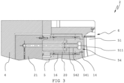
- the figure 3 shows a vertical sectional view through one of the areas 511 from FIG figure 2 . From this sectional view it can be seen that the area 511 is formed as part of the inner wall 51 .
- the region 511 has an associated section which is designed as a molded part 20 which is designed separately from the molded body 5 .
- the molded part 20 is embedded in the molded body 5 at its end facing the mold cavity 6 and is subsequently spaced apart from the molded body 5 in the direction of the base plate 4 by an insulating element 16 .
- the insulation element 16 is additionally spaced from the shaped body 5 by two O-rings.
- the tempering channels 54 are formed within the molded part 20 .
- a bore 541 is provided in molded part 20, into which a tube 542 opens or this bore 541 penetrates along its length, so that an annular gap is formed between tube 542 under the inner wall of bore 541, through which the temperature control medium is guided in the vicinity of region 511 can be, or can be discharged from this.
- the pipe 542 opens into a corresponding channel on the distributor block 521 and the annular gap correspondingly opens into another channel on the distributor block 21. These channels open into the connections 211 and 212 respectively (see figure 2 ).
- the cooling channel 54 has an extension at its end lying adjacent to the region 511, so that the cooling channel 54 forms a chamber.
- This chamber connects the annular gap and the Tube so that a cooling circuit can be provided.
- the chamber is spaced apart from the mold cavity 6 with a wall thickness which is 3 mm in the present case. This ensures that the heat that this wall thickness has, for example after blow molding, can be dissipated quickly, or that the wall thickness can be heated up quickly with a suitable heating medium so that its temperature essentially corresponds to that of the preform that is placed in the mold cavity 6 is introduced for blow molding.
- first area 511 of mold cavity 6 of molded body 5 of a first blow mold half 2 of blow molding tool 1 is heated by supplying a temperature control medium through separate temperature control channels 54 heated up.
- the preform is then introduced into the mold cavity 6 .
- the blow molding tool 1 is then closed and the plastic container is formed by inflating the preform and placing the preform against the inner wall 51 of the mold cavity 6 .
- the area is cooled by supplying a cooling medium through the temperature control channels 54 and the plastic container is removed from the mold when a specific cooling temperature is reached.
Landscapes
- Engineering & Computer Science (AREA)
- Manufacturing & Machinery (AREA)
- Mechanical Engineering (AREA)
- Physics & Mathematics (AREA)
- Thermal Sciences (AREA)
- Moulds For Moulding Plastics Or The Like (AREA)
- Blow-Moulding Or Thermoforming Of Plastics Or The Like (AREA)
Claims (21)
- Outil de moulage par soufflage (1) destiné à une machine de moulage par soufflage (1), en particulier un outil de moulage par extrusion-soufflage, présentant au moins un premier demi-moule de soufflage (2) et un deuxième demi-moule de soufflage (3), le premier demi-moule de soufflage (2) présentant une plaque de base (4) et un corps de moule (5), au moins une cavité (6), dotée d'une paroi interne (51), étant disposée dans le corps de moule (5),caractérisé en ce que
au moins une zone (511) de la paroi interne (51) de la cavité (6) présente, dans sa partie associée du corps de moule (5), des canaux de régulation de température (54) séparés, destinés à la régulation de température de la zone (54). - Outil de moulage par soufflage (1) selon la revendication 1, caractérisé en ce que
la zone (511), avec sa partie associée, est formée sur une partie de moule (20) réalisée séparément par rapport au corps de moule (5). - Outil de moulage par soufflage (1) selon la revendication 2, caractérisé en ce que
la partie de moule (20) est réalisée en aluminium ou un alliage de celui-ci. - Outil de moulage par soufflage (1) selon la revendication 2 ou 3, caractérisé en ce que
un élément isolant (16), constitué d'un matériau thermiquement isolant, est disposé entre la partie de moule (20) et le corps de moule (5). - Outil de moulage par soufflage (1) selon l'une des revendications 1 à 4, caractérisé en ce que l'élément isolant (16) est constitué d'une matière plastique thermodurcissable, résistant aux hautes températures et présentant une faible conductivité thermique.
- Outil de moulage par soufflage (1) selon l'une des revendications 1 à 5, caractérisé en ce que entre la plaque de base (4) et le corps de moule (5), il est prévu un bloc de distribution (21) destiné à l'alimentation des canaux de régulation de température (54).
- Outil de moulage par soufflage (1) selon l'une des revendications 1 à 6, caractérisé en ce que le bloc de distribution (21) est réalisé en aluminium ou un alliage de celui-ci.
- Outil de moulage par soufflage (1) selon l'une des revendications 6 ou 7, caractérisé en ce que le bloc de distribution (21) présente des raccords pour l'arrivée et l'évacuation d'un fluide de chauffage/refroidissement vers les canaux de régulation de température (54).
- Outil de moulage par soufflage (1) selon l'une des revendications 1 à 8, caractérisé en ce que le corps de moule (5) est réalisé en plusieurs parties et présente un insert formant col (18) et/ou une partie de fond (10).
- Outil de moulage par soufflage (1) selon l'une des revendications 1 à 9, caractérisé en ce que la plaque de base (4) est réalisée en acier inoxydable.
- Outil de moulage par soufflage (1) selon l'une des revendications 1 à 10, caractérisé en ce que le corps de moule (5) est réalisé en aluminium ou un alliage de celui-ci.
- Outil de moulage par soufflage (1) selon l'une des revendications 1 à 11, caractérisé en ce que les canaux de régulation de température (54) sont réalisés sous forme de trou (541), un tube (542) étant disposé de façon concentrique à l'intérieur du trou (541), de sorte qu'un espace annulaire se forme en tant que canal de régulation de température (54) entre le tube (541) et le trou (542).
- Outil de moulage par soufflage (1) selon l'une des revendications 1 à 12, caractérisé en ce que une épaisseur de paroi entre le canal de régulation de température (54) et la zone (511) est au minimum de 1,5 mm et au maximum de 12 mm.
- Outil de moulage par soufflage (1) selon l'une des revendications 1 à 13, caractérisé en ce que la zone (511) présente une surface structurée.
- Machine de moulage par extrusion-soufflage, présentant un outil de moulage par soufflage (1) selon l'une des revendications 1 à 14.
- Procédé de traitement thermique d'une zone partielle d'une surface d'un récipient en matière plastique, avec un outil de moulage par soufflage (1), en particulier avec un outil de moulage par soufflage (1) selon l'une des revendications 1 à 15, comprenant les étapes suivants :- chauffage d'une zone (511) d'une cavité (13) d'un corps de moule (5) d'un premier demi-moule de soufflage (2) de l'outil de moulage par soufflage (1), par apport d'un fluide de chauffage à travers des canaux de régulation de température (54) séparés,- mise en place d'une préforme dans la cavité (6),- fermeture de l'outil de moulage par soufflage (1),- mise en forme du récipient en matière plastique par soufflage de la préforme et par application de la préforme contre la paroi interne de la cavité (6),- refroidissement de la zone (511) par apport d'un fluide de refroidissement à travers les canaux de régulation de température (54),- démoulage du récipient en matière plastique.
- Procédé selon la revendication 16, caractérisé en ce que
pendant la mise en forme du récipient en matière plastique, la zone (511) présente une température qui est augmentée par rapport à une température de la paroi interne restante de la cavité (6). - Procédé selon la revendication 16 ou 17, caractérisé en ce que
lors du refroidissement, la zone (511) est refroidie à une vitesse de refroidissement moyenne d'au moins 5 K/s, de préférence 15 K/s, et de manière particulièrement avantageuse de 30 K/s. - Procédé selon l'une des revendications 16 à 18, caractérisé en ce que
pendant le refroidissement de la zone (511), le corps de moule (5) est également refroidi. - Procédé selon l'une des revendications 16 à 19, caractérisé en ce que
l'on utilise de l'eau à température régulée en tant que fluide de chauffage et en tant que fluide de refroidissement. - Procédé selon l'une des revendications 16 à 20, caractérisé en ce que
la préforme est constituée pour l'essentiel d'une polyoléfine, et en ce que le fluide de chauffage est apporté à une température allant de 120 °C à 200 °C, de préférence de 160 C, et le fluide de refroidissement est apporté à une température allant de 5 °C à 40 °C, de préférence de 15 °C.
Applications Claiming Priority (2)
| Application Number | Priority Date | Filing Date | Title |
|---|---|---|---|
| CH00413/19A CH716011A1 (de) | 2019-03-29 | 2019-03-29 | Blasformwerkzeug für eine Blasformmaschine. |
| PCT/EP2020/058665 WO2020201062A1 (fr) | 2019-03-29 | 2020-03-27 | Outil de moulage par soufflage et procédé pour le traitement thermique d'une zone partielle d'une surface d'un récipient en plastique |
Publications (3)
| Publication Number | Publication Date |
|---|---|
| EP3946889A1 EP3946889A1 (fr) | 2022-02-09 |
| EP3946889B1 true EP3946889B1 (fr) | 2023-06-07 |
| EP3946889C0 EP3946889C0 (fr) | 2023-06-07 |
Family
ID=66091823
Family Applications (3)
| Application Number | Title | Priority Date | Filing Date |
|---|---|---|---|
| EP20715051.7A Active EP3946888B1 (fr) | 2019-03-29 | 2020-03-27 | Outil de soufflage sur matrice pour une machine de soufflage sur matrice |
| EP20715052.5A Active EP3946889B1 (fr) | 2019-03-29 | 2020-03-27 | Outil de moulage par soufflage et procédé pour le traitement thermique d'une zone partielle d'une surface d'un récipient en plastique |
| EP20715338.8A Active EP3946890B1 (fr) | 2019-03-29 | 2020-03-27 | Procédé de transfert d'une structure négative d'une surface d'une paroi intérieure d'un moule de soufflage et récipient en plastique |
Family Applications Before (1)
| Application Number | Title | Priority Date | Filing Date |
|---|---|---|---|
| EP20715051.7A Active EP3946888B1 (fr) | 2019-03-29 | 2020-03-27 | Outil de soufflage sur matrice pour une machine de soufflage sur matrice |
Family Applications After (1)
| Application Number | Title | Priority Date | Filing Date |
|---|---|---|---|
| EP20715338.8A Active EP3946890B1 (fr) | 2019-03-29 | 2020-03-27 | Procédé de transfert d'une structure négative d'une surface d'une paroi intérieure d'un moule de soufflage et récipient en plastique |
Country Status (8)
| Country | Link |
|---|---|
| US (3) | US12064915B2 (fr) |
| EP (3) | EP3946888B1 (fr) |
| CN (3) | CN113661045B (fr) |
| CH (1) | CH716011A1 (fr) |
| MX (3) | MX2021011518A (fr) |
| PL (2) | PL3946889T3 (fr) |
| WO (3) | WO2020201061A1 (fr) |
| ZA (3) | ZA202106099B (fr) |
Families Citing this family (7)
| Publication number | Priority date | Publication date | Assignee | Title |
|---|---|---|---|---|
| CH716011A1 (de) | 2019-03-29 | 2020-09-30 | Alpla Werke Alwin Lehner Gmbh & Co Kg | Blasformwerkzeug für eine Blasformmaschine. |
| FR3100474B1 (fr) * | 2019-09-11 | 2022-12-16 | Sidel Participations | Procédé de fabrication d’un récipient en matière plastique, comprenant un refroidissement non réfrigéré d’un fond de moule |
| CH717886A1 (de) | 2020-09-21 | 2022-03-31 | Alpla Werke Alwin Lehner Gmbh & Co Kg | Kunststoffbehälter und Verfahren zum Bestimmen einer Eigenschaft eines Kunststoffbehälters. |
| CH718218A1 (de) * | 2020-12-28 | 2022-06-30 | Alpla Werke Alwin Lehner Gmbh & Co Kg | Formkörper für ein Blasformwerkzeug und Blasformwerkzeug. |
| DE102023001403B3 (de) | 2023-04-11 | 2023-12-14 | Kocher-Plastik Maschinenbau Gmbh | Vorrichtung nebst zugehöriger Formwerkzeuge und System bestehend aus einem Satz von Formwerkzeugen |
| US20240359391A1 (en) * | 2023-04-27 | 2024-10-31 | Plastipak Packaging, Inc. | Mold insert, mold assembly, and system |
| CN116714224B (zh) * | 2023-08-08 | 2023-10-24 | 青州市鲁冠塑料有限公司 | 一种塑料吹塑成型设备 |
Family Cites Families (26)
| Publication number | Priority date | Publication date | Assignee | Title |
|---|---|---|---|---|
| DE2339019A1 (de) | 1973-08-01 | 1975-02-13 | 4 P Verpackungen Gmbh | Verfahren und vorrichtung zur herstellung von hohlkoerpern durch aufblasen von vorformlingen |
| US4206171A (en) | 1976-12-06 | 1980-06-03 | Owens-Illinois, Inc. | Method for thermal conditioning a thermoplastic parison |
| DE3301337A1 (de) | 1983-01-17 | 1984-07-19 | Holger 5609 Hückeswagen Buchner | Verfahren zur herstellung einer kuehleinrichtung an werkzeugen zur formgebung von kunststoffen und das mit einer solchen kuehleinrichtung ausgestattete werkzeug |
| US5041247A (en) * | 1988-09-29 | 1991-08-20 | General Electric Company | Method and apparatus for blow molding parts with smooth surfaces |
| GB2239626A (en) | 1990-01-09 | 1991-07-10 | William Douglas Lamb | A method of making a mould provided with cooling means |
| JPH0740426A (ja) * | 1993-07-28 | 1995-02-10 | Toppan Printing Co Ltd | ホログラムを有する中空容器及びその製造方法 |
| JP2795144B2 (ja) | 1993-10-07 | 1998-09-10 | ジェイエスアール株式会社 | 成形用金型 |
| JP3414473B2 (ja) * | 1994-02-02 | 2003-06-09 | 旭化成株式会社 | 樹脂成形用金型 |
| AU704903B2 (en) | 1995-03-27 | 1999-05-06 | Kurt H. Ruppman Sr. | Method of making a molded plastic container |
| WO1999033634A1 (fr) | 1997-12-26 | 1999-07-08 | Nippon Steel Chemical Co., Ltd. | Dispositif de moulage par soufflage et procede de moulage |
| AU1161899A (en) | 1998-11-10 | 2000-05-29 | Clair Costanzo | Mould and method for moulding axially compressible tubular objects in semirigid plastic material, and resulting products |
| BRPI0511664A (pt) * | 2004-06-10 | 2008-01-02 | Advanced Plastics Technologies | métodos e sistemas para o controle de temperaturas de moldes |
| ATE454976T1 (de) | 2004-06-28 | 2010-01-15 | Alpla Werke | Herstellverfahren und extrusionsblasmaschine für kunststoffbehälter |
| FR2939073B1 (fr) | 2008-12-03 | 2010-12-31 | Sidel Participations | Formage des recipients avec contre-pression localisee |
| DE102009005142A1 (de) * | 2009-01-15 | 2010-07-22 | Krones Ag | Streckblasmaschine mit beheizbarer Blasform |
| US8808610B2 (en) * | 2009-04-01 | 2014-08-19 | Patrick E. Scharf | Systems and methods for cooling moving molds |
| DE102010020090B4 (de) | 2010-05-10 | 2013-07-18 | Kautex Maschinenbau Gmbh | Werkzeug zur Formung von Artikeln aus thermoplastischem Kunststoff |
| AU2012223125B2 (en) | 2011-02-21 | 2016-09-08 | Grail Inventions (Pty) Ltd. | A mould assembly. |
| FR2982789B1 (fr) * | 2011-11-22 | 2014-08-01 | Sidel Participations | Dispositif d'isolation thermique pour moule, moule equipe d'un tel dispositif et installation comprenant au moins un tel moule. |
| FR2994880B1 (fr) | 2012-08-28 | 2014-08-29 | Sidel Participations | "procede de refroidissement d'un moule par circulation d'un fluide caloporteur au contact de sa face externe" |
| DE102013113335A1 (de) | 2013-12-02 | 2015-06-03 | Krones Ag | Blasformmaschine mit erwärmbarer Kühlmittelzuführung |
| EP3268206B1 (fr) | 2015-03-09 | 2020-11-25 | Graham Packaging Company, L.P. | Procédés, ensembles, systèmes et pré-ensembles de stade intermédiaire de récipients à chambres multiples pour fabriquer un récipient à chambres multiples |
| MX2018000041A (es) | 2015-06-26 | 2018-03-12 | Procter & Gamble | Recipiente brillante. |
| FR3038541B1 (fr) * | 2015-07-08 | 2017-07-21 | Sidel Participations | Dispositif de moulage pour une machine de fabrication de recipients en matiere thermoplastique |
| FR3053906B1 (fr) * | 2016-12-12 | 2018-08-17 | Sidel Participations | Dispositif de moulage pour la mise en œuvre de procedes de moulage a chaud et de moulage a froid |
| CH716011A1 (de) * | 2019-03-29 | 2020-09-30 | Alpla Werke Alwin Lehner Gmbh & Co Kg | Blasformwerkzeug für eine Blasformmaschine. |
-
2019
- 2019-03-29 CH CH00413/19A patent/CH716011A1/de not_active Application Discontinuation
-
2020
- 2020-03-27 EP EP20715051.7A patent/EP3946888B1/fr active Active
- 2020-03-27 MX MX2021011518A patent/MX2021011518A/es unknown
- 2020-03-27 CN CN202080025161.XA patent/CN113661045B/zh active Active
- 2020-03-27 WO PCT/EP2020/058664 patent/WO2020201061A1/fr not_active Ceased
- 2020-03-27 PL PL20715052.5T patent/PL3946889T3/pl unknown
- 2020-03-27 WO PCT/EP2020/058665 patent/WO2020201062A1/fr not_active Ceased
- 2020-03-27 PL PL20715051.7T patent/PL3946888T3/pl unknown
- 2020-03-27 US US17/599,760 patent/US12064915B2/en active Active
- 2020-03-27 EP EP20715052.5A patent/EP3946889B1/fr active Active
- 2020-03-27 MX MX2021011525A patent/MX2021011525A/es unknown
- 2020-03-27 EP EP20715338.8A patent/EP3946890B1/fr active Active
- 2020-03-27 WO PCT/EP2020/058666 patent/WO2020201063A1/fr not_active Ceased
- 2020-03-27 MX MX2021011526A patent/MX2021011526A/es unknown
- 2020-03-27 CN CN202080025164.3A patent/CN113631349B/zh active Active
- 2020-03-27 US US17/599,774 patent/US12030234B2/en active Active
- 2020-03-27 US US17/599,769 patent/US11975474B2/en active Active
- 2020-03-27 CN CN202080025162.4A patent/CN113631348A/zh active Pending
-
2021
- 2021-08-24 ZA ZA2021/06099A patent/ZA202106099B/en unknown
- 2021-08-24 ZA ZA2021/06098A patent/ZA202106098B/en unknown
- 2021-08-24 ZA ZA2021/06100A patent/ZA202106100B/en unknown
Also Published As
Similar Documents
| Publication | Publication Date | Title |
|---|---|---|
| EP3946889B1 (fr) | Outil de moulage par soufflage et procédé pour le traitement thermique d'une zone partielle d'une surface d'un récipient en plastique | |
| EP2026947B1 (fr) | Procédé de fabrication de corps creux à partir de matière thermoplastique par moulage par extrusion-soufflage avec ajustement continu de l'ouverture des buses | |
| DE69328561T2 (de) | Blasformling, verfahren und vorrichtung | |
| EP3055120B1 (fr) | Procédé et dispositif pour la production d'un récipient rempli de matière de remplissage | |
| DE102012004613A1 (de) | Verfahren und Vorrichtung zur Herstellung einer optimierten Bodenkontur von Preformen | |
| EP2113368B1 (fr) | Dispositif de formage par soufflage | |
| EP2332715A2 (fr) | Machine de formage par soufflage doté d'un dispositif de refroidissement | |
| DE102006032140A1 (de) | Verfahren und Vorrichtung zur Blasformung von Behältern | |
| EP1660301B2 (fr) | Procede et dispositif de moulage par soufflage de recipients | |
| WO2005023520A1 (fr) | Procede et dispositif de moulage par soufflage de recipients | |
| EP2352632A2 (fr) | Dispositif et procédé de fabrication de contenants en plastique et contenant en plastique fabriqué par ce procédé | |
| EP3197655B1 (fr) | Procédé et dispositif pour réaliser un contour de col optimisé sur des préformes | |
| DE102004018146A1 (de) | Verfahren und Vorrichtung zur Blasformung von Behältern | |
| EP1732743B1 (fr) | Procede et dispositif de moulage de contenants par soufflage, faisant appel a une vitesse d'augmentation de pression reduite | |
| WO2007063063A1 (fr) | Procede de post-traitement et dispositif approprie | |
| DE1704292A1 (de) | Verfahren zum Ausformen von Gegenstaenden aus thermoplastischen Kunststoffen | |
| EP2129508B1 (fr) | Procédé de moulage par soufflage de contenants | |
| EP4267369B1 (fr) | Corps de moule pour un moule de soufflage, et moule de soufflage | |
| EP4724256A1 (fr) | Machine d'extrusion-soufflage et procédé de fabrication d'un corps creux | |
| DE102005032403A1 (de) | Verfahren und Vorrichtung zur Blasformung von Behältern | |
| DE3827772A1 (de) | Vorrichtung und verfahren zur formgebung von halbzeug aus hochmolekularen kunststoffen | |
| DE4107011A1 (de) | Verfahren und vorrichtung zum herstellen blasgeformter hohlkoerper | |
| DE102004003939A1 (de) | Verfahren und Vorrichtung zur Blasformung von Behältern | |
| DE10026368A1 (de) | Verfahren und Vorrichtung zur Herstellung von Vorformlingen | |
| DE102004050531A1 (de) | Verfahren und Vorrichtung zur Blasformung von Behältern |
Legal Events
| Date | Code | Title | Description |
|---|---|---|---|
| STAA | Information on the status of an ep patent application or granted ep patent |
Free format text: STATUS: UNKNOWN |
|
| STAA | Information on the status of an ep patent application or granted ep patent |
Free format text: STATUS: THE INTERNATIONAL PUBLICATION HAS BEEN MADE |
|
| PUAI | Public reference made under article 153(3) epc to a published international application that has entered the european phase |
Free format text: ORIGINAL CODE: 0009012 |
|
| STAA | Information on the status of an ep patent application or granted ep patent |
Free format text: STATUS: REQUEST FOR EXAMINATION WAS MADE |
|
| 17P | Request for examination filed |
Effective date: 20211020 |
|
| AK | Designated contracting states |
Kind code of ref document: A1 Designated state(s): AL AT BE BG CH CY CZ DE DK EE ES FI FR GB GR HR HU IE IS IT LI LT LU LV MC MK MT NL NO PL PT RO RS SE SI SK SM TR |
|
| DAV | Request for validation of the european patent (deleted) | ||
| DAX | Request for extension of the european patent (deleted) | ||
| GRAP | Despatch of communication of intention to grant a patent |
Free format text: ORIGINAL CODE: EPIDOSNIGR1 |
|
| STAA | Information on the status of an ep patent application or granted ep patent |
Free format text: STATUS: GRANT OF PATENT IS INTENDED |
|
| RIC1 | Information provided on ipc code assigned before grant |
Ipc: B29K 23/00 20060101ALN20220929BHEP Ipc: B29L 31/00 20060101ALN20220929BHEP Ipc: B29K 67/00 20060101ALN20220929BHEP Ipc: B29C 49/06 20060101ALN20220929BHEP Ipc: B29C 49/48 20060101AFI20220929BHEP |
|
| INTG | Intention to grant announced |
Effective date: 20221021 |
|
| GRAJ | Information related to disapproval of communication of intention to grant by the applicant or resumption of examination proceedings by the epo deleted |
Free format text: ORIGINAL CODE: EPIDOSDIGR1 |
|
| STAA | Information on the status of an ep patent application or granted ep patent |
Free format text: STATUS: REQUEST FOR EXAMINATION WAS MADE |
|
| GRAP | Despatch of communication of intention to grant a patent |
Free format text: ORIGINAL CODE: EPIDOSNIGR1 |
|
| STAA | Information on the status of an ep patent application or granted ep patent |
Free format text: STATUS: GRANT OF PATENT IS INTENDED |
|
| INTC | Intention to grant announced (deleted) | ||
| RIC1 | Information provided on ipc code assigned before grant |
Ipc: B29K 23/00 20060101ALN20230210BHEP Ipc: B29L 31/00 20060101ALN20230210BHEP Ipc: B29K 67/00 20060101ALN20230210BHEP Ipc: B29C 49/06 20060101ALN20230210BHEP Ipc: B29C 49/48 20060101AFI20230210BHEP |
|
| INTG | Intention to grant announced |
Effective date: 20230302 |
|
| GRAS | Grant fee paid |
Free format text: ORIGINAL CODE: EPIDOSNIGR3 |
|
| GRAA | (expected) grant |
Free format text: ORIGINAL CODE: 0009210 |
|
| STAA | Information on the status of an ep patent application or granted ep patent |
Free format text: STATUS: THE PATENT HAS BEEN GRANTED |
|
| AK | Designated contracting states |
Kind code of ref document: B1 Designated state(s): AL AT BE BG CH CY CZ DE DK EE ES FI FR GB GR HR HU IE IS IT LI LT LU LV MC MK MT NL NO PL PT RO RS SE SI SK SM TR |
|
| REG | Reference to a national code |
Ref country code: GB Ref legal event code: FG4D Free format text: NOT ENGLISH |
|
| REG | Reference to a national code |
Ref country code: CH Ref legal event code: EP Ref country code: AT Ref legal event code: REF Ref document number: 1573733 Country of ref document: AT Kind code of ref document: T Effective date: 20230615 |
|
| REG | Reference to a national code |
Ref country code: DE Ref legal event code: R096 Ref document number: 502020003664 Country of ref document: DE |
|
| U01 | Request for unitary effect filed |
Effective date: 20230607 |
|
| U07 | Unitary effect registered |
Designated state(s): AT BE BG DE DK EE FI FR IT LT LU LV MT NL PT SE SI Effective date: 20230612 |
|
| REG | Reference to a national code |
Ref country code: LT Ref legal event code: MG9D |
|
| PG25 | Lapsed in a contracting state [announced via postgrant information from national office to epo] |
Ref country code: NO Free format text: LAPSE BECAUSE OF FAILURE TO SUBMIT A TRANSLATION OF THE DESCRIPTION OR TO PAY THE FEE WITHIN THE PRESCRIBED TIME-LIMIT Effective date: 20230907 |
|
| REG | Reference to a national code |
Ref country code: ES Ref legal event code: FG2A Ref document number: 2952514 Country of ref document: ES Kind code of ref document: T3 Effective date: 20231031 |
|
| PG25 | Lapsed in a contracting state [announced via postgrant information from national office to epo] |
Ref country code: RS Free format text: LAPSE BECAUSE OF FAILURE TO SUBMIT A TRANSLATION OF THE DESCRIPTION OR TO PAY THE FEE WITHIN THE PRESCRIBED TIME-LIMIT Effective date: 20230607 Ref country code: HR Free format text: LAPSE BECAUSE OF FAILURE TO SUBMIT A TRANSLATION OF THE DESCRIPTION OR TO PAY THE FEE WITHIN THE PRESCRIBED TIME-LIMIT Effective date: 20230607 Ref country code: GR Free format text: LAPSE BECAUSE OF FAILURE TO SUBMIT A TRANSLATION OF THE DESCRIPTION OR TO PAY THE FEE WITHIN THE PRESCRIBED TIME-LIMIT Effective date: 20230908 |
|
| PG25 | Lapsed in a contracting state [announced via postgrant information from national office to epo] |
Ref country code: SK Free format text: LAPSE BECAUSE OF FAILURE TO SUBMIT A TRANSLATION OF THE DESCRIPTION OR TO PAY THE FEE WITHIN THE PRESCRIBED TIME-LIMIT Effective date: 20230607 |
|
| PG25 | Lapsed in a contracting state [announced via postgrant information from national office to epo] |
Ref country code: IS Free format text: LAPSE BECAUSE OF FAILURE TO SUBMIT A TRANSLATION OF THE DESCRIPTION OR TO PAY THE FEE WITHIN THE PRESCRIBED TIME-LIMIT Effective date: 20231007 |
|
| PG25 | Lapsed in a contracting state [announced via postgrant information from national office to epo] |
Ref country code: SM Free format text: LAPSE BECAUSE OF FAILURE TO SUBMIT A TRANSLATION OF THE DESCRIPTION OR TO PAY THE FEE WITHIN THE PRESCRIBED TIME-LIMIT Effective date: 20230607 Ref country code: SK Free format text: LAPSE BECAUSE OF FAILURE TO SUBMIT A TRANSLATION OF THE DESCRIPTION OR TO PAY THE FEE WITHIN THE PRESCRIBED TIME-LIMIT Effective date: 20230607 Ref country code: RO Free format text: LAPSE BECAUSE OF FAILURE TO SUBMIT A TRANSLATION OF THE DESCRIPTION OR TO PAY THE FEE WITHIN THE PRESCRIBED TIME-LIMIT Effective date: 20230607 Ref country code: IS Free format text: LAPSE BECAUSE OF FAILURE TO SUBMIT A TRANSLATION OF THE DESCRIPTION OR TO PAY THE FEE WITHIN THE PRESCRIBED TIME-LIMIT Effective date: 20231007 Ref country code: CZ Free format text: LAPSE BECAUSE OF FAILURE TO SUBMIT A TRANSLATION OF THE DESCRIPTION OR TO PAY THE FEE WITHIN THE PRESCRIBED TIME-LIMIT Effective date: 20230607 |
|
| REG | Reference to a national code |
Ref country code: DE Ref legal event code: R097 Ref document number: 502020003664 Country of ref document: DE |
|
| PLBE | No opposition filed within time limit |
Free format text: ORIGINAL CODE: 0009261 |
|
| STAA | Information on the status of an ep patent application or granted ep patent |
Free format text: STATUS: NO OPPOSITION FILED WITHIN TIME LIMIT |
|
| U20 | Renewal fee for the european patent with unitary effect paid |
Year of fee payment: 5 Effective date: 20240325 |
|
| 26N | No opposition filed |
Effective date: 20240308 |
|
| PG25 | Lapsed in a contracting state [announced via postgrant information from national office to epo] |
Ref country code: MC Free format text: LAPSE BECAUSE OF FAILURE TO SUBMIT A TRANSLATION OF THE DESCRIPTION OR TO PAY THE FEE WITHIN THE PRESCRIBED TIME-LIMIT Effective date: 20230607 |
|
| PG25 | Lapsed in a contracting state [announced via postgrant information from national office to epo] |
Ref country code: MC Free format text: LAPSE BECAUSE OF FAILURE TO SUBMIT A TRANSLATION OF THE DESCRIPTION OR TO PAY THE FEE WITHIN THE PRESCRIBED TIME-LIMIT Effective date: 20230607 |
|
| PG25 | Lapsed in a contracting state [announced via postgrant information from national office to epo] |
Ref country code: IE Free format text: LAPSE BECAUSE OF NON-PAYMENT OF DUE FEES Effective date: 20240327 |
|
| PG25 | Lapsed in a contracting state [announced via postgrant information from national office to epo] |
Ref country code: IE Free format text: LAPSE BECAUSE OF NON-PAYMENT OF DUE FEES Effective date: 20240327 |
|
| U20 | Renewal fee for the european patent with unitary effect paid |
Year of fee payment: 6 Effective date: 20250325 |
|
| PGFP | Annual fee paid to national office [announced via postgrant information from national office to epo] |
Ref country code: ES Payment date: 20250416 Year of fee payment: 6 |
|
| PGFP | Annual fee paid to national office [announced via postgrant information from national office to epo] |
Ref country code: CH Payment date: 20250401 Year of fee payment: 6 |
|
| PG25 | Lapsed in a contracting state [announced via postgrant information from national office to epo] |
Ref country code: CY Free format text: LAPSE BECAUSE OF FAILURE TO SUBMIT A TRANSLATION OF THE DESCRIPTION OR TO PAY THE FEE WITHIN THE PRESCRIBED TIME-LIMIT; INVALID AB INITIO Effective date: 20200327 |
|
| PG25 | Lapsed in a contracting state [announced via postgrant information from national office to epo] |
Ref country code: HU Free format text: LAPSE BECAUSE OF FAILURE TO SUBMIT A TRANSLATION OF THE DESCRIPTION OR TO PAY THE FEE WITHIN THE PRESCRIBED TIME-LIMIT; INVALID AB INITIO Effective date: 20200327 |
|
| PG25 | Lapsed in a contracting state [announced via postgrant information from national office to epo] |
Ref country code: TR Free format text: LAPSE BECAUSE OF FAILURE TO SUBMIT A TRANSLATION OF THE DESCRIPTION OR TO PAY THE FEE WITHIN THE PRESCRIBED TIME-LIMIT Effective date: 20230607 |
|
| REG | Reference to a national code |
Ref country code: CH Ref legal event code: U11 Free format text: ST27 STATUS EVENT CODE: U-0-0-U10-U11 (AS PROVIDED BY THE NATIONAL OFFICE) Effective date: 20260401 |
|
| PGFP | Annual fee paid to national office [announced via postgrant information from national office to epo] |
Ref country code: GB Payment date: 20260324 Year of fee payment: 7 |
|
| PGFP | Annual fee paid to national office [announced via postgrant information from national office to epo] |
Ref country code: PL Payment date: 20260317 Year of fee payment: 7 |