EP3947085B1 - Procédé et unité de commande pour déterminer un paramètre indiquant la capacité de route d'un segment de route supportant un véhicule - Google Patents
Procédé et unité de commande pour déterminer un paramètre indiquant la capacité de route d'un segment de route supportant un véhicule Download PDFInfo
- Publication number
- EP3947085B1 EP3947085B1 EP19718089.6A EP19718089A EP3947085B1 EP 3947085 B1 EP3947085 B1 EP 3947085B1 EP 19718089 A EP19718089 A EP 19718089A EP 3947085 B1 EP3947085 B1 EP 3947085B1
- Authority
- EP
- European Patent Office
- Prior art keywords
- ground engaging
- engaging member
- vehicle
- engaging members
- control unit
- Prior art date
- Legal status (The legal status is an assumption and is not a legal conclusion. Google has not performed a legal analysis and makes no representation as to the accuracy of the status listed.)
- Active
Links
Images


Classifications
-
- B—PERFORMING OPERATIONS; TRANSPORTING
- B60—VEHICLES IN GENERAL
- B60G—VEHICLE SUSPENSION ARRANGEMENTS
- B60G17/00—Resilient suspensions having means for adjusting the spring or vibration-damper characteristics, for regulating the distance between a supporting surface and a sprung part of vehicle or for locking suspension during use to meet varying vehicular or surface conditions, e.g. due to speed or load
- B60G17/015—Resilient suspensions having means for adjusting the spring or vibration-damper characteristics, for regulating the distance between a supporting surface and a sprung part of vehicle or for locking suspension during use to meet varying vehicular or surface conditions, e.g. due to speed or load the regulating means comprising electric or electronic elements
- B60G17/018—Resilient suspensions having means for adjusting the spring or vibration-damper characteristics, for regulating the distance between a supporting surface and a sprung part of vehicle or for locking suspension during use to meet varying vehicular or surface conditions, e.g. due to speed or load the regulating means comprising electric or electronic elements characterised by the use of a specific signal treatment or control method
- B60G17/0182—Resilient suspensions having means for adjusting the spring or vibration-damper characteristics, for regulating the distance between a supporting surface and a sprung part of vehicle or for locking suspension during use to meet varying vehicular or surface conditions, e.g. due to speed or load the regulating means comprising electric or electronic elements characterised by the use of a specific signal treatment or control method involving parameter estimation, e.g. observer, Kalman filter
-
- B—PERFORMING OPERATIONS; TRANSPORTING
- B60—VEHICLES IN GENERAL
- B60W—CONJOINT CONTROL OF VEHICLE SUB-UNITS OF DIFFERENT TYPE OR DIFFERENT FUNCTION; CONTROL SYSTEMS SPECIALLY ADAPTED FOR HYBRID VEHICLES; ROAD VEHICLE DRIVE CONTROL SYSTEMS FOR PURPOSES NOT RELATED TO THE CONTROL OF A PARTICULAR SUB-UNIT
- B60W40/00—Estimation or calculation of non-directly measurable driving parameters for road vehicle drive control systems not related to the control of a particular sub unit, e.g. by using mathematical models
- B60W40/02—Estimation or calculation of non-directly measurable driving parameters for road vehicle drive control systems not related to the control of a particular sub unit, e.g. by using mathematical models related to ambient conditions
- B60W40/06—Road conditions
-
- B—PERFORMING OPERATIONS; TRANSPORTING
- B60—VEHICLES IN GENERAL
- B60G—VEHICLE SUSPENSION ARRANGEMENTS
- B60G17/00—Resilient suspensions having means for adjusting the spring or vibration-damper characteristics, for regulating the distance between a supporting surface and a sprung part of vehicle or for locking suspension during use to meet varying vehicular or surface conditions, e.g. due to speed or load
- B60G17/015—Resilient suspensions having means for adjusting the spring or vibration-damper characteristics, for regulating the distance between a supporting surface and a sprung part of vehicle or for locking suspension during use to meet varying vehicular or surface conditions, e.g. due to speed or load the regulating means comprising electric or electronic elements
- B60G17/0195—Resilient suspensions having means for adjusting the spring or vibration-damper characteristics, for regulating the distance between a supporting surface and a sprung part of vehicle or for locking suspension during use to meet varying vehicular or surface conditions, e.g. due to speed or load the regulating means comprising electric or electronic elements characterised by the regulation being combined with other vehicle control systems
-
- B—PERFORMING OPERATIONS; TRANSPORTING
- B60—VEHICLES IN GENERAL
- B60W—CONJOINT CONTROL OF VEHICLE SUB-UNITS OF DIFFERENT TYPE OR DIFFERENT FUNCTION; CONTROL SYSTEMS SPECIALLY ADAPTED FOR HYBRID VEHICLES; ROAD VEHICLE DRIVE CONTROL SYSTEMS FOR PURPOSES NOT RELATED TO THE CONTROL OF A PARTICULAR SUB-UNIT
- B60W10/00—Conjoint control of vehicle sub-units of different type or different function
- B60W10/22—Conjoint control of vehicle sub-units of different type or different function including control of suspension systems
-
- B—PERFORMING OPERATIONS; TRANSPORTING
- B60—VEHICLES IN GENERAL
- B60W—CONJOINT CONTROL OF VEHICLE SUB-UNITS OF DIFFERENT TYPE OR DIFFERENT FUNCTION; CONTROL SYSTEMS SPECIALLY ADAPTED FOR HYBRID VEHICLES; ROAD VEHICLE DRIVE CONTROL SYSTEMS FOR PURPOSES NOT RELATED TO THE CONTROL OF A PARTICULAR SUB-UNIT
- B60W40/00—Estimation or calculation of non-directly measurable driving parameters for road vehicle drive control systems not related to the control of a particular sub unit, e.g. by using mathematical models
- B60W40/02—Estimation or calculation of non-directly measurable driving parameters for road vehicle drive control systems not related to the control of a particular sub unit, e.g. by using mathematical models related to ambient conditions
- B60W40/06—Road conditions
- B60W40/068—Road friction coefficient
-
- B—PERFORMING OPERATIONS; TRANSPORTING
- B60—VEHICLES IN GENERAL
- B60G—VEHICLE SUSPENSION ARRANGEMENTS
- B60G2202/00—Indexing codes relating to the type of spring, damper or actuator
- B60G2202/10—Type of spring
- B60G2202/15—Fluid spring
- B60G2202/152—Pneumatic spring
-
- B—PERFORMING OPERATIONS; TRANSPORTING
- B60—VEHICLES IN GENERAL
- B60G—VEHICLE SUSPENSION ARRANGEMENTS
- B60G2300/00—Indexing codes relating to the type of vehicle
- B60G2300/02—Trucks; Load vehicles
-
- B—PERFORMING OPERATIONS; TRANSPORTING
- B60—VEHICLES IN GENERAL
- B60G—VEHICLE SUSPENSION ARRANGEMENTS
- B60G2300/00—Indexing codes relating to the type of vehicle
- B60G2300/02—Trucks; Load vehicles
- B60G2300/026—Heavy duty trucks
-
- B—PERFORMING OPERATIONS; TRANSPORTING
- B60—VEHICLES IN GENERAL
- B60G—VEHICLE SUSPENSION ARRANGEMENTS
- B60G2300/00—Indexing codes relating to the type of vehicle
- B60G2300/02—Trucks; Load vehicles
- B60G2300/026—Heavy duty trucks
- B60G2300/0262—Multi-axle trucks
-
- B—PERFORMING OPERATIONS; TRANSPORTING
- B60—VEHICLES IN GENERAL
- B60G—VEHICLE SUSPENSION ARRANGEMENTS
- B60G2300/00—Indexing codes relating to the type of vehicle
- B60G2300/09—Construction vehicles, e.g. graders, excavators
-
- B—PERFORMING OPERATIONS; TRANSPORTING
- B60—VEHICLES IN GENERAL
- B60G—VEHICLE SUSPENSION ARRANGEMENTS
- B60G2300/00—Indexing codes relating to the type of vehicle
- B60G2300/14—Buses
-
- B—PERFORMING OPERATIONS; TRANSPORTING
- B60—VEHICLES IN GENERAL
- B60G—VEHICLE SUSPENSION ARRANGEMENTS
- B60G2400/00—Indexing codes relating to detected, measured or calculated conditions or factors
- B60G2400/20—Speed
- B60G2400/204—Vehicle speed
-
- B—PERFORMING OPERATIONS; TRANSPORTING
- B60—VEHICLES IN GENERAL
- B60G—VEHICLE SUSPENSION ARRANGEMENTS
- B60G2400/00—Indexing codes relating to detected, measured or calculated conditions or factors
- B60G2400/60—Load
-
- B—PERFORMING OPERATIONS; TRANSPORTING
- B60—VEHICLES IN GENERAL
- B60G—VEHICLE SUSPENSION ARRANGEMENTS
- B60G2400/00—Indexing codes relating to detected, measured or calculated conditions or factors
- B60G2400/80—Exterior conditions
- B60G2400/82—Ground surface
- B60G2400/822—Road friction coefficient determination affecting wheel traction
-
- B—PERFORMING OPERATIONS; TRANSPORTING
- B60—VEHICLES IN GENERAL
- B60G—VEHICLE SUSPENSION ARRANGEMENTS
- B60G2800/00—Indexing codes relating to the type of movement or to the condition of the vehicle and to the end result to be achieved by the control action
- B60G2800/01—Attitude or posture control
- B60G2800/012—Rolling condition
-
- B—PERFORMING OPERATIONS; TRANSPORTING
- B60—VEHICLES IN GENERAL
- B60G—VEHICLE SUSPENSION ARRANGEMENTS
- B60G2800/00—Indexing codes relating to the type of movement or to the condition of the vehicle and to the end result to be achieved by the control action
- B60G2800/01—Attitude or posture control
- B60G2800/014—Pitch; Nose dive
-
- B—PERFORMING OPERATIONS; TRANSPORTING
- B60—VEHICLES IN GENERAL
- B60G—VEHICLE SUSPENSION ARRANGEMENTS
- B60G2800/00—Indexing codes relating to the type of movement or to the condition of the vehicle and to the end result to be achieved by the control action
- B60G2800/01—Attitude or posture control
- B60G2800/019—Inclination due to load distribution or road gradient
-
- B—PERFORMING OPERATIONS; TRANSPORTING
- B60—VEHICLES IN GENERAL
- B60G—VEHICLE SUSPENSION ARRANGEMENTS
- B60G2800/00—Indexing codes relating to the type of movement or to the condition of the vehicle and to the end result to be achieved by the control action
- B60G2800/70—Estimating or calculating vehicle parameters or state variables
-
- B—PERFORMING OPERATIONS; TRANSPORTING
- B60—VEHICLES IN GENERAL
- B60W—CONJOINT CONTROL OF VEHICLE SUB-UNITS OF DIFFERENT TYPE OR DIFFERENT FUNCTION; CONTROL SYSTEMS SPECIALLY ADAPTED FOR HYBRID VEHICLES; ROAD VEHICLE DRIVE CONTROL SYSTEMS FOR PURPOSES NOT RELATED TO THE CONTROL OF A PARTICULAR SUB-UNIT
- B60W2300/00—Indexing codes relating to the type of vehicle
- B60W2300/10—Buses
-
- B—PERFORMING OPERATIONS; TRANSPORTING
- B60—VEHICLES IN GENERAL
- B60W—CONJOINT CONTROL OF VEHICLE SUB-UNITS OF DIFFERENT TYPE OR DIFFERENT FUNCTION; CONTROL SYSTEMS SPECIALLY ADAPTED FOR HYBRID VEHICLES; ROAD VEHICLE DRIVE CONTROL SYSTEMS FOR PURPOSES NOT RELATED TO THE CONTROL OF A PARTICULAR SUB-UNIT
- B60W2300/00—Indexing codes relating to the type of vehicle
- B60W2300/12—Trucks; Load vehicles
-
- B—PERFORMING OPERATIONS; TRANSPORTING
- B60—VEHICLES IN GENERAL
- B60W—CONJOINT CONTROL OF VEHICLE SUB-UNITS OF DIFFERENT TYPE OR DIFFERENT FUNCTION; CONTROL SYSTEMS SPECIALLY ADAPTED FOR HYBRID VEHICLES; ROAD VEHICLE DRIVE CONTROL SYSTEMS FOR PURPOSES NOT RELATED TO THE CONTROL OF A PARTICULAR SUB-UNIT
- B60W2300/00—Indexing codes relating to the type of vehicle
- B60W2300/12—Trucks; Load vehicles
- B60W2300/125—Heavy duty trucks
-
- B—PERFORMING OPERATIONS; TRANSPORTING
- B60—VEHICLES IN GENERAL
- B60W—CONJOINT CONTROL OF VEHICLE SUB-UNITS OF DIFFERENT TYPE OR DIFFERENT FUNCTION; CONTROL SYSTEMS SPECIALLY ADAPTED FOR HYBRID VEHICLES; ROAD VEHICLE DRIVE CONTROL SYSTEMS FOR PURPOSES NOT RELATED TO THE CONTROL OF A PARTICULAR SUB-UNIT
- B60W2300/00—Indexing codes relating to the type of vehicle
- B60W2300/17—Construction vehicles, e.g. graders, excavators
-
- B—PERFORMING OPERATIONS; TRANSPORTING
- B60—VEHICLES IN GENERAL
- B60W—CONJOINT CONTROL OF VEHICLE SUB-UNITS OF DIFFERENT TYPE OR DIFFERENT FUNCTION; CONTROL SYSTEMS SPECIALLY ADAPTED FOR HYBRID VEHICLES; ROAD VEHICLE DRIVE CONTROL SYSTEMS FOR PURPOSES NOT RELATED TO THE CONTROL OF A PARTICULAR SUB-UNIT
- B60W2520/00—Input parameters relating to overall vehicle dynamics
- B60W2520/16—Pitch
-
- B—PERFORMING OPERATIONS; TRANSPORTING
- B60—VEHICLES IN GENERAL
- B60W—CONJOINT CONTROL OF VEHICLE SUB-UNITS OF DIFFERENT TYPE OR DIFFERENT FUNCTION; CONTROL SYSTEMS SPECIALLY ADAPTED FOR HYBRID VEHICLES; ROAD VEHICLE DRIVE CONTROL SYSTEMS FOR PURPOSES NOT RELATED TO THE CONTROL OF A PARTICULAR SUB-UNIT
- B60W2520/00—Input parameters relating to overall vehicle dynamics
- B60W2520/30—Wheel torque
-
- B—PERFORMING OPERATIONS; TRANSPORTING
- B60—VEHICLES IN GENERAL
- B60W—CONJOINT CONTROL OF VEHICLE SUB-UNITS OF DIFFERENT TYPE OR DIFFERENT FUNCTION; CONTROL SYSTEMS SPECIALLY ADAPTED FOR HYBRID VEHICLES; ROAD VEHICLE DRIVE CONTROL SYSTEMS FOR PURPOSES NOT RELATED TO THE CONTROL OF A PARTICULAR SUB-UNIT
- B60W2530/00—Input parameters relating to vehicle conditions or values, not covered by groups B60W2510/00 or B60W2520/00
- B60W2530/10—Weight
-
- B—PERFORMING OPERATIONS; TRANSPORTING
- B60—VEHICLES IN GENERAL
- B60Y—INDEXING SCHEME RELATING TO ASPECTS CROSS-CUTTING VEHICLE TECHNOLOGY
- B60Y2200/00—Type of vehicle
- B60Y2200/10—Road Vehicles
- B60Y2200/14—Trucks; Load vehicles, Busses
-
- B—PERFORMING OPERATIONS; TRANSPORTING
- B60—VEHICLES IN GENERAL
- B60Y—INDEXING SCHEME RELATING TO ASPECTS CROSS-CUTTING VEHICLE TECHNOLOGY
- B60Y2200/00—Type of vehicle
- B60Y2200/40—Special vehicles
- B60Y2200/41—Construction vehicles, e.g. graders, excavators
Definitions
- the invention relates to a method for determining a parameter indicative of a road capability of a road segment supporting a vehicle. Moreover, the invention relates to a control unit for determining a parameter indicative of a road capability of a road segment supporting a vehicle. Furthermore, the invention relates to a vehicle.
- the invention can be applied in heavy-duty vehicles, such as trucks, buses and construction equipment. Although the invention will be described with respect to a truck, the invention is not restricted to this particular vehicle, but may also be used in other vehicles such as buses and working machines.
- a vehicle When operating a vehicle, be it an autonomous vehicle or a manually operated vehicle, it may be beneficial to receive information indicative of the road capability of the road segment supporting the vehicle.
- information indicative of the friction between the road segment and ground engaging members of the vehicle can for instance be used for controlling the operation of the vehicle.
- WO2018/220159 A1 discloses a combine harvester comprising at least one first sensor adapted to measure a first parameter related to soil deformation and comprising at least one second sensor adapted to measure a second parameter related to wheel slip, the combine being adapted to provide a first output of the at least one first sensor and a second output of the at least one second sensor to a controller configured to determine a ground bearing capacity based on a combination of the first output and the second output.
- US2010/0010710 A discloses a system and a device for influencing the driving behaviour of a vehicle by way of first and second closed-loop controls.
- US 2019/001988 A1 proposes combining a first road surface friction coefficient on a basis of a vehicle information acquired from the vehicle with a second road surface friction coefficient on a basis of an external information acquired from an outside of the vehicle.
- US 2019/001988 A1 proposes a change of the vehicle dynamics, such as initiating a braking or accelerating operation.
- a change of the vehicle dynamics may be perceived as inconvenient for an operator of the vehicle.
- the vehicle dynamics change may result in an undesired impact on for instance the cargo carried by a vehicle.
- the change in vehicle dynamics may adversely affect the traffic surrounding the vehicle.
- An object of the invention is to provide a method for determining a parameter indicative of a road capability of a road segment supporting a vehicle, which method has a lower risk of resulting in an undesired vehicle dynamics change.
- the object is achieved by a method according to claim 1.
- a first aspect of the present invention relates to a method for determining a parameter indicative of a road capability of a road segment supporting a vehicle.
- the vehicle comprises a plurality of ground engaging members.
- the method comprises:
- the contact force for one or more ground engaging members may be set to a level being suitable for determining inter alia the friction value or the load bearing capability of the ground segment supporting the vehicle while nevertheless ensuring that the target global load vector is substantially obtained.
- the target global load vector may for instance be indicative of a preferred inclination, such as a substantially zero inclination, of the vehicle. Instead, or in addition to, the preferred inclination, the target global load vector may be such that a previous condition of the vehicle is substantially maintained when modifying the contact forces.
- the method according to the present invention implies that a parameter indicative of a road capability of a road segment supporting a vehicle may be determined by setting the contact force for one or more ground engaging members whilst ensuring that the vehicle is not subjected to undesirably large motion changes, such as undesirably large inclination changes.
- determining the target global load vector comprises determining an initial global load vector imparted to the vehicle before the contact force is applied to each ground engaging member of the plurality of ground engaging members, preferably the method comprises setting the target global load vector equal to the initial global load vector.
- the method may result in that the initial global load vector, indicative of the vehicle's condition before controlling the contact forces, may be substantially unaltered when the contact forces are controlled.
- the parameter indicative of the road capability may be determined without imparting the vehicle to excessive changes of the vehicle's behaviour. Consequently, the parameter indicative of the road capability may be determined without necessarily arriving at vehicle conditions that are perceived as inconvenient for an operator of the vehicle or which may result in an undesired impact on for instance the cargo carried by the vehicle.
- the vehicle has a longitudinal centre plane separating the vehicle into a first and a second longitudinal half, a first ground engaging member in the sub-set being located in the first longitudinal half and a second ground engaging member in the sub-set being located in the second longitudinal half.
- ground engaging members in both longitudinal halves of a vehicle implies that the contact forces for two ground engaging members may be change without necessarily jeopardizing the stability of the vehicle.
- ground engaging members in both longitudinal halves of a vehicle implies that the road capability can be determined for two tracks that the ground engaging members of the vehicle follow.
- applying the contact force to each ground engaging member of the plurality of ground engaging members comprises applying the contact force using a ramp function.
- the application of the contact forces using a ramp function implies that the contact forces may be applied with a low risk of introducing an undesired dynamic behaviour to the vehicle.
- the plurality of ground engaging members comprises one or more wheels, preferably each ground engaging member of the plurality of ground engaging members being constituted by a wheel.
- the parameter indicative of the road capability of the road segment associated with the ground engaging member is a friction value between the ground engaging member and the road segment.
- the friction value may be determined in a straightforward manner if the contact force can be controlled for a vehicle.
- the determination of the friction value may be determined with an appropriately high level of accuracy and with an appropriately small impact on the vehicle's overall behaviour if the contact force of relevant the ground engaging member is reduced, as compared to a previous "normal" driving condition of the vehicle.
- determining the friction value between the ground engaging member and the road segment comprises imparting a torque to the ground engaging member.
- imparting a torque to the ground engaging member comprises imparting the torque using the ramp function.
- the application of the contact forces using the ramp function the application of a torque using the ramp function also implies a reduced risk of introducing an undesired dynamic behaviour to the vehicle.
- the parameter indicative of the road capability of the road segment associated with the ground engaging member is a load bearing capability value indicative of the load bearing capability of the ground segment supporting the vehicle.
- the load bearing capability may be determined in a straightforward manner if the contact force can be controlled for a vehicle.
- the contact force for a ground engaging member may be increased, as compared to a previous "normal" driving condition of the vehicle, and the depression of the ground engaging member may be determined to thereby establish a value indicative of the load bearing capability.
- the vehicle comprises a vehicle frame and a suspension system connecting the plurality of ground engaging members to the vehicle frame, the feature of applying the contact force to each ground engaging member of the plurality of ground engaging members comprising operating the suspension system.
- Operating a suspension system may be an appropriate and cost efficient procedure for controlling the contact forces for the ground engaging members.
- each contact force comprises a normal force imparted to the related ground engaging member.
- each contact force may be constituted by the normal force imparted to the related ground engaging member.
- At least one contact force comprises the normal force and a frictional force imparted to the related ground engaging member.
- a second aspect of the present invention relates to a control unit for determining a parameter indicative of a road capability of a road segment supporting a vehicle.
- the vehicle comprises a vehicle frame, plurality of ground engaging members and a suspension system connecting the plurality of ground engaging members to the vehicle frame.
- the control unit is adapted to:
- control unit is adapted to determine the target global load vector by determining an initial global load vector imparted to the vehicle before the contact force is applied to each ground engaging member of the plurality of ground engaging members, preferably the control unit is adapted to set the target global load vector equal to the initial global load vector.
- the vehicle has a longitudinal centre plane separating the vehicle into a first and a second longitudinal half, a first ground engaging member in the sub-set being located in the first longitudinal half and a second ground engaging member in the sub-set being located in the second longitudinal half.
- control unit is adapted to issue information to the suspension system to apply the contact force to each ground engaging member of the plurality of ground engaging members using a ramp function.
- the parameter indicative of the road capability of the road segment associated with the ground engaging member is a friction value between the ground engaging member and the road segment.
- control unit is adapted to determine the friction value between the ground engaging member and the road segment by issuing a signal to impart a torque to the ground engaging member.
- control unit is adapted to issue a signal to impart a torque to the ground engaging member using the ramp function.
- the parameter indicative of the road capability of the road segment associated with the ground engaging member is a load bearing capability value indicative of the load bearing capability of the ground segment supporting the vehicle.
- each contact force comprises a normal force imparted to the related ground engaging member.
- each contact force may be constituted by the normal force imparted to the related ground engaging member.
- At least one contact force comprises a normal force and a frictional force imparted to the related ground engaging member.
- a third aspect of the present invention relates to a vehicle comprising a control unit according to the second aspect of the present invention.
- the plurality of ground engaging members comprises one or more wheels, preferably each ground engaging member of the plurality of ground engaging members being constituted by a wheel.
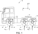
- the invention will be described below for a vehicle in the form of a truck 10 such as the truck illustrated in Fig. 1 .
- the truck 10 should be seen as an example of a vehicle which could comprise a control unit according to the present invention of for which the method of the present invention could be carried out.
- the present invention may be implemented in a plurality of different types of vehicles. Purely by way of example, the present invention could be implemented in a truck, a tractor, a car, a bus, a work machine such as a wheel loader or any other type of construction equipment.
- the Fig. 1 vehicle 10 comprises a set of ground engaging members.
- the ground engaging members are constituted by a set of wheels 12, 14, 16 each one of which being adapted to be supported by a ground segment 18.
- the Fig. 1 embodiment of the vehicle 10 comprises a pair of front wheels 12 and two pairs of rear wheels 14, 16, it is of course envisaged that other embodiments of the vehicle 10 may comprise fewer or more wheels.
- other embodiments of the vehicle 10 may comprise other types of ground engaging members, such as crawlers (not shown).
- the Fig. 1 embodiment of the vehicle comprises a wheel suspension system 20 connecting the wheels 12, 14, 16 to a vehicle frame 22 of the vehicle 10.
- the wheel suspension system 20 comprises a front wheel suspension system 24 connecting the vehicle frame 22 to the front wheel 12, a first rear wheel suspension system 26 connecting the vehicle frame 22 to the first rear wheel 14 and a second rear wheel suspension system 28 connecting the vehicle frame 22 to the second rear wheel 16.
- the front wheel suspension system 24 may comprise a flexible bellow 30 into which gas can be added or drained.
- each one of the first and second rear wheel suspension systems 26, 28 may comprise a flexible bellow 32, 34 into which gas can be added or drained.
- the wheel suspension system 20 is arranged to damp/absorb loads from the respective wheel during motion of the vehicle 10.
- the wheel suspension system 20 can be used for controlling the contact force between the associated wheel 12, 14, 16 and the ground segment 18.
- a reference to the front wheel 12 is equally applicable to the pair of front wheels.
- a reference to the first rear wheel 14 is equally applicable to the pair of first rear wheels and a reference to the second rear wheel 16 is equally applicable to the pair of second rear wheels.
- Fig. 1 indicates that the vehicle extends in a longitudinal direction along a longitudinal axis L as well as in a vertical direction along a vertical axis V.
- the longitudinal axis L extends in a direction parallel to the intended direction of travel of the vehicle 10 and the vertical axis V extends in a direction being normal to the plane of the ground segment 18.
- Fig. 1 further illustrates that a transversal axis T extends perpendicular to each one of the longitudinal and vertical axes L, V.
- the Fig. 1 vehicle 10 comprises a control unit 36 for determining a parameter indicative of a road capability of a road segment supporting a vehicle.
- Fig. 1 illustrates an embodiment in which the control unit 36 is physically connected to the vehicle 10, e.g. located in the vehicle 10 as illustrated in Fig. 1
- the control unit 36 according to the second aspect of the present invention need not necessarily be physically connected to the vehicle 10.
- embodiments of the control unit 36 are contemplated in which the control unit 36 is separate from the vehicle 10 and adapted to communicate with the vehicle 10 using e.g. a wireless communication system (not shown).
- the control unit 36 is suitable for determining a parameter indicative of a road capability of a road segment supporting a vehicle.
- An embodiment of the control unit 36 and its function will be presented hereinbelow with reference to Fig. 2 schematically illustrating a top view of a vehicle 10 comprising six ground engaging members 12, 14, 16, 38, 40, 42 each one of which being exemplified as a wheel.
- embodiments of the control unit 36 may be adapted to control vehicles having fewer or more ground engaging members than the Fig. 2 number of six.
- the control unit 36 is adapted to set a contact force between the ground engaging member and the road segment for each ground engaging member in a sub-set of the plurality of ground engaging members.
- the sub-set comprises two wheels, viz the first rear wheel 14 on the left hand side and the second rear wheel 42 on the right hand side of the vehicle 10.
- the term contact force may be constituted by a normal force only between the ground engaging member and the road segment, for instance in a situation when the vehicle 10 is located on a flat surface.
- the contact force may be the resulting force from the normal force and a frictional force, such as a static frictional force.
- the normal force as well as the frictional force may form the contact force.
- a dynamic frictional force may be included in the contact force. For instance, if a certain torque change is to be imparted to a ground engaging member, for instance in order to determine a friction value, an expected frictional force may be determined on the basis of the torque change and such a frictional force may form part of the contact force to be set for that ground engaging member.
- the vehicle 10 has a longitudinal centre plane, formed by the longitudinal axis L and the vertical axis V in Fig. 2 , separating the vehicle 10 into a first i. and a second ii. longitudinal half.
- a first ground engaging member 14 in the sub-set may preferably be located in the first longitudinal half i.
- a second ground engaging member 42 in the sub-set may preferably be located in the second longitudinal half ii.
- Such a selection of the ground engaging members may in particular be preferred when the vehicle 10 comprises six ground engaging members or more since the contact force control of at least one ground engaging member on either side of the longitudinal halves can be obtained without resulting in an undesirably low stability of the vehicle 10.
- the contact force between the left first rear wheel 14 and the road segment 18, which contact force in the Fig. 2 situation is constituted by a normal force imparted to the left first rear wheel 14, is set to a certain value N 14,S .
- the value of the contact force here exemplified as the value of the normal force, may be dependent on the type of road capability for which a parameter is to be determined. For instance, in the even that a friction value is to be determined, the value N 14,S may be set so as to be relatively low. On the other hand, in the even that a load bearing capability is to be determined, the value N 14,S may be set so as to be relatively high.
- the contact force between the right second rear wheel 42 and the road segment 18, which contact force in the Fig. 2 situation is constituted by a normal force imparted to the right second rear wheel 42, is set to a certain value N 42,S .
- the subscript S indicates that a contact force that is set.
- the values to which the contact force may be set for each ground engaging member in a sub-set of the plurality of ground engaging members may be determined in a plurality of ways.
- the contact force values may be predetermined.
- the contact force values may be determined on the basis of the weight of the vehicle. For instance, the contact force values may set so as to be predetermined fractions of the weight of the vehicle 10.
- control unit 36 is adapted to determine a target global load vector G to be imparted to the vehicle 10.
- the target global load vector G comprises at least a vertical load F V and an inclining moment M.
- the vertical load F VG relates to a load out of the Fig. 2 plane, viz in a direction along the vertical axis V.
- the roll inclining moment M LG relates to a moment around the longitudinal axis L and the pitch inclining moment M TG relates to a moment around the transversal axis T.
- the control unit 36 is adapted to determine contact forces N 12 , N 16 , N 38 , N 40 for the ground engaging members of the plurality of ground engaging members which are not in the sub-set such that the contact forces for the plurality of ground engaging members together result in a resulting global load vector R.
- the contact forces N 12 , N 16 , N 38 , N 40 are exemplified as normal forces.
- a difference measure DM between the resulting global load vector R and the target global load vector G is equal to or lower than a predetermined difference measure threshold.
- An example of the resulting global load vector R is presented in Eq. 2 hereinbelow.
- R F VR M LR M TR .
- Eq. 3 is based on the assumption that the contact forces N 12 , N 14,S , N 16 , N 38 , N 40 , N 42,S are constituted by normal forces.
- the present description and for instance Eq. 3 can be expanded so as to cover contact forces that comprise a normal force component and a frictional force component.
- a non-limiting example is presented hereinbelow with reference to Eq. 7.
- the difference measure DM between the resulting global load vector R and the target global load vector G may be determined by calculating the Euclidian norm between the two vectors.
- control unit 36 may be adapted to determine values of the contact forces N 12 , N 16 , N 38 , N 40 for the ground engaging members of the plurality of ground engaging members which are not in the sub-set such that the difference measure DM is equal to or lower than a predetermined difference measure threshold.
- control unit 36 may be adapted to employ an iterative process in order to determine values of the contact forces N 12 , N 16 , N 38 , N 40 .
- an iterative process may comprise constraints in terms of predetermined minimum and maximum values for each one of the contact forces N 12 , N 16 , N 38 , N 40 .
- control unit 36 may be adapted to solve Eq. 5 using an iterative process in order to determine values of the contact forces N 12 , N 16 , N 38 , N 40 .
- an iterative process may comprise constraints in terms of predetermined minimum and maximum values for each one of the contact forces N 12 , N 16 , N 38 , N 40 .
- the control unit 36 uses Eq. 1 - Eq. 4 or Eq. 5 hereinabove, the relation between the number of unknown parameters - i.e. the contact forces N 12 , N 16 , N 38 , N 40 in the above example - and the number of rows of the equation system will determine whether a single or a plurality of possible solutions exist.
- control unit 36 is adapted to determine the contact forces N 12 , N 16 , N 38 , N 40 for the ground engaging members of the plurality of ground engaging members which are not in the sub-set, the control unit 36 is adapted to issue information to the suspension system 20 to impart the contact force N 12 , N 14,S , N 16 , N 38 , N 40 , N 42,S to each ground engaging member 12, 14, 16, 38, 40, 42 of the plurality of ground engaging members.
- control unit 36 may be adapted to issue information to the suspension system to apply the contact force N 12 , N 14.3 , N 16 , N 38 , N 40 , N 42,S to each ground engaging member 12, 14, 16, 38, 40, 42 of the plurality of ground engaging members using a ramp function.
- the ramp function may be a linear ramp function changing a contact force from an initial contact force to the desired contact force during a predetermined ramp time.
- control unit 36 is adapted to determine a parameter indicative of the road capability of the road segment associated with the ground engaging member for at least one ground engaging member 14, 42 in the sub-set.
- the parameter indicative of the road capability of the road segment associated with the ground engaging member can be a friction value ⁇ between the ground engaging member 14, 42 and the road segment 18.
- the control unit 36 may be adapted to determine the friction value ⁇ between the ground engaging member and the road segment by issuing a signal to impart a torque to the ground engaging member 14, 42.
- the signal to impart a torque to the ground engaging member 14, 42 may be a signal to increase or decrease the torque imparted to the ground engaging member 14, 42, as compared to the torque imparted to the ground engaging member 14, 42 before commencing the friction value ⁇ determination.
- the torque can be selected such that the rotational speed of the ground engaging member 14 is lower than what would be expected in view of the current speed of the vehicle 10.
- the control unit 36 may be adapted issue a signal to impart a torque to the ground engaging member using the ramp function discussed hereinabove.
- the parameter indicative of the road capability of the road segment associated with the ground engaging member is a load bearing capability value indicative of the load bearing capability of the ground segment 18 supporting the vehicle 10.
- the ground engaging member 14 as an example, in a situation in which the value N 14,S is set so as to be relatively high, the vertical depression of the ground engaging member 14 into the ground segment 18 can be determined such that a stiffness of the ground segment 18 can be determined.
- the target global load vector G may be determined in a plurality of ways. Purely by way of example, the target global load vector G may be determined such that a desired condition of the vehicle 10, for instance in terms of a desired roll and/or pitch, is obtained. As another non-limiting example, the target global load vector G may be selected such that a required stability of the vehicle 10 is obtained. Purely by way of example, the required stability may be determined taking a stability influence into account, which stability influence emanates from the procedure of determining the parameter indicative of the road capability of the road segment associated with the ground engaging member.
- the target global load vector G may be determined by by determining an initial global load vector I imparted to the vehicle before the contact force is applied to each ground engaging member of the plurality of ground engaging members.
- the control unit 36 may be adapted to set the target global load vector G equal to the initial global load vector I.
- the invention also relates to a method for determining a parameter indicative of a road capability of a road segment 18 supporting a vehicle 10.
- the vehicle 10 comprises a plurality of ground engaging members 12, 14, 16, 38, 40, 42.
- a flow chart of an embodiment of the method according to the present invention is presented on Fig. 3 .
- the method embodiment comprises: S10 for each ground engaging member 14, 42 in a sub-set of the plurality of ground engaging members, setting a contact force N 14,S , N 42,S between the ground engaging member 14, 42 and the road segment 18; S12 determining a target global load vector G to be imparted to the vehicle 10, the target global load vector G comprising at least a vertical load and an inclining moment, S14 determining contact forces N 12 , N 16 , N 38 , N 40 for the ground engaging members 12, 16, 38, 40 of the plurality of ground engaging members which are not in the sub-set such that the contact forces N 12 , N 14 , N 16 , N 38 , N 40 , N 42 for the plurality of ground engaging members together result in a resulting global load vector R, a difference measure DM between the resulting global load vector R and the target global load vector G being equal to or lower than a predetermined difference measure threshold , S16 applying the contact force to each ground engaging member of the plurality of ground engaging members,
- the above method may for instance be carried out using the control unit 36 discussed hereinabove. However, it is also envisaged that the method according to the present invention may be carried out using other means.
- the above method feature S16 of applying the contact forces may be achieved using a vehicle suspension system, such as the Fig. 1 vehicle suspension system 20. However, it is also contemplated that embodiments of the method may employ other means for applying the contact forces.
- the contact force to be set for the left first rear wheel 14 in Fig. 2 comprises the normal force N 14,S as well as a frictional force F L14,S in the direction of the longitudinal axis L, Eq.
- Eq. 7 can be expanded further by for instance adding a frictional force F T14,S in the direction of the transversal axis T to the contact force of the left first rear wheel 14 in Fig. 2 and/or by for example adding horizontal force components to any one of the other ground engaging members.
Landscapes
- Engineering & Computer Science (AREA)
- Mechanical Engineering (AREA)
- Automation & Control Theory (AREA)
- Transportation (AREA)
- Physics & Mathematics (AREA)
- Mathematical Physics (AREA)
- Chemical & Material Sciences (AREA)
- Combustion & Propulsion (AREA)
- Vehicle Body Suspensions (AREA)
- Control Of Driving Devices And Active Controlling Of Vehicle (AREA)
Claims (15)
- Procédé permettant de déterminer un paramètre indiquant une aptitude routière d'un segment routier (18) supportant un véhicule (10), ledit véhicule (10) comprenant une pluralité d'éléments de prise au sol (12, 14, 16, 38, 40, 42), ledit procédé comprenant :- pour chaque élément de prise au sol (14, 42) dans un sous-ensemble de ladite pluralité d'éléments de prise au sol (12, 14, 16, 38, 40, 42), le réglage d'une force de contact (N14,S, N42,S) entre ledit élément de prise au sol (12, 14, 16, 38, 40, 42) et ledit segment routier (18) ;- la détermination d'un vecteur de charge globale cible (G) à conférer audit véhicule (10), ledit vecteur de charge globale cible (G) comprenant au moins une charge verticale et un moment d'inclinaison,- la détermination de forces de contact (N12, N16, N38, N40) pour les éléments de prise au sol (12, 16, 38, 40) de ladite pluralité d'éléments de prise au sol (12, 14, 16, 38, 40, 42) qui ne sont pas dans ledit sous-ensemble de sorte que les forces de contact (N12, N14,S, N16, N38, N40, N42,S) pour ladite pluralité d'éléments de prise au sol (12, 14, 16, 38, 40, 42) résultent ensemble en un vecteur de charge globale résultant (R), une mesure de différence (DM) entre ledit vecteur de charge globale résultant (R) et ledit vecteur de charge globale cible (G) étant égale ou inférieure à un seuil de mesure de différence prédéterminé,- l'application de ladite force de contact (N12, N14,S, N16, N38, N40, N42,S) à chaque élément de prise au sol de ladite pluralité d'éléments de prise au sol (12, 14, 16, 38, 40, 42),- pour au moins un élément de prise au sol (14, 42) dans ledit sous-ensemble, la détermination d'un paramètre indiquant l'aptitude routière du segment routier (18) associé à l'élément de prise au sol (14, 42).
- Procédé selon la revendication 1, dans lequel la détermination dudit vecteur de charge globale cible (G) comprend la détermination d'un vecteur de charge globale initial (I) conféré audit véhicule (10) avant que ladite force de contact ne soit appliquée à chaque élément de prise au sol (12, 14, 16, 38, 40, 42) de ladite pluralité d'éléments de prise au sol (12, 14, 16, 38, 40, 42), de préférence ledit procédé comprend le réglage dudit vecteur de charge globale cible (G) égal audit vecteur de charge globale initial (I).
- Procédé selon l'une quelconque des revendications précédentes, dans lequel ledit véhicule (10) a un plan central longitudinal séparant ledit véhicule (10) en une première et une seconde moitié longitudinale (i., ii.), un premier élément de prise au sol (14) dans ledit sous-ensemble étant localisé dans ladite première moitié longitudinale (i.) et un second élément de prise au sol (42) dans ledit sous-ensemble étant localisé dans ladite seconde moitié longitudinale (ii.).
- Procédé selon l'une quelconque des revendications précédentes, dans lequel ladite pluralité d'éléments de prise au sol (12, 14, 16, 38, 40, 42) comprend une ou plusieurs roues, de préférence chaque élément de prise au sol (12, 14, 16, 38, 40, 42) de ladite pluralité d'éléments de prise au sol (12, 14, 16, 38, 40, 42) étant constitué d'une roue, de préférence ledit paramètre indiquant l'aptitude routière du segment routier (18) associé à l'élément de prise au sol (14, 42) est une valeur de frottement (µ) entre ledit élément de prise au sol (14, 42) et ledit segment routier (18), de préférence la détermination de ladite valeur de frottement (µ) entre ledit élément de prise au sol (14, 42) et ledit segment routier (18) comprend le fait de conférer un couple audit élément de prise au sol.
- Procédé selon l'une quelconque des revendications précédentes, dans lequel ledit paramètre indiquant l'aptitude routière du segment routier (18) associé à l'élément de prise au sol (14, 42) est une valeur d'aptitude au support de charge indiquant l'aptitude au support de charge dudit segment de sol supportant ledit véhicule (10).
- Procédé selon l'une quelconque des revendications précédentes, dans lequel ledit véhicule (10) comprend un châssis de véhicule (22) et un système de suspension (20) reliant la pluralité d'éléments de prise au sol (12, 14, 16, 38, 40, 42) audit châssis de véhicule (22), ladite caractéristique d'application de ladite force de contact à chaque élément de prise au sol (12, 14, 16, 38, 40, 42) de ladite pluralité d'éléments de prise au sol (12, 14, 16, 38, 40, 42) comprenant le fonctionnement dudit système de suspension (20).
- Procédé selon l'une quelconque des revendications précédentes, dans lequel chaque force de contact (N12, N14,S, N16, N38, N40, N42,S) comprend une force normale conférée à l'élément de prise au sol connexe (12, 14, 16, 38, 40, 42), de préférence au moins une force de contact (N12, N14,S, N16, N38, N40, N42,S) comprend la force normale et une force de frottement conférée à l'élément de prise au sol connexe (12, 14, 16, 38, 40, 42).
- Unité de commande (36) permettant de déterminer un paramètre indiquant une aptitude routière d'un segment routier (18) supportant un véhicule (10), ledit véhicule (10) comprenant un châssis de véhicule (22), une pluralité d'éléments de prise au sol (12, 14, 16, 38, 40, 42) et un système de suspension (20) reliant la pluralité d'éléments de prise au sol (12, 14, 16, 38, 40, 42) audit châssis de véhicule (22), ladite unité de commande (36) étant conçue pour :- pour chaque élément de prise au sol (14, 42) dans un sous-ensemble de ladite pluralité d'éléments de prise au sol (12, 14, 16, 38, 40, 42), régler une force de contact (N14,S, N42,S) entre ledit élément de prise au sol (14, 42) et ledit segment routier (18) ;- déterminer un vecteur de charge globale cible (G) à conférer audit véhicule (10), ledit vecteur de charge globale cible (G) comprenant au moins une charge verticale et un moment d'inclinaison,- déterminer des forces de contact (N12, N16, N38, N40) pour les éléments de prise au sol (12, 14, 16, 38, 40, 42) de ladite pluralité d'éléments de prise au sol (12, 14, 16, 38, 40, 42) qui ne sont pas dans ledit sous-ensemble de sorte que les forces de contact pour ladite pluralité d'éléments de prise au sol (12, 14, 16, 38, 40, 42) résultent ensemble en un vecteur de charge globale résultant (R), une mesure de différence (DM) entre ledit vecteur de charge globale résultant (R) et ledit vecteur de charge globale cible (G) étant égale ou inférieure à un seuil de mesure de différence prédéterminé,- délivrer des informations audit système de suspension (20) pour conférer ladite force de contact (N12, N14,S, N16, N38, N40, N42,S) à chaque élément de prise au sol (12, 14, 16, 38, 40, 42) de ladite pluralité d'éléments de prise au sol (12, 14, 16, 38, 40, 42),- pour au moins un élément de prise au sol (14, 42) dans ledit sous-ensemble, déterminer un paramètre indiquant l'aptitude routière du segment routier (18) associé à l'élément de prise au sol (14, 42).
- Unité de commande (36) selon la revendication 8, dans laquelle ladite unité de commande (36) est conçue pour déterminer ledit vecteur de charge globale cible (G) en déterminant un vecteur de charge globale initial (I) conféré audit véhicule (10) avant que ladite force de contact ne soit appliquée à chaque élément de prise au sol (12, 14, 16, 38, 40, 42) de ladite pluralité d'éléments de prise au sol (12, 14, 16, 38, 40, 42), de préférence ladite unité de commande (36) est conçue pour régler ledit vecteur de charge globale cible (G) égal audit vecteur de charge globale initial (I).
- Unité de commande (36) selon la revendication 8 ou 9, dans laquelle ledit véhicule (10) a un plan central longitudinal séparant ledit véhicule (10) en une première et une seconde moitié longitudinale (i., ii.), un premier élément de prise au sol (12, 14, 16, 38, 40, 42) dans ledit sous-ensemble étant localisé dans ladite première moitié longitudinale (i.) et un second élément de prise au sol (12, 14, 16, 38, 40, 42) dans ledit sous-ensemble étant localisé dans ladite seconde moitié longitudinale (ii.).
- Unité de commande (36) selon l'une quelconque des revendications 8 à 10, dans laquelle ladite unité de commande (36) est conçue pour délivrer des informations audit système de suspension (20) pour appliquer ladite force de contact à chaque élément de prise au sol (12, 14, 16, 38, 40, 42) de ladite pluralité d'éléments de prise au sol (12, 14, 16, 38, 40, 42) à l'aide d'une fonction de rampe.
- Unité de commande (36) selon l'une quelconque des revendications 8 à 11, dans laquelle ledit paramètre indiquant l'aptitude routière du segment routier (18) associé à l'élément de prise au sol (14, 42) est une valeur de frottement (µ) entre ledit élément de prise au sol (14, 42) et ledit segment routier (18), de préférence ladite unité de commande (36) est conçue pour déterminer ladite valeur de frottement (µ) entre ledit élément de prise au sol (14, 42) et ledit segment routier (18) en délivrant un signal pour conférer un couple audit élément de prise au sol (14, 42).
- Unité de commande (36) selon l'une quelconque des revendications 8 à 12, dans laquelle ledit paramètre indiquant l'aptitude routière du segment routier (18) associé à l'élément de prise au sol (12, 14, 16, 38, 40, 42) est une valeur d'aptitude au support de charge indiquant l'aptitude au support de charge dudit segment de sol supportant ledit véhicule (10).
- Unité de commande (36) selon l'une quelconque des revendications 8 à 13, dans laquelle chaque force de contact (N12, N14,S, N16, N38, N40, N42,S) comprend une force normale conférée à l'élément de prise au sol connexe (12, 14, 16, 38, 40, 42), de préférence au moins une force de contact (N12, N14,S, N16, N38, N40, N42,S) comprend la force normale et une force de frottement conférée à l'élément de prise au sol connexe (12, 14, 16, 38, 40, 42).
- Véhicule (10) comprenant une unité de commande (36) selon l'une quelconque des revendications 8 à 14, de préférence ladite pluralité d'éléments de prise au sol (12, 14, 16, 38, 40, 42) comprend une ou plusieurs roues, de préférence chaque élément de prise au sol (12, 14, 16, 38, 40, 42) de ladite pluralité d'éléments de prise au sol (12, 14, 16, 38, 40, 42) étant constitué d'une roue.
Applications Claiming Priority (1)
| Application Number | Priority Date | Filing Date | Title |
|---|---|---|---|
| PCT/EP2019/058714 WO2020200484A1 (fr) | 2019-04-05 | 2019-04-05 | Procédé et unité de commande pour déterminer un paramètre indiquant la capacité de route d'un segment de route supportant un véhicule |
Publications (3)
| Publication Number | Publication Date |
|---|---|
| EP3947085A1 EP3947085A1 (fr) | 2022-02-09 |
| EP3947085B1 true EP3947085B1 (fr) | 2024-03-13 |
| EP3947085C0 EP3947085C0 (fr) | 2024-03-13 |
Family
ID=66218056
Family Applications (1)
| Application Number | Title | Priority Date | Filing Date |
|---|---|---|---|
| EP19718089.6A Active EP3947085B1 (fr) | 2019-04-05 | 2019-04-05 | Procédé et unité de commande pour déterminer un paramètre indiquant la capacité de route d'un segment de route supportant un véhicule |
Country Status (6)
| Country | Link |
|---|---|
| US (1) | US11970039B2 (fr) |
| EP (1) | EP3947085B1 (fr) |
| JP (1) | JP7368491B2 (fr) |
| KR (1) | KR102577429B1 (fr) |
| CN (1) | CN113661108B (fr) |
| WO (1) | WO2020200484A1 (fr) |
Families Citing this family (3)
| Publication number | Priority date | Publication date | Assignee | Title |
|---|---|---|---|---|
| DE102020111915B3 (de) * | 2020-05-04 | 2021-06-24 | Dr. Ing. H.C. F. Porsche Aktiengesellschaft | Verfahren zur Ermittlung von Fahrzeugkenngrößen |
| GB2601356B (en) * | 2020-11-27 | 2023-10-04 | Jaguar Land Rover Ltd | Traction determination by changing wheel normal force |
| KR20250028716A (ko) | 2023-08-22 | 2025-03-04 | 주식회사 범영코리아 | 분리 대두 단백의 제조방법 및 이를 이용하여 제조된 단백질 식품 |
Family Cites Families (20)
| Publication number | Priority date | Publication date | Assignee | Title |
|---|---|---|---|---|
| JPH0741783B2 (ja) * | 1986-05-23 | 1995-05-10 | 日産自動車株式会社 | サスペンシヨン制御装置 |
| US5028073A (en) | 1990-01-08 | 1991-07-02 | General Electric Company | Dynamic vehicle suspension system including electronically commutated motor |
| US20040046335A1 (en) | 2000-03-27 | 2004-03-11 | Knox Lawrence D. | Surface vehicle vertical trajectory planning |
| JP4501343B2 (ja) * | 2002-12-17 | 2010-07-14 | トヨタ自動車株式会社 | 車輌用制動力制御装置 |
| JP4193706B2 (ja) | 2004-01-23 | 2008-12-10 | トヨタ自動車株式会社 | 路面摩擦係数検出装置 |
| DE102004010548B4 (de) * | 2004-03-04 | 2022-09-08 | Zf Cv Systems Hannover Gmbh | Fahrzeug-Anfahrhilfe |
| DE102007007282A1 (de) * | 2006-02-21 | 2007-09-06 | Continental Teves Ag & Co. Ohg | Verfahren zum Schätzen von Reibwerten |
| DE102006017823A1 (de) * | 2006-04-13 | 2007-10-18 | Daimlerchrysler Ag | System zur Beeinflussung des Fahrverhaltens eines Fahrzeuges |
| JP2008285006A (ja) | 2007-05-17 | 2008-11-27 | Advics:Kk | 車両駆動輪荷重制御装置 |
| US8751091B2 (en) * | 2008-03-13 | 2014-06-10 | Koninklijke Philips N.V. | Sensor system, vehicle control system and driver information system for vehicle safety |
| DE102008024093A1 (de) * | 2008-05-17 | 2009-11-19 | Bayerische Motoren Werke Aktiengesellschaft | Verfahren zum Bestimmen radindividueller Reibwerte |
| CN102387947A (zh) * | 2009-04-10 | 2012-03-21 | 丰田自动车株式会社 | 车辆的重量关联物理量推断装置以及控制装置 |
| US10524542B2 (en) * | 2013-11-22 | 2020-01-07 | Nike, Inc. | Sole structure with side stiffener for article of footwear |
| KR101582572B1 (ko) | 2013-12-24 | 2016-01-11 | 엘지전자 주식회사 | 차량 운전 보조 장치 및 이를 구비한 차량 |
| CA3014660C (fr) | 2016-02-15 | 2021-08-17 | Allstate Insurance Company | Avis rapide de zone non autonome |
| DE102016212587A1 (de) | 2016-07-11 | 2018-01-11 | Continental Automotive Gmbh | Verfahren und System zur Erzeugung von Karteninformationen |
| KR101864066B1 (ko) * | 2017-01-11 | 2018-07-05 | 숭실대학교산학협력단 | 차선 인식 장치, 차선 이탈 판단 장치, 차선 인식 방법 및 차선 이탈 판단 방법 |
| BE1025282B1 (nl) | 2017-06-02 | 2019-01-11 | Cnh Industrial Belgium Nv | Draagvermogen van de grond |
| JP6572264B2 (ja) | 2017-06-28 | 2019-09-04 | 株式会社Subaru | 車両の路面摩擦係数推定装置及び車両の路面摩擦係数推定方法 |
| US10988142B1 (en) * | 2017-09-27 | 2021-04-27 | Apple Inc. | Determining friction coefficient of a tire/surface interface |
-
2019
- 2019-04-05 EP EP19718089.6A patent/EP3947085B1/fr active Active
- 2019-04-05 KR KR1020217032895A patent/KR102577429B1/ko active Active
- 2019-04-05 CN CN201980095145.5A patent/CN113661108B/zh not_active Expired - Fee Related
- 2019-04-05 WO PCT/EP2019/058714 patent/WO2020200484A1/fr not_active Ceased
- 2019-04-05 JP JP2021559293A patent/JP7368491B2/ja active Active
- 2019-04-05 US US17/594,157 patent/US11970039B2/en active Active
Also Published As
| Publication number | Publication date |
|---|---|
| CN113661108A (zh) | 2021-11-16 |
| JP2022534839A (ja) | 2022-08-04 |
| EP3947085C0 (fr) | 2024-03-13 |
| KR20210145169A (ko) | 2021-12-01 |
| US20220161627A1 (en) | 2022-05-26 |
| US11970039B2 (en) | 2024-04-30 |
| JP7368491B2 (ja) | 2023-10-24 |
| KR102577429B1 (ko) | 2023-09-13 |
| CN113661108B (zh) | 2024-07-05 |
| WO2020200484A1 (fr) | 2020-10-08 |
| EP3947085A1 (fr) | 2022-02-09 |
Similar Documents
| Publication | Publication Date | Title |
|---|---|---|
| US11639178B2 (en) | Vehicle control method and device | |
| US8219282B2 (en) | System for dynamically determining vehicle rear/trunk loading for use in a vehicle control system | |
| US8718872B2 (en) | Vehicle attitude controller | |
| US7877199B2 (en) | System and method for dynamically determining vehicle loading and vertical loading distance for use in a vehicle dynamic control system | |
| US20050131604A1 (en) | Roll stability control system for an automotive vehicle using coordinated control of anti-roll bar and brakes | |
| EP3947085B1 (fr) | Procédé et unité de commande pour déterminer un paramètre indiquant la capacité de route d'un segment de route supportant un véhicule | |
| US20050182548A1 (en) | Method and device for detecting parameters characterizing the driving behavior of a vehicle | |
| EP4206005B1 (fr) | Procédé de commande de suspension et véhicule | |
| US8209067B2 (en) | Height control device for vehicle | |
| US7797093B2 (en) | Wheel ground-contact state judging device and method | |
| US12528452B2 (en) | Vehicle dynamics system adjustment | |
| US20220332329A1 (en) | Vehicle control apparatus | |
| US11712939B2 (en) | Vehicle and method of controlling vehicle suspension | |
| US11325599B2 (en) | Vehicle control system for adjusting longtitudinal motion to reduce deviation of lateral motion | |
| US11148498B2 (en) | Method for controlling wheel axle suspension of a vehicle | |
| US11738616B2 (en) | Vehicle handling | |
| CN112590771B (zh) | 车辆稳定控制方法及系统 | |
| JP3814057B2 (ja) | 接地荷重制御装置 | |
| SE539434C2 (en) | Method and system for facilitating steering of a vehicle while driving along a road | |
| JP2008247066A (ja) | 車両の運動制御装置 | |
| JPH0584508U (ja) | 車両用サスペンション制御装置 |
Legal Events
| Date | Code | Title | Description |
|---|---|---|---|
| STAA | Information on the status of an ep patent application or granted ep patent |
Free format text: STATUS: UNKNOWN |
|
| STAA | Information on the status of an ep patent application or granted ep patent |
Free format text: STATUS: THE INTERNATIONAL PUBLICATION HAS BEEN MADE |
|
| PUAI | Public reference made under article 153(3) epc to a published international application that has entered the european phase |
Free format text: ORIGINAL CODE: 0009012 |
|
| STAA | Information on the status of an ep patent application or granted ep patent |
Free format text: STATUS: REQUEST FOR EXAMINATION WAS MADE |
|
| 17P | Request for examination filed |
Effective date: 20211102 |
|
| AK | Designated contracting states |
Kind code of ref document: A1 Designated state(s): AL AT BE BG CH CY CZ DE DK EE ES FI FR GB GR HR HU IE IS IT LI LT LU LV MC MK MT NL NO PL PT RO RS SE SI SK SM TR |
|
| DAV | Request for validation of the european patent (deleted) | ||
| DAX | Request for extension of the european patent (deleted) | ||
| GRAP | Despatch of communication of intention to grant a patent |
Free format text: ORIGINAL CODE: EPIDOSNIGR1 |
|
| STAA | Information on the status of an ep patent application or granted ep patent |
Free format text: STATUS: GRANT OF PATENT IS INTENDED |
|
| INTG | Intention to grant announced |
Effective date: 20231016 |
|
| GRAS | Grant fee paid |
Free format text: ORIGINAL CODE: EPIDOSNIGR3 |
|
| GRAA | (expected) grant |
Free format text: ORIGINAL CODE: 0009210 |
|
| STAA | Information on the status of an ep patent application or granted ep patent |
Free format text: STATUS: THE PATENT HAS BEEN GRANTED |
|
| AK | Designated contracting states |
Kind code of ref document: B1 Designated state(s): AL AT BE BG CH CY CZ DE DK EE ES FI FR GB GR HR HU IE IS IT LI LT LU LV MC MK MT NL NO PL PT RO RS SE SI SK SM TR |
|
| REG | Reference to a national code |
Ref country code: GB Ref legal event code: FG4D |
|
| REG | Reference to a national code |
Ref country code: CH Ref legal event code: EP |
|
| REG | Reference to a national code |
Ref country code: DE Ref legal event code: R096 Ref document number: 602019048180 Country of ref document: DE |
|
| REG | Reference to a national code |
Ref country code: IE Ref legal event code: FG4D |
|
| U01 | Request for unitary effect filed |
Effective date: 20240408 |
|
| U07 | Unitary effect registered |
Designated state(s): AT BE BG DE DK EE FI FR IT LT LU LV MT NL PT SE SI Effective date: 20240416 |
|
| PG25 | Lapsed in a contracting state [announced via postgrant information from national office to epo] |
Ref country code: GR Free format text: LAPSE BECAUSE OF FAILURE TO SUBMIT A TRANSLATION OF THE DESCRIPTION OR TO PAY THE FEE WITHIN THE PRESCRIBED TIME-LIMIT Effective date: 20240614 |
|
| PG25 | Lapsed in a contracting state [announced via postgrant information from national office to epo] |
Ref country code: HR Free format text: LAPSE BECAUSE OF FAILURE TO SUBMIT A TRANSLATION OF THE DESCRIPTION OR TO PAY THE FEE WITHIN THE PRESCRIBED TIME-LIMIT Effective date: 20240313 Ref country code: RS Free format text: LAPSE BECAUSE OF FAILURE TO SUBMIT A TRANSLATION OF THE DESCRIPTION OR TO PAY THE FEE WITHIN THE PRESCRIBED TIME-LIMIT Effective date: 20240613 |
|
| PG25 | Lapsed in a contracting state [announced via postgrant information from national office to epo] |
Ref country code: ES Free format text: LAPSE BECAUSE OF FAILURE TO SUBMIT A TRANSLATION OF THE DESCRIPTION OR TO PAY THE FEE WITHIN THE PRESCRIBED TIME-LIMIT Effective date: 20240313 |
|
| PG25 | Lapsed in a contracting state [announced via postgrant information from national office to epo] |
Ref country code: RS Free format text: LAPSE BECAUSE OF FAILURE TO SUBMIT A TRANSLATION OF THE DESCRIPTION OR TO PAY THE FEE WITHIN THE PRESCRIBED TIME-LIMIT Effective date: 20240613 Ref country code: NO Free format text: LAPSE BECAUSE OF FAILURE TO SUBMIT A TRANSLATION OF THE DESCRIPTION OR TO PAY THE FEE WITHIN THE PRESCRIBED TIME-LIMIT Effective date: 20240613 Ref country code: HR Free format text: LAPSE BECAUSE OF FAILURE TO SUBMIT A TRANSLATION OF THE DESCRIPTION OR TO PAY THE FEE WITHIN THE PRESCRIBED TIME-LIMIT Effective date: 20240313 Ref country code: GR Free format text: LAPSE BECAUSE OF FAILURE TO SUBMIT A TRANSLATION OF THE DESCRIPTION OR TO PAY THE FEE WITHIN THE PRESCRIBED TIME-LIMIT Effective date: 20240614 Ref country code: ES Free format text: LAPSE BECAUSE OF FAILURE TO SUBMIT A TRANSLATION OF THE DESCRIPTION OR TO PAY THE FEE WITHIN THE PRESCRIBED TIME-LIMIT Effective date: 20240313 |
|
| U20 | Renewal fee for the european patent with unitary effect paid |
Year of fee payment: 6 Effective date: 20240624 |
|
| PG25 | Lapsed in a contracting state [announced via postgrant information from national office to epo] |
Ref country code: IS Free format text: LAPSE BECAUSE OF FAILURE TO SUBMIT A TRANSLATION OF THE DESCRIPTION OR TO PAY THE FEE WITHIN THE PRESCRIBED TIME-LIMIT Effective date: 20240713 |
|
| PG25 | Lapsed in a contracting state [announced via postgrant information from national office to epo] |
Ref country code: SM Free format text: LAPSE BECAUSE OF FAILURE TO SUBMIT A TRANSLATION OF THE DESCRIPTION OR TO PAY THE FEE WITHIN THE PRESCRIBED TIME-LIMIT Effective date: 20240313 |
|
| PG25 | Lapsed in a contracting state [announced via postgrant information from national office to epo] |
Ref country code: CZ Free format text: LAPSE BECAUSE OF FAILURE TO SUBMIT A TRANSLATION OF THE DESCRIPTION OR TO PAY THE FEE WITHIN THE PRESCRIBED TIME-LIMIT Effective date: 20240313 |
|
| PG25 | Lapsed in a contracting state [announced via postgrant information from national office to epo] |
Ref country code: PL Free format text: LAPSE BECAUSE OF FAILURE TO SUBMIT A TRANSLATION OF THE DESCRIPTION OR TO PAY THE FEE WITHIN THE PRESCRIBED TIME-LIMIT Effective date: 20240313 |
|
| PG25 | Lapsed in a contracting state [announced via postgrant information from national office to epo] |
Ref country code: SK Free format text: LAPSE BECAUSE OF FAILURE TO SUBMIT A TRANSLATION OF THE DESCRIPTION OR TO PAY THE FEE WITHIN THE PRESCRIBED TIME-LIMIT Effective date: 20240313 |
|
| PG25 | Lapsed in a contracting state [announced via postgrant information from national office to epo] |
Ref country code: SM Free format text: LAPSE BECAUSE OF FAILURE TO SUBMIT A TRANSLATION OF THE DESCRIPTION OR TO PAY THE FEE WITHIN THE PRESCRIBED TIME-LIMIT Effective date: 20240313 Ref country code: SK Free format text: LAPSE BECAUSE OF FAILURE TO SUBMIT A TRANSLATION OF THE DESCRIPTION OR TO PAY THE FEE WITHIN THE PRESCRIBED TIME-LIMIT Effective date: 20240313 Ref country code: RO Free format text: LAPSE BECAUSE OF FAILURE TO SUBMIT A TRANSLATION OF THE DESCRIPTION OR TO PAY THE FEE WITHIN THE PRESCRIBED TIME-LIMIT Effective date: 20240313 Ref country code: PL Free format text: LAPSE BECAUSE OF FAILURE TO SUBMIT A TRANSLATION OF THE DESCRIPTION OR TO PAY THE FEE WITHIN THE PRESCRIBED TIME-LIMIT Effective date: 20240313 Ref country code: IS Free format text: LAPSE BECAUSE OF FAILURE TO SUBMIT A TRANSLATION OF THE DESCRIPTION OR TO PAY THE FEE WITHIN THE PRESCRIBED TIME-LIMIT Effective date: 20240713 Ref country code: CZ Free format text: LAPSE BECAUSE OF FAILURE TO SUBMIT A TRANSLATION OF THE DESCRIPTION OR TO PAY THE FEE WITHIN THE PRESCRIBED TIME-LIMIT Effective date: 20240313 |
|
| REG | Reference to a national code |
Ref country code: CH Ref legal event code: PL |
|
| REG | Reference to a national code |
Ref country code: DE Ref legal event code: R097 Ref document number: 602019048180 Country of ref document: DE |
|
| PG25 | Lapsed in a contracting state [announced via postgrant information from national office to epo] |
Ref country code: MC Free format text: LAPSE BECAUSE OF FAILURE TO SUBMIT A TRANSLATION OF THE DESCRIPTION OR TO PAY THE FEE WITHIN THE PRESCRIBED TIME-LIMIT Effective date: 20240313 |
|
| PLBE | No opposition filed within time limit |
Free format text: ORIGINAL CODE: 0009261 |
|
| STAA | Information on the status of an ep patent application or granted ep patent |
Free format text: STATUS: NO OPPOSITION FILED WITHIN TIME LIMIT |
|
| PG25 | Lapsed in a contracting state [announced via postgrant information from national office to epo] |
Ref country code: MC Free format text: LAPSE BECAUSE OF FAILURE TO SUBMIT A TRANSLATION OF THE DESCRIPTION OR TO PAY THE FEE WITHIN THE PRESCRIBED TIME-LIMIT Effective date: 20240313 Ref country code: CH Free format text: LAPSE BECAUSE OF NON-PAYMENT OF DUE FEES Effective date: 20240430 |
|
| 26N | No opposition filed |
Effective date: 20241216 |
|
| GBPC | Gb: european patent ceased through non-payment of renewal fee |
Effective date: 20240613 |
|
| PG25 | Lapsed in a contracting state [announced via postgrant information from national office to epo] |
Ref country code: IE Free format text: LAPSE BECAUSE OF NON-PAYMENT OF DUE FEES Effective date: 20240405 |
|
| PG25 | Lapsed in a contracting state [announced via postgrant information from national office to epo] |
Ref country code: GB Free format text: LAPSE BECAUSE OF NON-PAYMENT OF DUE FEES Effective date: 20240613 |
|
| U20 | Renewal fee for the european patent with unitary effect paid |
Year of fee payment: 7 Effective date: 20250424 |
|
| PG25 | Lapsed in a contracting state [announced via postgrant information from national office to epo] |
Ref country code: CY Free format text: LAPSE BECAUSE OF FAILURE TO SUBMIT A TRANSLATION OF THE DESCRIPTION OR TO PAY THE FEE WITHIN THE PRESCRIBED TIME-LIMIT; INVALID AB INITIO Effective date: 20190405 |
|
| PG25 | Lapsed in a contracting state [announced via postgrant information from national office to epo] |
Ref country code: HU Free format text: LAPSE BECAUSE OF FAILURE TO SUBMIT A TRANSLATION OF THE DESCRIPTION OR TO PAY THE FEE WITHIN THE PRESCRIBED TIME-LIMIT; INVALID AB INITIO Effective date: 20190405 |
|
| PG25 | Lapsed in a contracting state [announced via postgrant information from national office to epo] |
Ref country code: TR Free format text: LAPSE BECAUSE OF FAILURE TO SUBMIT A TRANSLATION OF THE DESCRIPTION OR TO PAY THE FEE WITHIN THE PRESCRIBED TIME-LIMIT Effective date: 20240313 |