EP3947158B1 - Vorrichtung zum auslösen und zeigen eines von einem raumfahrzeug getragenen geräteteils - Google Patents
Vorrichtung zum auslösen und zeigen eines von einem raumfahrzeug getragenen geräteteils Download PDFInfo
- Publication number
- EP3947158B1 EP3947158B1 EP21731248.7A EP21731248A EP3947158B1 EP 3947158 B1 EP3947158 B1 EP 3947158B1 EP 21731248 A EP21731248 A EP 21731248A EP 3947158 B1 EP3947158 B1 EP 3947158B1
- Authority
- EP
- European Patent Office
- Prior art keywords
- support
- screw
- platform
- mobile platform
- nut
- Prior art date
- Legal status (The legal status is an assumption and is not a legal conclusion. Google has not performed a legal analysis and makes no representation as to the accuracy of the status listed.)
- Active
Links
Images



Classifications
-
- B—PERFORMING OPERATIONS; TRANSPORTING
- B64—AIRCRAFT; AVIATION; COSMONAUTICS
- B64G—COSMONAUTICS; VEHICLES OR EQUIPMENT THEREFOR
- B64G1/00—Cosmonautic vehicles
- B64G1/22—Parts of, or equipment specially adapted for fitting in or to, cosmonautic vehicles
- B64G1/66—Arrangements or adaptations of apparatus or instruments, not otherwise provided for
-
- B—PERFORMING OPERATIONS; TRANSPORTING
- B64—AIRCRAFT; AVIATION; COSMONAUTICS
- B64G—COSMONAUTICS; VEHICLES OR EQUIPMENT THEREFOR
- B64G1/00—Cosmonautic vehicles
- B64G1/10—Artificial satellites; Systems of such satellites; Interplanetary vehicles
-
- B—PERFORMING OPERATIONS; TRANSPORTING
- B64—AIRCRAFT; AVIATION; COSMONAUTICS
- B64G—COSMONAUTICS; VEHICLES OR EQUIPMENT THEREFOR
- B64G1/00—Cosmonautic vehicles
- B64G1/10—Artificial satellites; Systems of such satellites; Interplanetary vehicles
- B64G1/1021—Earth observation satellites
-
- B—PERFORMING OPERATIONS; TRANSPORTING
- B64—AIRCRAFT; AVIATION; COSMONAUTICS
- B64G—COSMONAUTICS; VEHICLES OR EQUIPMENT THEREFOR
- B64G1/00—Cosmonautic vehicles
- B64G1/22—Parts of, or equipment specially adapted for fitting in or to, cosmonautic vehicles
- B64G1/222—Parts of, or equipment specially adapted for fitting in or to, cosmonautic vehicles for deploying structures between a stowed and deployed state
- B64G1/2228—Parts of, or equipment specially adapted for fitting in or to, cosmonautic vehicles for deploying structures between a stowed and deployed state characterised by the hold-down or release mechanisms
-
- B—PERFORMING OPERATIONS; TRANSPORTING
- B64—AIRCRAFT; AVIATION; COSMONAUTICS
- B64G—COSMONAUTICS; VEHICLES OR EQUIPMENT THEREFOR
- B64G4/00—Tools specially adapted for use in space
-
- F—MECHANICAL ENGINEERING; LIGHTING; HEATING; WEAPONS; BLASTING
- F16—ENGINEERING ELEMENTS AND UNITS; GENERAL MEASURES FOR PRODUCING AND MAINTAINING EFFECTIVE FUNCTIONING OF MACHINES OR INSTALLATIONS; THERMAL INSULATION IN GENERAL
- F16M—FRAMES, CASINGS OR BEDS OF ENGINES, MACHINES OR APPARATUS, NOT SPECIFIC TO ENGINES, MACHINES OR APPARATUS PROVIDED FOR ELSEWHERE; STANDS; SUPPORTS
- F16M11/00—Stands or trestles as supports for apparatus or articles placed thereon ; Stands for scientific apparatus such as gravitational force meters
- F16M11/02—Heads
- F16M11/04—Means for attachment of apparatus; Means allowing adjustment of the apparatus relatively to the stand
- F16M11/043—Allowing translations
- F16M11/046—Allowing translations adapted to upward-downward translation movement
-
- F—MECHANICAL ENGINEERING; LIGHTING; HEATING; WEAPONS; BLASTING
- F16—ENGINEERING ELEMENTS AND UNITS; GENERAL MEASURES FOR PRODUCING AND MAINTAINING EFFECTIVE FUNCTIONING OF MACHINES OR INSTALLATIONS; THERMAL INSULATION IN GENERAL
- F16M—FRAMES, CASINGS OR BEDS OF ENGINES, MACHINES OR APPARATUS, NOT SPECIFIC TO ENGINES, MACHINES OR APPARATUS PROVIDED FOR ELSEWHERE; STANDS; SUPPORTS
- F16M11/00—Stands or trestles as supports for apparatus or articles placed thereon ; Stands for scientific apparatus such as gravitational force meters
- F16M11/02—Heads
- F16M11/04—Means for attachment of apparatus; Means allowing adjustment of the apparatus relatively to the stand
- F16M11/06—Means for attachment of apparatus; Means allowing adjustment of the apparatus relatively to the stand allowing pivoting
- F16M11/12—Means for attachment of apparatus; Means allowing adjustment of the apparatus relatively to the stand allowing pivoting in more than one direction
- F16M11/125—Means for attachment of apparatus; Means allowing adjustment of the apparatus relatively to the stand allowing pivoting in more than one direction for tilting and rolling
-
- F—MECHANICAL ENGINEERING; LIGHTING; HEATING; WEAPONS; BLASTING
- F16—ENGINEERING ELEMENTS AND UNITS; GENERAL MEASURES FOR PRODUCING AND MAINTAINING EFFECTIVE FUNCTIONING OF MACHINES OR INSTALLATIONS; THERMAL INSULATION IN GENERAL
- F16M—FRAMES, CASINGS OR BEDS OF ENGINES, MACHINES OR APPARATUS, NOT SPECIFIC TO ENGINES, MACHINES OR APPARATUS PROVIDED FOR ELSEWHERE; STANDS; SUPPORTS
- F16M11/00—Stands or trestles as supports for apparatus or articles placed thereon ; Stands for scientific apparatus such as gravitational force meters
- F16M11/02—Heads
- F16M11/18—Heads with mechanism for moving the apparatus relatively to the stand
-
- F—MECHANICAL ENGINEERING; LIGHTING; HEATING; WEAPONS; BLASTING
- F16—ENGINEERING ELEMENTS AND UNITS; GENERAL MEASURES FOR PRODUCING AND MAINTAINING EFFECTIVE FUNCTIONING OF MACHINES OR INSTALLATIONS; THERMAL INSULATION IN GENERAL
- F16M—FRAMES, CASINGS OR BEDS OF ENGINES, MACHINES OR APPARATUS, NOT SPECIFIC TO ENGINES, MACHINES OR APPARATUS PROVIDED FOR ELSEWHERE; STANDS; SUPPORTS
- F16M13/00—Other supports for positioning apparatus or articles; Means for steadying hand-held apparatus or articles
- F16M13/02—Other supports for positioning apparatus or articles; Means for steadying hand-held apparatus or articles for supporting on, or attaching to, an object, e.g. tree, gate, window-frame, cycle
-
- H—ELECTRICITY
- H01—ELECTRIC ELEMENTS
- H01Q—ANTENNAS, i.e. RADIO AERIALS
- H01Q1/00—Details of, or arrangements associated with, antennas
- H01Q1/12—Supports; Mounting means
- H01Q1/125—Means for positioning
-
- H—ELECTRICITY
- H01—ELECTRIC ELEMENTS
- H01Q—ANTENNAS, i.e. RADIO AERIALS
- H01Q3/00—Arrangements for changing or varying the orientation or the shape of the directional pattern of the waves radiated from an antenna or antenna system
- H01Q3/02—Arrangements for changing or varying the orientation or the shape of the directional pattern of the waves radiated from an antenna or antenna system using mechanical movement of antenna or antenna system as a whole
- H01Q3/08—Arrangements for changing or varying the orientation or the shape of the directional pattern of the waves radiated from an antenna or antenna system using mechanical movement of antenna or antenna system as a whole for varying two co-ordinates of the orientation
Definitions
- the present application relates to a device for deploying and pointing equipment, the device being integral with a spacecraft such as a satellite or a space probe.
- a spacecraft such as a satellite or a space probe.
- the application applies for example to the deployment and aiming of optical instruments such as telescopes.
- a third degree of freedom in translation, to allow on the one hand to bring the equipment into a position lying outside the field of operational movement, in order to stack it at the launch, but on the other hand to allow more freedom on the movements of the equipment.
- a third degree of freedom can make it possible to provide the equipment with a trajectory preventing it from colliding with other components of the spacecraft.
- a third degree of freedom can make it possible to move the center of rotation of the equipment and better control the problems of inertia seen by the actuators.
- a deployment and pointing device for an optical instrument such as a telescope, comprising a mobile platform on which the instrument is mounted, and a set of actuators connecting the mobile platform to a frame of the satellite, the actuators being used to deploy the platform from a stacking position and to orient it.
- All the actuators are formed by a mandrel connected to a linear element assembled to the platform, and the adjustment of the position of the platform is achieved by adjusting for each actuator the length of the linear element, by unrolling or winding it on the corresponding mandrel.
- this device has several drawbacks related to the structure of the actuators. Firstly, the linear elements, due to their geometry, cannot have sufficient rigidity to allow the deployment and orientation of heavy loads or massive instruments. Moreover, even by designing rigid linear elements, it is then difficult to wind them on mandrels and it is necessary to use mandrels having a relatively large radius, which increases the size of the device and reduces its precision.
- the document FR2672836 discloses a similar deployment device.
- the object of the invention is to propose a device for deploying and pointing equipment that can have a higher mass, and allowing increased precision compared to the prior art.
- Another object of the invention is to propose a device exhibiting good resistance to the forces generated during the launch of the spacecraft carrying the device and the equipment.
- the deployment and pointing device further comprises at least one of the following characteristics.
- the linear actuators are adapted to move the mobile platform for receiving the equipment between a stacked position and at least one operational position, and the support and the mobile platform are shaped so that in stacked position, the mobile platform is supported against the support by three support points adjacent respectively to each linear actuator.
- the mobile platform and the support are shaped to establish, in the stacked position, three sphere-chute type connections between the mobile platform and the support, the axes of the sphere-chute connections being non-parallel between them.
- the three sphere-chute connections are evenly distributed over a circle, the axes of the chutes extending radially with respect to the circle.
- the deployment and pointing device further comprises a launch holding device adapted to hold, in the stacked position, the mobile platform resting against the support during the launch of the spacecraft.
- the deployment and pointing device is also dimensioned to allow, in the stacked position, a transmission of greater forces by the support points than by the linear actuators.
- each Cardan link comprises at least one flexible blade adapted to limit the forces that can be transmitted from the platform to the corresponding linear actuator.
- the actuators are disposed relative to the support and the receiving platform such that each of the support and the platform are symmetrical according to a central symmetry.
- Another object relates to a method for deploying a device according to the preceding description, the device being mounted on a satellite, and being initially in a stacked position in which the mobile platform is resting against the support, the method comprising controlling each linear actuator to translate the movable platform away from the support, and controlling each actuator to orient the platform in at least one predetermined direction.
- Another object relates to a computer program product, comprising code instructions for implementing the method according to the preceding description, when it is implemented by a computer.
- the device proposed makes it possible to achieve the objectives stated above by means of linear actuators comprising a screw-nut connection and two portions connected respectively to a platform for receiving the instrument to be pointed and to a support for the spacecraft.
- the screw-nut connection makes it possible to obtain very good precision for the positioning and aiming of the equipment due to the high reduction ratio that can be obtained between the rotation of the motor and the translation of the actuator.
- the device also has good launch resistance since it makes it possible to bring the receiving platform of the instrument to be pointed into a stacked position, in which, for each actuator, an additional support point and close to the actuator is established between the platform and the support, allowing a transmission of forces between the platform and the support by this point of support and not by the actuator. Flexibilities are also introduced in the actuators to ensure that the forces linked to the launch pass through the additional support points and not through the actuators.
- the equipment can be an optical instrument, for example a telescope. It can also be a laser pointer. As a variant, the equipment can be any other load carried by a spacecraft and which it is advantageous to be able to orient, such as for example an antenna, a reflector, a thruster, etc.
- Device 1 is adapted to be fixedly mounted to a spacecraft (not shown) such as a satellite. It comprises in this respect a support 10 secured to a wall of the spacecraft.
- the support 10 of the device 1 can even be integrated into a wall of the spacecraft, that is to say be part of a wall of the spacecraft.
- the device 1 also comprises a platform 20 for receiving the instrument, on which the equipment is fixed mounted.
- This platform 20 is movable relative to the spacecraft, and relative to the support 10, according to three degrees of freedom, comprising a degree of translation and two degrees of rotation, according to axes of rotation preferably perpendicular to the direction of translation.
- the direction of translation can be perpendicular to the plane of the support 10, and the axes of rotation can be perpendicular to each other.
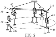
- the device 1 comprises three identical actuators 30, connecting the support 10 to the platform 20.
- the fact that the actuators are identical makes design and manufacture easier. therefore less expensive, and also facilitates the control of the position of the platform.
- Each actuator 30 is linear, that is to say it is adapted to generate a translation movement.
- the screw-nut connection 34 comprises a threaded screw 35 and a threaded nut 36 mounted on the screw.
- the first portion 31 of each actuator is secured to the threaded nut 36, and the second portion 32 is secured to the screw 35.
- each universal joint 310 is adapted to prevent rotation of the first portion 31 in the axis of the linear actuator 30, that is to say in the axis of the screw-nut connection.
- Each universal joint 310 comprises a first part 311 secured to the nut, an intermediate part 312 mounted to rotate with respect to the first part around a respective first axis, one example of which is denoted XX on the figure 2 and 3 , and a third part 313 integral with the platform, and mounted for rotation with respect to the intermediate part around a respective second axis, perpendicular to the first, and an example of which is denoted YY on the picture 2 .
- the axes of rotation of the universal joint connection are advantageously perpendicular to the axis of the screw-nut connection. Blocking this rotation makes it possible to prevent rotation of the nut relative to the screw.
- the motor 33 driving the screw in rotation causes, by this locking in rotation of the nut, the translation of the second portion 32 with respect to the first 31.
- the platform in translation, by an identical and simultaneous translation of the three actuators 30, or to orient the platform, by individually controlling each actuator to obtain the desired orientation, as in the position represented. on the picture 1a .
- This variable orientation of the platform 20 is made possible by the gimbal links on the platform side and the pivot links on the support side.
- the screw-nut connection can be formed by a ball screw or by a roller screw. The fact of using this type of structure of screw-nut connections makes it possible to carry out only transmissions of movement by rotation and not by translation in the device. In fact, in space, sliding connections are not recommended because they present difficulties in controlling friction and play, as well as difficulties in confining the lubricant, which limit the service life of the mechanisms and reduce performance in terms of accuracy or stability.
- the screw-nut connections of the three linear actuators are formed by roller screws, which make it possible to obtain a finer pitch than ball screws, and therefore more precise control.
- the roller screw comprises the screw 35, comprising a barrel 350 and a threaded rod 351, a threaded nut 36 mounted on the threaded rod, the threaded nut 36 comprising a plurality of rollers 360 distributed around the screw.
- the roller screw is lubricated, typically with grease or oil.
- the device 1 since the device 1 is to be used in space, it is necessary to avoid the vaporization of the lubricant, so that the lubrication is maintained throughout the lifetime of the device, and also to avoid possible contamination of other devices or instruments located in the vicinity of it.
- the roller screw comprises a sheath 37 extending around the screw 35 and the nut 36, and which comprises several portions arranged relative to each other to limit the escape of vaporized molecules of lubricant while by allowing the relative movement of the second portion of the actuator with respect to the first.
- the actuators are arranged, relative to the support 10 and to the platform 20, so that the support 10 and the platform 20 are each symmetrical according to a central symmetry, in order to facilitate the control of the actuators.
- the actuators are arranged so that their bases, that is to say the end of the second portion 32 located at the level of the pivot connection 320, are evenly distributed over a circle passing through the axis of each actuator, the axis of the pivot connection 320 of each actuator preferably being tangent to the circle.
- each universal joint 310 connected to the platform are preferably evenly distributed over a circle, the axes of rotation of each part 313 with respect to the intermediate part 312 of the Universal joint being radial with respect to the circle.
- the actuators 30 are therefore suitable for moving the platform 20 relative to the support.
- the actuators 30 are arranged to move the platform 20 from and to a stacked position, shown in the figure 1b , in which the platform 20 bears against the support 10.
- the support is shaped to allow the support of the platform against the latter when the platform is in the stacked position. It may in particular comprise, as represented in the example of the figure 1 , support feet 11 projecting from the wall of the spacecraft on which the device 1 is mounted.
- the support 10 is shaped to have three support points, typically formed by three projecting support feet 11, the three support points being respectively adjacent to each linear actuator 30. Support points are sized to support the weight of the platform and the equipment mounted on it.
- the support 10 and the platform 20 are shaped to be able to block the three degrees of freedom of the platform in the stacked position.
- the support 10 and the platform 20 are shaped to establish, in the stacked position, three connections of the sphere-chute or sphere-V type 40, represented on the figure 5 .
- a connection of the sphere-duct type 40 is a connection obtained by the contact of a sphere or an element having a locally spherical outline 41, formed for example by a surface of the platform 20 or an element attached thereto, on a trough 42, formed for example in a foot 11 of the support, and which forms two point contacts.
- a sphere-chute connection allows a translation along an axis of the chute, and a rotation along three axes, it thus blocks a translation along two axes perpendicular to those of the chute.
- the axes of the sphere-chute connections are therefore not parallel.
- the three sphere-chute connections being regularly distributed along a circle, for example a circle passing through the centers of the spheres 41, the axes of the connections can be radial with respect to this circle.
- This triple connection forms an embedded connection making it possible to immobilize the platform with respect to the support.
- the fact of having recourse to three connections of the sphere-chute type makes it possible to achieve this result by using identical mechanical connections, which makes the device industrially simpler and less expensive to manufacture.
- the deployment and pointing device advantageously comprises a launch holding device adapted to apply a pre-load on the platform 20 towards the support 10, when the platform is in the stacked position at launch, to hold the platform shape pressed against the support despite the efforts and vibrations induced by the launch.
- the launch support device may comprise one or more fuse wires initially maintaining the platform resting against the support, the wire being burned once the device is in orbit, to release the platform.
- the embedding connection formed between the platform and the support creates degrees of hyperstatism at the level of the overall device.
- the support points between the support and the platform are positioned as close as possible to the linear actuators.
- each Cardan-type link 310 between a linear actuator and the platform can comprise flexible strips 314 intended to reduce the forces that can be transmitted at this link, and in particular the forces in the axis of the actuator.
- the threaded screw 35 of the screw-nut connection 34 of each actuator 30 can also be dimensioned to reduce the forces that it can transmit, and in particular the forces transverse to the axis of the actuator, by presenting a sufficiently high length to diameter ratio, which must be determined on a case-by-case basis by the person skilled in the art according to the mass of the pointed equipment, the forces acceptable by the screw, etc. It is nevertheless understood that the flexibilities induced must however be limited in order to maintain good positioning precision of the platform in orbit, this precision having a direct impact on the positioning precision of the equipment mounted on the platform and, in in the case of an optical instrument, on its sharpness.
- the deployment and pointing device 1 therefore makes it possible, thanks to the mechanism described above, both to orient equipment precisely and according to control methods which can be simplified by a symmetry of the device and the identical nature of the actuators, but also to return the platform and the equipment to a stacked position where launch support can be ensured. As a result, resistance to the forces generated by the launch is ensured without the need to oversize the actuators or the joints or to preload them, which would increase the mass and the cost of the equipment.
- the device is therefore initially mounted in the stacked position, the mobile platform being held in abutment against the support by means of a launch holding device. Once launched, the platform is released and the linear actuators can be controlled to first move the platform away from the support by means of a translation, for example perpendicular to the plane of the support, then to orient the platform. -shape and therefore the equipment in at least one predetermined direction.
- the device may comprise an electronic control card integrating a computer and a memory storing instructions necessary for controlling the actuators to execute a series of predefined movements.
- the device can comprise a remote communication interface making it possible to receive control instructions transmitted from a ground station.
Landscapes
- Engineering & Computer Science (AREA)
- Remote Sensing (AREA)
- General Engineering & Computer Science (AREA)
- Aviation & Aerospace Engineering (AREA)
- Mechanical Engineering (AREA)
- Physics & Mathematics (AREA)
- Astronomy & Astrophysics (AREA)
- General Physics & Mathematics (AREA)
- Transmission Devices (AREA)
Claims (12)
- Vorrichtung (1) zum Errichten und Ausrichten eines Geräts, aufweisend:- eine mobile Geräteaufnahmeplattform (20) zum Aufnehmen des Geräts,- einen an einer Wand eines Raumfahrzeugs befestigten Träger (10), und- drei identische lineare Aktuatoren (30), die den Träger mit der mobilen Plattform verbinden,wobei die Aktuatoren (30) angepasst sind, um die mobile Plattform durch Translation entlang einer Achse zu bewegen und um die mobile Plattform durch Rotation um zwei Achsen zu orientieren,
dadurch gekennzeichnet, dass jeder lineare Aktuator (30) aufweist:- einen ersten Abschnitt (31), der über eine Kardan-Verbindung (310) mit der mobilen Plattform (20) verbunden ist,- einen zweiten Abschnitt (32), der über eine Drehverbindung (320) mit dem Träger verbunden ist,- einen Motor (33) und- eine Schraube-Mutter-Verbindung (34), die den ersten (31) und den zweiten Abschnitt (32) miteinander verbindet,wobei die Kardan-Verbindung (310) jedes Aktuators angepasst ist, um eine Rotation in der Achse der Schraube-Mutter-Verbindung (34) zu verhindern, so dass das Rotieren der Schraube oder der Mutter durch den Motor eine Translation zwischen dem ersten (31) und dem zweiten Abschnitt (32) zur Folge hat. - Vorrichtung nach Anspruch 1, in welcher die linearen Aktuatoren (30) angepasst sind, um die mobile Geräteaufnahmeplattform (20) zwischen einer gestapelten Position und mindestens einer Betriebsposition zu bewegen, und der Träger (10) und die mobile Plattform (20) konfiguriert sind, so dass in der gestapelten Position die mobile Plattform über drei Auflagepunkte, die jeweils an jeden linearen Aktuator angrenzen, auf dem Träger aufliegt.
- Vorrichtung nach dem vorstehenden Anspruch, in welcher die mobile Plattform (20) und der Träger (10) konfiguriert sind, um in der gestapelten Position drei Verbindungen des Typs Kugel-Rinne (40) zwischen der mobilen Plattform (20) und dem Träger (10) zu bilden, wobei die Achsen der Kugel-Rinne-Verbindungen (40) zueinander nicht parallel sind.
- Vorrichtung nach dem vorstehenden Anspruch, in welcher die drei Kugel-Rinne-Verbindungen (40) gleichmäßig auf einem Kreis verteilt sind, wobei die Achsen der Rinnen (42) sich radial bezüglich des Kreises erstrecken.
- Vorrichtung nach einem der Ansprüche 2 bis 4, aufweisend ferner eine Startfesthaltevorrichtung, die angepasst ist, um beim Start des Raumfahrzeugs die mobile Plattform in der gestapelten Position auf dem Träger aufliegend zu halten.
- Vorrichtung nach einem der Ansprüche 2 bis 5, wobei die Vorrichtung (1) ferner dimensioniert ist, um in der gestapelten Position eine Übertragung größerer Belastungen über die Auflagepunkte als über die linearen Aktuatoren (30) zu erlauben.
- Vorrichtung (1) nach dem vorstehenden Anspruch, in welcher jede Kardan-Verbindung (310) mindestens eine flexible Lamelle (314) aufweist, die angepasst ist, um die Belastungen, die von der Plattform (20) auf den entsprechenden linearen Aktuator übertragen werden können, zu begrenzen.
- Vorrichtung nach einem der vorstehenden Ansprüche, in welcher die Aktuatoren (30) relativ zu dem Träger (10) und zu der Aufnahmeplattform (20) angeordnet sind, derart, dass sowohl der Träger (10) als auch die Plattform (20) symmetrisch bezüglich einer zentralen Symmetrieachse sind.
- Vorrichtung nach einem der vorstehenden Ansprüche, in welcher jede Schraube-Mutter-Verbindung (34) eine Rollenschraube aufweist.
- Vorrichtung nach dem vorstehenden Anspruch, in welcher die Rollenschraube eine Schraube (35) mit einem Schaft (350) und einer Gewindestange (351), eine an der Gewindestange angebrachte Gewindemutter (36) und eine Hülse (37) aufweist, die sich um die Schraube (35) und die Mutter (36) herum erstreckt und ein Schmiermittel beherbergt, wobei die Hülse aufweist:- einen ersten Hülsenabschnitt (370), der mit der Mutter (36) verbunden ist und das freie Ende der Gewindestange der Schraube bedeckt, wobei der erste Hülsenabschnitt an einem Ende, das sich an dem freien Ende der Gewindestange befindet, geschlossen ist,- einen zweiten fixierten Hülsenabschnitt (371), der den Schaft der Schraube bedeckt,- einen dritten Hülsenabschnitt (372), der über den zweiten Abschnitt (371) gleitbar angebracht ist, und- einen vierten Hülsenabschnitt (373), der mit der Mutter verbunden ist und sich von der Mutter (36) aus hin zu dem Schaft der Schraube erstreckt, um so den dritten Abschnitt (372) teilweise zu bedecken,wobei der dritte (372) und der vierte (373) Hülsenabschnitt konfiguriert sind, um das Entweichen von Schmiermittel aus der Hülse zu verhindern.
- Verfahren zum Errichten einer an einem Satelliten angebrachten Vorrichtung (1) nach einem der vorstehenden Ansprüche, wobei die Vorrichtung anfangs in einer Stapelposition ist, in welcher die mobile Plattform (20) auf dem Träger (10) aufliegt,
wobei das Verfahren aufweist: Betätigen jedes linearen Aktuators (30), um die mobile Plattform durch Translation von dem Träger weg zu bewegen, und Betätigen jedes Aktuators, um die Plattform in mindestens eine vorgegebene Richtung zu orientieren. - Computerprogrammprodukt aufweisend Codebefehle zum Durchführen des Verfahrens nach dem vorstehenden Anspruch, wenn es von einem Rechner ausgeführt wird.
Applications Claiming Priority (2)
| Application Number | Priority Date | Filing Date | Title |
|---|---|---|---|
| FR2004989A FR3110550B1 (fr) | 2020-05-19 | 2020-05-19 | Dispositif de déploiement et de pointage d’un équipement porté par un engin spatial |
| PCT/FR2021/050813 WO2021234246A1 (fr) | 2020-05-19 | 2021-05-11 | Dispositif de déploiement et de pointage d'un équipement porté par un engin spatial |
Publications (2)
| Publication Number | Publication Date |
|---|---|
| EP3947158A1 EP3947158A1 (de) | 2022-02-09 |
| EP3947158B1 true EP3947158B1 (de) | 2022-04-27 |
Family
ID=72560700
Family Applications (1)
| Application Number | Title | Priority Date | Filing Date |
|---|---|---|---|
| EP21731248.7A Active EP3947158B1 (de) | 2020-05-19 | 2021-05-11 | Vorrichtung zum auslösen und zeigen eines von einem raumfahrzeug getragenen geräteteils |
Country Status (6)
| Country | Link |
|---|---|
| US (1) | US11834202B2 (de) |
| EP (1) | EP3947158B1 (de) |
| AU (1) | AU2021276587B2 (de) |
| ES (1) | ES2914598T3 (de) |
| FR (1) | FR3110550B1 (de) |
| WO (1) | WO2021234246A1 (de) |
Cited By (1)
| Publication number | Priority date | Publication date | Assignee | Title |
|---|---|---|---|---|
| WO2026041810A1 (fr) * | 2024-08-22 | 2026-02-26 | Spacelocker | Interface de sécurisation d'une charge à une plateforme fixée à un lanceur spatial ou un satellite |
Families Citing this family (2)
| Publication number | Priority date | Publication date | Assignee | Title |
|---|---|---|---|---|
| CN114084210B (zh) * | 2021-12-02 | 2023-05-30 | 中国船舶工业系统工程研究院 | 一种三维移动操作台及其应用的无人机载荷承载托架 |
| CN117508660B (zh) * | 2023-10-24 | 2024-11-05 | 哈尔滨工业大学 | 基于机械臂辅助的齿轮传动式板状载荷重复锁紧释放装置 |
Family Cites Families (8)
| Publication number | Priority date | Publication date | Assignee | Title |
|---|---|---|---|---|
| FR2672836B1 (fr) * | 1991-02-15 | 1995-06-02 | Onera (Off Nat Aerospatiale) | Dispositif d'articulation a structure parallele et appareils de transmission de mouvement a distance en faisant application. |
| KR100334902B1 (ko) * | 1999-12-06 | 2002-05-04 | 윤덕용 | 정밀작업용 6자유도 병렬기구 |
| FR2989229B1 (fr) * | 2012-04-06 | 2015-03-06 | Thales Sa | Reflecteur d'antenne reconfigurable en service |
| US9694455B2 (en) * | 2012-12-05 | 2017-07-04 | Alio Industries, Inc. | Precision tripod motion system with six degrees of freedom |
| US11077547B2 (en) * | 2014-05-08 | 2021-08-03 | Universite Laval | Parallel mechanism with kinematically redundant actuation |
| FR3048418B1 (fr) | 2016-03-02 | 2019-04-19 | Thales | Dispositif de deploiement et de pointage |
| EP3249632A1 (de) * | 2016-05-26 | 2017-11-29 | E2M Technologies B.V. | Bewegungsplattformsystem |
| FR3079281B1 (fr) * | 2018-03-22 | 2020-03-20 | Thales | Dispositif de positionnement |
-
2020
- 2020-05-19 FR FR2004989A patent/FR3110550B1/fr active Active
-
2021
- 2021-05-11 ES ES21731248T patent/ES2914598T3/es active Active
- 2021-05-11 AU AU2021276587A patent/AU2021276587B2/en active Active
- 2021-05-11 EP EP21731248.7A patent/EP3947158B1/de active Active
- 2021-05-11 US US17/926,044 patent/US11834202B2/en active Active
- 2021-05-11 WO PCT/FR2021/050813 patent/WO2021234246A1/fr not_active Ceased
Cited By (2)
| Publication number | Priority date | Publication date | Assignee | Title |
|---|---|---|---|---|
| WO2026041810A1 (fr) * | 2024-08-22 | 2026-02-26 | Spacelocker | Interface de sécurisation d'une charge à une plateforme fixée à un lanceur spatial ou un satellite |
| FR3165688A1 (fr) * | 2024-08-22 | 2026-02-27 | Spacelocker | Interface de sécurisation d’une charge à une plateforme fixée à un lanceur spatial ou un satellite |
Also Published As
| Publication number | Publication date |
|---|---|
| FR3110550B1 (fr) | 2022-05-20 |
| FR3110550A1 (fr) | 2021-11-26 |
| US11834202B2 (en) | 2023-12-05 |
| EP3947158A1 (de) | 2022-02-09 |
| US20230182926A1 (en) | 2023-06-15 |
| AU2021276587B2 (en) | 2023-01-05 |
| ES2914598T3 (es) | 2022-06-14 |
| WO2021234246A1 (fr) | 2021-11-25 |
| AU2021276587A1 (en) | 2022-12-15 |
Similar Documents
| Publication | Publication Date | Title |
|---|---|---|
| EP3947158B1 (de) | Vorrichtung zum auslösen und zeigen eines von einem raumfahrzeug getragenen geräteteils | |
| EP3390230B1 (de) | Verfahren zur steuerung der lageführung eines satelliten, satelliten, mehrere satelliten und zugehöriges computerprogramm | |
| EP3962816B1 (de) | Vorrichtung zur dämpfung des andockens an einen satelliten | |
| EP2468629B1 (de) | Entfaltbare starre Großstrukturen | |
| EP3174794B1 (de) | Satellit mit einem optischen fotoapparat | |
| WO1996039328A1 (fr) | Dispositif adaptateur basculant pour l'emport de plusieurs charges utiles sur un meme lanceur | |
| EP1964778B1 (de) | Drehgelenk mit Blattfedern | |
| EP3045396B1 (de) | Ausrichtungseinheit eines instrumentes | |
| EP3213999B1 (de) | Vorrichtung zur entfaltung und ausrichtung | |
| FR2780774A1 (fr) | Dispositif d'autoprotection passive pour engin mobile tel qu'un helicoptere | |
| FR2669972A1 (fr) | Dispositif d'assujettissement temporaire d'un objet a un support a douille de retenue monobloc. | |
| EP3135971B1 (de) | Verbessertes system zum bremsen eines ventils | |
| WO2015101723A1 (fr) | Structure segmentée, en particulier pour réflecteur d'antenne de satellite, pourvue d'au moins un dispositif de déploiement à rotation et translation | |
| EP1377863A1 (de) | In dem schatten eines spiegels aufgestelltes montage- und justiergerät für diesen spiegel und mit diesem gerät versehenes optisches system | |
| EP4627400B1 (de) | Kompaktes einsetzbares optomechanisches system | |
| EP1635485B1 (de) | Optisches Übertragungsverfahren zwischen einem Terminal an Bord eines Raumfahrzeuges, und Raumfahrzeug für das Verfahren | |
| EP0455543B1 (de) | Vorrichtung zur Ausrichtung einer Reflektorantenne | |
| EP3947160B1 (de) | Geostationärer satellit umfassend einen strahler mit verminderter sonneneinstrahlung und verbessertem führungssystem | |
| EP2927992B1 (de) | Mechanisches halterungssystem zum fixieren einer batterie in einem röhrenförmigen fach | |
| FR3131281A1 (fr) | Systeme d'equilibrage du centre d'inertie d'un satellite de telecommunications. |
Legal Events
| Date | Code | Title | Description |
|---|---|---|---|
| STAA | Information on the status of an ep patent application or granted ep patent |
Free format text: STATUS: UNKNOWN |
|
| STAA | Information on the status of an ep patent application or granted ep patent |
Free format text: STATUS: THE INTERNATIONAL PUBLICATION HAS BEEN MADE |
|
| PUAI | Public reference made under article 153(3) epc to a published international application that has entered the european phase |
Free format text: ORIGINAL CODE: 0009012 |
|
| STAA | Information on the status of an ep patent application or granted ep patent |
Free format text: STATUS: REQUEST FOR EXAMINATION WAS MADE |
|
| GRAP | Despatch of communication of intention to grant a patent |
Free format text: ORIGINAL CODE: EPIDOSNIGR1 |
|
| STAA | Information on the status of an ep patent application or granted ep patent |
Free format text: STATUS: GRANT OF PATENT IS INTENDED |
|
| 17P | Request for examination filed |
Effective date: 20211027 |
|
| AK | Designated contracting states |
Kind code of ref document: A1 Designated state(s): AL AT BE BG CH CY CZ DE DK EE ES FI FR GB GR HR HU IE IS IT LI LT LU LV MC MK MT NL NO PL PT RO RS SE SI SK SM TR |
|
| INTG | Intention to grant announced |
Effective date: 20220117 |
|
| GRAS | Grant fee paid |
Free format text: ORIGINAL CODE: EPIDOSNIGR3 |
|
| GRAA | (expected) grant |
Free format text: ORIGINAL CODE: 0009210 |
|
| STAA | Information on the status of an ep patent application or granted ep patent |
Free format text: STATUS: THE PATENT HAS BEEN GRANTED |
|
| AK | Designated contracting states |
Kind code of ref document: B1 Designated state(s): AL AT BE BG CH CY CZ DE DK EE ES FI FR GB GR HR HU IE IS IT LI LT LU LV MC MK MT NL NO PL PT RO RS SE SI SK SM TR |
|
| DAV | Request for validation of the european patent (deleted) | ||
| DAX | Request for extension of the european patent (deleted) | ||
| REG | Reference to a national code |
Ref country code: GB Ref legal event code: FG4D Free format text: NOT ENGLISH |
|
| REG | Reference to a national code |
Ref country code: CH Ref legal event code: EP |
|
| REG | Reference to a national code |
Ref country code: AT Ref legal event code: REF Ref document number: 1486790 Country of ref document: AT Kind code of ref document: T Effective date: 20220515 |
|
| REG | Reference to a national code |
Ref country code: DE Ref legal event code: R096 Ref document number: 602021000078 Country of ref document: DE |
|
| REG | Reference to a national code |
Ref country code: IE Ref legal event code: FG4D Free format text: LANGUAGE OF EP DOCUMENT: FRENCH |
|
| REG | Reference to a national code |
Ref country code: ES Ref legal event code: FG2A Ref document number: 2914598 Country of ref document: ES Kind code of ref document: T3 Effective date: 20220614 |
|
| REG | Reference to a national code |
Ref country code: NL Ref legal event code: FP |
|
| REG | Reference to a national code |
Ref country code: LT Ref legal event code: MG9D |
|
| REG | Reference to a national code |
Ref country code: AT Ref legal event code: MK05 Ref document number: 1486790 Country of ref document: AT Kind code of ref document: T Effective date: 20220427 |
|
| PG25 | Lapsed in a contracting state [announced via postgrant information from national office to epo] |
Ref country code: SE Free format text: LAPSE BECAUSE OF FAILURE TO SUBMIT A TRANSLATION OF THE DESCRIPTION OR TO PAY THE FEE WITHIN THE PRESCRIBED TIME-LIMIT Effective date: 20220427 Ref country code: PT Free format text: LAPSE BECAUSE OF FAILURE TO SUBMIT A TRANSLATION OF THE DESCRIPTION OR TO PAY THE FEE WITHIN THE PRESCRIBED TIME-LIMIT Effective date: 20220829 Ref country code: NO Free format text: LAPSE BECAUSE OF FAILURE TO SUBMIT A TRANSLATION OF THE DESCRIPTION OR TO PAY THE FEE WITHIN THE PRESCRIBED TIME-LIMIT Effective date: 20220727 Ref country code: LT Free format text: LAPSE BECAUSE OF FAILURE TO SUBMIT A TRANSLATION OF THE DESCRIPTION OR TO PAY THE FEE WITHIN THE PRESCRIBED TIME-LIMIT Effective date: 20220427 Ref country code: HR Free format text: LAPSE BECAUSE OF FAILURE TO SUBMIT A TRANSLATION OF THE DESCRIPTION OR TO PAY THE FEE WITHIN THE PRESCRIBED TIME-LIMIT Effective date: 20220427 Ref country code: GR Free format text: LAPSE BECAUSE OF FAILURE TO SUBMIT A TRANSLATION OF THE DESCRIPTION OR TO PAY THE FEE WITHIN THE PRESCRIBED TIME-LIMIT Effective date: 20220728 Ref country code: FI Free format text: LAPSE BECAUSE OF FAILURE TO SUBMIT A TRANSLATION OF THE DESCRIPTION OR TO PAY THE FEE WITHIN THE PRESCRIBED TIME-LIMIT Effective date: 20220427 Ref country code: BG Free format text: LAPSE BECAUSE OF FAILURE TO SUBMIT A TRANSLATION OF THE DESCRIPTION OR TO PAY THE FEE WITHIN THE PRESCRIBED TIME-LIMIT Effective date: 20220727 Ref country code: AT Free format text: LAPSE BECAUSE OF FAILURE TO SUBMIT A TRANSLATION OF THE DESCRIPTION OR TO PAY THE FEE WITHIN THE PRESCRIBED TIME-LIMIT Effective date: 20220427 |
|
| PG25 | Lapsed in a contracting state [announced via postgrant information from national office to epo] |
Ref country code: RS Free format text: LAPSE BECAUSE OF FAILURE TO SUBMIT A TRANSLATION OF THE DESCRIPTION OR TO PAY THE FEE WITHIN THE PRESCRIBED TIME-LIMIT Effective date: 20220427 Ref country code: PL Free format text: LAPSE BECAUSE OF FAILURE TO SUBMIT A TRANSLATION OF THE DESCRIPTION OR TO PAY THE FEE WITHIN THE PRESCRIBED TIME-LIMIT Effective date: 20220427 Ref country code: LV Free format text: LAPSE BECAUSE OF FAILURE TO SUBMIT A TRANSLATION OF THE DESCRIPTION OR TO PAY THE FEE WITHIN THE PRESCRIBED TIME-LIMIT Effective date: 20220427 Ref country code: IS Free format text: LAPSE BECAUSE OF FAILURE TO SUBMIT A TRANSLATION OF THE DESCRIPTION OR TO PAY THE FEE WITHIN THE PRESCRIBED TIME-LIMIT Effective date: 20220827 |
|
| REG | Reference to a national code |
Ref country code: DE Ref legal event code: R097 Ref document number: 602021000078 Country of ref document: DE |
|
| PG25 | Lapsed in a contracting state [announced via postgrant information from national office to epo] |
Ref country code: SM Free format text: LAPSE BECAUSE OF FAILURE TO SUBMIT A TRANSLATION OF THE DESCRIPTION OR TO PAY THE FEE WITHIN THE PRESCRIBED TIME-LIMIT Effective date: 20220427 Ref country code: SK Free format text: LAPSE BECAUSE OF FAILURE TO SUBMIT A TRANSLATION OF THE DESCRIPTION OR TO PAY THE FEE WITHIN THE PRESCRIBED TIME-LIMIT Effective date: 20220427 Ref country code: RO Free format text: LAPSE BECAUSE OF FAILURE TO SUBMIT A TRANSLATION OF THE DESCRIPTION OR TO PAY THE FEE WITHIN THE PRESCRIBED TIME-LIMIT Effective date: 20220427 Ref country code: MC Free format text: LAPSE BECAUSE OF FAILURE TO SUBMIT A TRANSLATION OF THE DESCRIPTION OR TO PAY THE FEE WITHIN THE PRESCRIBED TIME-LIMIT Effective date: 20220427 Ref country code: EE Free format text: LAPSE BECAUSE OF FAILURE TO SUBMIT A TRANSLATION OF THE DESCRIPTION OR TO PAY THE FEE WITHIN THE PRESCRIBED TIME-LIMIT Effective date: 20220427 Ref country code: DK Free format text: LAPSE BECAUSE OF FAILURE TO SUBMIT A TRANSLATION OF THE DESCRIPTION OR TO PAY THE FEE WITHIN THE PRESCRIBED TIME-LIMIT Effective date: 20220427 Ref country code: CZ Free format text: LAPSE BECAUSE OF FAILURE TO SUBMIT A TRANSLATION OF THE DESCRIPTION OR TO PAY THE FEE WITHIN THE PRESCRIBED TIME-LIMIT Effective date: 20220427 |
|
| PLBE | No opposition filed within time limit |
Free format text: ORIGINAL CODE: 0009261 |
|
| STAA | Information on the status of an ep patent application or granted ep patent |
Free format text: STATUS: NO OPPOSITION FILED WITHIN TIME LIMIT |
|
| PG25 | Lapsed in a contracting state [announced via postgrant information from national office to epo] |
Ref country code: AL Free format text: LAPSE BECAUSE OF FAILURE TO SUBMIT A TRANSLATION OF THE DESCRIPTION OR TO PAY THE FEE WITHIN THE PRESCRIBED TIME-LIMIT Effective date: 20220427 |
|
| 26N | No opposition filed |
Effective date: 20230130 |
|
| REG | Reference to a national code |
Ref country code: BE Ref legal event code: MM Effective date: 20230531 |
|
| PG25 | Lapsed in a contracting state [announced via postgrant information from national office to epo] |
Ref country code: LU Free format text: LAPSE BECAUSE OF NON-PAYMENT OF DUE FEES Effective date: 20230511 |
|
| REG | Reference to a national code |
Ref country code: IE Ref legal event code: MM4A |
|
| PG25 | Lapsed in a contracting state [announced via postgrant information from national office to epo] |
Ref country code: IE Free format text: LAPSE BECAUSE OF NON-PAYMENT OF DUE FEES Effective date: 20230511 |
|
| PG25 | Lapsed in a contracting state [announced via postgrant information from national office to epo] |
Ref country code: IE Free format text: LAPSE BECAUSE OF NON-PAYMENT OF DUE FEES Effective date: 20230511 |
|
| PG25 | Lapsed in a contracting state [announced via postgrant information from national office to epo] |
Ref country code: HU Free format text: LAPSE BECAUSE OF FAILURE TO SUBMIT A TRANSLATION OF THE DESCRIPTION OR TO PAY THE FEE WITHIN THE PRESCRIBED TIME-LIMIT; INVALID AB INITIO Effective date: 20210511 Ref country code: BE Free format text: LAPSE BECAUSE OF NON-PAYMENT OF DUE FEES Effective date: 20230531 |
|
| PG25 | Lapsed in a contracting state [announced via postgrant information from national office to epo] |
Ref country code: BG Free format text: LAPSE BECAUSE OF FAILURE TO SUBMIT A TRANSLATION OF THE DESCRIPTION OR TO PAY THE FEE WITHIN THE PRESCRIBED TIME-LIMIT Effective date: 20220427 |
|
| PG25 | Lapsed in a contracting state [announced via postgrant information from national office to epo] |
Ref country code: BG Free format text: LAPSE BECAUSE OF FAILURE TO SUBMIT A TRANSLATION OF THE DESCRIPTION OR TO PAY THE FEE WITHIN THE PRESCRIBED TIME-LIMIT Effective date: 20220427 |
|
| REG | Reference to a national code |
Ref country code: DE Ref legal event code: R082 Ref document number: 602021000078 Country of ref document: DE Representative=s name: PLASSERAUD IP GMBH, DE |
|
| PGFP | Annual fee paid to national office [announced via postgrant information from national office to epo] |
Ref country code: NL Payment date: 20250521 Year of fee payment: 5 |
|
| PGFP | Annual fee paid to national office [announced via postgrant information from national office to epo] |
Ref country code: DE Payment date: 20250521 Year of fee payment: 5 |
|
| PGFP | Annual fee paid to national office [announced via postgrant information from national office to epo] |
Ref country code: GB Payment date: 20250527 Year of fee payment: 5 |
|
| PGFP | Annual fee paid to national office [announced via postgrant information from national office to epo] |
Ref country code: IT Payment date: 20250527 Year of fee payment: 5 |
|
| PGFP | Annual fee paid to national office [announced via postgrant information from national office to epo] |
Ref country code: FR Payment date: 20250528 Year of fee payment: 5 |
|
| PGFP | Annual fee paid to national office [announced via postgrant information from national office to epo] |
Ref country code: CH Payment date: 20250601 Year of fee payment: 5 |
|
| PG25 | Lapsed in a contracting state [announced via postgrant information from national office to epo] |
Ref country code: CY Free format text: LAPSE BECAUSE OF FAILURE TO SUBMIT A TRANSLATION OF THE DESCRIPTION OR TO PAY THE FEE WITHIN THE PRESCRIBED TIME-LIMIT; INVALID AB INITIO Effective date: 20210511 |
|
| PGFP | Annual fee paid to national office [announced via postgrant information from national office to epo] |
Ref country code: ES Payment date: 20250630 Year of fee payment: 5 |
|
| PG25 | Lapsed in a contracting state [announced via postgrant information from national office to epo] |
Ref country code: TR Free format text: LAPSE BECAUSE OF FAILURE TO SUBMIT A TRANSLATION OF THE DESCRIPTION OR TO PAY THE FEE WITHIN THE PRESCRIBED TIME-LIMIT Effective date: 20220427 |
|
| PG25 | Lapsed in a contracting state [announced via postgrant information from national office to epo] |
Ref country code: SI Free format text: LAPSE BECAUSE OF FAILURE TO SUBMIT A TRANSLATION OF THE DESCRIPTION OR TO PAY THE FEE WITHIN THE PRESCRIBED TIME-LIMIT Effective date: 20220427 |