EP3947892B1 - Unterirdisches bohrgestell und systeme und verfahren zu dessen verwendung - Google Patents
Unterirdisches bohrgestell und systeme und verfahren zu dessen verwendung Download PDFInfo
- Publication number
- EP3947892B1 EP3947892B1 EP20784379.8A EP20784379A EP3947892B1 EP 3947892 B1 EP3947892 B1 EP 3947892B1 EP 20784379 A EP20784379 A EP 20784379A EP 3947892 B1 EP3947892 B1 EP 3947892B1
- Authority
- EP
- European Patent Office
- Prior art keywords
- drill
- drill string
- overshot
- spindle
- assembly
- Prior art date
- Legal status (The legal status is an assumption and is not a legal conclusion. Google has not performed a legal analysis and makes no representation as to the accuracy of the status listed.)
- Active
Links
Images













Classifications
-
- E—FIXED CONSTRUCTIONS
- E21—EARTH OR ROCK DRILLING; MINING
- E21B—EARTH OR ROCK DRILLING; OBTAINING OIL, GAS, WATER, SOLUBLE OR MELTABLE MATERIALS OR A SLURRY OF MINERALS FROM WELLS
- E21B19/00—Handling rods, casings, tubes or the like outside the borehole, e.g. in the derrick; Apparatus for feeding the rods or cables
- E21B19/08—Apparatus for feeding the rods or cables; Apparatus for increasing or decreasing the pressure on the drilling tool; Apparatus for counterbalancing the weight of the rods
-
- E—FIXED CONSTRUCTIONS
- E21—EARTH OR ROCK DRILLING; MINING
- E21B—EARTH OR ROCK DRILLING; OBTAINING OIL, GAS, WATER, SOLUBLE OR MELTABLE MATERIALS OR A SLURRY OF MINERALS FROM WELLS
- E21B15/00—Supports for the drilling machine, e.g. derricks or masts
- E21B15/006—Means for anchoring the drilling machine to the ground
-
- E—FIXED CONSTRUCTIONS
- E21—EARTH OR ROCK DRILLING; MINING
- E21B—EARTH OR ROCK DRILLING; OBTAINING OIL, GAS, WATER, SOLUBLE OR MELTABLE MATERIALS OR A SLURRY OF MINERALS FROM WELLS
- E21B15/00—Supports for the drilling machine, e.g. derricks or masts
- E21B15/04—Supports for the drilling machine, e.g. derricks or masts specially adapted for directional drilling, e.g. slant hole rigs
-
- E—FIXED CONSTRUCTIONS
- E21—EARTH OR ROCK DRILLING; MINING
- E21B—EARTH OR ROCK DRILLING; OBTAINING OIL, GAS, WATER, SOLUBLE OR MELTABLE MATERIALS OR A SLURRY OF MINERALS FROM WELLS
- E21B19/00—Handling rods, casings, tubes or the like outside the borehole, e.g. in the derrick; Apparatus for feeding the rods or cables
- E21B19/20—Combined feeding from rack and connecting, e.g. automatically
-
- E—FIXED CONSTRUCTIONS
- E21—EARTH OR ROCK DRILLING; MINING
- E21B—EARTH OR ROCK DRILLING; OBTAINING OIL, GAS, WATER, SOLUBLE OR MELTABLE MATERIALS OR A SLURRY OF MINERALS FROM WELLS
- E21B21/00—Methods or apparatus for flushing boreholes, e.g. by use of exhaust air from motor
- E21B21/02—Swivel joints in hose-lines
-
- E—FIXED CONSTRUCTIONS
- E21—EARTH OR ROCK DRILLING; MINING
- E21B—EARTH OR ROCK DRILLING; OBTAINING OIL, GAS, WATER, SOLUBLE OR MELTABLE MATERIALS OR A SLURRY OF MINERALS FROM WELLS
- E21B7/00—Special methods or apparatus for drilling
- E21B7/02—Drilling rigs characterised by means for land transport with their own drive, e.g. skid mounting or wheel mounting
Definitions
- This application relates to underground drill rigs, and, in particular, to systems for reducing a need for an operator to physically interact with drill rig components during use.
- Drill rigs particularly for underground mining, typically require an operator to physically interact with a drill rig to anchor the drill rig in place, to add drill rods to a drill string, and to operate equipment, such as a wireline overshot. Operation of such drill rigs can be costly and require further expensive ventilation equipment for the operator. Accordingly, drill rigs comprising systems for minimizing or eliminating physical operator interaction with the drill rigs can be desirable.
- An example of a drill rig known in the art is disclosed in US patent number 3,994,350 .
- a drill rod can refer to one or more of such drill rods, and so forth.
- Ranges can be expressed herein as from “about” one particular value, and/or to "about” another particular value. When such a range is expressed, another aspect includes from the one particular value and/or to the other particular value. Similarly, when values are expressed as approximations, by use of the antecedent “about,” it will be understood that the particular value forms another aspect. It will be further understood that the endpoints of each of the ranges are significant both in relation to the other endpoint, and independently of the other endpoint. Optionally, in some aspects, when values are approximated by use of the antecedent "about,” it is contemplated that values within up to 15%, up to 10%, up to 5%, or up to 1% (above or below) of the particularly stated value can be included within the scope of those aspects.
- the terms "optional” or “optionally” mean that the subsequently described event or circumstance may or may not occur, and that the description includes instances where said event or circumstance occurs and instances where it does not.
- the term "at least one of” is intended to be synonymous with “one or more of.”
- “at least one of A, B and C” explicitly includes only A, only B, only C, and combinations of each.
- underground drill rigs and drill rig components that provide the mechanical functions required for completely autonomous drilling, in conjunction with a robotic rod handler as is known in the art.
- the disclosed drill rig components can allow for completion of a drilling process without the need for physical intervention by a person (drill operator).
- the drill rig components can include a second head assembly that operates separately from a first head assembly.
- the disclosed second head assembly can perform the following functions in a hands-free and automated manner (in contrast to conventional systems that require manual labor for completion of these tasks): (a) connecting a water supply rotary union (water swivel) to the end of the last drill rod in a drill string for the purpose of supplying water to the drill string while drilling; connecting a hauling device to the drill string for the purpose of very quickly adding or removing rods from the drill string; and connecting a loading chamber to the drill string for the purpose of putting an overshot into the drill string for retrieving the core sample.
- a water supply rotary union water swivel
- anchoring systems and methods for fully automated/mechanized anchoring (without physical, manual intervention by a drill operator) of an underground drill rig.
- anchoring systems and methods can be used with the drill rigs disclosed herein.
- it is contemplated that such anchoring systems and methods can be used with any conventional drill rig.
- a drill rig 100 can be used in underground drilling operations.
- the drill rig 100 can comprise a feedframe 105 and a first head assembly 110 that is movable on the feedframe 105.
- the first head assembly 110 can be configured to grip drill rods 140 and casings.
- the first head assembly 110 can comprise a conventional chuck drive rotation unit as is known in the art.
- One drill rod 140 can be threadedly coupled to additional drill rods 140 to create a drill string 150.
- the drill string 150 can be coupled to a drill bit 160 or other in-hole tool configured to interface with the material to be drilled, such as a formation 165 (e.g., an underground formation, such as a rock formation).
- a core tube assembly 188 i.e., a core barrel assembly
- the drill string 150 can be coupled to a drill bit 160 or other in-hole tool configured to interface with the material to be drilled, such as a formation 165 (e.g., an underground formation, such as a rock formation).
- a core tube assembly 188 i.e., a core barrel assembly
- the drill string 150 can be coupled to a drill bit 160 or other in-hole tool configured to interface with the material to be drilled, such as a formation 165 (e.g., an underground formation, such as a rock formation).
- a core tube assembly 188 i.e., a core barrel assembly
- the material to be drilled e.g., a core sample
- the feedframe 105 can be oriented such that the drill string 150 is generally horizontal or oriented upwardly relative to the horizontal, as shown in Figure 1 , or, as illustrated in Figure 3 , oriented downwardly relative to the horizontal.
- the drill rig 100 can thus have a longitudinal drilling axis 180 extending between a front portion 182 and a rear portion 184 of the drill rig 100.
- the first head assembly 110 is configured to rotate the drill string 150 during a drilling process.
- the first head assembly 110 may vary the speed at which the drill string 150 rotates as well as the direction of rotation.
- the rotational rate of the drill head and/or the torque the first head assembly 110 transmits to the drill string 150 may be selected as desired according to the drilling process.
- the drill rig can comprise a rod holder 172, or foot clamp, that is configured to grip the drill string 150.
- the drill rig 100 can further comprise a wireline winch 190 that can be used to retract a wireline cable in a conventional manner.
- the wireline cable can be coupled to an overshot to permit retrieval of the overshot.
- the overshot can be pumped down to engage the core tube assembly 188, and the wireline winch 190 can retract the overshot with the core tube assembly 188 attached thereto. In this way, the drilling system can be used to retrieve core samples.
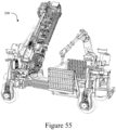
- a drilling system 200 can include the drill rig 100 and a support platform 202, which can optionally be movable about wheels 204 and supported by at least one jack 206 (optionally, a plurality of jacks).
- a rod handler 210 can couple to the platform 202.
- the support platform can be movable about a plurality wheels 202 that can be hydraulically or electrically driven.
- hydraulic motors 208 can rotatably drive the wheels 204.
- Some or all of the wheels 204 can couple to the support platform 202 via jacks 206 so that the wheels 204 are independently vertically movable with respect to the support platform 202 in order to orient the platform 202 (e.g., so that the platform is level).
- some or all of the wheels 204 can be pivotable about respective vertical axes so that the platform can be steered in order to position the platform.
- the movement of the wheels 204 can be controlled remotely (e.g., via a wireless connection with a tablet, smartphone, or other remote computing device).
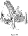
- the drilling system 200 can have a rack for holding drill rods 140 and other equipment (e.g., the casing pipe, one or more overshot assemblies, the extension rod, etc.).
- the drilling system of Figure 53 can optionally have the some or all of the features of the drill rig 100 as described with reference to Figure 2 .
- the rod handler 210 can comprise a robotic arm 212 and a pair of jaws 214 that are configured to selectively grab the drill rods 140 to feed to, and remove from, the drill rig 100.
- the rod handler 210 can employ switchable magnets (e.g., electromagnets) to selectively grip and release the drill rods 140.
- the rod handler can have a controller that is operatively coupled to the robotic arm and the pair of jaws.
- the controller of the rod handler can be communicatively coupled (e.g., via wireless communication) with a computing device, such as a tablet, smartphone, or computer, which can provide control instructions to the controller of the rod handler.
- the computing device that controls the rod handler can be the same computing device that controls operation of one or more of the other drill rig components disclosed herein.
- Figure 51 illustrates a control system for controlling various aspects of drilling system 200.
- drill string 150 comprising drill rods 140 throughout this disclosure
- various other drill string components e.g., slip subs
- the drilling system 200 can handle such other drill string components in a similar manner (e.g., gripping, threading onto the drill string 150, and removing from the drill string 150).
- the drill rig 100 can couple to the platform 202 via an arm 220 (optionally, a plurality of arms) so that the drill rig 100 can be pivotable about a first axis 222 (at the connection between the arm and the platform) and a second axis 224 (at the connection between the arm and the drill rig).
- the drill rig 100 can pivot about axis 222 (e.g., +/- 45 degrees) and pivot about axis 224 (e.g., +/-45 degrees from vertical or where the arm 220 is perpendicular to an upper surface of the platform from which the arm extends). In this way, the drill rig 100 can pivot from pointing vertically upward to vertically downward.
- the arm 220 can further be pivoted or rotated about a vertical axis so that the longitudinal drilling axis of the drill rig 100 can be aligned with the direction of transportation (i.e. a horizontal axis that is perpendicular to the tires' rotational axes or that is parallel to a longitudinal axis of the platform).
- rotation of the arm 220 about the vertical axis can be up to 360 degrees.
- the first head assembly 110 is configured to grip an exterior surface of the drill rods in order to provide both rotational force to rotate the drill bit 160 and an axial force to press the drill bit 160 against the formation 165.
- the first head assembly 110 can further comprise a centralizer 111 comprising jaws 112.
- the jaws 112 can be mechanically linked together to move with equal spacing from longitudinal drilling axis 180.
- the jaws 112 of the centralizer 111 can radially locate new rods to align them with the drill string.
- the jaws 112 can comprise plastic or brass pads that engage the rods.
- the jaws 112 of the centralizer 111 can be configured to gently grip the drill rods 140 so that the rod can slide through them.
- the jaws 112 of the centralizer 111 can be further configured to grip the drill rods 140 with sufficient force to prevent the rods from sliding therein.
- the drill rig 100 can further comprise a second head assembly 300.
- the second head assembly 300 can be movable along the feedframe 105 from a first, forwardmost position 390 ( Figure 11 ) to a second, rearmost position 392 ( Figure 12 ).
- the feedframe can move the second head assembly in a similar manner to that of how a forklift raises its forks.
- the feedframe 105 can comprise at least one hydraulic cylinder 600, comprising a piston 601, that can be actuated to selectively extend or retract, thereby elongating or contracting the feedframe.
- the feedframe 105 can comprise outer channel members 602 that can slide within respective inner channel members 604.
- the cylinder 600 can couple at a first end to at least one outer channel member and at a second end to a movable end portion 608 of the feedframe 105.
- the inner channel members 604 can attach to the movable end portion 608 of the feedframe 105. Accordingly, as the cylinder 600 extends, cylinder 600 can cause the inner channel members 604 to slide with respect to the outer channel members 602.
- a first pulley 610 can couple to the movable end portion 608.
- a first belt 612 can be anchored at a first end to a fixed belt attachment point 614 on one outer channel member 602, extend around the first pulley 610, and attach at a second end 616 to the second head assembly 300.
- a second belt 620 can attach at a first end 622 to the second head assembly 300.
- the second belt 620 can extend from the first end 622 around a second pulley 624 that is pivotably attached to an inner channel member 604, and attach to one outer channel member 602 at a second fixed belt attachment point 626. Accordingly, as the cylinder retracts, the second belt 620 can pull the second head forward at twice the rate at which the cylinder contracts.
- the portion of the drill rig 100 in front of the second head assembly 300 when the second head assembly is in the forwardmost position 390 can generally be understood to be the front portion 182
- the portion of the drill rig behind the front portion 182 can generally be understood to be the rear portion 184.
- the ratio between the longitudinal length of the rear portion 184 and the longitudinal length of the front portion 182 can range from 1:1 to 5:1.
- the second head assembly 300 can be configured to serve at least two primary functions.
- the first function is coupling successive drill rods 140 in the drill string 150 while providing a swivel coupling to enable a port for drilling fluid to enter through an interior of the drill string.
- the second head assembly 300 can comprise a powered water swivel assembly 302 comprising a spindle 304 that can travel along the longitudinal axis 180 of the drill rig 100 and can be biased toward the drill rig's front portion 182 by a spring 306. That is, the spindle 304 can be a floating spindle that can, in some optional embodiments, travel from about 40 millimeters to about 80 millimeters, or more preferably, about 60 millimeters.
- a front end of the spindle can comprise at least one male thread 308 that is configured to engage at least one female thread of a drill rod so that the spindle sealingly couples to the drill string.
- the spindle can couple to a water swivel 310 that is configured to provide drilling fluid to an interior bore 312 of the spindle 304.
- the water swivel 310 can comprise a joint that enables the spindle 304 to rotate while a rear end of the water swivel 310 stays rotationally stationary.
- a hose providing a drilling fluid supply can be connected to the water swivel 310 to deliver the drilling fluid through the spindle 304, through the drill string 150, and to the drill bit 160.
- the drilling fluid can be, for example, water or drilling mud.
- a motor 320 can rotate spindle 304 in order to threadingly couple the spindle 304 to and decouple the spindle from each successive drill rod 140.
- the motor 320 can be a hydraulic motor.
- the motor 320 can couple to the spindle 304 through a gearbox 322 via a spline interface.
- the gearbox 322 can be a spur gearbox.
- the motor 320 can drive the spindle 304 in a first direction to thread the spindle to the drill rod 140. As the respective threads engage, the spindle 304 can float along the longitudinal drilling axis to accommodate the respective axial movement between the components.
- the spindle 304 can rotate in the opposite direction (i.e., opposite from the first direction) to decouple the spindle 304 from the drill rod 140.
- a clutch 324 can engage and disengage the motor 320 from the gearbox 322. In this way, the motor 320 can be decoupled from the drill string 150 as the first head assembly 110 drives the drill string 150 ( Figure 1 ) during drilling.
- the clutch 324 can be a dog clutch that is actuated by a hydraulic actuator. When the hydraulic actuator is not pressurized, an internal spring can disengage the clutch to disengage its input and output shafts.
- the front end of the spindle may comprise a chuck that is configured to grip a drill rod.
- a second function of the second head assembly 300 is to provide wireline tools to the drill string 150.
- the second head assembly 300 can comprise an actuator 330 that moves at least a portion of the second head assembly 300 between a first position 332, in which the spindle is axially aligned with the longitudinal drilling axis of the drill rig, and a second position 334, in which an overshot loading assembly 340 is axially aligned with the longitudinal drilling axis of the drill rig.
- a panel 333 may be slidable within a frame 331 that is stationary with respect to the dimensions transverse to the longitudinal drilling axis.
- the actuator 330 can comprise a hydraulic piston that moves the portion of the second head assembly 300 to the first position 332 when a hydraulic pressure is applied at a first inlet 336 and to the second position 334 when a hydraulic pressure is applied at a second inlet 338.
- the actuator can comprise a cylinder having an outer surface that is coupled to the panel 333 via a bracket 335. As the piston extends, the cylinder can slide transversely to the longitudinal drilling axis, thereby shifting, via the bracket 335, the panel 333.
- the overshot loading assembly 340 can comprise an overshot loading chamber 342 that can be configured to receive therein at least a portion, or in some embodiments, an entire overshot tool 344, such as, for example, a pump-in wireline overshot 346 ( Figure 22 ) or a catcher insert 348 ( Figure 23 ) for engaging a pump-out assembly (e.g., a reverse circulation overshot).
- an overshot tool 344 such as, for example, a pump-in wireline overshot 346 ( Figure 22 ) or a catcher insert 348 ( Figure 23 ) for engaging a pump-out assembly (e.g., a reverse circulation overshot).
- a pump-in wireline overshot 346 Figure 22
- a catcher insert 348 Figure 23
- these overshot tool components can be stored within the overshot loading chamber when not in use.
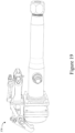
- the catcher insert 348 can include a threaded retaining bolt 349 at a proximal end and a latching element 351 (e.g., a ball, a roller, a cylinder, a cam, and the like) at distal end that is configured to engage, and latch to, a pumped out core tube assembly that is pumped from a distal end of the drill string to the catcher insert 348.
- a latching element 351 e.g., a ball, a roller, a cylinder, a cam, and the like
- This is in contrast to a pump-in wireline overshot 346 that is pumped to a core tube assembly and coupled to the core tube assembly, and the core tube assembly and wireline overshot are retrieved via wireline as a coupled pair.
- an exemplary pump-in wireline overshot 346 can include the overshot assembly of the ROLLER LATCH QUICK PUMP-IN head assembly (the overshot itself referred to separately as the QUICK PUMP-IN OVERSHOT) manufactured by BOART LONGYEAR and disclosed in, for example, U.S. Patent No. 9,328,608 .
- One embodiment of the catcher insert 348 can comprise features of the catcher insert of the HYDROSHOT reverse circulation overshot manufactured by BOART LONGYEAR.
- International Application No. PCT/US2018/017949 to Drenth et al., filed February 13, 2018 , discloses a reverse circulation core tube assembly and aspects thereof that can be implemented with embodiments of the drilling system 200 as disclosed herein.
- the structure of the disclosed catcher insert can generally correspond to the distal portion of an overshot subassembly as disclosed in International Application No. PCT/US2018/017949 .
- the catcher insert can comprise a latch assembly.
- the latch assembly can comprise at least one latch member (optionally, a plurality of latch members). It is contemplated that each latch member of the at least one latch member can be at least one of a ball, a roller, a cylinder, a cam-shaped element, and the like.
- the latching assembly can be configured for movement about and between a retracted position and a deployed position.
- the latch member is a ball detent.
- a distal portion of the latch assembly can be axially movable and spring-biased in a distal direction with respect to an inner portion.
- the inner portion of the latch assembly can define a groove that is tapered in a proximal direction so that proximal movement of the distal portion can allow the ball detent to move radially inwardly.
- the distal portion of the latch assembly can be driven proximally so that the ball detent can move radially inwardly.
- the distal portion of the latch assembly can then be received within the reverse circulation overshot.
- the applied force to the distal portion of the latch assembly can decrease so that the spring bias can cause the distal portion of the latch assembly to move distally, thereby moving the ball detent to the deployed position.
- any conventional latch mechanism can be used to effect locking engagement between the catcher insert and the head subassembly.
- the overshot assembly can include a main body coupled to pulling dogs for movement between an inner tube assembly coupling position and a release position.
- the overshot can include an annular seal for forming a fluid seal with the interior of a drill string.
- An elongated overshot tube can be joined to the main body and valving mechanism resiliently urged to block axial outward flow through the overshot tube.
- An overshot adaptor can include a valving mechanism to permit fluid to be pumped inwardly through the overshot adaptor and the overshot tube and block fluid flow in the opposite direction.
- a front end of the overshot loading assembly 342 can comprise a seal housing 350 with seals 352 therein.
- the second head assembly 300 can be driven forward so that the seals 352 engage a proximal end of the drill string 150 to fluidly seal the overshot loading assembly to the drill string.
- the overshot loading assembly 340 can include a fluid port 354 that can receive a pressurized fluid (e.g., water). When the overshot loading assembly 340 is sealingly engaged with the drill string 150, the pressurized fluid can pump the overshot tool 344 toward the distal end of the drill string.
- a pressurized fluid e.g., water
- a rear end of the overshot loading assembly 340 can include a wireline seal 360 attached via a nut 362.
- the wireline seal 360 and nut 362 can each comprise an axial through-hole that can be sized and otherwise configured to allow a cable of a quick release cable connection 364, as is known in the art, to pass therethrough.
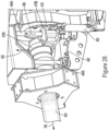
- the overshot loading assembly 340 can further comprise an overshot releaser 370.
- the overshot releaser 370 can comprise a lever 372 having a forked first end 374 and a hydraulic piston 376 at an opposite second end that actuates to pivot the lever about its pivotal axis 378.
- the overshot release lever 372 can be used to delatch the wireline overshot 346 or catcher insert 348 from a core tube assembly 188 after it has been retrieved from a distal end of the drill string.
- the forked first end 374 of the lever 372 can pivot toward the overshot loading assembly's axis and engage an annular ridge 380 of the overshot tool 344.
- Figure 24 illustrates a first step of the overshot releasing method, in which the overshot releaser 370 is in a configuration prior to engagement with the overshot tool 344.
- Figure 25 illustrates a second step of the overshot releasing method, in which the overshot releaser 370 is engaging the overshot tool 344.
- Figure 26 illustrates a third step in the overshot releasing method, in which the core tube assembly 188 has been released from the overshot tool 344.
- a casing pipe 400 can be used to anchor the drill rig 100 to the foundation 165. Although disclosed below with reference to drill rig 100, it is contemplated that the disclosed anchoring systems and methods can be used to anchor any known or conventional underground drill rig. Optionally, it is contemplated that the disclosed anchoring systems can be retrofit to an existing rig.
- a first bore having a first diameter can be drilled into the formation 165. The first diameter can be sufficient to receive the casing pipe 400.
- a drill bit 500 as shown in Figures 35-39 can be used to drill said first bore.
- the drill bit 500 can be a core-sampling drill bit with axially-tapered waterways according to an implementation of the present invention.
- the drill bit 500 can include a shank or blank 502, which can be configured to connect the drill bit 500 to a component of the drill string 150 ( Figure 1 ).
- the drill bit 500 can also include a cutting portion or crown 504.
- the drill bit 500 can be an impregnated drill bit that includes abrasive cutting elements (e.g., diamond or synthetic diamond) within a matrix that is configured to wear away to continually expose the cutting elements during the life of the bit.
- abrasive cutting elements e.g., diamond or synthetic diamond
- the drill bit 500 can define an interior space about its central axis 506 for receiving a core sample.
- both the shank 502 and crown 504 can have a generally annular shape defined by an inner surface 507 and outer surface 508. Accordingly, pieces of the material being drilled (e.g., core) can pass through the interior space of the drill bit 500 and up through an attached drill string.
- the drill bit 500 may be any size, and therefore, may be used to collect core samples of any size. While the drill bit 500 may have any diameter and may be used to remove and collect core samples with any desired diameter, the diameter of the drill bit 500 can range in some implementations from about 2.54 cm (1 inch) to about 30.48 cm (12 inches).
- the kerf of the drill bit 500 may be any width, according to some implementations the kerf can range from about 0.66 cm (1 ⁇ 4 inches) to about 15.24 cm (6 inches).
- the crown 504 can be configured to cut or drill the desired materials during the drilling process.
- the crown 504 of the drill bit 500 can include a cutting face 509.
- the drill bit 500 can be a stepped drill bit, having a first cutting face 509A between the drill bit's central axis 506 and a first radius 530 and a second cutting face 509B outside of the first radius 530.
- the first cutting face 509A can be spaced from the second cutting face in a distal direction.
- the cutting face 509 can be configured to drill or cut material as the drill bit 500 is rotated and advanced into a formation.
- the cutting face 509 can comprise a plurality of projections 520.
- the projections 520 can comprise the same material that forms the cutting face 509.
- the projections 520 and the cutting face 509 can both comprise the same matrix material, which optionally includes impregnated abrasive cutting media.
- Exemplary configurations and characteristics of the projections 520 are further disclosed in U.S. Patent No. 9,637,980 .
- the cutting face 509 can also include waterways that may allow drilling fluid or other lubricants to flow across the cutting face 509 to help provide cooling during drilling.
- the crown 504 can include a plurality of notches 512 that extend from the cutting face 509 in a generally axial direction into the crown 504 of the drill bit 500. Additionally, some notches 512 can extend from the inner surface 507 of the crown 504 to the outer surface 508 of the crown 504. In these aspects, the notches 512 can extend through the radial thickness of both the first and second cutting faces 509A, 509B. As waterways, the notches 512 can allow drilling fluid to flow from the inner surface 507 of the crown 504 to the outer surface 508 of the crown 504.
- the notches 512 can allow drilling fluid to flush cuttings and debris from the inner surface 507 to the outer surface 508 of the drill bit 500, and also provide cooling to the cutting face 509.
- the drill bit can further comprise notches 512A that only extend through the radial thickness of the second cutting face 509B. It is contemplated that these notches 512A can be circumferentially offset from the notches 512 that extend through both the first and second cutting faces 509A, 509B.
- the crown 504 may have any number of notches that provides the desired amount of fluid/debris flow and also allows the crown 504 to maintain the structural integrity needed.
- Figures 36 and 38 illustrate that the drill bit 500 includes six notches 512.
- the drill bit 500 can include as few as one notch or as many 20 or more notches, depending on the desired configuration and the formation to be drilled.
- the notches 512 may be evenly or unevenly spaced around the circumference of the crown 504.
- Figure 38 depicts six notches 512, wherein three notches extend to the first face 509A, and three notches are axially spaced from the first cutting face 509A.
- each triplet of notches are evenly spaced from each other about the circumference of the crown 504, and the triplets of notches are rotationally offset from each other.
- the notches 512 can be staggered or otherwise not evenly spaced.
- Each of the notches 512 can be axially and radially tapered.
- the notches 512 can have an increasing cross sectional width and height in from the inner surface 507 to the outer surface 508.
- the first bore hole can be drilled while the drill rig 100 is not anchored. Accordingly, the first bore can be drilled using a relatively low axial pressure of the drill bit against the formation 165.
- the axial pressure can be low enough that the frictional force between the drilling system 200 and the ground holds the drill rig in place when drilling the first bore.
- the drill rig 100 can then insert the casing pipe 400 into the first bore.
- the first head assembly 110 can have jaws that have sufficient radial travel to grip the outer diameter of the casing pipe 400.
- the rod holder 172 can similarly have jaws with sufficient radial travel to grip the outer diameter of the casing pipe 400.
- the casing pipe 400 can have a binder 402 in a capsule at the front of the casing pipe or on an exterior surface.
- the binder 400 can be, for example, a plurality of resin sticks. Once the casing pipe 400 is inserted into the first bore, the binder can set to grip the wall of the first bore. It is contemplated that the method of anchoring the drill rig 100 can require a step of waiting for the binder 402 to set before proceeding.
- adhesive tubes 900 can be inserted into the casing pipe 400 (e.g., during setup of the drill rig).
- a plug 902 can be disposed proximally of the adhesive tubes 900 within the casing pipe 400.
- the first casing pipe can be inserted into the drilled bore hole.
- the second head 300 can couple to the casing pipe 400 and apply water pressure to the casing pipe 400 to force the plug 902 distally, thereby forcing the adhesive in the adhesive tubes into the annulus between the casing pipe 400 and the bore hole wall.
- the drill rig can then be anchored to the casing pipe.
- the casing pipe 400 can comprise a generally cylindrical tubular member having a central axis 404.
- the casing pipe 400 can be secured to an anchoring nut 412.
- the anchoring nut 412 can comprise a gripping feature 414.
- the anchoring nut 412 can be welded to the casing pipe 400.
- a single monolithic, unitary body can comprise the casing pipe 400 and the anchoring nut 412.
- the casing pipe and anchoring nut can be cast as a single component.
- the casing pipe 400 and anchoring nut 412 can be collectively embodied as a cylindrical tube having a gripping feature 414 thereon.
- the gripping feature 414 can comprise a pair of spaced annular ribs 416 that extend radially from the anchoring nut 412.
- the spaced annular ribs can have opposing faces 418 that slope toward each other from a farthest radial edge toward the central axis 404 of the casing pipe.
- the gripping feature can comprise an annulus that is tapered in a radially inward direction.
- the taper can be at a selected angle from a radial axis that extends perpendicularly from the anchoring nut. It is contemplated that the selected angle can range from about 10 degrees to about 45 degrees or from about 15 degrees to about 40 degrees.
- the selected angle can be about 30 degrees.
- a clamp 420 can engage the gripping feature 414 of the anchoring nut 412.
- the clamp 420 can be configured to attach to the drill rig 100 via a bracket 410.
- the clamp 420 can be integral to the drill rig 100.
- the clamp 420 can have a plurality of jaws 422 (e.g., three jaws, as shown) that are configured to move axially from a central axis 424.
- the jaws 422 can be hydraulically actuated.
- Each jaw 422 can comprise a complementary shape to be received within the gripping feature 414.
- each jaw 422 can comprise, in cross section in a longitudinal plane including the central axis 424 of the clamp 420, a complementary shape to that of a cross section of the gripping feature 414 in the same plane.
- the clamp jaws can have an inner radius that is equal to the outer radius of the gripping feature in the same transverse plane.
- an end of the anchoring nut 412 opposite the casing pipe 400 can comprise one or more female threads to receive male threads 403 of a drive rod 405.
- the drive rod 405 can be used to push the casing into the first bore.
- the drive rod can couple to the anchoring nut via a bayonet coupling.
- the drive rod 405 (or extension rod) can comprise a female bayonet head that is configured to engage a male bayonet head of the anchoring nut.
- the male and female components can be reversed so that the drive rod comprises the male bayonet head, and the anchoring nut can comprise a female bayonet head. In this way, the drive rod 405 can releasably couple to the casing pipe.
- a pump-out core tube can be used to retrieve a core sample from a distal end of the drill string.
- high pressure water or other fluid
- a seal can be made between the casing and the drill string in order to direct pumped-in water down the bore (i.e. away from the drill rig).
- a seal casing gland 450 can attach to the anchoring nut 412 at an end of the anchoring nut 412 opposite the casing pipe 400.
- the seal casing gland 450 can be configured to create a seal between the casing pipe 400 and an outer surface of the drill string 150.
- the seal casing gland can comprise a front end 452 that is configured to seal against the anchoring nut 412.
- the seal casing gland 450 can define an annular lip 454 against which the anchoring nut can abut.
- An annular groove 456 can receive a seal therein for sealing against an exterior circumferential surface of the anchoring nut.
- the seal casing gland 450 can comprise an annular bladder 460 comprising rubber or another flexible material.
- the annular bladder 460 can receive water (or other fluid) therein from a first hose connection 462.
- the bladder Upon receiving water in the annular bladder 460, the bladder can inflate to seal against an exterior surface of the drill string 150.
- Water can then be pumped into the seal casing gland through a second water connection 466. Because of the seal between the seal casing gland and the drill string, the water pumped in through the second hose connection 466 is directed down the bore and ultimately applying fluid pressure against the pump-out core tube that pumps the core tube through the drill string to its proximal end, where the catcher insert 348 ( Figure 23 ) can engage the core tube.
- a rear end 470 of the seal casing gland 450 can include a bearing 472 that can engage an outer surface of the drill rod 140, thereby acting as a rod guide.
- a seal 474 can mount to the bearing to seal in drilling fluid that returns through the annulus between the drill string and the bore.
- a third hose connection 476 can be in communication with the annulus between the drill string 150 and the seal casing gland and provide an outlet for returning drilling fluid.
- the seal casing gland 450 can optionally have an inner diameter that is less than the outer diameter of the casing pipe 400. Therefore, the seal casing gland 450 can be moved from the drilling axis of the rig prior to and during insertion of the casing pipe 400. For example, the seal casing gland 450 can be pivoted away from the longitudinal drilling axis 180 as the first bore is being drilled and casing pipe is being positioned in the first bore. Once the casing pipe 400 is anchored to the formation, the seal casing gland 450 can be engaged with the anchoring nut.
- the seal casing gland 450 can be pivotable with respect to the clamp to move the seal casing gland 450 from a stowed position that is away from the drilling axis to an engaged positon in which the seal casing gland 450 is engaged with the anchoring nut and aligned with the longitudinal drilling axis.
- the seal casing gland 450 can pivotably attach to a bracket 478.
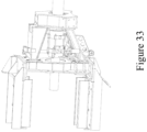
- Figures 27 and 29-33 illustrate a first example
- Figure 28 illustrates a second, alternative example of a seal casing gland movement assembly.
- the bracket can comprise a first portion 478A that attaches to the casing gland 450 and a second portion 478B that is pivotably coupled to the first portion 278A.
- the bracket 478 can be slidable along a pair of rails 484A, 484B.
- the first portion 478A of the bracket 478 can pivotably attach to the rail 484A about an axis 486. Accordingly, the bracket's first portion 478A can be pivotable with respect to the bracket's second portion 478B.
- a first actuator 488 which, can be a hydraulic cylinder, can be actuated from a retracted position, in which the seal casing gland 450 is in an intermediate position that is spaced from the anchoring nut 412, to an extended position, in which the seal casing gland 450 is in the engaged position and is engaged with the anchoring nut 412.
- second actuator 490 e.g., a hydraulic cylinder
- first actuator 488 When the first actuator 488 is in the retracted position so that the seal casing gland is disengaged and spaced from the anchoring nut (to the right in Figure 28 ), second actuator 490 (e.g., a hydraulic cylinder) can move from a retracted position to an extended position, thereby sliding the bracket 478 vertically (upward in the Figures) along the rails.
- the seal casing gland 450 can be moved to a stowed position that is sufficiently spaced from the drill rig's longitudinal drilling axis 180 so that the seal casing gland 450 does not interfere with drilling and placement of the casing pipe 400.
- the second actuator 490 can retract, thereby sliding the bracket 478 downward so that the seal casing gland 450 is in the intermediate position.
- the first actuator 488 can then extend to cause the seal casing gland 480 to engage the anchoring nut 412.
- the seal casing gland 450 is pivotably connected to the bracket 478 about an axis 482 (as in Figure 28 ) or otherwise loosely connected to the bracket 478 to allow slight pivotal movement (as in the first embodiment) so that while the bracket's first portion 478A continues to pivot as the seal casing gland moves from the intermediate position to the engaged position, the seal casing gland can stay axially aligned with the anchoring nut.
- a gland 700 can be configured to have a sufficient diameter for the casing 400 and the anchor nut 412 to pass therethrough.
- the gland 700 can attach to the frame (e.g., to the bracket 410 in Figure 29 ) via a bracket 702.
- the gland can comprise an annular seal 704 that is rotatably coupled at a first end 705 to the bracket 702 via a thrust bearing 706 so that the annular seal 704 can rotate with the drill string.
- a second end 707 of the annular seal 704 can be movable relative to the first end 705.
- the distal end 707 of the annular seal 704 can couple to an actuator 708 (e.g., a clutch fork driven via a hydraulic cylinder (not shown)) along the drilling axis.
- the actuator 708 can be selectively moved relative to the bracket about and between a plurality of positions to permit modification of the position of the first end 705 of the annular seal (and, thus, the operative length and the corresponding operative diameter of the annular seal).
- the gland can further comprise a port 709 that is forward of (closer to the distal end of the drill string than) the annular seal 704 and can provide fluid communication to the interior of the gland.
- annular seal 704 and the entire gland 700 can define a first inner diameter 712 through which the casing 400 and anchoring nut 412 can pass therethrough.
- the bracket 702 can house a seal 714 for engaging the anchoring nut 412.
- the annular seal 704 can define a second inner diameter 718 that gently engages the drill rod. In this way, fluid can be pumped into the drill rod and the returning slurry can return through the annulus between the drill string and the casing and exit the port 709.
- a third position 718 see, for example, FIG.
- the annular seal 704 can apply a sufficient pressure against the drill string to cause fluid pumped into port 709 to travel distally down the annulus between the casing and the drill string in order to pump a reverse-circulation overshot (e.g., a HYDROSHOT reverse-circulation overshot) proximally within the drill string (and, eventually, out of the drill string).
- a reverse-circulation overshot e.g., a HYDROSHOT reverse-circulation overshot
- the actuator 708 When the actuator 708 is in the first position 710, the actuator can bias against a distal lip of the gland; when the actuator is in the third position 718, the actuator can bias against a proximal lip of the gland; and when the actuator is in the second position 716, the actuator can bias against neither the proximal nor distal lip.
- the annular seal 704 can naturally (without compression or tension) bias against the drill string.
- the anchoring nut 412 can be integrally formed with, or otherwise coupled to, a gland 750.
- the gland 750 can define the pair of spaced annular ribs 416 that extend radially from the gland 750.
- the gland 750 can couple to the proximal casing (e.g., via a threaded coupling 752). This can contrast with the gland 450 that is coupled to the rig 100 and shifts and pivots in and out of engagement with the casing.
- the gland 750 can be coupled to a proximal-most casing pipe prior to coupling the proximal-most casing pipe to casing pipe string.
- the gland 750 can be coupled to the proximal-most casing pipe after it has been coupled to the string of casing pipes.
- the gland 750 can comprise an annular bladder 460 that can be inflated to bias against the drill string as disclosed herein with reference to the gland 450.
- the gland 750 can further comprise one or more seals 474 that are rotatably attached to the gland 750 for engaging and rotating with the drill string.
- the gland 750 can define a male bayonet coupling 754.
- the gland 750 can couple to a collar fitting 755 that defines the male bayonet coupling 754).
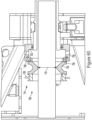
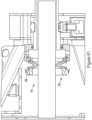
- the male bayonet coupling 754 can couple to the female bayonet coupling 756 of the extension rod ( FIG. 57 ).
- the female bayonet coupling can be on a bayonet head 760 that is axially movable with respect to a main body 762 of the extension rod 405.
- the bayonet head 760 can be biased in a first longitudinal direction with a first spring 762 and a second, opposite longitudinal direction 764 via a second spring 764 in order to assist with axial alignment and prevent damage to engaging components during coupling and decoupling.
- fluid can be provided to pump a reverse-circulation overshot proximally in a drill string. Further, when providing drilling fluid during drilling, it can be desirable to direct the drilling fluid that is returning through the annulus between the drill string and the bore to an outlet (e.g., an outlet in the gland) so that the returning drilling fluid and formation pieces can be.
- an outlet e.g., an outlet in the gland
- At least one of the jaws 422 of the clamp 420 can define a first fluid port 770, and a corresponding first fluid port 772 of the gland 750 can be angularly and axially aligned with the first fluid port 770 to define fluid communication between the first fluid port 770 of the jaw 422 and the first fluid port 772 of the gland 750.
- the fluid port 770 can provide an outlet for lubricant fluid during drilling and an inlet for fluid for pumping out a reverse-circulation drilling assembly.
- a first ring seal 774 (e.g., an O-ring) can seal the fluid communication between the jaw 422 and the gland 750.
- a second fluid port 776 of the jaw 422 can align with a second fluid port 777 in the gland 750 for providing fluid communication to inflate and deflate the annular seal for respective engagement and disengagement from the drill string.
- a second ring seal 778 can seal the fluid communication between the second fluid port 776 in the jaw 422 422 and the second fluid port 777 in the gland 750.
- a front ring plate 780 can define a front stop that inhibits further axial movement in the distal direction.
- the front ring plate 780 can define a taper 782 that mates with a front-end taper 784 of the gland 750.
- At least one of the jaws 422 can comprise one or more spring pins 786 that are spring-biased radially outward.
- the spring pins 786 can be received within respective grooves 788 that define stops 790 at select angular positions so that engagement between the spring pins 786 engage the stops 790 corresponds to angular alignment between the fluid ports of the jaw 422 and the fluid ports of the gland 450.
- the grooves 788 can have a decreasing depth in an angular direction so that rotation of the gland 750 in said angular direction can enable the spring pins 786 to be released from the grooves 788.
- a port hub 800 can provide fluid communication to the first fluid port 770 and second fluid port 777 in the gland 750.
- the port hub 800 can define a first annulus 802 for axial alignment with the first fluid port 770 and a second annulus 804 that axially aligns with the second fluid port 777.
- the gland 750 can comprise three seals 806 for sealing against the port hub 800 (e.g., with a first seal and a second seal positioned on opposite sides of the first annulus 802, and the second seal and a third seal positioned on opposite sides of the second annulus 804).
- a first inlet/outlet 808 can provide fluid communication into the first annulus 802, and a second inlet/outlet 810 can provide fluid communication to the second annulus 804.
- the drilling system 200 can be configured to perform some or all drilling aspects without physical interaction between the drilling system 200 and a human operator (i.e., in a hands-free manner). That is, an operator need not touch the mechanical components of the drilling system 200 as the first (anchoring) bore is being drilled, as the drill rig is being anchored to the foundation 165, during subsequent drilling, or during core retrieval. It should be understood that an operator may still remotely control aspects of the drilling process. In various embodiments, control of the drilling system can be partially or wholly controlled by a computing device, as further disclosed herein.
- a first method can include fitting a core barrel with the drill bit 500 that is sized to create the first bore (i.e. of a sufficient diameter to receive the casing pipe 400).
- the drilling system 200 can use the drill bit 500 to drill the first bore.
- the drilling system 200 can then remove the drill bit 500 and core barrel from the first bore (e.g., using the drill string component removal methods as described herein).
- the casing pipe and anchoring nut can be loaded onto the drill rig 100, and, according to some aspects, gripped by the rod holder 172.
- the rod handler 210 can position the casing pipe so that the first head assembly 110 can grip the casing pipe, and the first head assembly 110 can then position the casing pipe in the rod holder 172.
- a drive rod can be loaded onto the drill rig 100 and screwed into the thread(s) of the anchoring nut.
- the second head can be screwed into the back of the drive rod.
- the second head can then thread the drive rod into the casing pipe 400 while the rod holder 172 grips the casing pipe.
- the first head assembly 110 can thread the drive rod into the casing pipe 400 as the rod holder 172 holds the casing pipe.
- the first head assembly 110 can grip the drive rod and insert the casing pipe into the first bore.
- the first method can include a step of waiting for the binder 402 on the casing pipe 400 to cure.
- the drive rod can then be unscrewed (or otherwise decoupled, for example, by decoupling the bayonet coupling) from the casing pipe 400 via the first head assembly 110 and removed from the drill rig 100.
- the clamp 420 can anchor to the anchoring nut 412.
- the entirety of the first method can be performed without physical interaction of a human operator.
- the first method can further comprise the steps of: before using the drill bit 500 to drill the first bore, moving the seal casing gland 450 to the stowed position; and after anchoring the clamp 420 to the anchoring nut 412, moving the seal casing gland 450 to the engaged position.
- the drilling system 200 can be used to add drill rods (or other drill string components) to the drill string 150.
- the second head assembly can be retracted toward the rear portion of the drill rig 100 and away from the drill string 150 to permit receipt of the first drill string component.
- the drill rig 100 can then receive the first drill string component from the rod handler 210.
- the drill rig 100 can move the second head assembly 300 forward until the male thread(s) of the spindle 304 engage the female thread(s) of the first drill string component 140.
- the second head may continue to move past the point of engagement between the male thread(s) of the spindle 304 and the female thread(s) of the first drill string component to compress spring 306 by a distance so that as the first drill string component 140 and spindle 304 are threadedly coupled, the spindle 304 can float to take up the axial movement of threading.
- the second method can be performed in conjunction with the first method (such as, for example, after completion of the first method).
- a range detector or load sensor can be used to detect engagement between respective components, such as the drill rod 140 and the drill string 150.
- the drill rig 100 can use one or more of the following: a displacement of the spindle float relative to the second head; the movement of the second head assembly with respect to the feedframe; a hydraulic pressure driving the motor 320, and the amount of rotation of the spindle 304 and/or first head 110.
- the computing device can determine the number of turns made and the axial distance moved to determine if the threading is completed.
- the computing device can determine that the threaded coupling is tight and correctly threaded. If the hydraulic pressure rises before the expected number of turns and/or before the distance moved is sufficient, the computing device can determine that the threaded coupling is jammed. If the hydraulic pressure does not rise when expected, the computing device can determine that the respective threads are not engaged.
- the motor can rotate the spindle backwards (in a decoupling direction) until the spindle moves forward one thread pitch, thereby indicating a rotational position at which the respective threads are rotationally aligned.
- the computing device can store this rotational position as a starting position when determining the number of rotations for threading respective components.
- the motor 320 can then rotate the spindle 304 to threadedly couple the spindle to the first drill string component 140.
- the second head assembly 300 can then move forward via the feedframe until the male thread(s) of the drill string component engage the female thread(s) of the drill string. Similarly, the second head can move past mere contact and compress the spring 306 as the spindle 304 floats to enable travel as the drill string and drill string component are threadedly engaged. Similarly to when coupling the spindle to the drill rod 140, the motor can rotate the spindle backwards (in a decoupling direction) until the spindle moves forward one thread pitch, thereby indicating a position at which the respective threads are rotationally aligned.
- the motor 320 can then rotate the spindle 304 forwards, thereby rotating the drill string component to thread the drill string component's male thread(s) in to the drill string's female thread(s).
- the hydraulic clutch can then decouple the motor 320 from the spindle 304.
- the first head assembly can then rotate the drill string comprising the first drill string component at a drilling speed.
- the spindle 304 can stay connected and thus be used to provide drilling fluid from the water swivel to the interior bore of the drill string 150.
- the second head assembly 300 can be used to push the drill string into the bore.
- the drilling system 200 can be used to the remove a drill string component from a drill string.
- the feedframe 105 can move the second head assembly 300 toward the front portion of the drill rig until the male thread(s) of the spindle engages the female thread(s) of the drill string.
- the motor 320 can rotate the spindle to threadedly couple the spindle to a first drill rod of the drill string that is at a proximal end of the drill string.
- the second head assembly can move toward the rear portion of the drill rig to draw the drill string rearward until a second drill string component that is distal of the first drill string component is received with in the rod holder.
- the rod holder can grip the second drill string component, and the first head assembly can then rotate the first drill string component to unscrew the first drill string component from the rest of the drill string.
- the rod handler can then grab the first drill string component and hold it stationary while the motor 320 rotates the spindle to decouple the spindle from the first drill string component.
- the rod handler can then remove the first drill string component from the drill rig.
- the third method can be used in conjunction with the first and/or second methods (such as, for example, after completion of the first and/or second methods).
- the drilling system 200 can be used to retrieve a core tube assembly using wireline.
- the rod holder can grip the proximal drill string component of the drill string.
- the motor 320 can rotate the spindle 304 to decouple the spindle from the drill string.
- the actuator 330 can move a portion of the second head assembly 300 to align the overshot loading assembly 340 with the longitudinal drilling axis 180 of the drill rig 100.
- a water pump can then pump the overshot 346 from the overshot loading chamber until it engages the core tube assembly 188.
- the wireline winch 190 can retract the core tube assembly 188 until the overshot 346 is received in the overshot loading assembly.
- the feedframe 105 can then move the second head assembly 300 toward the rear portion 184 of the drill rig 100 until the core tube assembly 188 is removed entirely from the drill string 150.
- the rod handler 210 can then grip the core tube assembly 188.
- the overshot releaser 370 can then decouple the overshot 346 from the core tube assembly 188.
- the rod handler 210 can then remove the core tube assembly 188 from the drill rig 100.
- the fourth method can be used in conjunction with one or more of the first, second, and third methods (such as, for example and without limitation, after completion of the first and/or second methods).
- the drilling system 200 can use the rod handler 210 to insert an empty core tube assembly 188 into the drill string 150.
- the rod handler 210 can insert the empty core tube about one meter deep into the drill string 150.
- the feedframe 105 can move the second head assembly toward the front portion 182 of the drill rig 100 until the overshot engages the empty core tube assembly.
- the rod handler 210 can then disengage from the empty core tube assembly 188.
- the feedframe 105 can move the second head assembly 300 toward the front portion of the drill rig to further insert the empty core tube assembly 188 into the drill string 150.
- the overshot releaser 370 can then disengage the overshot from the empty core tube assembly 188.
- the feedframe 105 can then move the second head assembly 300 toward the rear portion of the drill rig until the second head portion has sufficient room to shift.
- the actuator 330 can the shift the second head assembly 300 so that the spindle 304 is aligned with the longitudinal drilling axis 180 of the drill rig 100.
- the motor 320 can rotate the spindle so that the spindle 304 threadedly engages the end of the drill string 150.
- the clutch can disengage the motor 320 from the spindle.
- a pump can pump the empty core tube assembly 188 to the distal end of the drill string.
- the first head assembly 110 can then grip the drill string 150 to commence drilling.
- the fifth method can be used in conjunction with one or more of the first, second, third, and fourth methods (such as, for example and without limitation, after completion of the first, second, third, or fourth method).
- the second head assembly 300 can be configured to float freely (i.e., slide axially along the feedframe) with the drill string as the first head 110 drives the drill string along the longitudinal drilling axis.
- a hydraulic valve can be energized to allow hydraulic fluid to flow in and out of the hydraulic cylinders of the feedframe that move the second head.
- the drill rig can use both the first head assembly 110 and the second head assembly 300 to pull on the drill string, for example to dislodge a stuck drill string 150.
- the first head assembly 110 can engage the drill string.
- the motor 320 can rotate the spindle to threadedly couple the spindle 304 of the second head assembly 300 to the drill string 150.
- the feedframe 105 can simultaneously drive the first head assembly 110 and the second head assembly 300 toward the rear portion 184 of the drill rig 100.
- the sixth method can be used in conjunction with one or more of the first, second, third, fourth, and fifth methods (such as, for example and without limitation, after completion of the first, second, third, fourth, or fifth method).
- the drill rig can insert an empty core tube assembly in an alternative way.
- the second head assembly 300 can be sufficiently retracted.
- the rod handler can position the core tube assembly in line with the longitudinal drilling axis.
- the first head assembly can be moved so that the centralizer 111 can engage the second head assembly, and the centralizer can grip a front end of the core tube assembly.
- the second head assembly can be moved forward until the overshot engages a socket at the rear of the core tube assembly.
- the rod handler can then disengage from the core tube assembly.
- the second head assembly can move forward to insert the core tube assembly into the drill string.
- the seventh method can be used in conjunction with one or more of the first, second, third, fourth, and sixth methods (such as, for example and without limitation, after completion of the first, second, third, fourth, or sixth method).
- FIG. 40 shows an exemplary computing system 1000 that can be configured to control operation of various aspects of the drilling system 200, including coordinating movement of the first head assembly and second head assembly, controlling the drilling feed rate, and operation of various components discussed herein.
- Computing system 1000 can include a computing device 1001 and a display 1011 in electronic communication with the computing device, which can be any conventional computing device, such as, for example and without limitation, a personal computer, computing station (e.g., workstation), portable computer (e.g., laptop, mobile phone, tablet device), smart device (e.g., smartphone, smart watch, activity tracker, smart apparel, smart accessory), security and/or monitoring device, a server, a router, a network computer, a peer device, edge device or other common network node, and so on.
- computing station e.g., workstation
- portable computer e.g., laptop, mobile phone, tablet device
- smart device e.g., smartphone, smart watch, activity tracker, smart apparel, smart accessory
- security and/or monitoring device
- a smart phone, tablet, or computer can comprise both the computing device 1001 and the display 1011.
- the display 1011 can be provided as a separate component from the computing device 1001.
- the display 1011 can be in wireless communication with the computing device 1001, thereby allowing usage of the display 1011 in a manner consistent with that of the display of the smartphone as disclosed herein.
- the computing device 1001 may comprise one or more processors 1003, a system memory 1012, and a bus 1013 that couples various components of the computing device 1001 including the one or more processors 1003 to the system memory 1012. In the case of multiple processors 1003, the computing device 1001 may utilize parallel computing.
- the bus 1013 may comprise one or more of several possible types of bus structures, such as a memory bus, memory controller, a peripheral bus, an accelerated graphics port, and a processor or local bus using any of a variety of bus architectures.
- the computing device 1001 may operate on and/or comprise a variety of computer readable media (e.g., non-transitory).
- Computer readable media may be any available media that is accessible by the computing device 1001 and comprises, non-transitory, volatile and/or non-volatile media, removable and non-removable media.
- the system memory 1012 has computer readable media in the form of volatile memory, such as random access memory (RAM), and/or non-volatile memory, such as read only memory (ROM).
- the system memory 1012 may store data such as mesh computation data 1007 and/or program modules such as operating system 1005 and drilling control software 1006 that are accessible to and/or are operated on by the one or more processors 1003.
- the computing device 1001 may also comprise other removable/non-removable, volatile/non-volatile computer storage media.
- a mass storage device 1004 may provide non-volatile storage of computer code, computer readable instructions, data structures, program modules, and other data for the computing device 1001.
- the mass storage device 1004 may be a hard disk, a removable magnetic disk, a removable optical disk, magnetic cassettes or other magnetic storage devices, flash memory cards, CD-ROM, digital versatile disks (DVD) or other optical storage, random access memories (RAM), read only memories (ROM), electrically erasable programmable read-only memory (EEPROM), and the like.
- Any number of program modules may be stored on the mass storage device 1004.
- An operating system 1005 and the drilling control software 1006 may be stored on the mass storage device 1004.
- One or more of the operating system 1005 and the drilling control software 1006 (or some combination thereof) may comprise program modules and the drilling control software 1006.
- Drilling control data 1007 may also be stored on the mass storage device 1004.
- the drilling control data 1007 may be stored in any of one or more databases known in the art.
- the databases may be centralized or distributed across multiple locations within the network 1015.
- a user may enter commands and information into the computing device 1001 via an input device (not shown).
- input devices comprise, but are not limited to, a keyboard, pointing device (e.g., a computer mouse, remote control), a microphone, a joystick, a scanner, tactile input devices such as gloves, and other body coverings, motion sensor, and the like
- a human machine interface 1002 that is coupled to the bus 1013, but may be connected by other interface and bus structures, such as a parallel port, game port, an IEEE 1394 Port (also known as a Firewire port), a serial port, network adapter 1008, and/or a universal serial bus (USB).
- a display 1011 may also be connected to the bus 1013 via an interface, such as a display adapter 1009. It is contemplated that the computing device 1001 may have more than one display adapter 1009 and the computing device 1001 may have more than one display 1011.
- a display 1011 may be a monitor, an LCD (Liquid Crystal Display), light emitting diode (LED) display, television, smart lens, smart glass, and/ or a projector.
- other output peripheral devices may comprise components such as speakers (not shown) and a printer (not shown) which may be connected to the computing device 1001 via Input/Output Interface 1010. Any step and/or result of the methods may be output (or caused to be output) in any form to an output device.
- Such output may be any form of visual representation, including, but not limited to, textual, graphical, animation, audio, tactile, and the like.
- the display 1011 and computing device 1001 may be part of one device, or separate devices.
- the computing device 1001 may operate in a networked environment using logical connections to one or more remote computing devices 1014a,b,c.
- a remote computing device 1014a,b,c may be a personal computer, computing station (e.g., workstation), portable computer (e.g., laptop, mobile phone, tablet device), smart device (e.g., smartphone, smart watch, activity tracker, smart apparel, smart accessory), security and/or monitoring device, a server, a router, a network computer, a peer device, edge device or other common network node, and so on.
- Logical connections between the computing device 1001 and a remote computing device 1014a,b,c may be made via a network 1015, such as a local area network (LAN) and/or a general wide area network (WAN). Such network connections may be through a network adapter 1008.
- a network adapter 1008 may be implemented in both wired and wireless environments. Such networking environments are conventional and commonplace in dwellings, offices, enterprise-wide computer networks, intranets, and the Internet.
- the computing device 1001 can be in communication with the remote computing devices 1014a,b,c through a Cloud-based network.
- Application programs and other executable program components such as the operating system 1005 are shown herein as discrete blocks, although it is recognized that such programs and components may reside at various times in different storage components of the computing device 1001, and are executed by the one or more processors 1003 of the computing device 1001.
- An implementation of the drilling control software 1006 may be stored on or sent across some form of computer readable media. Any of the disclosed methods may be performed by processor-executable instructions embodied on computer readable media.
Landscapes
- Engineering & Computer Science (AREA)
- Life Sciences & Earth Sciences (AREA)
- Geology (AREA)
- Mining & Mineral Resources (AREA)
- Physics & Mathematics (AREA)
- Environmental & Geological Engineering (AREA)
- Fluid Mechanics (AREA)
- General Life Sciences & Earth Sciences (AREA)
- Geochemistry & Mineralogy (AREA)
- Mechanical Engineering (AREA)
- Earth Drilling (AREA)
- Marine Sciences & Fisheries (AREA)
Claims (14)
- Eine Bohranlage (100) mit einer Längsbohrachse (180), einem vorderen Teil (182) und einem hinteren Teil (184), wobei die Bohranlage (100) Folgendes umfasst:einen Zuführrahmen (105), der an der Längsbohrachse (180) ausgerichtet ist;eine erste Kopfbaugruppe (110), die mit dem Zuführrahmen (105) gekoppelt und zum Drehen eines Bohrstrangs (150) konfiguriert ist;einen Stangenhalter (172) in der Nähe des vorderen Teils (182) der Bohranlage (100), der zum Greifen einer Außenfläche einer ersten Bohrstrangkomponente (140) des Bohrstrangs (150) konfiguriert ist;eine zweite Kopfbaugruppe (300), die auf dem Zuführrahmen (105) entlang der Längsbohrachse (180) beweglich ist, wobei die zweite Kopfbaugruppe (300) Folgendes umfasst:
eine angetriebene Wasserschwenkbaugruppe (302), die Folgendes umfasst:eine Spindel (304) mit einer Innenbohrung (312);ein Bohrstangenanschluss an einem ersten Ende der Spindel (304);einen Motor (320), der zum Drehen der Spindel (304) konfiguriert ist;eine Kupplung (324), die zum Trennen des Motors (320) von der Spindel (304) konfiguriert ist;ein Getriebe (322), das den Motor (320) mit der Spindel (304) koppelt, undeinen Wasserschwenker (310), der zum Zuführen von Bohrflüssigkeit zur Innenbohrung (312) der Spindel (304) konfiguriert ist;dadurch gekennzeichnet, dass die Bohranlage zudem eine Overshot-Ladebaugruppe (340) umfasst, undeinen Aktuator (330), der zum Bewegen von mindestens einem Teil der zweiten Kopfbaugruppe (300) zwischen einer ersten Position (332), in der die angetriebene Wasserschwenkerbaugruppe (302) an der Längsbohrachse (180) ausgerichtet ist, und einer zweiten Position (334), in der die Overshot-Ladebaugruppe (340) an der Längsbohrachse (180) ausgerichtet ist, konfiguriert ist. - Die Bohranlage (100) nach Anspruch 1, wobei die Overshot-Ladebaugruppe (340) Folgendes umfasst:eine Overshot-Ladekammer (342), die so konfiguriert ist, dass sie ein Overshot-Werkzeug (344) aufnimmt, undeinen Overshot-Freigeber (370).
- Die Bohranlage (100) nach Anspruch 2, wobei das Overshot-Werkzeug (344) ein Pump-In-Wireline-Overshot (346) oder ein Catcher-Einsatz (348) ist.
- Die Bohranlage (100) nach Anspruch 1, wobei die Spindel (304) eine schwimmende Spindel ist, die so konfiguriert ist, dass sie sich entlang der Längsbohrachse (180) bewegt.
- Die Bohranlage (100) nach Anspruch 4, wobei die Spindel (304) in Richtung des vorderen Teils (182) der Bohranlage (100) federvorgespannt ist.
- Die Bohranlage (100) nach Anspruch 1, wobei der Bohrstangenverbinder mindestens ein Außengewinde umfasst.
- Die Bohranlage (100) nach Anspruch 1, wobei die Bohrstrangkomponente (140) eine Bohrstange umfasst.
- Die Bohranlage (100) nach Anspruch 1 oder Anspruch 2, die zudem eine Steuerung umfasst, die mit der ersten Kopfbaugruppe (110), der zweiten Kopfbaugruppe (300), dem Zuführrahmen (105) und dem Aktuator in Verbindung steht.
- Ein Verfahren zur Verwendung der Bohranlage (100) nach Anspruch 1 in Verbindung mit einem Stangenhandhabungsgerät (210), um eine Stange aus einem Bohrstrang (150) zu entfernen, wobei der Bohrstangenverbinder mindestens ein Außengewinde umfasst, wobei das Verfahren Folgendes umfasst:Bewegen der zweiten Kopfbaugruppe (300) über den Zuführrahmen (105) in Richtung des vorderen Teils (182) der Bohranlage (100), bis das mindestens eine Außengewinde der Spindel (304) in mindestens ein Innengewinde des Bohrstrangs (150) eingreift;Drehen der Spindel (304) durch den Motor (320), um dadurch die Spindel (304) durch Gewinde mit der ersten Bohrstrangkomponente (140) des Bohrstrangs (150) zu koppeln, die sich an einem proximalen Ende des Bohrstrangs (150) befindet, undBewegen der zweiten Kopfanordnung (300) über den Zuführrahmen (105) in Richtung des hinteren Abschnitts (184) der Bohranlage (100), um dadurch den Bohrstrang (150) nach hinten zu ziehen, bis eine zweite Bohrstrangkomponente, die distal von der ersten Bohrstrangkomponente (140) ist, im Stangenhalter (172) aufgenommen ist.
- Das Verfahren nach Anspruch 9, das zudem Folgendes umfasst:Greifen der zweiten Bohrstrangkomponente des Bohrstrangs (150) mit dem Stangenhalter (172), um eine Drehung der zweiten Bohrstrangkomponente zu verhindern, undDrehen der ersten Bohrstrangkomponente (140) in Bezug auf die zweite Bohrstrangkomponente unter Verwendung der ersten Kopfbaugruppe (110), um die erste Bohrstrangkomponente (140) von der zweiten Bohrstrangkomponente zu entkoppeln.
- Das Verfahren nach Anspruch 10, das zudem Folgendes umfasst:Greifen der ersten Bohrstrangkomponente (140) mit dem Stangenhandhabungsgerät (210);Drehen der Spindel (304) unter Verwendung des Motors (320), um die Spindel (304) von der ersten Bohrstrangkomponente (140) zu entkoppeln, undEntfernen der ersten Bohrstrangkomponente (140) von der Bohranlage (100) unter Verwendung des Stangenhandhabungsgeräts (210).
- Das Verfahren nach einem der Ansprüche 9 bis 11, wobei die Overshot-Ladebaugruppe (340) der zweiten Kopfanordnung (300) eine Overshot-Ladekammer (342) umfasst, die so konfiguriert ist, dass sie ein Overshot-Werkzeug (344) und einen Overshot-Freigeber (370) aufnehmen kann, wobei das Verfahren zudem Folgendes umfasst:Greifen eines Bohrstrangs (150) mit dem Stangenhalter (172);Drehen der Spindel (304) mithilfe des Motors (320), um die Spindel (304) vom Bohrstrang (150) zu entkoppeln;Bewegen der zweiten Kopfanordnung (300) über den Zuführrahmen (105) in Richtung des hinteren Teils (184) der Bohranlage (100);Ausrichten der Overshot-Ladebaugruppe (340) an der Längsbohrachse (180) der Bohranlage (100) mithilfe des Aktuators;Pumpen eines Overshots aus der Overshot-Ladekammer (342) mithilfe einer Wasserpumpe, bis er mit einer Kernrohrbaugruppe (188) in Eingriff kommt;Zurückziehen der Kernrohrbaugruppe (188) mithilfe einer Seilwinde (190), bis der Overshot in der Overshot-Ladebaugruppe (340) aufgenommen ist;Bewegen der zweiten Kopfbaugruppe (300) über den Zuführrahmen (105) in Richtung der Rückseite der Bohranlage (100), bis die Kernrohrbaugruppe (188) vollständig vom Bohrstrang (150) entfernt ist, undGreifen der Kernrohrbaugruppe (188) mit dem Stangenhandhabungsgerät (210).
- Das Verfahren nach Anspruch 12, das zudem Folgendes umfasst:Entkoppeln der Kernrohrbaugruppe (188) vom Overshot mithilfe des Overshot-Freigebers (370) undBewegen der Kernrohrbaugruppe (188) von der Bohranlage (100) über das Stangenhandhabungsgerät (210).
- Ein Bohrsystem (200), das Folgendes umfasst:ein in einer Bohrung in einer Formation verankertes Futterrohr (400);eine Bohranlage (100) gemäß einem der Ansprüche 1 bis 8, wobei die Bohranlage (100) mit dem Futterrohr (400) gekoppelt ist, undeinen Stangenhandler (210), der so konfiguriert ist, dass er die Bohranlage (100) mit Stangen versorgt,wobei das Bohrsystem (200) für den Betrieb ohne physisches manuelles Eingreifen zwischen der Bohranlage (100) und einem Bediener konfiguriert ist.
Priority Applications (1)
| Application Number | Priority Date | Filing Date | Title |
|---|---|---|---|
| EP24186101.2A EP4481157A3 (de) | 2019-03-29 | 2020-03-27 | Unterirdisches bohrgestell und systeme und verfahren zu dessen verwendung |
Applications Claiming Priority (2)
| Application Number | Priority Date | Filing Date | Title |
|---|---|---|---|
| US201962826377P | 2019-03-29 | 2019-03-29 | |
| PCT/US2020/025108 WO2020205461A1 (en) | 2019-03-29 | 2020-03-27 | Underground drill rig and systems and methods of using same |
Related Child Applications (2)
| Application Number | Title | Priority Date | Filing Date |
|---|---|---|---|
| EP24186101.2A Division EP4481157A3 (de) | 2019-03-29 | 2020-03-27 | Unterirdisches bohrgestell und systeme und verfahren zu dessen verwendung |
| EP24186101.2A Division-Into EP4481157A3 (de) | 2019-03-29 | 2020-03-27 | Unterirdisches bohrgestell und systeme und verfahren zu dessen verwendung |
Publications (4)
| Publication Number | Publication Date |
|---|---|
| EP3947892A1 EP3947892A1 (de) | 2022-02-09 |
| EP3947892A4 EP3947892A4 (de) | 2022-12-07 |
| EP3947892B1 true EP3947892B1 (de) | 2024-08-21 |
| EP3947892C0 EP3947892C0 (de) | 2024-08-21 |
Family
ID=72666903
Family Applications (2)
| Application Number | Title | Priority Date | Filing Date |
|---|---|---|---|
| EP20784379.8A Active EP3947892B1 (de) | 2019-03-29 | 2020-03-27 | Unterirdisches bohrgestell und systeme und verfahren zu dessen verwendung |
| EP24186101.2A Pending EP4481157A3 (de) | 2019-03-29 | 2020-03-27 | Unterirdisches bohrgestell und systeme und verfahren zu dessen verwendung |
Family Applications After (1)
| Application Number | Title | Priority Date | Filing Date |
|---|---|---|---|
| EP24186101.2A Pending EP4481157A3 (de) | 2019-03-29 | 2020-03-27 | Unterirdisches bohrgestell und systeme und verfahren zu dessen verwendung |
Country Status (8)
| Country | Link |
|---|---|
| US (2) | US11873714B2 (de) |
| EP (2) | EP3947892B1 (de) |
| AU (2) | AU2020254487B2 (de) |
| CA (2) | CA3272578A1 (de) |
| CL (1) | CL2021002517A1 (de) |
| PE (1) | PE20212123A1 (de) |
| WO (1) | WO2020205461A1 (de) |
| ZA (1) | ZA202400900B (de) |
Families Citing this family (6)
| Publication number | Priority date | Publication date | Assignee | Title |
|---|---|---|---|---|
| AU2021106856A4 (en) * | 2020-10-28 | 2021-11-18 | Boart Longyear Manufacturing And Distribution Inc. | Apparatuses and methods for use with reverse circulation overshot systems |
| US20260055674A1 (en) * | 2022-07-19 | 2026-02-26 | J.H. Fletcher & Co. | Drilling or bolting apparatus and related methods |
| CN115929199B (zh) * | 2022-12-19 | 2024-02-13 | 山西路桥第七工程有限公司 | 一种护坡锚固钻机 |
| CN116717197B (zh) * | 2023-03-20 | 2025-09-02 | 北京中岩大地科技股份有限公司 | 一种具备自动加接钻杆的钻机及其施工方法 |
| CN116771275B (zh) * | 2023-08-16 | 2023-11-07 | 河北华勘地质勘查有限公司 | 一种用于地质勘测的岩土层钻进设备 |
| CN119737115B (zh) * | 2025-03-05 | 2025-05-16 | 同煤大唐塔山煤矿有限公司 | 一种煤矿开采用锚杆钻机 |
Family Cites Families (25)
| Publication number | Priority date | Publication date | Assignee | Title |
|---|---|---|---|---|
| US965024A (en) * | 1909-06-29 | 1910-07-19 | Richard Secrist | Coal-drill support. |
| US2855181A (en) | 1955-12-19 | 1958-10-07 | Ole K Olsen | Drill bits |
| US3120282A (en) * | 1958-09-18 | 1964-02-04 | Longyear E J Co | Wire line core barrel improvements |
| US3106257A (en) * | 1960-08-22 | 1963-10-08 | Vernon L Helm | Rock core drills |
| US3994350A (en) * | 1975-10-14 | 1976-11-30 | Gardner-Denver Company | Rotary drilling rig |
| DE2815705C2 (de) * | 1978-04-12 | 1986-10-16 | Rolf 3100 Celle Rüße | Verfahren und Vorrichtung zum Zentrieren von Futterrohren |
| US4420277A (en) * | 1981-09-18 | 1983-12-13 | Joy Manufacturing Company | Mine roof driller-bolter apparatus and method |
| US5044388A (en) | 1989-02-13 | 1991-09-03 | Dresser Industries, Inc. | Perforating gun pressure bleed device |
| US5174389A (en) | 1991-07-12 | 1992-12-29 | Hansen James E | Carousel well rig |
| AUPP009999A0 (en) * | 1999-04-28 | 1999-05-20 | Boart Longyear Pty Ltd | Drill rod handling device |
| US6497296B1 (en) * | 2000-06-05 | 2002-12-24 | Vermeer Manufacturing Company | Anchoring system for a directional drilling machine and methods of use |
| CA2338823C (en) * | 2001-02-27 | 2004-07-06 | Hy-Tech Drilling Ltd. | Drilling apparatus |
| WO2002103155A1 (en) * | 2001-06-15 | 2002-12-27 | Tesco Corporation | Casing wear band and method of attachment |
| FI121025B (fi) * | 2004-12-07 | 2010-06-15 | Sandvik Mining & Constr Oy | Menetelmä putkiporaukseen, porausyksikkö sekä adapterilaite |
| WO2006075910A1 (en) * | 2005-01-14 | 2006-07-20 | Superior Highwall Miners, Inc. | Anchoring device and method for fixation of a launching unit for highwall mining |
| US8459381B2 (en) | 2006-12-14 | 2013-06-11 | Longyear Tm, Inc. | Drill bits with axially-tapered waterways |
| BRPI0902366B1 (pt) * | 2009-07-06 | 2018-10-16 | Petroleo Brasileiro S.A. - Petrobras | poço lateral receptor e método para sua implantação |
| US9051786B2 (en) | 2009-08-14 | 2015-06-09 | Longyear Tm, Inc. | Diamond impregnated bit with aggressive face profile |
| US8794355B2 (en) | 2009-10-07 | 2014-08-05 | Longyear Tm, Inc. | Driven latch mechanism |
| US9249646B2 (en) | 2011-11-16 | 2016-02-02 | Weatherford Technology Holdings, Llc | Managed pressure cementing |
| US9677351B2 (en) * | 2012-09-18 | 2017-06-13 | Blackhawk Specialty Tools, Llc | Method and apparatus for anchoring casing and other tubular goods |
| US10145188B2 (en) | 2013-01-25 | 2018-12-04 | Layne Christensen Company | Automated rod manipulator |
| ES2597778T3 (es) | 2014-03-28 | 2017-01-23 | Sandvik Intellectual Property Ab | Equipo de perforación para minería |
| US10400525B2 (en) | 2016-05-13 | 2019-09-03 | Dr Fabrication Inc. | Rod positioning device |
| AU2018299229B2 (en) * | 2017-07-11 | 2023-08-24 | Mbi Produits De Forage Inc. | Core tube displacer for long reach drilling machines |
-
2020
- 2020-03-27 EP EP20784379.8A patent/EP3947892B1/de active Active
- 2020-03-27 WO PCT/US2020/025108 patent/WO2020205461A1/en not_active Ceased
- 2020-03-27 CA CA3272578A patent/CA3272578A1/en active Pending
- 2020-03-27 US US17/599,265 patent/US11873714B2/en active Active
- 2020-03-27 PE PE2021001620A patent/PE20212123A1/es unknown
- 2020-03-27 AU AU2020254487A patent/AU2020254487B2/en active Active
- 2020-03-27 CA CA3135423A patent/CA3135423C/en active Active
- 2020-03-27 EP EP24186101.2A patent/EP4481157A3/de active Pending
-
2021
- 2021-09-28 CL CL2021002517A patent/CL2021002517A1/es unknown
-
2023
- 2023-11-22 US US18/517,083 patent/US12595706B2/en active Active
-
2024
- 2024-01-26 ZA ZA2024/00900A patent/ZA202400900B/en unknown
-
2025
- 2025-12-11 AU AU2025279732A patent/AU2025279732A1/en active Pending
Also Published As
| Publication number | Publication date |
|---|---|
| EP4481157A2 (de) | 2024-12-25 |
| CA3135423A1 (en) | 2020-10-08 |
| US12595706B2 (en) | 2026-04-07 |
| EP4481157A3 (de) | 2025-03-12 |
| US11873714B2 (en) | 2024-01-16 |
| WO2020205461A1 (en) | 2020-10-08 |
| AU2020254487A1 (en) | 2021-11-18 |
| US20240159107A1 (en) | 2024-05-16 |
| CL2021002517A1 (es) | 2022-04-22 |
| AU2025279732A1 (en) | 2026-01-15 |
| CA3272578A1 (en) | 2025-10-30 |
| CA3135423C (en) | 2025-10-07 |
| US20220186561A1 (en) | 2022-06-16 |
| AU2020254487B2 (en) | 2025-10-09 |
| EP3947892A4 (de) | 2022-12-07 |
| PE20212123A1 (es) | 2021-11-05 |
| EP3947892C0 (de) | 2024-08-21 |
| EP3947892A1 (de) | 2022-02-09 |
| ZA202400900B (en) | 2024-09-25 |
Similar Documents
| Publication | Publication Date | Title |
|---|---|---|
| US12595706B2 (en) | Underground drill rig and systems and methods of using same | |
| US8132627B2 (en) | Downhole tubular expansion tool and method | |
| US6443247B1 (en) | Casing drilling shoe | |
| EP2312115B1 (de) | Rohreinbauwerkzeug | |
| US8733433B2 (en) | Method and apparatus for performing continuous tubing operations | |
| AU2009257939B2 (en) | Wireline drilling system and method | |
| US8408317B2 (en) | Tubular expansion tool and method | |
| NO336713B1 (no) | Fremgangsmåte for boring med foringsrør | |
| NO178941B (no) | Kutte- og opptaksverktöy for foringsrör | |
| NO20121048A1 (no) | Apparat og fremgangsmåte for å sementere forlengningsrør | |
| US10047572B2 (en) | Overshot tool having latch control means | |
| US10041308B2 (en) | Oilfield tubular connection system and method | |
| US7373988B2 (en) | Liner running system and method | |
| NO20111620A1 (no) | Fremgangsmate for a installere en rorforing i en bronn | |
| CA2898199C (en) | Drilling arrangement and method for holding a drill string | |
| US11549324B2 (en) | Pumping stinger overshot | |
| CA2517990C (en) | Methods and apparatus for handling and drilling with tubulars or casing | |
| CN112554829A (zh) | 套管悬重切割打捞器 | |
| WO2022149987A1 (en) | Wellbore tool with debris plug |
Legal Events
| Date | Code | Title | Description |
|---|---|---|---|
| STAA | Information on the status of an ep patent application or granted ep patent |
Free format text: STATUS: THE INTERNATIONAL PUBLICATION HAS BEEN MADE |
|
| PUAI | Public reference made under article 153(3) epc to a published international application that has entered the european phase |
Free format text: ORIGINAL CODE: 0009012 |
|
| STAA | Information on the status of an ep patent application or granted ep patent |
Free format text: STATUS: REQUEST FOR EXAMINATION WAS MADE |
|
| 17P | Request for examination filed |
Effective date: 20211028 |
|
| AK | Designated contracting states |
Kind code of ref document: A1 Designated state(s): AL AT BE BG CH CY CZ DE DK EE ES FI FR GB GR HR HU IE IS IT LI LT LU LV MC MK MT NL NO PL PT RO RS SE SI SK SM TR |
|
| DAV | Request for validation of the european patent (deleted) | ||
| DAX | Request for extension of the european patent (deleted) | ||
| RAP1 | Party data changed (applicant data changed or rights of an application transferred) |
Owner name: LONGYEAR TM, INC. |
|
| A4 | Supplementary search report drawn up and despatched |
Effective date: 20221107 |
|
| RIC1 | Information provided on ipc code assigned before grant |
Ipc: E21B 31/18 20060101ALI20221031BHEP Ipc: E21B 21/02 20060101ALI20221031BHEP Ipc: E21B 19/20 20060101ALI20221031BHEP Ipc: E21B 19/16 20060101ALI20221031BHEP Ipc: E21B 19/08 20060101ALI20221031BHEP Ipc: E21B 7/00 20060101ALI20221031BHEP Ipc: E21B 7/02 20060101AFI20221031BHEP |
|
| P01 | Opt-out of the competence of the unified patent court (upc) registered |
Effective date: 20230523 |
|
| GRAP | Despatch of communication of intention to grant a patent |
Free format text: ORIGINAL CODE: EPIDOSNIGR1 |
|
| STAA | Information on the status of an ep patent application or granted ep patent |
Free format text: STATUS: GRANT OF PATENT IS INTENDED |
|
| INTG | Intention to grant announced |
Effective date: 20240318 |
|
| RAP1 | Party data changed (applicant data changed or rights of an application transferred) |
Owner name: BOART LONGYEAR COMPANY |
|
| GRAS | Grant fee paid |
Free format text: ORIGINAL CODE: EPIDOSNIGR3 |
|
| GRAA | (expected) grant |
Free format text: ORIGINAL CODE: 0009210 |
|
| STAA | Information on the status of an ep patent application or granted ep patent |
Free format text: STATUS: THE PATENT HAS BEEN GRANTED |
|
| AK | Designated contracting states |
Kind code of ref document: B1 Designated state(s): AL AT BE BG CH CY CZ DE DK EE ES FI FR GB GR HR HU IE IS IT LI LT LU LV MC MK MT NL NO PL PT RO RS SE SI SK SM TR |
|
| REG | Reference to a national code |
Ref country code: GB Ref legal event code: FG4D |
|
| REG | Reference to a national code |
Ref country code: CH Ref legal event code: EP |
|
| REG | Reference to a national code |
Ref country code: DE Ref legal event code: R096 Ref document number: 602020036288 Country of ref document: DE |
|
| REG | Reference to a national code |
Ref country code: IE Ref legal event code: FG4D |
|
| U01 | Request for unitary effect filed |
Effective date: 20240821 |
|
| U07 | Unitary effect registered |
Designated state(s): AT BE BG DE DK EE FI FR IT LT LU LV MT NL PT RO SE SI Effective date: 20240902 |
|
| P04 | Withdrawal of opt-out of the competence of the unified patent court (upc) registered |
Free format text: CASE NUMBER: APP_49152/2024 Effective date: 20240828 |
|
| P05 | Withdrawal of opt-out of the competence of the unified patent court (upc) changed |
Free format text: CASE NUMBER: APP_49152/2024 Effective date: 20240902 |
|
| PG25 | Lapsed in a contracting state [announced via postgrant information from national office to epo] |
Ref country code: NO Free format text: LAPSE BECAUSE OF FAILURE TO SUBMIT A TRANSLATION OF THE DESCRIPTION OR TO PAY THE FEE WITHIN THE PRESCRIBED TIME-LIMIT Effective date: 20241121 |
|
| PG25 | Lapsed in a contracting state [announced via postgrant information from national office to epo] |
Ref country code: PL Free format text: LAPSE BECAUSE OF FAILURE TO SUBMIT A TRANSLATION OF THE DESCRIPTION OR TO PAY THE FEE WITHIN THE PRESCRIBED TIME-LIMIT Effective date: 20240821 Ref country code: GR Free format text: LAPSE BECAUSE OF FAILURE TO SUBMIT A TRANSLATION OF THE DESCRIPTION OR TO PAY THE FEE WITHIN THE PRESCRIBED TIME-LIMIT Effective date: 20241122 |
|
| PG25 | Lapsed in a contracting state [announced via postgrant information from national office to epo] |
Ref country code: IS Free format text: LAPSE BECAUSE OF FAILURE TO SUBMIT A TRANSLATION OF THE DESCRIPTION OR TO PAY THE FEE WITHIN THE PRESCRIBED TIME-LIMIT Effective date: 20241221 |
|
| PG25 | Lapsed in a contracting state [announced via postgrant information from national office to epo] |
Ref country code: HR Free format text: LAPSE BECAUSE OF FAILURE TO SUBMIT A TRANSLATION OF THE DESCRIPTION OR TO PAY THE FEE WITHIN THE PRESCRIBED TIME-LIMIT Effective date: 20240821 |
|
| PG25 | Lapsed in a contracting state [announced via postgrant information from national office to epo] |
Ref country code: ES Free format text: LAPSE BECAUSE OF FAILURE TO SUBMIT A TRANSLATION OF THE DESCRIPTION OR TO PAY THE FEE WITHIN THE PRESCRIBED TIME-LIMIT Effective date: 20240821 Ref country code: RS Free format text: LAPSE BECAUSE OF FAILURE TO SUBMIT A TRANSLATION OF THE DESCRIPTION OR TO PAY THE FEE WITHIN THE PRESCRIBED TIME-LIMIT Effective date: 20241121 |
|
| PG25 | Lapsed in a contracting state [announced via postgrant information from national office to epo] |
Ref country code: RS Free format text: LAPSE BECAUSE OF FAILURE TO SUBMIT A TRANSLATION OF THE DESCRIPTION OR TO PAY THE FEE WITHIN THE PRESCRIBED TIME-LIMIT Effective date: 20241121 Ref country code: PL Free format text: LAPSE BECAUSE OF FAILURE TO SUBMIT A TRANSLATION OF THE DESCRIPTION OR TO PAY THE FEE WITHIN THE PRESCRIBED TIME-LIMIT Effective date: 20240821 Ref country code: NO Free format text: LAPSE BECAUSE OF FAILURE TO SUBMIT A TRANSLATION OF THE DESCRIPTION OR TO PAY THE FEE WITHIN THE PRESCRIBED TIME-LIMIT Effective date: 20241121 Ref country code: IS Free format text: LAPSE BECAUSE OF FAILURE TO SUBMIT A TRANSLATION OF THE DESCRIPTION OR TO PAY THE FEE WITHIN THE PRESCRIBED TIME-LIMIT Effective date: 20241221 Ref country code: HR Free format text: LAPSE BECAUSE OF FAILURE TO SUBMIT A TRANSLATION OF THE DESCRIPTION OR TO PAY THE FEE WITHIN THE PRESCRIBED TIME-LIMIT Effective date: 20240821 Ref country code: GR Free format text: LAPSE BECAUSE OF FAILURE TO SUBMIT A TRANSLATION OF THE DESCRIPTION OR TO PAY THE FEE WITHIN THE PRESCRIBED TIME-LIMIT Effective date: 20241122 Ref country code: ES Free format text: LAPSE BECAUSE OF FAILURE TO SUBMIT A TRANSLATION OF THE DESCRIPTION OR TO PAY THE FEE WITHIN THE PRESCRIBED TIME-LIMIT Effective date: 20240821 |
|
| PG25 | Lapsed in a contracting state [announced via postgrant information from national office to epo] |
Ref country code: SM Free format text: LAPSE BECAUSE OF FAILURE TO SUBMIT A TRANSLATION OF THE DESCRIPTION OR TO PAY THE FEE WITHIN THE PRESCRIBED TIME-LIMIT Effective date: 20240821 |
|
| PG25 | Lapsed in a contracting state [announced via postgrant information from national office to epo] |
Ref country code: CZ Free format text: LAPSE BECAUSE OF FAILURE TO SUBMIT A TRANSLATION OF THE DESCRIPTION OR TO PAY THE FEE WITHIN THE PRESCRIBED TIME-LIMIT Effective date: 20240821 |
|
| PG25 | Lapsed in a contracting state [announced via postgrant information from national office to epo] |
Ref country code: SK Free format text: LAPSE BECAUSE OF FAILURE TO SUBMIT A TRANSLATION OF THE DESCRIPTION OR TO PAY THE FEE WITHIN THE PRESCRIBED TIME-LIMIT Effective date: 20240821 |
|
| U20 | Renewal fee for the european patent with unitary effect paid |
Year of fee payment: 6 Effective date: 20250327 |
|
| PLBE | No opposition filed within time limit |
Free format text: ORIGINAL CODE: 0009261 |
|
| STAA | Information on the status of an ep patent application or granted ep patent |
Free format text: STATUS: NO OPPOSITION FILED WITHIN TIME LIMIT |
|
| 26N | No opposition filed |
Effective date: 20250522 |
|
| U1K | Transfer of rights of the unitary patent after the registration of the unitary effect |
Owner name: BOART LONGYEAR MANUFACTURING AND DISTRIBUTION INC.; US |
|
| PG25 | Lapsed in a contracting state [announced via postgrant information from national office to epo] |
Ref country code: MC Free format text: LAPSE BECAUSE OF FAILURE TO SUBMIT A TRANSLATION OF THE DESCRIPTION OR TO PAY THE FEE WITHIN THE PRESCRIBED TIME-LIMIT Effective date: 20240821 |
|
| REG | Reference to a national code |
Ref country code: CH Ref legal event code: H13 Free format text: ST27 STATUS EVENT CODE: U-0-0-H10-H13 (AS PROVIDED BY THE NATIONAL OFFICE) Effective date: 20251023 |
|
| GBPC | Gb: european patent ceased through non-payment of renewal fee |
Effective date: 20250327 |
|
| PG25 | Lapsed in a contracting state [announced via postgrant information from national office to epo] |
Ref country code: GB Free format text: LAPSE BECAUSE OF NON-PAYMENT OF DUE FEES Effective date: 20250327 |
|
| PG25 | Lapsed in a contracting state [announced via postgrant information from national office to epo] |
Ref country code: CH Free format text: LAPSE BECAUSE OF NON-PAYMENT OF DUE FEES Effective date: 20250331 |
|
| PG25 | Lapsed in a contracting state [announced via postgrant information from national office to epo] |
Ref country code: IE Free format text: LAPSE BECAUSE OF NON-PAYMENT OF DUE FEES Effective date: 20250327 |
|
| U20 | Renewal fee for the european patent with unitary effect paid |
Year of fee payment: 7 Effective date: 20260211 |
|
| PGFP | Annual fee paid to national office [announced via postgrant information from national office to epo] |
Ref country code: TR Payment date: 20260223 Year of fee payment: 7 |