EP3948060B1 - Cuve étanche et thermiquement isolante - Google Patents
Cuve étanche et thermiquement isolante Download PDFInfo
- Publication number
- EP3948060B1 EP3948060B1 EP20713894.2A EP20713894A EP3948060B1 EP 3948060 B1 EP3948060 B1 EP 3948060B1 EP 20713894 A EP20713894 A EP 20713894A EP 3948060 B1 EP3948060 B1 EP 3948060B1
- Authority
- EP
- European Patent Office
- Prior art keywords
- tank
- sealing membrane
- closure plate
- thermally insulating
- container
- Prior art date
- Legal status (The legal status is an assumption and is not a legal conclusion. Google has not performed a legal analysis and makes no representation as to the accuracy of the status listed.)
- Active
Links
Images


Classifications
-
- F—MECHANICAL ENGINEERING; LIGHTING; HEATING; WEAPONS; BLASTING
- F17—STORING OR DISTRIBUTING GASES OR LIQUIDS
- F17C—VESSELS FOR CONTAINING OR STORING COMPRESSED, LIQUEFIED OR SOLIDIFIED GASES; FIXED-CAPACITY GAS-HOLDERS; FILLING VESSELS WITH, OR DISCHARGING FROM VESSELS, COMPRESSED, LIQUEFIED, OR SOLIDIFIED GASES
- F17C13/00—Details of vessels or of the filling or discharging of vessels
- F17C13/004—Details of vessels or of the filling or discharging of vessels for large storage vessels not under pressure
-
- F—MECHANICAL ENGINEERING; LIGHTING; HEATING; WEAPONS; BLASTING
- F17—STORING OR DISTRIBUTING GASES OR LIQUIDS
- F17C—VESSELS FOR CONTAINING OR STORING COMPRESSED, LIQUEFIED OR SOLIDIFIED GASES; FIXED-CAPACITY GAS-HOLDERS; FILLING VESSELS WITH, OR DISCHARGING FROM VESSELS, COMPRESSED, LIQUEFIED, OR SOLIDIFIED GASES
- F17C3/00—Vessels not under pressure
- F17C3/02—Vessels not under pressure with provision for thermal insulation
- F17C3/025—Bulk storage in barges or on ships
- F17C3/027—Wallpanels for so-called membrane tanks
-
- F—MECHANICAL ENGINEERING; LIGHTING; HEATING; WEAPONS; BLASTING
- F17—STORING OR DISTRIBUTING GASES OR LIQUIDS
- F17C—VESSELS FOR CONTAINING OR STORING COMPRESSED, LIQUEFIED OR SOLIDIFIED GASES; FIXED-CAPACITY GAS-HOLDERS; FILLING VESSELS WITH, OR DISCHARGING FROM VESSELS, COMPRESSED, LIQUEFIED, OR SOLIDIFIED GASES
- F17C2201/00—Vessel construction, in particular geometry, arrangement or size
- F17C2201/01—Shape
- F17C2201/0147—Shape complex
- F17C2201/0157—Polygonal
-
- F—MECHANICAL ENGINEERING; LIGHTING; HEATING; WEAPONS; BLASTING
- F17—STORING OR DISTRIBUTING GASES OR LIQUIDS
- F17C—VESSELS FOR CONTAINING OR STORING COMPRESSED, LIQUEFIED OR SOLIDIFIED GASES; FIXED-CAPACITY GAS-HOLDERS; FILLING VESSELS WITH, OR DISCHARGING FROM VESSELS, COMPRESSED, LIQUEFIED, OR SOLIDIFIED GASES
- F17C2201/00—Vessel construction, in particular geometry, arrangement or size
- F17C2201/05—Size
- F17C2201/052—Size large (>1000 m3)
-
- F—MECHANICAL ENGINEERING; LIGHTING; HEATING; WEAPONS; BLASTING
- F17—STORING OR DISTRIBUTING GASES OR LIQUIDS
- F17C—VESSELS FOR CONTAINING OR STORING COMPRESSED, LIQUEFIED OR SOLIDIFIED GASES; FIXED-CAPACITY GAS-HOLDERS; FILLING VESSELS WITH, OR DISCHARGING FROM VESSELS, COMPRESSED, LIQUEFIED, OR SOLIDIFIED GASES
- F17C2203/00—Vessel construction, in particular walls or details thereof
- F17C2203/03—Thermal insulations
- F17C2203/0304—Thermal insulations by solid means
- F17C2203/0358—Thermal insulations by solid means in form of panels
-
- F—MECHANICAL ENGINEERING; LIGHTING; HEATING; WEAPONS; BLASTING
- F17—STORING OR DISTRIBUTING GASES OR LIQUIDS
- F17C—VESSELS FOR CONTAINING OR STORING COMPRESSED, LIQUEFIED OR SOLIDIFIED GASES; FIXED-CAPACITY GAS-HOLDERS; FILLING VESSELS WITH, OR DISCHARGING FROM VESSELS, COMPRESSED, LIQUEFIED, OR SOLIDIFIED GASES
- F17C2205/00—Vessel construction, in particular mounting arrangements, attachments or identifications means
- F17C2205/01—Mounting arrangements
- F17C2205/0153—Details of mounting arrangements
- F17C2205/018—Supporting feet
-
- F—MECHANICAL ENGINEERING; LIGHTING; HEATING; WEAPONS; BLASTING
- F17—STORING OR DISTRIBUTING GASES OR LIQUIDS
- F17C—VESSELS FOR CONTAINING OR STORING COMPRESSED, LIQUEFIED OR SOLIDIFIED GASES; FIXED-CAPACITY GAS-HOLDERS; FILLING VESSELS WITH, OR DISCHARGING FROM VESSELS, COMPRESSED, LIQUEFIED, OR SOLIDIFIED GASES
- F17C2221/00—Handled fluid, in particular type of fluid
- F17C2221/03—Mixtures
- F17C2221/032—Hydrocarbons
- F17C2221/033—Methane, e.g. natural gas, CNG, LNG, GNL, GNC, PLNG
-
- F—MECHANICAL ENGINEERING; LIGHTING; HEATING; WEAPONS; BLASTING
- F17—STORING OR DISTRIBUTING GASES OR LIQUIDS
- F17C—VESSELS FOR CONTAINING OR STORING COMPRESSED, LIQUEFIED OR SOLIDIFIED GASES; FIXED-CAPACITY GAS-HOLDERS; FILLING VESSELS WITH, OR DISCHARGING FROM VESSELS, COMPRESSED, LIQUEFIED, OR SOLIDIFIED GASES
- F17C2223/00—Handled fluid before transfer, i.e. state of fluid when stored in the vessel or before transfer from the vessel
- F17C2223/01—Handled fluid before transfer, i.e. state of fluid when stored in the vessel or before transfer from the vessel characterised by the phase
- F17C2223/0146—Two-phase
- F17C2223/0153—Liquefied gas, e.g. LPG, GPL
- F17C2223/0161—Liquefied gas, e.g. LPG, GPL cryogenic, e.g. LNG, GNL, PLNG
-
- F—MECHANICAL ENGINEERING; LIGHTING; HEATING; WEAPONS; BLASTING
- F17—STORING OR DISTRIBUTING GASES OR LIQUIDS
- F17C—VESSELS FOR CONTAINING OR STORING COMPRESSED, LIQUEFIED OR SOLIDIFIED GASES; FIXED-CAPACITY GAS-HOLDERS; FILLING VESSELS WITH, OR DISCHARGING FROM VESSELS, COMPRESSED, LIQUEFIED, OR SOLIDIFIED GASES
- F17C2223/00—Handled fluid before transfer, i.e. state of fluid when stored in the vessel or before transfer from the vessel
- F17C2223/03—Handled fluid before transfer, i.e. state of fluid when stored in the vessel or before transfer from the vessel characterised by the pressure level
- F17C2223/033—Small pressure, e.g. for liquefied gas
-
- F—MECHANICAL ENGINEERING; LIGHTING; HEATING; WEAPONS; BLASTING
- F17—STORING OR DISTRIBUTING GASES OR LIQUIDS
- F17C—VESSELS FOR CONTAINING OR STORING COMPRESSED, LIQUEFIED OR SOLIDIFIED GASES; FIXED-CAPACITY GAS-HOLDERS; FILLING VESSELS WITH, OR DISCHARGING FROM VESSELS, COMPRESSED, LIQUEFIED, OR SOLIDIFIED GASES
- F17C2260/00—Purposes of gas storage and gas handling
- F17C2260/01—Improving mechanical properties or manufacturing
- F17C2260/011—Improving strength
-
- F—MECHANICAL ENGINEERING; LIGHTING; HEATING; WEAPONS; BLASTING
- F17—STORING OR DISTRIBUTING GASES OR LIQUIDS
- F17C—VESSELS FOR CONTAINING OR STORING COMPRESSED, LIQUEFIED OR SOLIDIFIED GASES; FIXED-CAPACITY GAS-HOLDERS; FILLING VESSELS WITH, OR DISCHARGING FROM VESSELS, COMPRESSED, LIQUEFIED, OR SOLIDIFIED GASES
- F17C2270/00—Applications
- F17C2270/01—Applications for fluid transport or storage
- F17C2270/0102—Applications for fluid transport or storage on or in the water
- F17C2270/0105—Ships
- F17C2270/0107—Wall panels
Definitions
- the invention relates to the field of sealed and thermally insulating membrane tanks.
- the invention relates in particular to the field of tanks for storing and/or transporting liquefied gas at low temperature, such as tanks for transporting Liquefied Petroleum Gas (also called LPG) having for example a temperature between -50°C and 0°C, or for transporting Liquefied Natural Gas (LNG) at approximately -162°C at atmospheric pressure.
- LPG Liquefied Petroleum Gas
- LNG Liquefied Natural Gas
- Waterproof and thermally insulating tanks are known for example in the document WO2016/001142 .
- Such a tank is located inside a load-bearing wall, for example the hull of a ship, and fixed thereto.
- the sealed and thermally insulating tank comprises a multi-layer structure superimposed in a thickness direction comprising a sealing membrane and a thermally insulating barrier arranged between the sealing membrane and the load-bearing wall.
- the waterproofing membrane is therefore welded in a watertight manner to the sump structure in order to form a watertight continuity from the tank to the sump level.
- the sealing membrane is welded in a sealed manner to a rim presented by the sump structure.
- the corrugations are capable of deforming to compensate for thermal contraction or expansion of the waterproofing membrane.
- the waterproofing membrane that is attached to a sump structure must also be capable of deforming in this area.
- One idea behind the invention is to improve the attachment of a waterproofing membrane to a hollow rigid structure, and in particular to a sump structure, a steam collector or a support foot.
- the metal closure plate makes it possible to create a watertight junction between the waterproofing membrane and the hollow structure.
- the metal closure plate being left free with respect to the thermally insulating barrier, this allows the corrugations near the hollow structure not to be fixed on a plurality of close fixing zones. The corrugations can thus deform and absorb the thermal expansion and contraction of the tank wall.
- such a tank may comprise one or more of the following features.
- the tank wall is a bottom wall of the tank.
- the tank wall is a wall of the ceiling of the tank.
- the closing plate comprises at least two portions welded to each other by overlapping, preferably exactly two portions.
- the tank comprises a non-weldable thermal protection coating located between the metal closure plate and the thermally insulating barrier at least in an area where the sealing membrane covers the closure plate, to avoid damaging the internal face of the insulating panels by performing the welding between the metal closure plate and the sealing membrane.
- the thermal protection coating allows, while protecting the insulating panels from welding temperatures, to prevent any accidental welding between the metal closing plate and the insulating thermal barrier.
- the hollow structure comprises a rigid shell and a rim projecting outwardly around the rigid shell.
- the rigid shell may constitute a steam collector, particularly in a ceiling wall of the tank, or a support foot for an unloading pump, particularly in a bottom wall of the tank.
- the inner edge of the metal closing plate is welded to the edge of the rigid envelope all around the rigid envelope.
- the hollow structure comprises a rigid container comprising a side wall and a rim projecting outwardly from the container all around the side wall.
- the inner edge of the metal closure plate is welded to the rim of the container all around the side wall of the container.
- the hollow structure is part of a sump structure or a gas dome, or even a support structure for loading/unloading masts.
- the container or rigid envelope has a cylindrical shape
- the window of the sealing membrane has a square shape and in which the closure plate has a square shape with a dimension of one side of the closure plate greater than a dimension of one side of the window, the closure plate comprising an orifice formed in a complementary manner relative to the shape of the container or rigid envelope.
- the sealing membrane in a zone of the tank remote from the singular zone, has a first series of equidistant parallel rectilinear corrugations extending in a first direction of the plane of the load-bearing wall and a second series of equidistant parallel rectilinear corrugations extending in a second direction of the plane of the load-bearing wall, the second direction being perpendicular to the first direction, the distance between two adjacent corrugations of the first series and the distance between two adjacent corrugations of the second series being equal to a predetermined corrugation interval io.
- At least one, some or the corrugated metal sheets have rectangular shapes whose sides are parallel to respectively the first direction and the second direction of the plane of the load-bearing wall and whose dimensions are substantially equal to integer multiples of the corrugation interval io, at least one or each edge of a corrugated metal sheet being located between two adjacent corrugations parallel to said edge.
- the closure plate is oriented so as to have one side parallel to the first direction and another side parallel to the second direction, each side being of a dimension less than or equal to 30, preferably equal to 30, and in which the closure plate interrupts at least one, preferably two undulations of the membrane. sealing in the first direction and at least one, preferably two corrugations of the waterproofing membrane in the second direction.
- a corrugation directly adjacent to the corrugation interrupted by the closure plate has a singular portion which is offset away from the closure plate relative to a guideline of said corrugation outside the singular zone, so as not to be interrupted by the closure plate.
- the diversion of certain corrugations in order to avoid being interrupted by the closing plate makes it possible to optimize the flexibility of the waterproofing membrane, in particular to deform during contraction or thermal expansion.
- the sealing membrane comprises, on either side of the closure plate in the first direction, two rectangular corrugated metal sheets with notches having dimensions of 1 io in the first direction and 7io in the second direction, said notched sheets being symmetrical to each other with respect to an axis of symmetry parallel to the second direction passing through the center of the window, and in which each notched sheet comprises an inner edge welded to the closure plate and comprising a notch provided to avoid cutting the window, said notch having a dimension of 1 io in the first direction and a dimension of 3io in the second direction so that the notched inner edge runs along the window.
- the notched sheets allow the shape of the closing plate to be matched in order to form optimal continuity with the membrane.
- At least one of the or each notched sheet has an outer edge opposite the notched inner edge in the first direction, the outer edge being welded to an adjacent corrugated metal sheet by overlapping and wherein at the weld of the outer edge of the notched sheet to the adjacent corrugated metal sheet, the tank has a non-weldable thermal protection coating on the thermally insulating barrier.
- the thermal protection coating allows, while protecting the insulating panels from welding temperatures, to prevent any accidental welding between the notched metal sheet and the adjacent corrugated metal sheet.
- the thermal protection coating is made of a composite material comprising at least one layer of fiberglass fixed to, preferably sewn to, an aluminum sheet.
- the sealing membrane is a primary sealing membrane
- the thermally insulating barrier is a primary thermally insulating barrier
- the insulating panels are primary insulating panels
- the tank wall comprises a secondary thermally insulating barrier located against the load-bearing wall and also comprises a secondary sealing membrane located between the secondary thermally insulating barrier and the primary thermally insulating barrier, wherein the secondary sealing membrane and the secondary thermally insulating barrier are interrupted in the singular area by the window.
- the container is a primary container
- the rim is a first rim
- the sump structure includes a rigid secondary container surrounding the primary container such that a lower portion of the primary container is located within the secondary container, the secondary container including a side wall and a second rim projecting outwardly from the secondary container around the side wall of the secondary container, wherein the second rim of the secondary container extends in a plane coincident with a plane formed by the secondary sealing membrane, the second rim being configured to be fixed in a sealing manner to the secondary sealing membrane.
- the primary thermally insulating barrier comprises a plurality of relaxation slots located at the level of corrugations of the primary sealing membrane and being configured to allow the primary waterproofing membrane to deform without imposing stress on the primary thermally insulating barrier.
- the secondary thermally insulating barrier and the secondary container of the sump structure are spaced from each other by an adjustment chimney and in which the primary thermally insulating barrier comprises relaxation slots, at least a portion of the relaxation slots of the primary thermally insulating barrier being interrupted in the singular zone at the level of the adjustment chimney, in particular interrupted in the zone where a corrugation of the primary sealing membrane surmounts the adjustment chimney.
- the sealing membrane, one of the sealing membranes or the sealing membranes are made of a metal from stainless steel, aluminum, invar® : that is to say an alloy of iron and nickel whose coefficient of expansion is typically between 1.2.10-6 and 2.10-6 K-1, or an iron alloy with a high manganese content whose coefficient of expansion is of the order of 7 to 9.10-6 K-1.
- the hollow structure comprises at least one fixing means arranged to fix the rigid casing or the container or the second container to the load-bearing wall at a fixing point of the side wall.
- At least one fixing means is configured to allow a relative displacement of the side wall of the container or of the rigid envelope relative to the load-bearing wall in a transverse direction perpendicular to the side wall at the point of fixing of the container or of the rigid envelope, the relative displacement being greater than 1 mm, for example between 1 and 5 mm.
- the hollow structure comprises a plurality of fixing means distributed regularly or irregularly around the circumference of the container or the rigid envelope, for example three or four fixing means.
- Such a tank may be part of a land-based storage facility, for example for storing LNG, or installed in a floating, coastal or deep-water structure, including an LNG carrier, a floating storage and regasification unit (FSRU), a floating production and remote storage unit (FPSO) and others.
- FSRU floating storage and regasification unit
- FPSO floating production and remote storage unit
- Such a tank may also serve as a fuel tank in any type of vessel.
- a vessel for transporting a cold liquid product comprises a double hull and a aforementioned tank arranged in the double hull.
- the invention also provides a transfer system for a cold liquid product, the system comprising the aforementioned vessel, insulated pipes arranged so as to connect the tank installed in the hull of the vessel to a floating or land-based storage facility and a pump for driving a flow of cold liquid product through the insulated pipes from or to the floating or land-based storage facility to or from the tank of the vessel.
- the invention also provides a method of loading or unloading such a vessel, in which a cold liquid product is conveyed through insulated pipes from or to a floating or land-based storage facility to or from the vessel's tank.
- a sealed and thermally insulating tank 71 comprising a sump structure 9 that can be used in the bottom wall 2 of an LNG storage and/or transport tank.
- the bottom wall 2 designates a wall 2, preferably generally flat, located at the bottom of the tank relative to the Earth's gravity field.
- the general geometry of the tank can also be of different types. Polyhedral geometries are the most common.
- the tank wall 2 is mounted on a load-bearing wall 1, made for example of thick steel sheet such as the inner hull of a double-hulled ship 70.
- the tank wall 2 has a multilayer structure successively including a secondary thermal insulation barrier 6 fixed to the load-bearing wall 1, for example with the interposition of mastic beads, a secondary sealing membrane 5 supported by the secondary thermal insulation barrier 6, a primary thermal insulation barrier 4 covering the secondary sealing membrane 5 and a primary sealing membrane 3 supported by the primary thermal insulation barrier 4.
- the primary sealing membrane 3 is intended to be in contact with the liquefied natural gas contained in the tank 71.
- the thermally insulating barriers 4, 6 can be made in many ways, in many materials.
- the secondary thermally insulating barrier 6 comprises a plurality of panels secondary insulators 12 which are anchored to the load-bearing wall 1 by means of retaining devices (not shown) known elsewhere.
- the primary thermally insulating barrier 4 also comprises a plurality of primary insulating panels 11 which are fixed to the secondary insulating panels 12 or to the load-bearing wall 1 by means of retaining devices (not shown).
- the insulating panels 11, 12 of these thermally insulating barriers 4, 6 jointly form flat support surfaces 13 for the sealing membranes 3, 5.
- Such insulating panels 11, 12 are for example made of polyurethane foam blocks.
- Such insulating panels 11, 12 made of polyurethane foam blocks may further comprise a cover plate and/or a base plate for example made of plywood.
- the secondary waterproofing membrane 5 is formed of a composite material comprising an aluminum sheet sandwiched between two sheets of fiberglass fabric.
- the primary waterproofing membrane 3 is obtained by assembling a plurality of corrugated metal sheets 8, welded to each other along their edges, and comprising corrugations 9, 10 extending in two perpendicular directions, namely a first series of corrugations 9 and a second series of corrugations 10.
- the two series of corrugations 9, 10 may have a regular spacing or a periodic irregular spacing.
- the metal sheets are, for example, made of stainless steel or aluminum sheets, shaped by folding or stamping.
- the secondary waterproofing membrane 5 may also comprise a continuous sheet of metal strakes, with raised edges.
- the strakes are welded by their raised edges on parallel welding supports which are fixed in grooves provided on the plates of the cover of the secondary insulating panels 7, 107.
- the strakes are, for example, made of Invar ® : that is to say an alloy of iron and nickel whose coefficient of expansion is typically between 1.2.10-6 and 2.10-6 K-1. It is also possible to use alloys of iron and manganese whose coefficient of expansion is typically of the order of 7 to 9.10-6 K-1.
- FIG 1 also represents a sump structure 15 inserted in a window 7.
- the window 7 interrupts the waterproofing membranes 3, 5 and the thermally insulating barriers 4, 6 in a singular area.
- the window 7 is square in shape at the primary waterproofing membrane 3 while it is circular in shape at the thermally insulating barriers 4, 6 and the secondary waterproofing membrane 5 and the load-bearing wall 1.
- the sump structure 15 comprises a first container 16 in communication with the interior of the tank 71, and a second container 17 surrounding the lower part of the first container 16.
- the first container 16 is continuously connected to the primary sealing membrane 5 using a metal closure plate 23, the first container 16 and the metal closure plate 23 thus sealingly completing the primary sealing membrane 3.
- the second container 16 is continuously connected to the secondary sealing membrane 5, which it thus sealingly completes.
- the first container 16 has a cylindrical side wall 18 whose axis is perpendicular to the supporting wall 1.
- a bottom wall parallel to the supporting wall 1 closes the cylindrical side wall 18 at its lower part.
- the second container 17 has a cylindrical side wall 18 whose axis is perpendicular to the supporting wall 1.
- a bottom wall parallel to the supporting wall 1 closes the cylindrical side wall 18 of the second container 17 at its lower part.
- the cylindrical side wall 18 of the second container 17 surrounds the cylindrical side wall 18 of the first container 16 at a distance therefrom.
- the side wall 18 of the second container 17 comprises a second rim 20 projecting from the side wall 18 all around the latter in direction of the secondary waterproofing membrane 5.
- the edge of the secondary waterproofing membrane 5 delimiting the window 7 at the level of the secondary waterproofing membrane 5 is connected in a sealed manner to the second edge 20, for example by gluing, the second edge 20 being placed partly under the secondary waterproofing membrane, as visible in the figure 1 .
- the side wall 18 of the first container 16 comprises a first rim 19 projecting from the side wall 18 all around the latter towards the primary sealing membrane 3.
- the metal closure plate 23 is composed of two portions welded to each other by overlapping. An inner edge 24 of the metal closure plate 23 is welded in a sealed manner, that is to say with a continuous weld bead, to the first rim 19 all around the side wall 18 of the first container 16. In addition, the metal closure plate 23 has an outer edge 25 placed under the primary sealing membrane 3 so as to form an overlapping zone, as shown in FIG. figure 6 . The metal closure plate 23 is thus welded in a sealed manner with the primary sealing membrane 3 at the overlapping area. However, the metal closure plate 23 is not fixed to the primary thermally insulating barrier 4. The metal closure plate 23 has, in this illustrated embodiment, a square shape complementary to the square window 7 of the primary sealing membrane 3. In addition, the metal closure plate 23 comprises an orifice 26 which has a shape complementary to the first container 16 so that the contour of the orifice 26 corresponding to the inner edge 24 of the plate is located on the first rim 19.
- the space between the load-bearing wall 1 and the secondary sealing membrane 5 is a secondary space containing the secondary thermally insulating barrier 6.
- the space between the second container 17 and the load-bearing wall 1 is also a secondary space. Insulating materials are housed in the secondary space of the sump structure 15 to supplement the secondary thermal insulation of the tank wall 2 at the level of the sump structure. sump 15.
- the secondary sealing membrane 5 and the second container 17 are likely to be in contact with the liquefied gas in the event of an accidental leak in the primary sealing membrane 3.
- the space between the secondary sealing membrane 5 and the primary sealing membrane 3 is a primary space containing the primary thermally insulating barrier 4.
- the space between the second container 17 and the first container 16 is also a primary space. Insulating materials are housed in the primary space of the sump structure 15 to complete the primary thermal insulation of the tank wall 2 at the sump structure 15. Indeed, the primary sealing membrane 3 and the first container 16 are in contact with the LNG during use.
- insulating materials can be used to supplement primary and secondary thermal insulation, such as glass or rock wool, polymer foams, particularly polyurethane or PVC, balsa, plywood, and others.
- the secondary thermally insulating barrier 6 and the secondary container 17 are spaced apart from each other to form a control chimney 34. At the control chimney 34, the secondary sealing membrane 5 is not supported by the secondary thermally insulating barrier 6.
- the primary thermally insulating barrier 4 comprises a plurality of relaxation slots 33.
- the relaxation slots are located at a corrugation 9, 10 of the primary sealing membrane 3 and allow the primary sealing membrane 3 to deform without imposing stress on the primary thermally insulating barrier 4.
- the primary insulating panels 11 do not have relaxation slots 33 below the corrugations 9, 10 of the primary sealing membrane 3.
- the secondary sealing membrane 5 which would be located between the adjustment chimney 34 and the secondary thermally insulating barrier 6 would not be able to deform. adjustment and a relaxation gap would risk being insufficiently maintained against bending deformations by the primary thermally insulating barrier 4 to which the secondary waterproofing membrane 5 is bonded.
- FIG. 2 represents a top view of the bottom wall 2 where the sump structure 15 and the primary waterproofing membrane 3 have been omitted in order to better visualize the structure of the bottom wall beneath these elements.
- a non-weldable thermal protection coating 27 is located between the metal closure plate 23 and the primary thermally insulating barrier 4.
- the thermal protection coating 27 located under the closure plate 23 may have a shape similar to the shape of the closure plate 23 to provide thermal protection of the primary insulating panels 11 as illustrated in the figure 2 .
- the thermal protection coating 27 may also be of a size larger than the closure plate 23 as shown in the figure 4 .
- This coating may be made of a composite material such as the aforementioned secondary waterproofing membrane 5.
- Metal anchor plates 14 are fixed to the internal faces of the primary insulating panels 11, for example screwed or riveted, so that the edges of the corrugated metal sheets 8 are welded to the anchor plates 14 and thus fix the primary waterproofing membrane 3 to the primary thermally insulating barrier 4. These metal anchor plates 14 are notably illustrated in the figures 2 And 3 .
- FIG 3 shows a top view of the bottom wall 2 where this time only the primary sealing membrane 3 has been omitted. In this figure, it is therefore possible to observe the placement of the metal closing plate 23 on the primary thermally insulating barrier 4.
- FIG 4 represents a sectional view of the wall of the figure 3 where it can be observed that the metal closing plate 23 is therefore supported in one part by the first rim 19 of the first container 16 and in the other part by the primary thermally insulating barrier 4.
- a top view of a bottom wall 2 shows the arrangement of the primary waterproofing membrane 3 around a sump structure 15 in the singular zone.
- the primary sealing membrane 3 has a first series of equidistant parallel rectilinear corrugations 9 extending in a first direction of the plane of the load-bearing wall and a second series of equidistant parallel rectilinear corrugations 10 extending in a second direction of the plane of the load-bearing wall.
- the second direction is perpendicular to the first direction so that the two series of corrugations 9, 10 intersect at right angles.
- the distance between two adjacent corrugations of the first series 9 and the distance between two adjacent corrugations of the second series 10 are equal to a predetermined corrugation interval io, represented by the sign 28.
- the corrugated metal sheets 8 have rectangular shapes whose sides are parallel to the first direction and the second direction respectively of the plane of the load-bearing wall 1 and whose dimensions are substantially equal to integer multiples of the corrugation interval io.
- the closure plate 23 is oriented so as to have one side parallel to the first direction and another side parallel to the second direction.
- each side of the closure plate 23 is of a dimension equal to 3io.
- the closing plate 23 interrupts two corrugations 9 of the primary sealing membrane 3 in the first direction and two corrugations 10 of the primary sealing membrane 3 in the second direction.
- the sump structure 15 could interrupt four corrugations in each of the directions which would reduce the flexibility of the primary waterproofing membrane 3 in the singular area.
- the corrugations 9, 10 directly adjacent to the corrugations interrupted by the closure plate 23 have a singular portion 29 which is offset away from the closure plate 23. relative to a guideline of said undulation outside the singular zone.
- the singular portions 29 of the shifted waves are diverted from their guideline using wave diversion elements 30, as illustrated in the figure 5 .
- the primary waterproofing membrane 3 comprises, on either side of the closure plate 23 in the first direction, two rectangular corrugated metal sheets 31 with notches having dimensions of 1 io in the first direction and 7io in the second direction.
- the notched sheets 31 are symmetrical to each other with respect to an axis of symmetry parallel to the second direction passing through the center of the window 7.
- the notched sheets comprise an inner edge welded to the closure plate 23 and a notch 32 provided to avoid cutting the window 7 and to match the shape of the closure plate 23 with an overlap allowing welding between the notched sheets and the closure plate.
- the notch 32 has a dimension of 1 io in the first direction and a dimension of 3io in the second direction.
- the notched metal sheets 31 have an outer edge opposite the notched inner edge in the first direction.
- the outer edge is welded to an adjacent corrugated metal sheet 8 by overlapping.
- a non-weldable thermal protection coating 27 is placed on the primary thermally insulating barrier 4 as visible in the figures 2 And 3 .
- the notched sheet 31 has only one corrugation 10 in the second direction due to its size. To allow this corrugation 10 to deform in the event of thermal expansion or contraction, it is preferable for the notched sheet 31 not to be fixed to the primary thermally insulating barrier 4 too closely.
- the thermal protection coating 27 also plays a role here in protecting the primary thermally insulating barrier 4 against high welding temperatures.
- the secondary sealing membrane and the secondary thermally insulating barrier could be omitted.
- the technique described above for achieving the connection between a primary waterproof membrane and a sump structure can also be used around any other hollow structure extending into the thickness of the tank wall, for example a gas collector or a support leg, in different types of tanks, for example in a tank having a single waterproof membrane, a double membrane tank for liquefied natural gas (LNG) in a land-based installation or in a floating structure such as an LNG carrier or the like.
- LNG liquefied natural gas
- a cutaway view of a LNG carrier 70 shows a sealed and insulated tank 71 of generally prismatic shape mounted in the double hull 72 of the ship.
- the wall of the tank 71 comprises a primary sealed barrier intended to be in contact with the LNG contained in the tank, a secondary sealed barrier arranged between the primary sealed barrier and the double hull 72 of the ship, and two insulating barriers arranged respectively between the primary sealed barrier and the secondary sealed barrier and between the secondary sealed barrier and the double hull 72.
- loading/unloading pipelines 73 arranged on the upper deck of the ship can be connected, by means of appropriate connectors, to a maritime or port terminal to transfer a cargo of LNG from or to the tank 71.
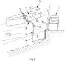
- FIG 6 represents an example of a marine terminal comprising a loading and unloading station 75, a subsea pipeline 76 and a land installation 77.
- the loading and unloading station 75 is a fixed offshore installation comprising a mobile arm 74 and a tower 78 which supports the mobile arm 74.
- the mobile arm 74 carries a bundle of insulated flexible pipes 79 which can be connected to the loading/unloading pipelines 73.
- the orientable mobile arm 74 adapts to all sizes of LNG carriers.
- a connecting pipe, not shown, extends inside the tower 78.
- the loading and unloading station 75 allows the loading and unloading of the LNG carrier 70 from or to the onshore installation 77.
- the latter comprises liquefied gas storage tanks 80 and connecting pipes 81 connected by the subsea pipe 76 to the loading or unloading station 75.
- the subsea pipe 76 allows the transfer of liquefied gas between the loading or unloading station 75 and the shore installation 77 over a long distance, for example 5 km, which makes it possible to keep the LNG carrier 70 at a great distance from the coast during loading and unloading operations.
- pumps on board the ship 70 and/or pumps equipping the onshore installation 77 and/or pumps equipping the loading and unloading station 75 are used.
Landscapes
- Engineering & Computer Science (AREA)
- Mechanical Engineering (AREA)
- General Engineering & Computer Science (AREA)
- Physics & Mathematics (AREA)
- Thermal Sciences (AREA)
- Filling Or Discharging Of Gas Storage Vessels (AREA)
- Loading And Unloading Of Fuel Tanks Or Ships (AREA)
Applications Claiming Priority (2)
| Application Number | Priority Date | Filing Date | Title |
|---|---|---|---|
| FR1903169A FR3094448B1 (fr) | 2019-03-26 | 2019-03-26 | Cuve étanche et thermiquement isolante |
| PCT/EP2020/058436 WO2020193665A1 (fr) | 2019-03-26 | 2020-03-25 | Cuve étanche et thermiquement isolante |
Publications (3)
| Publication Number | Publication Date |
|---|---|
| EP3948060A1 EP3948060A1 (fr) | 2022-02-09 |
| EP3948060C0 EP3948060C0 (fr) | 2024-09-11 |
| EP3948060B1 true EP3948060B1 (fr) | 2024-09-11 |
Family
ID=67185462
Family Applications (1)
| Application Number | Title | Priority Date | Filing Date |
|---|---|---|---|
| EP20713894.2A Active EP3948060B1 (fr) | 2019-03-26 | 2020-03-25 | Cuve étanche et thermiquement isolante |
Country Status (11)
| Country | Link |
|---|---|
| US (1) | US11719388B2 (pl) |
| EP (1) | EP3948060B1 (pl) |
| JP (1) | JP7408679B2 (pl) |
| KR (1) | KR20210141525A (pl) |
| CN (1) | CN113646574B (pl) |
| ES (1) | ES2999540T3 (pl) |
| FR (1) | FR3094448B1 (pl) |
| PH (1) | PH12021552262A1 (pl) |
| PL (1) | PL3948060T3 (pl) |
| SG (1) | SG11202109984QA (pl) |
| WO (1) | WO2020193665A1 (pl) |
Families Citing this family (9)
| Publication number | Priority date | Publication date | Assignee | Title |
|---|---|---|---|---|
| FR3114863B1 (fr) * | 2020-10-02 | 2023-01-13 | Gaztransport Et Technigaz | Procédé d’assemblage et installation de cuve de stockage pour gaz liquéfié |
| FR3129456B1 (fr) * | 2021-11-24 | 2024-05-31 | Gaztransport Et Technigaz | Cuve étanche et thermiquement isolante |
| FR3135125B1 (fr) * | 2022-04-27 | 2024-08-09 | Gaztransport Et Technigaz | Paroi de cuve comportant une conduite traversante |
| FR3140926B1 (fr) * | 2022-10-14 | 2024-09-06 | Gaztransport Et Technigaz | Cuve de stockage de gaz liquide comprenant un puisard |
| FR3143711B1 (fr) * | 2022-12-16 | 2024-11-01 | Gaztransport Et Technigaz | Cuve étanche et thermiquement isolante comportant un élément traversant |
| FR3146189B1 (fr) * | 2023-02-28 | 2025-02-07 | Gaztransport Et Technigaz | Installation de stockage pour gaz liquéfié |
| FR3144643A1 (fr) * | 2023-06-07 | 2024-07-05 | Gaztransport Et Technigaz | Procédé d’assemblage de plaques pour réaliser une membrane étanche |
| FR3157917A1 (fr) | 2024-01-03 | 2025-07-04 | Gaztransport Et Technigaz | Cuve étanche et thermiquement isolante |
| CN120351442A (zh) * | 2025-06-03 | 2025-07-22 | 江南造船(集团)有限责任公司 | 一种液罐集液区域绝热系统及安装方法 |
Family Cites Families (11)
| Publication number | Priority date | Publication date | Assignee | Title |
|---|---|---|---|---|
| FR2691520B1 (fr) | 1992-05-20 | 1994-09-02 | Technigaz Ste Nle | Structure préfabriquée de formation de parois étanches et thermiquement isolantes pour enceinte de confinement d'un fluide à très basse température. |
| FR2832783B1 (fr) * | 2001-11-27 | 2004-01-02 | Alstom | Navire methanier |
| FR2861060B1 (fr) | 2003-10-16 | 2006-01-06 | Gaz Transport & Technigaz | Structure de paroi etanche et cuve munie d'une telle structure |
| KR20100092748A (ko) * | 2009-02-13 | 2010-08-23 | 삼성중공업 주식회사 | Lng 운반선의 lng 저장 탱크 내부 구조 |
| FR2961580B1 (fr) * | 2010-06-17 | 2012-07-13 | Gaztransport Et Technigaz | Cuve etanche et isolante comportant un pied de support |
| FR2991430A1 (fr) * | 2012-05-31 | 2013-12-06 | Gaztransp Et Technigaz | Procede d'etancheification d'une barriere d'etancheite secondaire d'une cuve etanche et thermiquement isolante |
| FR2996520B1 (fr) | 2012-10-09 | 2014-10-24 | Gaztransp Et Technigaz | Cuve etanche et thermiquement isolante comportant une membrane metalique ondulee selon des plis orthogonaux |
| FR3023257B1 (fr) * | 2014-07-04 | 2017-12-29 | Gaztransport Et Technigaz | Cuve etanche et isolante disposee dans une double coque flottante |
| FR3035175B1 (fr) * | 2015-04-20 | 2017-04-28 | Gaztransport Et Technigaz | Cuve etanche et thermiquement isolante equipee d'un element traversant |
| FR3038360B1 (fr) * | 2015-07-03 | 2019-07-26 | Gaztransport Et Technigaz | Dispositif de fixation de canalisation dans un logement |
| FR3049678B1 (fr) * | 2016-04-01 | 2018-04-13 | Gaztransport Et Technigaz | Bloc de bordure thermiquement isolant pour la fabrication d'une paroi de cuve |
-
2019
- 2019-03-26 FR FR1903169A patent/FR3094448B1/fr active Active
-
2020
- 2020-03-25 JP JP2021557194A patent/JP7408679B2/ja active Active
- 2020-03-25 EP EP20713894.2A patent/EP3948060B1/fr active Active
- 2020-03-25 WO PCT/EP2020/058436 patent/WO2020193665A1/fr not_active Ceased
- 2020-03-25 US US17/437,335 patent/US11719388B2/en active Active
- 2020-03-25 SG SG11202109984Q patent/SG11202109984QA/en unknown
- 2020-03-25 KR KR1020217030829A patent/KR20210141525A/ko active Pending
- 2020-03-25 PH PH1/2021/552262A patent/PH12021552262A1/en unknown
- 2020-03-25 PL PL20713894.2T patent/PL3948060T3/pl unknown
- 2020-03-25 CN CN202080024697.XA patent/CN113646574B/zh active Active
- 2020-03-25 ES ES20713894T patent/ES2999540T3/es active Active
Also Published As
| Publication number | Publication date |
|---|---|
| PL3948060T3 (pl) | 2025-02-17 |
| ES2999540T3 (en) | 2025-02-26 |
| WO2020193665A1 (fr) | 2020-10-01 |
| CN113646574A (zh) | 2021-11-12 |
| JP2022526341A (ja) | 2022-05-24 |
| FR3094448B1 (fr) | 2022-06-17 |
| EP3948060C0 (fr) | 2024-09-11 |
| US20220146049A1 (en) | 2022-05-12 |
| CN113646574B (zh) | 2023-09-08 |
| FR3094448A1 (fr) | 2020-10-02 |
| US11719388B2 (en) | 2023-08-08 |
| EP3948060A1 (fr) | 2022-02-09 |
| KR20210141525A (ko) | 2021-11-23 |
| JP7408679B2 (ja) | 2024-01-05 |
| SG11202109984QA (en) | 2021-10-28 |
| PH12021552262A1 (en) | 2022-07-11 |
Similar Documents
| Publication | Publication Date | Title |
|---|---|---|
| EP3948060B1 (fr) | Cuve étanche et thermiquement isolante | |
| EP2956352B1 (fr) | Paroi, etanche et thermiquement isolante, pour cuve de stockage de fluide | |
| EP3320256B1 (fr) | Cuve etanche et thermiquement isolante ayant une membrane d'etancheite secondaire equipee d'un arrangement d'angle a toles metalliques ondulees | |
| EP3365592B1 (fr) | Cuve comprenant des blocs isolants de coin equipes de fentes de relaxation | |
| EP3749889A1 (fr) | Installation pour le stockage et le transport d'un gaz liquefie | |
| WO2019239048A1 (fr) | Cuve etanche et thermiquement isolante | |
| FR3082596A1 (fr) | Cuve etanche et thermiquement isolante a ondulations continues dans le dome liquide | |
| WO2020039134A1 (fr) | Paroi de cuve étanche et thermiquement isolante | |
| EP4269863A1 (fr) | Paroi de cuve comportant une conduite traversante | |
| FR3094071A1 (fr) | Cuve étanche et thermiquement isolante | |
| WO2019239053A1 (fr) | Cuve etanche munie d'un element de jonction ondule | |
| EP3827195A1 (fr) | Cuve etanche et thermiquement isolante | |
| WO2023001678A1 (fr) | Installation de stockage pour gaz liquéfié | |
| FR3115093A1 (fr) | Cuve étanche et thermiquement isolante | |
| WO2023036769A1 (fr) | Installation de stockage pour gaz liquéfié | |
| WO2020016509A1 (fr) | Installation de stockage de fluide | |
| WO2021140218A1 (fr) | Installation de stockage pour gaz liquéfié | |
| WO2021013856A1 (fr) | Membrane d'etancheite pour cuve etanche de stockage de fluide | |
| EP3645933B1 (fr) | Membrane etanche et procede d'assemblage d'une membrane etanche | |
| WO2023025501A1 (fr) | Installation de stockage pour gaz liquéfié | |
| FR3069903B1 (fr) | Cuve etanche et themiquement isolante | |
| FR3077116A1 (fr) | Cuve etanche et thermiquement isolante | |
| FR3077115A1 (fr) | Cuve etanche et thermiquement isolante. | |
| FR3118796A1 (fr) | Installation de stockage pour gaz liquéfié | |
| FR3110669A1 (fr) | Installation de stockage pour gaz liquéfié |
Legal Events
| Date | Code | Title | Description |
|---|---|---|---|
| STAA | Information on the status of an ep patent application or granted ep patent |
Free format text: STATUS: UNKNOWN |
|
| STAA | Information on the status of an ep patent application or granted ep patent |
Free format text: STATUS: THE INTERNATIONAL PUBLICATION HAS BEEN MADE |
|
| PUAI | Public reference made under article 153(3) epc to a published international application that has entered the european phase |
Free format text: ORIGINAL CODE: 0009012 |
|
| STAA | Information on the status of an ep patent application or granted ep patent |
Free format text: STATUS: REQUEST FOR EXAMINATION WAS MADE |
|
| 17P | Request for examination filed |
Effective date: 20210902 |
|
| AK | Designated contracting states |
Kind code of ref document: A1 Designated state(s): AL AT BE BG CH CY CZ DE DK EE ES FI FR GB GR HR HU IE IS IT LI LT LU LV MC MK MT NL NO PL PT RO RS SE SI SK SM TR |
|
| DAV | Request for validation of the european patent (deleted) | ||
| DAX | Request for extension of the european patent (deleted) | ||
| GRAP | Despatch of communication of intention to grant a patent |
Free format text: ORIGINAL CODE: EPIDOSNIGR1 |
|
| STAA | Information on the status of an ep patent application or granted ep patent |
Free format text: STATUS: GRANT OF PATENT IS INTENDED |
|
| INTG | Intention to grant announced |
Effective date: 20240402 |
|
| GRAS | Grant fee paid |
Free format text: ORIGINAL CODE: EPIDOSNIGR3 |
|
| GRAA | (expected) grant |
Free format text: ORIGINAL CODE: 0009210 |
|
| STAA | Information on the status of an ep patent application or granted ep patent |
Free format text: STATUS: THE PATENT HAS BEEN GRANTED |
|
| AK | Designated contracting states |
Kind code of ref document: B1 Designated state(s): AL AT BE BG CH CY CZ DE DK EE ES FI FR GB GR HR HU IE IS IT LI LT LU LV MC MK MT NL NO PL PT RO RS SE SI SK SM TR |
|
| REG | Reference to a national code |
Ref country code: GB Ref legal event code: FG4D Free format text: NOT ENGLISH |
|
| REG | Reference to a national code |
Ref country code: CH Ref legal event code: EP |
|
| REG | Reference to a national code |
Ref country code: DE Ref legal event code: R096 Ref document number: 602020037501 Country of ref document: DE |
|
| REG | Reference to a national code |
Ref country code: IE Ref legal event code: FG4D Free format text: LANGUAGE OF EP DOCUMENT: FRENCH |
|
| U01 | Request for unitary effect filed |
Effective date: 20240916 |
|
| U07 | Unitary effect registered |
Designated state(s): AT BE BG DE DK EE FI FR IT LT LU LV MT NL PT RO SE SI Effective date: 20241011 |
|
| PG25 | Lapsed in a contracting state [announced via postgrant information from national office to epo] |
Ref country code: GR Free format text: LAPSE BECAUSE OF FAILURE TO SUBMIT A TRANSLATION OF THE DESCRIPTION OR TO PAY THE FEE WITHIN THE PRESCRIBED TIME-LIMIT Effective date: 20241212 |
|
| PG25 | Lapsed in a contracting state [announced via postgrant information from national office to epo] |
Ref country code: HR Free format text: LAPSE BECAUSE OF FAILURE TO SUBMIT A TRANSLATION OF THE DESCRIPTION OR TO PAY THE FEE WITHIN THE PRESCRIBED TIME-LIMIT Effective date: 20240911 |
|
| PG25 | Lapsed in a contracting state [announced via postgrant information from national office to epo] |
Ref country code: RS Free format text: LAPSE BECAUSE OF FAILURE TO SUBMIT A TRANSLATION OF THE DESCRIPTION OR TO PAY THE FEE WITHIN THE PRESCRIBED TIME-LIMIT Effective date: 20241211 |
|
| PG25 | Lapsed in a contracting state [announced via postgrant information from national office to epo] |
Ref country code: RS Free format text: LAPSE BECAUSE OF FAILURE TO SUBMIT A TRANSLATION OF THE DESCRIPTION OR TO PAY THE FEE WITHIN THE PRESCRIBED TIME-LIMIT Effective date: 20241211 Ref country code: HR Free format text: LAPSE BECAUSE OF FAILURE TO SUBMIT A TRANSLATION OF THE DESCRIPTION OR TO PAY THE FEE WITHIN THE PRESCRIBED TIME-LIMIT Effective date: 20240911 Ref country code: GR Free format text: LAPSE BECAUSE OF FAILURE TO SUBMIT A TRANSLATION OF THE DESCRIPTION OR TO PAY THE FEE WITHIN THE PRESCRIBED TIME-LIMIT Effective date: 20241212 |
|
| REG | Reference to a national code |
Ref country code: ES Ref legal event code: FG2A Ref document number: 2999540 Country of ref document: ES Kind code of ref document: T3 Effective date: 20250226 |
|
| U20 | Renewal fee for the european patent with unitary effect paid |
Year of fee payment: 6 Effective date: 20250225 |
|
| PG25 | Lapsed in a contracting state [announced via postgrant information from national office to epo] |
Ref country code: IS Free format text: LAPSE BECAUSE OF FAILURE TO SUBMIT A TRANSLATION OF THE DESCRIPTION OR TO PAY THE FEE WITHIN THE PRESCRIBED TIME-LIMIT Effective date: 20250111 |
|
| PG25 | Lapsed in a contracting state [announced via postgrant information from national office to epo] |
Ref country code: SM Free format text: LAPSE BECAUSE OF FAILURE TO SUBMIT A TRANSLATION OF THE DESCRIPTION OR TO PAY THE FEE WITHIN THE PRESCRIBED TIME-LIMIT Effective date: 20240911 |
|
| PG25 | Lapsed in a contracting state [announced via postgrant information from national office to epo] |
Ref country code: CZ Free format text: LAPSE BECAUSE OF FAILURE TO SUBMIT A TRANSLATION OF THE DESCRIPTION OR TO PAY THE FEE WITHIN THE PRESCRIBED TIME-LIMIT Effective date: 20240911 |
|
| PG25 | Lapsed in a contracting state [announced via postgrant information from national office to epo] |
Ref country code: SK Free format text: LAPSE BECAUSE OF FAILURE TO SUBMIT A TRANSLATION OF THE DESCRIPTION OR TO PAY THE FEE WITHIN THE PRESCRIBED TIME-LIMIT Effective date: 20240911 |
|
| PGFP | Annual fee paid to national office [announced via postgrant information from national office to epo] |
Ref country code: ES Payment date: 20250410 Year of fee payment: 6 |
|
| PLBE | No opposition filed within time limit |
Free format text: ORIGINAL CODE: 0009261 |
|
| STAA | Information on the status of an ep patent application or granted ep patent |
Free format text: STATUS: NO OPPOSITION FILED WITHIN TIME LIMIT |
|
| 26N | No opposition filed |
Effective date: 20250612 |
|
| PG25 | Lapsed in a contracting state [announced via postgrant information from national office to epo] |
Ref country code: MC Free format text: LAPSE BECAUSE OF FAILURE TO SUBMIT A TRANSLATION OF THE DESCRIPTION OR TO PAY THE FEE WITHIN THE PRESCRIBED TIME-LIMIT Effective date: 20240911 |
|
| REG | Reference to a national code |
Ref country code: CH Ref legal event code: H13 Free format text: ST27 STATUS EVENT CODE: U-0-0-H10-H13 (AS PROVIDED BY THE NATIONAL OFFICE) Effective date: 20251023 |
|
| GBPC | Gb: european patent ceased through non-payment of renewal fee |
Effective date: 20250325 |
|
| PG25 | Lapsed in a contracting state [announced via postgrant information from national office to epo] |
Ref country code: GB Free format text: LAPSE BECAUSE OF NON-PAYMENT OF DUE FEES Effective date: 20250325 |
|
| PG25 | Lapsed in a contracting state [announced via postgrant information from national office to epo] |
Ref country code: CH Free format text: LAPSE BECAUSE OF NON-PAYMENT OF DUE FEES Effective date: 20250331 |
|
| PG25 | Lapsed in a contracting state [announced via postgrant information from national office to epo] |
Ref country code: IE Free format text: LAPSE BECAUSE OF NON-PAYMENT OF DUE FEES Effective date: 20250325 |
|
| U20 | Renewal fee for the european patent with unitary effect paid |
Year of fee payment: 7 Effective date: 20260226 |
|
| PGFP | Annual fee paid to national office [announced via postgrant information from national office to epo] |
Ref country code: NO Payment date: 20260226 Year of fee payment: 7 |
|
| PGFP | Annual fee paid to national office [announced via postgrant information from national office to epo] |
Ref country code: TR Payment date: 20260313 Year of fee payment: 7 |
|
| PGFP | Annual fee paid to national office [announced via postgrant information from national office to epo] |
Ref country code: PL Payment date: 20260223 Year of fee payment: 7 |