EP3948076B1 - A burner and a method for maintaining a burner lance - Google Patents
A burner and a method for maintaining a burner lance Download PDFInfo
- Publication number
- EP3948076B1 EP3948076B1 EP20713350.5A EP20713350A EP3948076B1 EP 3948076 B1 EP3948076 B1 EP 3948076B1 EP 20713350 A EP20713350 A EP 20713350A EP 3948076 B1 EP3948076 B1 EP 3948076B1
- Authority
- EP
- European Patent Office
- Prior art keywords
- burner
- pipe
- burner lance
- lance
- inner pipe
- Prior art date
- Legal status (The legal status is an assumption and is not a legal conclusion. Google has not performed a legal analysis and makes no representation as to the accuracy of the status listed.)
- Active
Links
Images




Classifications
-
- F—MECHANICAL ENGINEERING; LIGHTING; HEATING; WEAPONS; BLASTING
- F23—COMBUSTION APPARATUS; COMBUSTION PROCESSES
- F23D—BURNERS
- F23D11/00—Burners using a direct spraying action of liquid droplets or vaporised liquid into the combustion space
- F23D11/36—Details
-
- F—MECHANICAL ENGINEERING; LIGHTING; HEATING; WEAPONS; BLASTING
- F23—COMBUSTION APPARATUS; COMBUSTION PROCESSES
- F23C—METHODS OR APPARATUS FOR COMBUSTION USING FLUID FUEL OR SOLID FUEL SUSPENDED IN A CARRIER GAS OR AIR
- F23C5/00—Disposition of burners with respect to the combustion chamber or to one another; Mounting of burners in combustion apparatus
- F23C5/08—Disposition of burners
- F23C5/14—Disposition of burners to obtain a single flame of concentrated or substantially planar form, e.g. pencil or sheet flame
-
- F—MECHANICAL ENGINEERING; LIGHTING; HEATING; WEAPONS; BLASTING
- F23—COMBUSTION APPARATUS; COMBUSTION PROCESSES
- F23D—BURNERS
- F23D11/00—Burners using a direct spraying action of liquid droplets or vaporised liquid into the combustion space
- F23D11/10—Burners using a direct spraying action of liquid droplets or vaporised liquid into the combustion space the spraying being induced by a gaseous medium, e.g. water vapour
- F23D11/106—Burners using a direct spraying action of liquid droplets or vaporised liquid into the combustion space the spraying being induced by a gaseous medium, e.g. water vapour medium and fuel meeting at the burner outlet
-
- F—MECHANICAL ENGINEERING; LIGHTING; HEATING; WEAPONS; BLASTING
- F23—COMBUSTION APPARATUS; COMBUSTION PROCESSES
- F23D—BURNERS
- F23D11/00—Burners using a direct spraying action of liquid droplets or vaporised liquid into the combustion space
- F23D11/10—Burners using a direct spraying action of liquid droplets or vaporised liquid into the combustion space the spraying being induced by a gaseous medium, e.g. water vapour
- F23D11/108—Burners using a direct spraying action of liquid droplets or vaporised liquid into the combustion space the spraying being induced by a gaseous medium, e.g. water vapour medium and fuel intersecting downstream of the burner outlet
-
- F—MECHANICAL ENGINEERING; LIGHTING; HEATING; WEAPONS; BLASTING
- F23—COMBUSTION APPARATUS; COMBUSTION PROCESSES
- F23D—BURNERS
- F23D14/00—Burners for combustion of a gas, e.g. of a gas stored under pressure as a liquid
- F23D14/20—Non-premix gas burners, i.e. in which gaseous fuel is mixed with combustion air on arrival at the combustion zone
- F23D14/22—Non-premix gas burners, i.e. in which gaseous fuel is mixed with combustion air on arrival at the combustion zone with separate air and gas feed ducts, e.g. with ducts running parallel or crossing each other
-
- F—MECHANICAL ENGINEERING; LIGHTING; HEATING; WEAPONS; BLASTING
- F23—COMBUSTION APPARATUS; COMBUSTION PROCESSES
- F23D—BURNERS
- F23D14/00—Burners for combustion of a gas, e.g. of a gas stored under pressure as a liquid
- F23D14/46—Details
-
- F—MECHANICAL ENGINEERING; LIGHTING; HEATING; WEAPONS; BLASTING
- F23—COMBUSTION APPARATUS; COMBUSTION PROCESSES
- F23K—FEEDING FUEL TO COMBUSTION APPARATUS
- F23K5/00—Feeding or distributing other fuel to combustion apparatus
-
- F—MECHANICAL ENGINEERING; LIGHTING; HEATING; WEAPONS; BLASTING
- F23—COMBUSTION APPARATUS; COMBUSTION PROCESSES
- F23C—METHODS OR APPARATUS FOR COMBUSTION USING FLUID FUEL OR SOLID FUEL SUSPENDED IN A CARRIER GAS OR AIR
- F23C2900/00—Special features of, or arrangements for combustion apparatus using fluid fuels or solid fuels suspended in air; Combustion processes therefor
- F23C2900/07021—Details of lances
Definitions
- the invention relates to lances suitable for burners. Such lances are commonly called burner lances.
- the invention relates to burners comprising such lances. Such burners are commonly called lance burners.
- the invention relates to boilers comprising such lance burners and/or burner lances.
- the invention relates to maintenance of burner lances and lance burners.
- Burner lances and lance burners are used to deliver at least two materials into a furnace separately.
- a first material is a carrier medium for delivering some second material
- the second material is a fuel.
- the materials are fluids, i.e. they may be liquid or gaseous.
- the first material may be gaseous, e.g. air or steam
- the second material may be a liquid, e.g. oil or alcohol (e.g. methanol).
- Burner lances typically deliver the first and the second fluid to a nozzle, which mixes the fluids, e.g. by forming a fine spray of the first fluid together with the second fluid.
- a lance is commonly called a gun.
- the document US 2012/0036776 A1 discloses a gasification rector to which an injection device extends.
- the injection devices includes a plurality of substantially concentric conduits coupled to a modular tip.
- the modular tip includes a plurality of cooling channels and a plurality of substantially annular nozzles defined therein.
- Burner lances need to be maintained from time to time. Maintenance may include cleaning the nozzle or changing the nozzle. For maintenance, the burner lance is removed from a furnace or a burner. Burner lances commonly comprise relatively lengthy pipes. Moreover, the furnace, in which the burner lance is used, is typically arranged within a boiler house. For these reasons, a wall of the boiler house needs to be sufficiently far away from the furnace at least at the location, wherein the burner lance is arranged. If not, the relatively lengthy burner lance could not be withdrawn from the furnace, and could therefore not be maintained.
- the lance burner can be maintained even if the free space in between the furnace and the boiler house is small, when the lengthy lance burner is detached to shorter parts.
- a part of the burner lance can be withdraw from the furnace, a part can be detached from the burner lance, and the remaining part of the lance burner can be withdraw from the furnace.
- the shorter part can be detached from the burner lance easily, when the burner lance comprises an openable fastener, i.e. a first openable fastener.
- the first openable fastener can be used for detaching a second part of the burner lance from a first part of the burner lance.
- the openable fastener can be used for fastening the first part of the burner lance to the second part of the burner lance.
- a corresponding burner lance is disclosed in claim 1.
- Figs. 1a , 1b , and 1d show boiler plant 100 comprising boiler 120 provided with a burner 400 comprising a burner lance 200. Since the burner 400 comprises the lance 200 the burner 400 can be called a lance burner 400.
- the burner lance 200 is attached to a nozzle 310 for delivering first fluid and second fluid into a furnace 124 of a boiler 120.
- the boiler 120 in arranged inside a boiler house 110.
- a free space F is arranged in between a wall 122 of a boiler and a wall 112 of the boiler house, and a part of the burner lance 200 is arranged within the free space F.
- the free space F in between the boiler 120 and the boiler house 110 may be small.
- the nozzle 310 may be detachable from the burner lance 200.
- the burner lance 200 For maintenance, the burner lance 200, in particular the nozzle 310 thereof, needs to be withdrawn from the furnace 124.
- the burner lance 200 may be withdrawn from the burner 400 e.g. towards an upper left corner of Figs. 1a , 1b , and 1d .
- an end of the burner lance 200 may hit a wall 112 of the boiler house 110 before the nozzle 310 is withdrawn from the furnace 124.
- a burner lance 200 of an embodiment comprises a first openable fastener 320 for detaching a part of the burner lance 200 from another part of the burner lance 200.
- the boiler 120 may comprise various heat exchangers, including a superheater 132 and an economizer 134.
- the burner lance 200 may be a part of a main burner (e.g. one of main burners) of the boiler. In such a solution fuel(s) is/are only fed to the furnace 124 through the burner lance(s).
- the burner lance may be part of a start burner, and some other fuel, e.g. main fuel, may be also delivered to the furnace 124 and burnt therein.
- the boiler 110 may comprise a combustion air pre-heater 136.
- the boiler 120 may comprise a flue gas cleaner 138, which may comprise at least one of an electrostatic precipitator, a filter, and a scrubber.
- the cleaned flue gas exits through a chimney 140.
- a typical construction is one in which the boiler 120 is suspended from a ceiling of the boiler house 110 by suspension means 142.
- the suspension means 142 may comprise at least one of a beam and a cable.
- the boiler 120 may be e.g. a fluidized bed boiler.
- a cyclone 144 (see Fig. 1d ) is used before the superheater 132 to separate bed material from the flue gas before the cleaned flue gas is conveyed to the superheater 132 and economizer 134.
- the burner lance 200 may be used when running up the fluidized bed combustion. After the bed has been sufficiently heated, the burner lance 200 may be withdrawn from the furnace 124, and the boiler 120 may be operated using only main fuel (e.g. solid fuel), such as biomass derived fuel and/or residue derived fuel, which can be supplied into the furnace via a channel (see the reference "Main fuel”) other than the burner lance 200.
- main fuel e.g. solid fuel
- the burner lance 200 comprises an inner pipe 210, which limits a first channel 212 for conveying some first fluid to a nozzle 310, and via the nozzle 310 into the furnace 124.
- the first fluid may be liquid or gaseous, preferably gaseous.
- the first fluid may comprise oxygen, e.g. the first fluid may comprise or consist of air.
- the first fluid may comprise or consist of steam.
- combustion air may be fed to the furnace also with other means (see Figs. 1a , 1b and 1d ; references 422, 442, and "Air").
- the burner lance 200 comprises an outer pipe 220.
- the outer pipe 220 laterally surrounds the inner pipe 210.
- a second channel 222 for conveying the second fluid to the nozzle 310 is arranged in between the inner pipe 210 and the outer pipe 220.
- the pipes 210, 220 need not be circular in cross section. However, preferably the pipes 210, 220 have a circular cross section, and the pipes 210, 220 extend co-axially. When circular, the outer pipe 220 surrounds the inner pipe 210 radially.
- the second fluid may be liquid or gaseous.
- the second fluid may comprise hydrocarbons, e.g. the second fluid may comprise oil, liquid petroleum gas, and/or some alcohol (e.g. methanol).
- the burner lance may comprise further outer pipes 230, 240 (see Figs. 6b to 6d ). In such a case, the outer pipe 220 may be referred to as a primary outer pipe 220.
- a purpose of the nozzle 310 is to deliver the first fluid and the second fluid into the furnace 124.
- a purpose of the nozzle 310 is to spray at least one of the first fluid and the second fluid into a furnace 124.
- a purpose of the nozzle 310 is to spray at least one of the first fluid and the second fluid into a furnace 124 in the form a small droplets.
- the droplets are formed from the second fluid, while the first fluid acts as the carrier medium (i.e. atomizing medium). It is possible that the small droplets are formed of the first fluid and the second fluid acts as a carrier. These droplets then rapidly evaporate in the furnace 124, thereby enabling easy combustion of the first and/or the second fluid.
- One of the first and second fluids may be a medium that assists the atomizing of the other one of the fluids; typically the first fluid is the medium that assists the atomizing of the second fluid.
- the first and second fluids are gaseous, not further atomizing is needed.
- the burner lance 200 comprises a first inlet 201 for letting in first fluid into the first channel 212, and a second inlet 202 for letting in second fluid into the second channel 222.
- an embodiment of a method for maintaining the burner lance 200 comprises detaching a second part 200b of the burner lance 200 from a first part 200a of the burner lance 200.
- the order of the first and second parts 200a, 200b is defined such that the first part is attached to the nozzle 310 or is attachable to the nozzle 310.
- a primary end 204a of the first part 200a is attached or attachable to the nozzle 310.
- the nozzle 310 is attached or attachable to primary end 204a of the first part 200a.
- the primary end 204a of the first part 200a is opposite to a secondary end 205a of the first part 200a, which secondary end 205a is attached or attachable to the second part 200b (see Fig. 2b ).
- the nozzle 310 may e.g. fit tightly to a primary end 204a of the first part 200a of the burner lance.
- the first part 200a of burner lance 200 fits with the nozzle 310 so tightly that first and second fluids flow only through the nozzle 310.
- the first part 210a of the inner pipe 210 fits with the nozzle 310 so tightly that flow of the first fluid in between the first part 210a of the inner pipe 210 and nozzle 310 is prevented.
- the first part 210a of the inner pipe 210 fits with the nozzle 310 so tightly that the first fluid flows only through the nozzle 310.
- the nozzle 310 may be attached to the inner pipe 210 in a similar manner as the first part 210a of the inner pipe 210 is attached to the second part 210b of the inner pipe 210 (see below). If a groove of the inner pipe 210 fits with a groove of the nozzle, as shown in Figs. 5a to 5c , a part of the nozzle 310 may radially encircle a part of the inner pipe 210 ( Figs. 5a and 5b ), or a part of the inner pipe 210 may radially encircle a part of the nozzle 310 ( Fig. 5c ). As an alternative to fitting the parts together, the nozzle 310 may be welded to the primary end 204a of the first part 200a of the burner lance, e.g. to an end of the inner pipe 210.
- the first part 200a of the burner lance 200 comprises a first part 210a of the inner pipe 210 and a first part 220a of the outer pipe 220; and the first part 200a is attachable to the nozzle 310 or is attached to the nozzle 310.
- a first part comprises the nozzle 310.
- the first part 200a is attachable or attached to the nozzle 310, preferably, the first part 210a of the inner pipe 210 is attachable or attached, respectively, to the nozzle 310.
- the nozzle 310 may be detachable from the first part 200a to further help maintenance. In this way, a seam 312 may be left in between the nozzle 310 and the first part 200a (see Figs. 5a to 5c ).
- the nozzle 310 may be made from different material than the inner pipe 210 or the outer pipe 220.
- the second part 200b of the burner lance 200 comprises a second part 210b of the inner pipe 210 and a second part 220a of the outer pipe 220.
- the inlets 201, 202 may be arranged in the second part 200b, a third part 200c, or another part of the burner lance 200. What will be said about preferable lengths of the parts 200a, 200b of the burner lance 200 applies in connection with the method.
- the invention relates also to a burner 400 comprising an arrangement comprising the nozzle 310 and the burner lance 200 as detailed above and below.
- the nozzle 310 is attached or attachable to the first part 200a of the burner lance 200, in particular to the primary end 204a thereof.
- the second part 200b of the burner lance 200 can be detached in the aforementioned manner. Thereafter there is sufficient space for withdrawing the first part 200a of the burner lance 200 from the furnace 124. After also the first part 200a has been withdrawn from the furnace, the first part 200a (in particular the nozzle 310) can be maintained, e.g. cleaned and/or replaced by a new nozzle.
- the method comprises maintaining at least the first part 200a of the burner lance 200 and/or the nozzle 310. More precisely, the method comprises maintaining at least the first part 200a of the burner lance 200 and/or the nozzle 310 when no part of the burner lance 200 is arranged within the furnace 124. After maintenance, the first part 200a of the burner lance 200 can be put back to place. At a suitable point, the method comprises fastening the second part 200b of the burner lance 200 to the first part 200a of the burner lance 200.
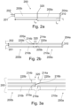
- Fig. 2a shows a burner lance 200 comprising such a first part 200a and a second part 200b, attached to each other with a first openable fastener 320.
- the first part 200a is attachable or attached to the nozzle 310 suitable for delivering at least first and second fluid into the furnace 124.
- the parts 200a, 200b may be sold separately from the nozzle 310.
- the first part 200a is attached to the nozzle 310.
- the first part 200a comprises a first part 210a of the inner pipe 210 and a first part 220a of the outer pipe 220.
- another first part 200a can be defined so that the other first part comprises to the nozzle 310.
- the burner lance it is immaterial whether the burner lance comprises the nozzle or is attached thereto.
- the inner pipe 210 limits a first channel 212 for conveying the first fluid to the nozzle 310.
- the first part 210a of the inner pipe 210 limits a part of the first channel 212.
- the part of the first channel 212 is suitable for conveying the first fluid to the nozzle 310, or, if the first part 200a is not attached to the nozzle 310, the part of the first channel 212 is suitable for conveying the first fluid to the such a part that is attachable to the nozzle 310.
- the first part 220a of the outer pipe 220 laterally surrounds at least a part of the first part 210a of the inner pipe 210.
- a part of the second channel 222 is arranged in between the first part 210a of the inner pipe 210 and the first part 220a of the outer pipe 220. Moreover, the part of the second channel 222 is suitable for conveying the second fluid to the nozzle 310.
- the second part 200b comprises a second part 210b of the inner pipe 210 and a second part 220a of the outer pipe 220.
- the second part 210b of the inner pipe 210 limits a part of the first channel 212.
- the second part 220b of the outer pipe 220 laterally surrounds at least a part of the second part 210b of the inner pipe 210.
- a part of the second channel 222 is arranged in between the second part 210b of the inner pipe 210 and the second part 220b of the outer pipe 220.
- the burner lance 200 comprises the first openable fastener 320.
- the first openable fastener 320 is configured to fasten the first part 200a to the second part 200b in such a way that [A] the first part 210a of the inner pipe 210 fits with the second part 210b of the inner pipe 210 and [B] the first part 220a of the outer pipe 220 fits with the second part 220b of the outer pipe 220.
- the first openable fastener 320 is openable.
- the first openable fastener 320 is configured to be opened in such a way that, once opened, the second part 200b is detachable from the first part 200a.
- the first openable fastener 320 is configured to be opened in such a way that, once first openable fastener 320 is opened, the second part 200b is detachable from the first part 200a without using a tool.
- the burner lance 200 comprises a first inlet 201 for letting in the first fluid into the first channel 212 and a second inlet 202 for letting in the second fluid into the second channel 222.
- the inlets 201, 202 need not be part of the second part 200b.
- the first part 200a of the burner lance 200 does not comprise the inlets 201, 202.
- the first and second fluids are configured to be conveyed through the second part 200b of the burner lance 200 to the first part 200a of the burner lance 200.
- the inner pipe 210 has a profile shape that extends in the direction of length of the burner lance.
- the first 210a and second 210b parts of the inner pipe 210 have a profile shape that extends in the direction of length of the burner lance 200.
- the length l l , of the burner lance 200, which is shown in Fig. 2a in the direction of the length of the lance 200 is at least 1.0 metre, such as from 1.0 m to 5.0 m; e.g. from 1.5 m to 4.0 m.
- the length l l of the burner lance 200 if the burner lance consisted of only one integral part, would be proportional to the size of the free space F in between the boiler 120 and the boiler house 110 needed for maintenance.
- a length l lp2 of the second part 200b in the direction length of the burner lance 200 is from 0.5 m to 2.5 m and a length l lp1 of the first part 200a is from 0.5 m to 2.5 m. Therefore, the requirement of free space is decreased by an amount proportional to the length l lp2 of the the second part 200b.
- a length of the second part 200b is at most 2.0 m or at most 1.5 m and a length of the first part 200a is at most 2.0 m or at most 1.5 m.
- the maximum length affects the requirements for the free space. More preferably, a length l lp2 of the second part 200b is from 0.5 m to 2.0 m or from 0.5 m to 1.5 m and a length l lp1 of the first part 200a is from 0.5 m to 2.5 m or from 0.5 m to 1.5 m.
- the burner lance 200 comprises a third part 200c
- the aforementioned lengths preferably apply also to the third part 200c.
- a diameter of the burner lance 200 depends on the needs.
- an inner diameter of the inner pipe 210 is from 10 mm to 200 mm, more typically from 30 mm to 70 mm.
- an inner diameter of the outer pipe 220 is from 5 mm to 100 mm greater than an outer diameter of the inner pipe 210, more typically from 15 mm to 40 mm greater than an outer diameter of the inner pipe 210.
- the first part 200a is provided with a first primary support 214a, as indicated in Figs. 2b and 3a .
- the first primary support 214a supports the first part 210a of the inner pipe 210 to the first part 220a of the outer pipe 220.
- the first primary support 214a supports an outer surface of the first part 210a of the inner pipe 210 to an inner surface of the first part 220a of the outer pipe 220.
- the first part 200a is provided with at least three first primary supports 214a arranged at the same longitudinal position, and thus laterally surrounding a part of the first part 210a of the inner pipe 210.
- a distance between the end 205a (see Fig. 2b for the ends 205a and 205b) of the first part 200a and a first primary support 214a, as measured in the longitudinal direction of the inner pipe 210, is preferably small, e.g. up to one third of the length of the first part 210a of the inner pipe 210.
- the second part 200b is provided with a second primary support 214b, as indicated in Figs. 2b and 3a .
- the second primary support 214b supports the second part 210b of the inner pipe 210 to the second part 220b of the outer pipe 220.
- the second part 200b is provided with at least three second primary supports 214b arranged at the same longitudinal position, and thus laterally surrounding a part of the second part 210b of the inner pipe 210. Distances between all two neighbouring second primary supports 214b, as measured along the outer surface of the inner pipe 210, may be equal.
- a distance between the end 205b of the second part 200b and a second primary support 214b, as measured in the longitudinal direction of the inner pipe 210, is preferably small, e.g. up to one third of the length of the second part 210b of the inner pipe 210.
- the primary supports 214a, 214b have the effect that the parts 210a, 210b of the inner pipe 210 are aligned with each other when the parts 220a, 220b of the outer pipe 220 are aligned with each other.
- the parts of the outermost pipes e.g. 220a, 220b of the outer pipe 220
- the primary supports 214a, 214b help fastening the first part 200a to the second part 200b in such a way that [A] the first part 210a of the inner pipe 210 fits with the second part 210b of the inner pipe 210 and [B] the first part 220a of the outer pipe 220 fits with the second part 220b of the outer pipe 220.
- the first primary support 214a should resists the flow within the second channel 222 only minimally.
- the first primary support 214a is thin member with e.g. a thickness of at most 5 mm. What has been said about the first primary support 214a preferably applies to the second primary support 214b.
- an end 215a of the first part 210a of the inner pipe 210 is provided with threads, and an end 215b of the second part 210b of the inner pipe 210 is provided with treads.
- the parts 210a, 210b may be turned to detach and attach the parts 210a, 210b to each other.
- the first part 210a of the inner pipe 210 fits with the second part 210b of the inner pipe 210 so tightly that flow of the first fluid and/or the second fluid in between the first part 210a of the inner pipe 210 and the second part 210b of the inner pipe 210 is prevented.
- an end 215a of the first part 210a of the inner pipe 210 is provided with a first groove 216a.
- the first groove 216a is arranged on an outer surface of the first part 210a of an inner pipe 210.
- the first groove 216a is arranged on an inner surface of the first part 210a of an inner pipe 210.
- an end 215b of the second part 210b of the inner pipe 210 is provided with a second groove 216b.
- the second groove 216b is arranged on an inner surface of the second part 210b of the inner pipe 210.
- the second groove 216b is arranged on an outer surface of the second part 210b of the inner pipe 210.
- the first groove of the first part 210a of the inner pipe 210 fits with the second groove of the second part 210b of the inner pipe 210 because of the matching grooves 216a, 216b.
- a length of the first part 210a of the inner pipe 210 is greater than a length of a first part 220a of the outer pipe 220 and/or a length of the second part 220a of the inner pipe 210 is greater than a length of the second part 220b of the outer pipe 220. This has the effect that a seam formed by the first and second grooves (216a and 216b) has a certain length (e.g.
- the first groove 216a fits with the second groove 216b so tightly that flow of the first fluid and/or the second fluid in between the first part 210a of the inner pipe 210 and the second part 210b of the inner pipe 210 is prevented.
- Figure 5a shows the solution of Fig. 4a , wherein the first part 200a is attached to the nozzle 310.
- the seam between the first part 210a of the inner pipe and the second part 210b of the inner pipe 210 may be arranged at a same longitudinal position as the first openable fastener 320; e.g. at a same longitudinal position as the flanges 292a, 292b.
- the first openable fastener 320 e.g. at a same longitudinal position as the flanges 292a, 292b.
- the first part 210a of the inner pipe 210 is longer than the first part 220a of the inner pipe 220 and the second part 210b of the inner pipe 210 is shorter than the second part 220b of the outer pipe 220.
- the seam need not be arranged at a same longitudinal position as the first openable fastener 320.
- the first part 210a of the inner pipe 210 is shorter than the first part 220a of the inner pipe 220 and the second part 210b of the inner pipe 210 is longer than the second part 220b of the outer pipe 220. In such a case, the seam need not be arranged at a same longitudinal position as the first openable fastener 320.
- Figures 3d1 and 3d2 show the end 215a of the first part 210a of the inner pipe 210 in more detail.
- a first tongue 218a is arranged at the same longitudinal position as the first groove 216a.
- the first tongue 218a may be arranged in between the first groove 216a and a central axis of the first part 210a of the inner pipe 210 as in Fig. 3d1 .
- the first groove 216a may be arranged in between the first tongue 218a and a central axis of the first part 210a of the inner pipe 210 as in Fig. 3d2 .
- the first tongue 218a tapers towards the first end 215a, as indicated in Figs. 3d1 and 3d2 .
- the tapering may be a result of a bevel 218a1 (see Fig. 3d1 ) provided at the end 215a of the first part 210a of the inner pipe 210.
- the bevel 218a1 may be provided at an end of the first tongue 218a.
- the tapering of the first tongue 218a may be a result of a rounding 218a2 (see Fig. 3d2 ) provided at the end 215a of the first part 210a of the inner pipe 210.
- the rounding 218a2 may be provided at an end of the first tongue 218a.
- the first part 210a of the inner pipe 210 can be easily fixed to the second part 210b of the inner pipe 210.
- Such a tapering shape is detail for the first part 200a only in Figs. 3d1 and 3d2 .
- the tongue 218b of the second part 210b of the inner pipe 210 may taper towards the second end 215b of the second part 210b in a similar manner as the first part 210a tapers towards the first end 215a (see Fig. 3d3 ).
- a second tongue 218b is arranged at the same longitudinal position as the second groove 216b.
- the second tongue 218b may be arranged in between the second groove 216b and a central axis of the first second 210b of the inner pipe 210 (not shown).
- the second groove 216b may be arranged in between the second tongue 218b and a central axis of the second part 210b of the inner pipe 210 as in Fig. 3d3 .
- the second tongue 218b tapers towards the second end 215b.
- the tapering may be a result of a bevel 218a1 (see Fig. 3d3 ) provided at the end 215b of the second part 210b of the inner pipe 210.
- the bevel 218b1 may be provided at an end of the second tongue 218b.
- the second end 215b of the second part 210a is depicted e.g. in Fig. 3b without the tapering shape.
- an end 205a (see Fig. 2b for the ends 205a and 205b) of the first part 200a, i.e. the secondary end 205a of the first part 200a as discussed above, is provided with a first flange 292a and an end 205b of the second part 200b is provided with a second flange 292b.
- the openable fastener 320 is configured to fasten the first flange 292a to the second flange 292b.
- the first openable fastener 320 comprises a screw 321a or bolt 321b.
- a nut 322 can be provided with a bolt 321b.
- the bolt 321b By screwing the bolt 321b through both the flanges to the nut 322, the flanges 292a, 292b of the parts 200a, 200b can be attached to each other.
- the screw 321a By screwing the screw 321a through one of the flanges (292a, 292b) to the other one of the flanges (292b, 292a), the flanges 292a, 292b of the parts 200a, 200b can be attached to each other.
- a socket 294a may be used as an alternative to the screw 321a or bolt 321b.
- the socket 294a may be used to fasten the first flange 292a to an end of the second part 200b.
- An end of the second part 220b of the outer pipe 220 may be provided with threads 296b that match threads of the socket 294a.
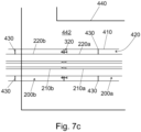
- a socket 294a is used as the first openable fastener 320 inside a protective pipe 410, which may be a part of a burner 400, an outer diameter of the socket 294a should be smaller than an inner diameter of the protective pipe 410 in order to allow air flow within a channel 420 as will be detailed below.
- a lance support 430 other than the socket 294a may be provided.
- the lance support 430 may be provided at a different longitudinal position than the socket 294a. More details of the lance support 430 and protective pipe 410 are given below.
- a gasket 298 (see Fig. 4a ) is arranged in between the first flange 292a and the second flange 292b.
- a purpose of the gasket is to seal the seam in between the parts 220a, 220b of the outer pipe.
- a gasket 298 is arranged in between an end of the first part 220a of the outer pipe 220 and the second part 220b of the outer pipe 220.
- an end of both the parts of the inner and outer pipes may be provided with threads, so that parts of inner and outer pipes can be joined by turning the parts 200a, 200b relative to each other about an axis that is parallel to the length of the burner lance 200.
- the second part 210b of the inner pipe 210 may be rotatable relative to the second part 220b of the outer pipe 220 about an axis that is unidirectional with the length of the second part 200b.
- the first openable fastener 320 may comprise a latch, by which the second part 200b may be detachably attached to the first part 200a.
- the burner lance 200 is detachable to more than two parts.
- a burner lance 200 according to Fig. 6a comprises a third part 200c.
- the third part 200c of the burner lance 200 comprises a third part 210c of the inner pipe 210 and a third part 220c of the outer pipe 220.
- the burner lance 200 of Fig. 6a comprises a second openable fastener 322.
- the second openable fastener 322 is configured to fasten the second part 200b of the burner lance 200 to the third part 200c of the burner lance 200.
- the parts 200b and 200c are configured to be attached in such a way that [A] the second part 210b of the inner pipe 210 fits with the third part 210c of the inner pipe 210 and [B] the second part 220b of the outer pipe 220 fits with the third part 220c of the outer pipe 220.
- the second openable fastener 322 is openable, and once opened, the second part 200b is detached from the third part 200c or detachable from the third part 200c, preferably without a tool. What has been said about the connection between the first and second parts 210a, 210b of the inner pipe 210 applies to the connection between the second and third parts 210b, 210c of the inner pipe 210, mutatis mutandis.
- connection between the first and second parts 220a, 220b of the outer pipe 220 applies to the connection between the second and third parts 220b, 220c of the outer pipe 220, mutatis mutandis.
- first openable fastened 320 applied to the second openable fastener 322 mutatis mutandis. If the second openable fastener 322 is configured to operate with flanges, the corresponding ends of the second and third parts 200b, 200c may be provided with flanges.
- the burner lance 200 may comprise a fourth part, and, optionally, also further parts. Such solution may be feasible, if the burner lance 200 is exceptionally long and/or the free space F is exceptionally small.
- the burner lance 200 may comprise further channels, in addition to the first channel 212 and the second channel 222.
- the burner lance 200 comprises a secondary outer pipe 230.
- the secondary outer pipe 230 laterally surrounds the outer pipe 220, i.e. the primary outer pipe 220.
- a third channel 232 for conveying third fluid to the nozzle 310 is arranged in between the primary outer pipe 220 and the secondary outer pipe 230.
- the first part 200a comprises a first part 230a of the secondary outer pipe 230.
- the first part 230a of the secondary outer pipe 230 laterally surrounds the first part 220a of the primary outer pipe 220.
- a corresponding burner lance 200 comprises a third inlet for letting in third fluid into the third channel 232.
- the burner lance comprises an even number (even herein meaning a number 2 ⁇ N, wherein N is an integer and at least one) of channels, e.g. an even number of co-axial pipes.
- the burner lance 200 comprises a tertiary outer pipe 240.
- the tertiary outer pipe 240 laterally surrounds the secondary outer pipe 230.
- a fourth channel 242 for conveying fourth fluid to the nozzle 310 is arranged in between the secondary outer pipe 230 and the tertiary outer pipe 240.
- the first part 200a of the burner lance 200 comprises a first part 240a of the tertiary outer pipe 240.
- the first part 240a of the tertiary outer pipe 240 laterally surrounds the first part 230a of the secondary outer pipe 230.
- a part of the fourth channel 242 is arranged in between the first part 230a of the secondary outer pipe 230 and the first part 240a of the tertiary outer pipe 240.
- a corresponding burner lance 200 comprises a fourth inlet for letting in fourth fluid into the fourth channel 242.
- such a burner lance 200 can be used in such a way that
- Different channels may be used e.g. for different fuels. Different channels may be used e.g. for only one fuel at different power levels of the boiler. Different channels may be used e.g. for different fuels and at different power levels of the boiler.
- further outer pipes may be provided to the burner lance 200 and its parts (200a, 200b, 200c). Such further outer pipe would laterally surround the tertiary outer pipe 240. This applies to the parts 200a, 200b, 200c of the burner lance 200 as well. Such further parts are not shown in the figures.
- an embodiment comprises [a] at least a first secondary support 224a supporting an outer surface of the first part 220a of the primary outer pipe 220 to an inner surface of the first part 230a of the secondary outer pipe 230 and [b] at least a second secondary support 224b supporting an outer surface of the second part 220b of the primary outer pipe 220 to an inner surface of the second part 230b of the secondary outer pipe 230.
- an embodiment comprises [a] at least a first tertiary support 234a supporting an outer surface of the first part 230a of the secondary outer pipe 230 to an inner surface of the first part 240a of the tertiary outer pipe 240 and [b] at least a second tertiary support 234b supporting an outer surface of the second part 230b of the secondary outer pipe 230 to an inner surface of the second part 240b of the tertiary outer pipe 240.
- Fig. 6d What has been said about the number and placement of the first primary supports 214a applies to first secondary supports 224a and first tertiary supports 234a mutatis mutandis. What has been said about the number and placement of the second primary supports 214b applies to second secondary supports 224b and second tertiary supports 234b mutatis mutandis.
- a part of the burner lance 200 is arranged within a protective pipe 410.
- the protective pipe 410 is a part of a burner 400.
- at least the first part 200a or the second part 200b of the burner lance 200 may be supported to the protective pipe 410.
- at least the first part 200a or the second part 200b of the burner lance 200 may be supported to the protective pipe 410 with a tool 710 during maintenance.
- an embodiment relates to an arrangement comprising the burner lance 200 as disclosed above and a tool 710 suitable for supporting the first part 200a of the burner lance 200 to the protective pipe 410.
- the tool 710 may be used during maintenance. However, the tool 710 may be removed after maintenance.
- a burner 400 (i.e. a lance burner 400) comprises a burner lance 200 as discussed above.
- Figs. 1a , 1b , and 1d show such a burner 400 arranged partly in a boiler 120.
- the type of boiler 110 is irrelevant for details of the burner 400.
- the burner 400 further comprises a protective pipe 410 laterally surrounding the burner lance 200.
- a gas channel 420 is arranged in between an outer surface of the burner lance 200 and an inner surface of the protective pipe 410.
- the outer surface of the burner lance 200 may be an outer surface of the outer pipe 220 (as in Figs. 2a - 4c ), an outer surface of the secondary outer pipe 230 (see Fig.
- the burner 400 comprises an inlet 422 for feeding gas, such as air, into the gas channel 420.
- gas such as air
- gas channel 420 By using such gas, accumulation of solid onto the nozzle 310 may be reduced, whereby a need for maintenance can be made reduced.
- the burner 400 comprises a lance support 430 configured to support the outer surface of the burner lance 200 to the inner surface of the protective pipe 410.
- the burner 400 comprises multiple lance supports 430.
- a function of the lance supports 430 is to support the burner lance 200 to the protective pipe 410.
- a function of the lance supports 430 is to provide the gas channel 420 in between the lance 200 and the pipe 410.
- the burner lance 200 is supported to the protective pipe 410 at least at the detachment point of the two parts 200a, 200b of the burner lance 200.
- the burner lance 200 may be supported in such a way by the first openable fastener 320.
- burner lance 200 may be supported in such a way by the first flange 292a and/or the second flange 292b. Therefore, in an embodiment, the first openable fastener 320 is configured to support the outer surface of the burner lance 200 to the inner surface of the protective pipe 410.
- an end 205a of the first part 200a of the burner lance 200a is provided with the first flange 292a
- an end 205b of the second part 200b of the burner lance 200 is provided with the second flange 292b
- the openable fastener 320 is configured to fasten the first flange 292a to the second flange 292b
- the first flange 292a and/or the second flange 292b is configured to support the outer surface of the burner lance 200 to the inner surface of the protective pipe 410.
- a gasket 298 may be arranged in between an end of the first part 220a of the outer pipe 220 and an end of the second part 220b of the outer pipe 220.
- the gasket 298 may be arranged in between the first flange 292a and the second flange 292b.
- the burner 400 comprises an air box 440.
- the air box 440 surrounds laterally the protective pipe 410.
- an air channel 442 is arranged in between an outer surface of protective pipe 410 and an inner surface of the air box 440.
- the air channel 442 is configured to convey air into the furnace 124 (see Fig. 1d ).
- the air channel 442 may be configured to convey combustion air into the furnace 124.
- the boiler 120 may comprise also another combustion air channel, as indicated in Figs. 1b and 1d by the reference "Air". By feeding air through the air channel 442, accumulation of solid onto the nozzle 310 may be reduced, whereby a need for maintenance can be made reduced.
- an embodiment relates to an arrangement comprising the burner 400 as disclosed above and a tool 710 suitable for supporting the first part 200a of the burner lance 200 to the protective pipe 410 of the burner 400.
- the tool 710 may be used during maintenance. However, the tool 710 may be removed after maintenance.
- the burner lance 200 or the burner 400 may be comprised by a boiler plant 100.
- An embodiment of a boiler plant 100 comprises the boiler 120 and the boiler house 110.
- the boiler house 110 comprises a primary wall 112.
- the boiler 120 comprises a secondary wall 122, which limits the furnace 124.
- the secondary wall 122 forms a wall of the furnace 124.
- the burner lance 200 which may be comprised by the burner 400, extends through the secondary wall 122 of the boiler. The free space F remains in between the secondary wall 122 and the primary wall 112.
- the burner lance 200 extends through the secondary wall 122 at a location, and the free space F remains in between that location and the primary wall 112.
- the detachability of the second part 200b of the burner lance 200 has the effect that the free space F may be relatively small.
- a distance d b of the location wherein the burner lance 200 extends through the secondary wall 122 from the primary wall 112 is at most 3 metres or at most 2 metres. Because of detaching the second part 200b, preferably by using the first openable fastener 320, the burner lance 200 can be maintained also in such a small free space F.
- a service platform 130 is used for maintenance.
- the free space F remains above the service platform 130.
- at least a part of the service platform 130 is arranged in between a wall 112 of the boiler house 110 and a wall 122 of the furnace 124.
- at least a part of the service platform 130 is arranged in between
- At least a part of the burner lance 200 or the burner 400 is arranged above the service platform 130. In this way, the burner lance 200 can be maintained by being supported onto the service platform 130. Preferably, at least a part of the burner lance 200 or the burner 400 is arranged at most 2 metres above the service platform 130. In this way, the burner lance 200 can be maintained by standing on the service platform 130. In an embodiment, the burner lance 200 is arranged at a lower part of a boiler 120.
- the burner lance 200 is arranged within the boiler plant 100 in such a way that the longitudinal direction dir l of the burner lance 200 forms an angle ⁇ with the vertical direction dir v , wherein the angle ⁇ is from 0 to 90 degrees.
- Another technical effect of detaching the second part 200b is related to embodiments, in which the angle ⁇ is from 0 to 80 degrees.
- the burner lance 200 is not arranged substantially horizontally. In such a case, withdrawing the burner lance 200 from its position, e.g. from the protective pipe 410, implies that an end of the burner lance 200 rises as the burner lance 200 is withdrawn.
- the longer the burner lance 200 the harder the handling thereof.
- detaching of the second part 200b is beneficial, since this simplifies handling of the burner lance 200, because an end of the burner lance 200 does not rise too high. This effect is even stronger in embodiment, wherein the angle ⁇ is from 10 to 75 degrees or from 30 to 60 degrees.
- At least a part of the burner lance 200 is arranged within the protective pipe 410. At least the first openable fastener 320 is arranged within the protective pipe 410 before maintenance.
- the burner lance 200 is comprised by a burner 400.
- the burner 400 may be comprised by a boiler plant 100.
- the burner lance 200 when used, is attached to a nozzle 310.
- the burner lance 200 can be maintained as follows:
- An embodiment comprises removing a gasket 298 from the burner lance 200.
- An embodiment comprises supporting the first part 200a of the burner lance 200 to the protective pipe 410 with a tool 710.
- the first part 200a of the burner lance 200 may be supported to the protective pipe 410 with the tool 710 when opening the first openable fastener 320 and detaching the second part 200b of the burner lance 200 from the first part 200a of the burner lance 200.
- the burner lance 200 may be assembled in reverse order, e.g. as follows:
- the second part 200b of the burner lance 200 is fastened to the first part 200a of the burner lance 200 such that
- An embodiment comprises arranging a gasket 298 in between the first part 220a of the outer pipe and a second part 220b of the outer pipe 220.
- An embodiment comprises supporting the first part 200a of the burner lance 200 to the protective pipe 410 with a tool 710.
- the first part 200a of the burner lance 200 may be supported to the protective pipe 410 with the tool 710 when fastening the second part 200b of the burner lance 200 to the first part 200a of the burner lance 200.
- the burner lance consists of the two parts 200a, 200b, the first part 210a of the inner pipe 210 and the second part 210b of the inner pipe 210, in combination, form the inner pipe 210 and the first part 220a of the outer pipe 220 and the second part 220b of the outer pipe 220, in combination, form the outer pipe 220.
- the burner lance may comprise the third part 200c.
- the third part 210c of the inner pipe 210 constitutes the inner pipe 210 and also the third part 220c of the outer pipe 220 constitutes the outer pipe 220.
- the burner lance comprises the secondary outer pipe 230, and optionally also the tertiary outer pipe 240
- the second part 200b of the burner lance 200 is fastened to the first part 200a of the burner lance 200 such that
Landscapes
- Engineering & Computer Science (AREA)
- Chemical & Material Sciences (AREA)
- Combustion & Propulsion (AREA)
- Mechanical Engineering (AREA)
- General Engineering & Computer Science (AREA)
- Combustion Of Fluid Fuel (AREA)
- Gas Burners (AREA)
- Furnace Details (AREA)
Applications Claiming Priority (2)
| Application Number | Priority Date | Filing Date | Title |
|---|---|---|---|
| FI20195230A FI129686B (en) | 2019-03-26 | 2019-03-26 | Burner and method for maintaining the burner tube |
| PCT/FI2020/050164 WO2020193849A1 (en) | 2019-03-26 | 2020-03-17 | A burner and a method for maintaining a burner lance |
Publications (2)
| Publication Number | Publication Date |
|---|---|
| EP3948076A1 EP3948076A1 (en) | 2022-02-09 |
| EP3948076B1 true EP3948076B1 (en) | 2023-05-03 |
Family
ID=69941406
Family Applications (1)
| Application Number | Title | Priority Date | Filing Date |
|---|---|---|---|
| EP20713350.5A Active EP3948076B1 (en) | 2019-03-26 | 2020-03-17 | A burner and a method for maintaining a burner lance |
Country Status (7)
| Country | Link |
|---|---|
| EP (1) | EP3948076B1 (da) |
| DK (1) | DK3948076T3 (da) |
| ES (1) | ES2952576T3 (da) |
| FI (1) | FI129686B (da) |
| PL (1) | PL3948076T3 (da) |
| PT (1) | PT3948076T (da) |
| WO (1) | WO2020193849A1 (da) |
Families Citing this family (1)
| Publication number | Priority date | Publication date | Assignee | Title |
|---|---|---|---|---|
| BR202022016480U2 (pt) | 2022-08-18 | 2024-02-27 | Petróleo Brasileiro S.A. - Petrobras | Lança rígida de queimador de caldeira |
Family Cites Families (4)
| Publication number | Priority date | Publication date | Assignee | Title |
|---|---|---|---|---|
| US5307996A (en) * | 1992-08-05 | 1994-05-03 | Takuma Co., Ltd. | Atomizer for slurry fuel |
| CN2905813Y (zh) * | 2006-03-09 | 2007-05-30 | 上海宝钢工程技术有限公司 | 钢水真空精炼顶吹多功能枪 |
| US8828109B2 (en) * | 2010-08-11 | 2014-09-09 | General Electric Company | Method and apparatus for assembling injection devices |
| GB2531010A (en) * | 2014-10-07 | 2016-04-13 | Linde Ag | Incineration of waste |
-
2019
- 2019-03-26 FI FI20195230A patent/FI129686B/en active IP Right Grant
-
2020
- 2020-03-17 PL PL20713350.5T patent/PL3948076T3/pl unknown
- 2020-03-17 DK DK20713350.5T patent/DK3948076T3/da active
- 2020-03-17 ES ES20713350T patent/ES2952576T3/es active Active
- 2020-03-17 PT PT207133505T patent/PT3948076T/pt unknown
- 2020-03-17 EP EP20713350.5A patent/EP3948076B1/en active Active
- 2020-03-17 WO PCT/FI2020/050164 patent/WO2020193849A1/en not_active Ceased
Also Published As
| Publication number | Publication date |
|---|---|
| PL3948076T3 (pl) | 2023-08-28 |
| FI129686B (en) | 2022-06-30 |
| DK3948076T3 (da) | 2023-08-07 |
| ES2952576T3 (es) | 2023-11-02 |
| EP3948076A1 (en) | 2022-02-09 |
| FI20195230A1 (en) | 2020-09-27 |
| PT3948076T (pt) | 2023-07-26 |
| WO2020193849A1 (en) | 2020-10-01 |
Similar Documents
| Publication | Publication Date | Title |
|---|---|---|
| AU2010221809B2 (en) | Primary oxidant feed to oxy-fired circulating fluidized bed (CFB) | |
| EP3948076B1 (en) | A burner and a method for maintaining a burner lance | |
| CN104769384A (zh) | 用于改装燃烧器前部并将第二燃料注入通用炉中的系统和方法 | |
| CN201145751Y (zh) | 火焰检测器用双重冷却导管 | |
| US8210111B2 (en) | Method and system for lining a coal burner nozzle | |
| US8714094B2 (en) | Fuel fluidizing nozzle assembly | |
| US4951581A (en) | Combined oil gun and coal guide for power plant boilers | |
| AU2011217281B2 (en) | Tubular wall assembly and gasification reactor | |
| US20220228742A1 (en) | Incineration plant for solid material and method for replacing its nozzle insert | |
| CN110121619A (zh) | 燃烧器及具备燃烧器的气化炉以及燃烧器的安装方法 | |
| JP6876087B2 (ja) | プロテクタ及びボイラ装置 | |
| EP2308193B1 (en) | Fuel fluidizing nozzle assembly | |
| EP3739262B1 (en) | Fluidized bed apparatus | |
| CN220355400U (zh) | 一种油燃烧装置及煤粉燃烧装置 | |
| JP2025144092A (ja) | 清掃装置 | |
| KR200410399Y1 (ko) | 열팽창이 고려된 이종의 연료 및 약품 분사 장치 | |
| CN121406374A (zh) | 工艺烧嘴及气化炉 | |
| WO2014058381A1 (en) | Supply device for a combustion chamber |
Legal Events
| Date | Code | Title | Description |
|---|---|---|---|
| STAA | Information on the status of an ep patent application or granted ep patent |
Free format text: STATUS: UNKNOWN |
|
| STAA | Information on the status of an ep patent application or granted ep patent |
Free format text: STATUS: THE INTERNATIONAL PUBLICATION HAS BEEN MADE |
|
| PUAI | Public reference made under article 153(3) epc to a published international application that has entered the european phase |
Free format text: ORIGINAL CODE: 0009012 |
|
| STAA | Information on the status of an ep patent application or granted ep patent |
Free format text: STATUS: REQUEST FOR EXAMINATION WAS MADE |
|
| 17P | Request for examination filed |
Effective date: 20210923 |
|
| AK | Designated contracting states |
Kind code of ref document: A1 Designated state(s): AL AT BE BG CH CY CZ DE DK EE ES FI FR GB GR HR HU IE IS IT LI LT LU LV MC MK MT NL NO PL PT RO RS SE SI SK SM TR |
|
| DAV | Request for validation of the european patent (deleted) | ||
| DAX | Request for extension of the european patent (deleted) | ||
| GRAP | Despatch of communication of intention to grant a patent |
Free format text: ORIGINAL CODE: EPIDOSNIGR1 |
|
| STAA | Information on the status of an ep patent application or granted ep patent |
Free format text: STATUS: GRANT OF PATENT IS INTENDED |
|
| INTG | Intention to grant announced |
Effective date: 20221123 |
|
| GRAS | Grant fee paid |
Free format text: ORIGINAL CODE: EPIDOSNIGR3 |
|
| GRAA | (expected) grant |
Free format text: ORIGINAL CODE: 0009210 |
|
| STAA | Information on the status of an ep patent application or granted ep patent |
Free format text: STATUS: THE PATENT HAS BEEN GRANTED |
|
| AK | Designated contracting states |
Kind code of ref document: B1 Designated state(s): AL AT BE BG CH CY CZ DE DK EE ES FI FR GB GR HR HU IE IS IT LI LT LU LV MC MK MT NL NO PL PT RO RS SE SI SK SM TR |
|
| REG | Reference to a national code |
Ref country code: GB Ref legal event code: FG4D |
|
| REG | Reference to a national code |
Ref country code: DE Ref legal event code: R096 Ref document number: 602020010425 Country of ref document: DE |
|
| REG | Reference to a national code |
Ref country code: AT Ref legal event code: REF Ref document number: 1564878 Country of ref document: AT Kind code of ref document: T Effective date: 20230515 Ref country code: CH Ref legal event code: EP |
|
| REG | Reference to a national code |
Ref country code: IE Ref legal event code: FG4D |
|
| P01 | Opt-out of the competence of the unified patent court (upc) registered |
Effective date: 20230602 |
|
| REG | Reference to a national code |
Ref country code: PT Ref legal event code: SC4A Ref document number: 3948076 Country of ref document: PT Date of ref document: 20230726 Kind code of ref document: T Free format text: AVAILABILITY OF NATIONAL TRANSLATION Effective date: 20230720 |
|
| REG | Reference to a national code |
Ref country code: DK Ref legal event code: T3 Effective date: 20230731 |
|
| REG | Reference to a national code |
Ref country code: NL Ref legal event code: FP |
|
| REG | Reference to a national code |
Ref country code: SE Ref legal event code: TRGR |
|
| REG | Reference to a national code |
Ref country code: LT Ref legal event code: MG9D |
|
| REG | Reference to a national code |
Ref country code: AT Ref legal event code: MK05 Ref document number: 1564878 Country of ref document: AT Kind code of ref document: T Effective date: 20230503 |
|
| PG25 | Lapsed in a contracting state [announced via postgrant information from national office to epo] |
Ref country code: NO Free format text: LAPSE BECAUSE OF FAILURE TO SUBMIT A TRANSLATION OF THE DESCRIPTION OR TO PAY THE FEE WITHIN THE PRESCRIBED TIME-LIMIT Effective date: 20230803 Ref country code: AT Free format text: LAPSE BECAUSE OF FAILURE TO SUBMIT A TRANSLATION OF THE DESCRIPTION OR TO PAY THE FEE WITHIN THE PRESCRIBED TIME-LIMIT Effective date: 20230503 |
|
| REG | Reference to a national code |
Ref country code: ES Ref legal event code: FG2A Ref document number: 2952576 Country of ref document: ES Kind code of ref document: T3 Effective date: 20231102 |
|
| PG25 | Lapsed in a contracting state [announced via postgrant information from national office to epo] |
Ref country code: RS Free format text: LAPSE BECAUSE OF FAILURE TO SUBMIT A TRANSLATION OF THE DESCRIPTION OR TO PAY THE FEE WITHIN THE PRESCRIBED TIME-LIMIT Effective date: 20230503 Ref country code: LV Free format text: LAPSE BECAUSE OF FAILURE TO SUBMIT A TRANSLATION OF THE DESCRIPTION OR TO PAY THE FEE WITHIN THE PRESCRIBED TIME-LIMIT Effective date: 20230503 Ref country code: LT Free format text: LAPSE BECAUSE OF FAILURE TO SUBMIT A TRANSLATION OF THE DESCRIPTION OR TO PAY THE FEE WITHIN THE PRESCRIBED TIME-LIMIT Effective date: 20230503 Ref country code: IS Free format text: LAPSE BECAUSE OF FAILURE TO SUBMIT A TRANSLATION OF THE DESCRIPTION OR TO PAY THE FEE WITHIN THE PRESCRIBED TIME-LIMIT Effective date: 20230903 Ref country code: HR Free format text: LAPSE BECAUSE OF FAILURE TO SUBMIT A TRANSLATION OF THE DESCRIPTION OR TO PAY THE FEE WITHIN THE PRESCRIBED TIME-LIMIT Effective date: 20230503 Ref country code: GR Free format text: LAPSE BECAUSE OF FAILURE TO SUBMIT A TRANSLATION OF THE DESCRIPTION OR TO PAY THE FEE WITHIN THE PRESCRIBED TIME-LIMIT Effective date: 20230804 |
|
| PG25 | Lapsed in a contracting state [announced via postgrant information from national office to epo] |
Ref country code: FI Free format text: LAPSE BECAUSE OF FAILURE TO SUBMIT A TRANSLATION OF THE DESCRIPTION OR TO PAY THE FEE WITHIN THE PRESCRIBED TIME-LIMIT Effective date: 20230503 |
|
| PG25 | Lapsed in a contracting state [announced via postgrant information from national office to epo] |
Ref country code: SK Free format text: LAPSE BECAUSE OF FAILURE TO SUBMIT A TRANSLATION OF THE DESCRIPTION OR TO PAY THE FEE WITHIN THE PRESCRIBED TIME-LIMIT Effective date: 20230503 |
|
| PG25 | Lapsed in a contracting state [announced via postgrant information from national office to epo] |
Ref country code: SM Free format text: LAPSE BECAUSE OF FAILURE TO SUBMIT A TRANSLATION OF THE DESCRIPTION OR TO PAY THE FEE WITHIN THE PRESCRIBED TIME-LIMIT Effective date: 20230503 Ref country code: SK Free format text: LAPSE BECAUSE OF FAILURE TO SUBMIT A TRANSLATION OF THE DESCRIPTION OR TO PAY THE FEE WITHIN THE PRESCRIBED TIME-LIMIT Effective date: 20230503 Ref country code: RO Free format text: LAPSE BECAUSE OF FAILURE TO SUBMIT A TRANSLATION OF THE DESCRIPTION OR TO PAY THE FEE WITHIN THE PRESCRIBED TIME-LIMIT Effective date: 20230503 Ref country code: EE Free format text: LAPSE BECAUSE OF FAILURE TO SUBMIT A TRANSLATION OF THE DESCRIPTION OR TO PAY THE FEE WITHIN THE PRESCRIBED TIME-LIMIT Effective date: 20230503 |
|
| REG | Reference to a national code |
Ref country code: DE Ref legal event code: R097 Ref document number: 602020010425 Country of ref document: DE |
|
| PLBE | No opposition filed within time limit |
Free format text: ORIGINAL CODE: 0009261 |
|
| STAA | Information on the status of an ep patent application or granted ep patent |
Free format text: STATUS: NO OPPOSITION FILED WITHIN TIME LIMIT |
|
| 26N | No opposition filed |
Effective date: 20240206 |
|
| PG25 | Lapsed in a contracting state [announced via postgrant information from national office to epo] |
Ref country code: SI Free format text: LAPSE BECAUSE OF FAILURE TO SUBMIT A TRANSLATION OF THE DESCRIPTION OR TO PAY THE FEE WITHIN THE PRESCRIBED TIME-LIMIT Effective date: 20230503 |
|
| PG25 | Lapsed in a contracting state [announced via postgrant information from national office to epo] |
Ref country code: SI Free format text: LAPSE BECAUSE OF FAILURE TO SUBMIT A TRANSLATION OF THE DESCRIPTION OR TO PAY THE FEE WITHIN THE PRESCRIBED TIME-LIMIT Effective date: 20230503 |
|
| REG | Reference to a national code |
Ref country code: CH Ref legal event code: PL |
|
| PG25 | Lapsed in a contracting state [announced via postgrant information from national office to epo] |
Ref country code: BG Free format text: LAPSE BECAUSE OF FAILURE TO SUBMIT A TRANSLATION OF THE DESCRIPTION OR TO PAY THE FEE WITHIN THE PRESCRIBED TIME-LIMIT Effective date: 20230503 |
|
| PG25 | Lapsed in a contracting state [announced via postgrant information from national office to epo] |
Ref country code: LU Free format text: LAPSE BECAUSE OF NON-PAYMENT OF DUE FEES Effective date: 20240317 |
|
| PG25 | Lapsed in a contracting state [announced via postgrant information from national office to epo] |
Ref country code: MC Free format text: LAPSE BECAUSE OF FAILURE TO SUBMIT A TRANSLATION OF THE DESCRIPTION OR TO PAY THE FEE WITHIN THE PRESCRIBED TIME-LIMIT Effective date: 20230503 |
|
| PG25 | Lapsed in a contracting state [announced via postgrant information from national office to epo] |
Ref country code: MC Free format text: LAPSE BECAUSE OF FAILURE TO SUBMIT A TRANSLATION OF THE DESCRIPTION OR TO PAY THE FEE WITHIN THE PRESCRIBED TIME-LIMIT Effective date: 20230503 Ref country code: LU Free format text: LAPSE BECAUSE OF NON-PAYMENT OF DUE FEES Effective date: 20240317 Ref country code: BG Free format text: LAPSE BECAUSE OF FAILURE TO SUBMIT A TRANSLATION OF THE DESCRIPTION OR TO PAY THE FEE WITHIN THE PRESCRIBED TIME-LIMIT Effective date: 20230503 |
|
| PG25 | Lapsed in a contracting state [announced via postgrant information from national office to epo] |
Ref country code: IE Free format text: LAPSE BECAUSE OF NON-PAYMENT OF DUE FEES Effective date: 20240317 |
|
| PG25 | Lapsed in a contracting state [announced via postgrant information from national office to epo] |
Ref country code: IE Free format text: LAPSE BECAUSE OF NON-PAYMENT OF DUE FEES Effective date: 20240317 Ref country code: CH Free format text: LAPSE BECAUSE OF NON-PAYMENT OF DUE FEES Effective date: 20240331 |
|
| PGFP | Annual fee paid to national office [announced via postgrant information from national office to epo] |
Ref country code: ES Payment date: 20250429 Year of fee payment: 6 |
|
| PG25 | Lapsed in a contracting state [announced via postgrant information from national office to epo] |
Ref country code: CY Free format text: LAPSE BECAUSE OF FAILURE TO SUBMIT A TRANSLATION OF THE DESCRIPTION OR TO PAY THE FEE WITHIN THE PRESCRIBED TIME-LIMIT; INVALID AB INITIO Effective date: 20200317 |
|
| PG25 | Lapsed in a contracting state [announced via postgrant information from national office to epo] |
Ref country code: HU Free format text: LAPSE BECAUSE OF FAILURE TO SUBMIT A TRANSLATION OF THE DESCRIPTION OR TO PAY THE FEE WITHIN THE PRESCRIBED TIME-LIMIT; INVALID AB INITIO Effective date: 20200317 |
|
| PG25 | Lapsed in a contracting state [announced via postgrant information from national office to epo] |
Ref country code: TR Free format text: LAPSE BECAUSE OF FAILURE TO SUBMIT A TRANSLATION OF THE DESCRIPTION OR TO PAY THE FEE WITHIN THE PRESCRIBED TIME-LIMIT Effective date: 20230503 |
|
| PGFP | Annual fee paid to national office [announced via postgrant information from national office to epo] |
Ref country code: SE Payment date: 20260319 Year of fee payment: 7 |
|
| PGFP | Annual fee paid to national office [announced via postgrant information from national office to epo] |
Ref country code: GB Payment date: 20260324 Year of fee payment: 7 |
|
| PGFP | Annual fee paid to national office [announced via postgrant information from national office to epo] |
Ref country code: DE Payment date: 20260319 Year of fee payment: 7 Ref country code: DK Payment date: 20260324 Year of fee payment: 7 |
|
| PGFP | Annual fee paid to national office [announced via postgrant information from national office to epo] |
Ref country code: BE Payment date: 20260319 Year of fee payment: 7 Ref country code: IT Payment date: 20260324 Year of fee payment: 7 |
|
| PGFP | Annual fee paid to national office [announced via postgrant information from national office to epo] |
Ref country code: NL Payment date: 20260319 Year of fee payment: 7 |
|
| PGFP | Annual fee paid to national office [announced via postgrant information from national office to epo] |
Ref country code: FR Payment date: 20260323 Year of fee payment: 7 |
|
| PGFP | Annual fee paid to national office [announced via postgrant information from national office to epo] |
Ref country code: PT Payment date: 20260305 Year of fee payment: 7 Ref country code: CZ Payment date: 20260311 Year of fee payment: 7 |
|
| PGFP | Annual fee paid to national office [announced via postgrant information from national office to epo] |
Ref country code: PL Payment date: 20260226 Year of fee payment: 7 |