EP3948178B1 - Capteur de mesure à effet coriolis et appareil de mesure à effet coriolis - Google Patents
Capteur de mesure à effet coriolis et appareil de mesure à effet coriolis Download PDFInfo
- Publication number
- EP3948178B1 EP3948178B1 EP20705197.0A EP20705197A EP3948178B1 EP 3948178 B1 EP3948178 B1 EP 3948178B1 EP 20705197 A EP20705197 A EP 20705197A EP 3948178 B1 EP3948178 B1 EP 3948178B1
- Authority
- EP
- European Patent Office
- Prior art keywords
- sensor
- magnet
- coriolis
- measuring
- measuring tube
- Prior art date
- Legal status (The legal status is an assumption and is not a legal conclusion. Google has not performed a legal analysis and makes no representation as to the accuracy of the status listed.)
- Active
Links
Images

Classifications
-
- G—PHYSICS
- G01—MEASURING; TESTING
- G01F—MEASURING VOLUME, VOLUME FLOW, MASS FLOW OR LIQUID LEVEL; METERING BY VOLUME
- G01F1/00—Measuring the volume flow or mass flow of fluid or fluent solid material wherein the fluid passes through a meter in a continuous flow
- G01F1/76—Devices for measuring mass flow of a fluid or a fluent solid material
- G01F1/78—Direct mass flowmeters
- G01F1/80—Direct mass flowmeters operating by measuring pressure, force, momentum, or frequency of a fluid flow to which a rotational movement has been imparted
- G01F1/84—Coriolis or gyroscopic mass flowmeters
- G01F1/8409—Coriolis or gyroscopic mass flowmeters constructional details
- G01F1/8422—Coriolis or gyroscopic mass flowmeters constructional details exciters
-
- G—PHYSICS
- G01—MEASURING; TESTING
- G01F—MEASURING VOLUME, VOLUME FLOW, MASS FLOW OR LIQUID LEVEL; METERING BY VOLUME
- G01F1/00—Measuring the volume flow or mass flow of fluid or fluent solid material wherein the fluid passes through a meter in a continuous flow
- G01F1/76—Devices for measuring mass flow of a fluid or a fluent solid material
- G01F1/78—Direct mass flowmeters
- G01F1/80—Direct mass flowmeters operating by measuring pressure, force, momentum, or frequency of a fluid flow to which a rotational movement has been imparted
- G01F1/84—Coriolis or gyroscopic mass flowmeters
- G01F1/8409—Coriolis or gyroscopic mass flowmeters constructional details
- G01F1/8427—Coriolis or gyroscopic mass flowmeters constructional details detectors
Definitions
- the invention relates to a Coriolis measuring sensor of a Coriolis measuring device for detecting a mass flow rate or a density of a medium flowing through at least one measuring tube and a Coriolis measuring device with such a Coriolis measuring sensor.
- Coriolis measuring devices for measuring a mass flow rate or a density of a medium flowing through a measuring tube of the measuring device are prior art.
- a sensor for detecting measuring tube vibrations or an exciter for generating measuring tube vibrations can comprise a planar coil and a U-shaped, magnetic field-generating element which surrounds the planar coil.
- a similar Coriolis meter is also in WO 2005/073676 A1 disclosed.
- a disadvantage of such a magnetic field-generating element is the presence of a magnetic field which has a blurred transition to a spatial area without a magnetic field. This results in lower sensitivity for sensors.
- magnets with a spatially defined magnetic field can also be used, but a simple, robust and precise mounting of the magnets poses a challenge.
- the object is achieved by a Coriolis measuring sensor according to independent claim 1 and by a Coriolis measuring device according to independent claim 15.
- a holder as proposed here can be produced particularly easily and inexpensively by means of milling and allows precise and robust positioning of the magnet groups in the respective openings.
- the openings start from the end face.
- the magnet groups are each held in the respective opening by means of an adhesive, the adhesive being in particular a ceramic adhesive.
- the holder is made of a non-magnetic material such as a stainless steel such as 316L or SS420 or aluminum, copper, titanium or a plastic and in particular has a mass density of less than 8 g/cm ⁇ 3.
- a non-magnetic material such as a stainless steel such as 316L or SS420 or aluminum, copper, titanium or a plastic and in particular has a mass density of less than 8 g/cm ⁇ 3.
- the holder can be attached to a measuring tube or to a fixture.
- the outer incisions are each delimited by an outer wall, wherein the magnet groups are each mounted on an associated outer wall.
- the coil of an exciter is set up to apply a force to the associated magnetic device
- the magnetic device of a sensor is set up to induce an electrical voltage in the coil of the associated coil device
- the senor has two headers, with a first header on an upstream side of the sensor being set up to receive a medium flowing into the sensor from a pipeline and to guide it to the inlet of the at least one measuring tube, a second collector being set up to receive the medium emerging from the outlet of the at least one measuring tube and to guide it into the pipeline.
- the measuring sensor has two process connections, in particular flanges, which are designed to connect the measuring sensor to a pipeline.
- the magnetic device is mechanically connected to the associated measuring tube, and the coil device is fixed in terms of translation and rotation with respect to the inlet or outlet.
- the measuring sensor has two pairs of measuring tubes.
- the measuring sensor comprises a carrier body 20 and two measuring tubes, each having an inlet 11.1 and an outlet 11.2.
- the measuring sensor also includes an exciter 12 for exciting measuring tube vibrations and two sensors 13 for detecting measuring tube vibrations.
- the Coriolis measuring device includes an electronics housing 80 in which an electronic measuring/operating circuit 77 is arranged, which is set up to operate the exciter and the sensors and to provide measured values with regard to a medium flowing through the measuring tubes.
- the exciter and the sensors are connected to the electronic measuring/operating circuit 77 by means of electrical connections 24 .
- the senor can have two collectors 17, with a first collector 17.1 on an upstream side of the sensor being set up to receive a medium flowing into the sensor from a pipeline and to lead it to the inlet of the at least one measuring tube, with a second collector 17.2 is set up to receive the medium emerging from the outlet of the at least one measuring tube and to guide it into the pipeline.
- sensors usually have two process connections 18, in particular flanges 18.1, which are set up to connect the sensor to a pipeline.
- the configuration shown here is an example, so the measuring sensor can also have only one measuring tube or more than two measuring tubes.
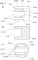
- Fig. 2 a shows a side view of an exemplary holder 15.1 according to the invention of a magnetic device 15, the holder comprising a body 15.3 with three incisions 15.4 which run plane-parallel to one another and perpendicular to an end face 15.311, with a central incision 15.41 passing through an intermediate wall 15.51 of an outer incision in each case 15.42 is separated.
- the face is located at a first end 15.31 of the body.
- the body can be attached to a measuring tube or to a fixture by means of a second end 15.32 opposite the first end.
- an adhesive, welded or screwed connection (not shown) is suitable for this.
- Fig. 2 b sketches a longitudinal section through an intermediate wall 15.51 of the body.
- the intermediate walls 15.51 each have an opening 15.6, which in particular, as shown here, emanates from the end face 15.311.
- Fig. 2 c shows a top view of the end face 15.311 of the body, from which top view the openings 15.6 of the partition walls are visible.
- the incisions and the openings can be cut into the body particularly easily and precisely by milling. This means that rounded edges, which can occur when milling due to a finite milling head diameter, can be avoided and precisely defined edges can be produced.
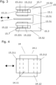
- FIG. 3 shows a side view of a magnet device comprising the in figs 2 a) to c) shown bracket 15.1, in which a first group of magnets 15.21 and a second group of magnets 15.22 is used. Both magnet groups each have a first magnet 15.211/15.221 and a second magnet 15.212/15.222, the magnetic fields of the two magnets of a respective magnet group being oriented in opposite directions. Opposite magnets from different magnet groups have the same magnetic field orientation. In this way, a sharp magnetic field edge is created between the first magnet and the second magnet.
- a magnetic closing device 15.7 in particular a ferromagnetic closing device, is arranged on the rear side of the magnets of a magnet group facing the outer wall 15.52, which is set up to close the field lines of the magnets belonging to the respective magnet group and thus to ensure a higher magnetic flux.
- the magnet group is arranged in the opening of the associated intermediate wall 15.51.
- the geometric dimensions of the magnet group and the opening are preferably matched to one another, so that the magnet group is fixed on three sides by a border around the opening without any significant play.
- the magnet group also acts on the associated outer wall 15.52. In this way, the magnet group can be positioned safely and precisely.
- the magnet groups are each held in the respective opening by means of an adhesive, the adhesive being in particular a ceramic adhesive.
- the body is preferably made of a material that is not magnetic or not very magnetic and, in particular, can be 3D printed, such as stainless steel, aluminum, ceramics, or plastic.
- a magnet device can also have magnet groups with only one magnet each.
- FIG. 4 outlines a relative positioning of a first group of magnets with two magnets 15.21/15.22 with respect to a coil device 14 with a coil 14.1.
- the coil has a central area 14.11 and a winding area surrounding the central area.
- the central area of the coil preferably has an extent in the direction of the relative movements caused by vibrations in the measuring tube which is greater than vibration amplitudes that are typical for the measuring tube and which is smaller than twice a typical vibration amplitude.
- the boundary between the magnets preferably runs perpendicular to the direction of the relative movement.
- the holder 15.3 of a sensor or exciter is preferably arranged on the measuring tube, and the coil device of a sensor or exciter is arranged on the carrier body 20 by means of a holding device.
- the holder of a sensor or exciter is preferably fastened to a first measuring tube and the coil device of a sensor or exciter is fastened to a second measuring tube.
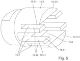
- figure 5 shows a spatial representation of the in figs 2 a) to 2 c) outlined body 15.3 with an end face 15.311 and incisions 15.4, which are separated from one another by the intermediate walls 15.51.
- the partition walls have openings 15.6, in which groups of magnets can be positioned as described.
Landscapes
- Physics & Mathematics (AREA)
- Fluid Mechanics (AREA)
- General Physics & Mathematics (AREA)
- Measuring Volume Flow (AREA)
Claims (15)
- Débitmètre Coriolis (10) d'un appareil de mesure à effet Coriolis (1) destiné à la mesure d'un débit massique ou d'une densité d'un produit s'écoulant à travers au moins un tube de mesure, lequel débitmètre comprend :l'au moins un tube de mesure (11) avec une entrée (11.1) et une sortie (11.2), lequel tube est conçu pour guider le produit entre l'entrée et la sortie ;un corps de support (20), lequel est conçu pour maintenir l'au moins un tube de mesure,au moins un excitateur (12), lequel est conçu pour faire vibrer l'au moins un tube de mesure ;au moins deux capteurs (13), lesquels sont conçus pour mesurer respectivement les vibrations d'au moins un tube de mesure ;au moins un excitateur et/ou au moins un capteur présentant respectivement un dispositif de bobines (14) avec respectivement au moins une bobine (14.1), ainsi que respectivement un dispositif à magnétique (15), le dispositif magnétique et le dispositif de bobines étant mobiles l'un par rapport à l'autre,le dispositif magnétique présentant un support (15.1) et au moins un premier groupe d'aimants (15.21) avec au moins un aimant (15.211, 15.212) et au moins un deuxième groupe d'aimants (15.22) avec au moins un aimant (15.221, 15.222),le support présentant un corps (15.3) avec un axe longitudinal de corps et une première extrémité (15.31) et avec une deuxième extrémité (15.32), la première extrémité présentant une surface frontale (15.311),caractérisé en ce quele corps présente trois entailles (15.4) qui s'étendent dans des plans parallèles entre eux et perpendiculairement à la surface frontale, une entaille centrale (15.41) étant séparée d'une entaille extérieure (15.42) par une paroi intermédiaire (15.51),chaque paroi intermédiaire présentant une ouverture (15.6), les ouvertures étant opposées par rapport à l'entaille centrale,le dispositif de bobines étant disposé au moins par sections dans l'entaille, et le premier groupe d'aimants étant disposé dans une première ouverture, et le deuxième groupe d'aimants étant disposé dans une deuxième ouverture.
- Débitmètre Coriolis selon la revendication 1,
pour lequel les ouvertures partent de la face frontale (15.311). - Débitmètre Coriolis selon la revendication 1 ou 2,
pour lequel les groupes d'aimants sont maintenus chacun dans l'ouverture respective au moyen d'une colle, la colle étant notamment une colle céramique. - Débitmètre Coriolis selon l'une des revendications précédentes,pour lequel chaque groupe d'aimants (15.21, 15.22) comporte deux aimants (15.211, 15.212, 15.221, 15.222) et au moins un dispositif de fermeture (15.7) magnétiquement conducteur, notamment ferromagnétique,les champs magnétiques des deux aimants étant orientés de manière opposée, et le dispositif de fermeture étant conçu pour guider et réunir les lignes de champ des champs magnétiques des deux aimants,les aimants étant en contact mécanique avec le dispositif de fermeture,les champs magnétiques d'aimants opposés de différents groupes d'aimants étant orientés dans le même sens,et le dispositif de fermeture étant disposé sur un côté du groupe d'aimants qui est opposé à l'autre groupe d'aimants.
- Débitmètre Coriolis selon la revendication 4,pour lequel l'au moins une bobine (14.1) présente une zone centrale (14.11) et une zone d'enroulement (14.12) entourant la zone centrale,pour lequel, dans un état de repos de l'au moins un tube de mesure, une limite entre les aimants d'un groupe d'aimants, projetée sur le plan de la section transversale, se trouve au moins par sections dans la zone centrale,et pour lequel les aimants d'un groupe d'aimants sont disposés les uns derrière les autres dans la direction de vibration.
- Débitmètre Coriolis selon l'une des revendications précédentes,
pour lequel le support est réalisé en un matériau non magnétique, par exemple en acier inoxydable ou en aluminium ou en matière plastique, et lequel matériau présente notamment une densité de masse inférieure à 8g/cm3. - Débitmètre Coriolis selon l'une des revendications précédentes,
pour lequel le support peut être fixé à un tube de mesure ou à une fixation. - Débitmètre Coriolis selon l'une des revendications précédentes,pour lequel les entailles extérieures sont délimitées chacune par une paroi extérieure (15.52),pour lequel les groupes d'aimants sont chacun fixés à une paroi extérieure correspondante.
- Débitmètre Coriolis selon l'une des revendications précédentes,pour lequel la bobine d'un excitateur est conçue pour appliquer une force au dispositif magnétique associé, etpour lequel le dispositif magnétique d'un capteur est conçu pour induire une tension électrique dans la bobine du dispositif de bobines associé.
- Débitmètre Coriolis selon l'une des revendications précédentes,le débitmètre comprenant deux collecteurs (17), un premier collecteur (17.1) situé sur un côté amont du débitmètre étant conçu pour recevoir un produit s'écoulant dans le débitmètre à partir d'une conduite et pour le guider vers l'entrée de l'au moins un tube de mesure,un deuxième collecteur (17.2) étant conçu pour recevoir le produit sortant de la sortie de l'au moins un tube de mesure et le guider dans la conduite.
- Débitmètre Coriolis selon l'une des revendications précédentes,
le débitmètre comportant deux raccords process (18), notamment des brides (18.1), lesquels raccords sont adaptés pour relier le débitmètre à une conduite. - Débitmètre Coriolis selon l'une des revendications précédentes,pour lequel le dispositif magnétique est relié mécaniquement au tube de mesure correspondant etpour lequel le dispositif de bobines est fixé en translation et en rotation par rapport à l'entrée et à la sortie.
- Débitmètre Coriolis selon l'une des revendications précédentes,le débitmètre comportant un tube de mesure,le support / le dispositif de bobines du capteur ou de l'excitateur étant respectivement fixé au tube de mesure,et le dispositif de bobines / le support du capteur ou de l'excitateur étant respectivement fixé au corps de support,ou le débitmètre comportant une paire de tubes de mesure, le support / le dispositif de bobines du capteur ou de l'excitateur étant respectivement fixé à un premier tube de mesure, et le dispositif de bobines / le support étant respectivement fixé à un deuxième tube de mesure.
- Débitmètre Coriolis selon la revendication 13,
le débitmètre comportant deux paires de tubes de mesure. - Appareil de mesure à effet Coriolis (1) comprenant :un débitmètre Coriolis (10) selon l'une des revendications précédentes ;un circuit électronique de mesure/d'exploitation (77), le circuit électronique de mesure/d'exploitation étant conçu pour faire fonctionner l'excitateur ainsi que les capteurs,le circuit électronique de mesure/d'exploitation étant en outre conçu pour déterminer et mettre à disposition des valeurs mesurées de débit et/ou des valeurs mesurées de densité,l'appareil de mesure comprenant notamment un boîtier électronique (80) destiné à loger le circuit électronique de mesure et d'exploitation.
Applications Claiming Priority (2)
| Application Number | Priority Date | Filing Date | Title |
|---|---|---|---|
| DE102019107601.3A DE102019107601A1 (de) | 2019-03-25 | 2019-03-25 | Coriolis-Messaufnehmer und Coriolis-Messgerät |
| PCT/EP2020/053907 WO2020193006A1 (fr) | 2019-03-25 | 2020-02-14 | Capteur de mesure à effet coriolis et appareil de mesure à effet coriolis |
Publications (2)
| Publication Number | Publication Date |
|---|---|
| EP3948178A1 EP3948178A1 (fr) | 2022-02-09 |
| EP3948178B1 true EP3948178B1 (fr) | 2023-04-05 |
Family
ID=69582135
Family Applications (1)
| Application Number | Title | Priority Date | Filing Date |
|---|---|---|---|
| EP20705197.0A Active EP3948178B1 (fr) | 2019-03-25 | 2020-02-14 | Capteur de mesure à effet coriolis et appareil de mesure à effet coriolis |
Country Status (5)
| Country | Link |
|---|---|
| US (1) | US11906339B2 (fr) |
| EP (1) | EP3948178B1 (fr) |
| CN (1) | CN113597539B (fr) |
| DE (1) | DE102019107601A1 (fr) |
| WO (1) | WO2020193006A1 (fr) |
Families Citing this family (2)
| Publication number | Priority date | Publication date | Assignee | Title |
|---|---|---|---|---|
| DE102018119332A1 (de) * | 2018-08-08 | 2020-02-13 | Endress+Hauser Flowtec Ag | Messaufnehmer und Messgerät |
| EP4187210B1 (fr) * | 2021-11-24 | 2025-07-09 | Endress+Hauser Flowtec AG | Émetteur de mesure de coriolis et dispositif de mesure de coriolis |
Family Cites Families (19)
| Publication number | Priority date | Publication date | Assignee | Title |
|---|---|---|---|---|
| US4187721A (en) | 1977-07-25 | 1980-02-12 | S & F Associates | Method and structure for flow measurement |
| US4777833A (en) | 1986-11-12 | 1988-10-18 | Micro Motion, Inc. | Ferromagnetic drive and velocity sensors for a coriolis mass flow rate meter |
| CN1022646C (zh) * | 1987-04-20 | 1993-11-03 | 东机工株式会社 | 质量流量计 |
| DE3814702A1 (de) | 1987-11-12 | 1989-05-24 | Bosch Gmbh Robert | Vorrichtung zum betaetigen der drosselklappe einer brennkraftmaschine insbesondere eines kraftfahrzeuges |
| US5115683A (en) * | 1988-09-27 | 1992-05-26 | K-Flow Division Of Kane Steel Co., Inc. | Coriolis mass flow meter adapted for low flow rates |
| CN1058566C (zh) * | 1993-07-21 | 2000-11-15 | 安德雷斯和霍瑟·弗罗泰克有限公司 | 科里奥利式质量流量传感器 |
| US5349872A (en) * | 1993-08-20 | 1994-09-27 | Micro Motion, Inc. | Stationary coils for a coriolis effect mass flowmeter |
| ES2140196T3 (es) * | 1996-04-27 | 2000-02-16 | Flowtec Ag | Captador de caudal masico de coriolis. |
| JPH1151733A (ja) * | 1997-08-04 | 1999-02-26 | Tokico Ltd | 振動式測定装置 |
| EP1253409A1 (fr) * | 2001-04-26 | 2002-10-30 | Endress + Hauser Flowtec AG | Circuit magnétique pour un capteur de mesure |
| US7051598B2 (en) * | 2003-03-21 | 2006-05-30 | Endress + Hauser Flowtec Ag | Magnetic circuit arrangement for a sensor |
| HUP0400330A2 (hu) * | 2004-02-02 | 2005-08-29 | MMG Flow Méréstechnikai Kft. | Áramlási egység Coriolis-típusú tömegárammérőhöz |
| NL1028939C2 (nl) * | 2005-05-02 | 2006-11-03 | Berkin Bv | Massa flowmeter van het Coriolistype. |
| DE102009057912B4 (de) * | 2009-12-11 | 2013-07-25 | Krohne Ag | Coriolis-Massendurchflussmessgerät |
| NL2006895C2 (nl) * | 2011-06-03 | 2012-12-04 | Berkin Bv | Stromingsmeetapparaat en gebruik daarvan voor het bepalen van een stroming van een medium, alsmede werkwijze daarvoor. |
| DE102011114569A1 (de) * | 2011-08-16 | 2013-02-21 | Krohne Ag | Coriolis-Massedurchflussmessgerät |
| JP5922291B1 (ja) * | 2015-10-08 | 2016-05-24 | 株式会社アツデン | コリオリ式質量流量計 |
| DE102015120087B4 (de) * | 2015-11-19 | 2025-12-24 | Endress + Hauser Flowtec Ag | Coriolis-Durchfluss- und/oder Coriolis-Dichtemessgerät mit einem Messaufnehmer vom Vibrationstyp und Verwendung des Coriolis-Durchfluss- und/oder Coriolis-Dichtemessgerätes |
| DE202017006709U1 (de) | 2017-12-07 | 2018-02-12 | Heinrichs Messtechnik Gmbh | Coriolis-Massendurchflussmessgerät |
-
2019
- 2019-03-25 DE DE102019107601.3A patent/DE102019107601A1/de not_active Withdrawn
-
2020
- 2020-02-14 WO PCT/EP2020/053907 patent/WO2020193006A1/fr not_active Ceased
- 2020-02-14 EP EP20705197.0A patent/EP3948178B1/fr active Active
- 2020-02-14 CN CN202080021777.XA patent/CN113597539B/zh active Active
- 2020-02-14 US US17/599,270 patent/US11906339B2/en active Active
Also Published As
| Publication number | Publication date |
|---|---|
| US11906339B2 (en) | 2024-02-20 |
| CN113597539A (zh) | 2021-11-02 |
| US20220316929A1 (en) | 2022-10-06 |
| WO2020193006A1 (fr) | 2020-10-01 |
| DE102019107601A1 (de) | 2020-10-01 |
| CN113597539B (zh) | 2023-12-15 |
| EP3948178A1 (fr) | 2022-02-09 |
Similar Documents
| Publication | Publication Date | Title |
|---|---|---|
| EP4078103B1 (fr) | Unité de support d'un dispositif de mesure pour détecter un débit massique, une viscosité, une densité et/ou une variable dérivée de ceux-ci d'un milieu fluide | |
| EP3529567B1 (fr) | Capteur à ultrasons à clamper destiné à un débitmètre à ultrasons et débitmètre à ultrasons | |
| EP1381831B1 (fr) | Capteur de débit du type vibrant | |
| EP3084367B1 (fr) | Bobine | |
| EP3701231B1 (fr) | Débitmètre massique du type coriolis avec deux paires de tubes de mesure, et procédé de calibration de point zéro d'un tel débitmètre massique | |
| EP3999817B1 (fr) | Capteur de mesure à effet coriolis et appareil de mesure à effet coriolis comprenant un capteur de mesure à effet coriolis | |
| EP3948178B1 (fr) | Capteur de mesure à effet coriolis et appareil de mesure à effet coriolis | |
| EP3762689B1 (fr) | Dispositif de mesure du type coriolis | |
| EP3837504B1 (fr) | Transmetteur d'un dispositif de mesure et dispositif de mesure | |
| EP3788324B1 (fr) | Capteur de mesure à effet coriolis et appareil de mesure à effet coriolis | |
| DE102019134806A1 (de) | Messrohranordnung, Messrohrsystem und Trägereinheit eines Messgerätes zum Erfassen eines Massedurchflusses, einer Viskosität, einer Dichte und/oder einer davon abgeleiteten Größe eines fließfähigen Mediums | |
| EP3935350B1 (fr) | Capteur de coriolis et dispositif de mesure de coriolis avec capteur de coriolis | |
| DE102019123344B3 (de) | Coriolis-Messaufnehmer und Coriolis-Messgerät mit einer Vorrichtung zur Bestimmung eines Alters von Magneten eines Sensors oder Erregers sowie ein Verfahren zur Altersbestimmung | |
| DE102018119941A1 (de) | Messaufnehmer und Messgerät | |
| EP3894803B1 (fr) | Capteur à effet coriolis d'un appareil de mesure à effet coriolis et un appareil de mesure à effet coriolis | |
| DE102018114796A1 (de) | Verfahren zum Betreiben eines Coriolis-Messgeräts sowie ein Coriolis-Messgerät | |
| EP3833942B1 (fr) | Agencement de bobine pour un capteur de vibration ou un excitateur, transmetteur et dispositif de mesure | |
| DE102019107605A1 (de) | Coriolis-Messaufnehmer und Coriolis-Messgerät | |
| WO2021121869A1 (fr) | Capteur de mesure d'un dispositif de mesure | |
| WO2021052707A1 (fr) | Capteur de mesure de coriolis et dispositif de mesure de coriolis | |
| DE102019134600A1 (de) | Messaufnehmer und Coriolis-Messgerät |
Legal Events
| Date | Code | Title | Description |
|---|---|---|---|
| STAA | Information on the status of an ep patent application or granted ep patent |
Free format text: STATUS: UNKNOWN |
|
| STAA | Information on the status of an ep patent application or granted ep patent |
Free format text: STATUS: THE INTERNATIONAL PUBLICATION HAS BEEN MADE |
|
| PUAI | Public reference made under article 153(3) epc to a published international application that has entered the european phase |
Free format text: ORIGINAL CODE: 0009012 |
|
| STAA | Information on the status of an ep patent application or granted ep patent |
Free format text: STATUS: REQUEST FOR EXAMINATION WAS MADE |
|
| 17P | Request for examination filed |
Effective date: 20210816 |
|
| AK | Designated contracting states |
Kind code of ref document: A1 Designated state(s): AL AT BE BG CH CY CZ DE DK EE ES FI FR GB GR HR HU IE IS IT LI LT LU LV MC MK MT NL NO PL PT RO RS SE SI SK SM TR |
|
| DAV | Request for validation of the european patent (deleted) | ||
| DAX | Request for extension of the european patent (deleted) | ||
| GRAP | Despatch of communication of intention to grant a patent |
Free format text: ORIGINAL CODE: EPIDOSNIGR1 |
|
| STAA | Information on the status of an ep patent application or granted ep patent |
Free format text: STATUS: GRANT OF PATENT IS INTENDED |
|
| INTG | Intention to grant announced |
Effective date: 20221024 |
|
| GRAS | Grant fee paid |
Free format text: ORIGINAL CODE: EPIDOSNIGR3 |
|
| GRAA | (expected) grant |
Free format text: ORIGINAL CODE: 0009210 |
|
| STAA | Information on the status of an ep patent application or granted ep patent |
Free format text: STATUS: THE PATENT HAS BEEN GRANTED |
|
| AK | Designated contracting states |
Kind code of ref document: B1 Designated state(s): AL AT BE BG CH CY CZ DE DK EE ES FI FR GB GR HR HU IE IS IT LI LT LU LV MC MK MT NL NO PL PT RO RS SE SI SK SM TR |
|
| REG | Reference to a national code |
Ref country code: GB Ref legal event code: FG4D Free format text: NOT ENGLISH |
|
| REG | Reference to a national code |
Ref country code: CH Ref legal event code: EP |
|
| REG | Reference to a national code |
Ref country code: AT Ref legal event code: REF Ref document number: 1558550 Country of ref document: AT Kind code of ref document: T Effective date: 20230415 |
|
| REG | Reference to a national code |
Ref country code: DE Ref legal event code: R096 Ref document number: 502020002917 Country of ref document: DE |
|
| REG | Reference to a national code |
Ref country code: IE Ref legal event code: FG4D Free format text: LANGUAGE OF EP DOCUMENT: GERMAN |
|
| REG | Reference to a national code |
Ref country code: NL Ref legal event code: FP |
|
| P01 | Opt-out of the competence of the unified patent court (upc) registered |
Effective date: 20230601 |
|
| REG | Reference to a national code |
Ref country code: LT Ref legal event code: MG9D |
|
| PG25 | Lapsed in a contracting state [announced via postgrant information from national office to epo] |
Ref country code: SE Free format text: LAPSE BECAUSE OF FAILURE TO SUBMIT A TRANSLATION OF THE DESCRIPTION OR TO PAY THE FEE WITHIN THE PRESCRIBED TIME-LIMIT Effective date: 20230405 Ref country code: PT Free format text: LAPSE BECAUSE OF FAILURE TO SUBMIT A TRANSLATION OF THE DESCRIPTION OR TO PAY THE FEE WITHIN THE PRESCRIBED TIME-LIMIT Effective date: 20230807 Ref country code: NO Free format text: LAPSE BECAUSE OF FAILURE TO SUBMIT A TRANSLATION OF THE DESCRIPTION OR TO PAY THE FEE WITHIN THE PRESCRIBED TIME-LIMIT Effective date: 20230705 Ref country code: ES Free format text: LAPSE BECAUSE OF FAILURE TO SUBMIT A TRANSLATION OF THE DESCRIPTION OR TO PAY THE FEE WITHIN THE PRESCRIBED TIME-LIMIT Effective date: 20230405 |
|
| PG25 | Lapsed in a contracting state [announced via postgrant information from national office to epo] |
Ref country code: RS Free format text: LAPSE BECAUSE OF FAILURE TO SUBMIT A TRANSLATION OF THE DESCRIPTION OR TO PAY THE FEE WITHIN THE PRESCRIBED TIME-LIMIT Effective date: 20230405 Ref country code: PL Free format text: LAPSE BECAUSE OF FAILURE TO SUBMIT A TRANSLATION OF THE DESCRIPTION OR TO PAY THE FEE WITHIN THE PRESCRIBED TIME-LIMIT Effective date: 20230405 Ref country code: LV Free format text: LAPSE BECAUSE OF FAILURE TO SUBMIT A TRANSLATION OF THE DESCRIPTION OR TO PAY THE FEE WITHIN THE PRESCRIBED TIME-LIMIT Effective date: 20230405 Ref country code: LT Free format text: LAPSE BECAUSE OF FAILURE TO SUBMIT A TRANSLATION OF THE DESCRIPTION OR TO PAY THE FEE WITHIN THE PRESCRIBED TIME-LIMIT Effective date: 20230405 Ref country code: IS Free format text: LAPSE BECAUSE OF FAILURE TO SUBMIT A TRANSLATION OF THE DESCRIPTION OR TO PAY THE FEE WITHIN THE PRESCRIBED TIME-LIMIT Effective date: 20230805 Ref country code: HR Free format text: LAPSE BECAUSE OF FAILURE TO SUBMIT A TRANSLATION OF THE DESCRIPTION OR TO PAY THE FEE WITHIN THE PRESCRIBED TIME-LIMIT Effective date: 20230405 Ref country code: GR Free format text: LAPSE BECAUSE OF FAILURE TO SUBMIT A TRANSLATION OF THE DESCRIPTION OR TO PAY THE FEE WITHIN THE PRESCRIBED TIME-LIMIT Effective date: 20230706 |
|
| PG25 | Lapsed in a contracting state [announced via postgrant information from national office to epo] |
Ref country code: FI Free format text: LAPSE BECAUSE OF FAILURE TO SUBMIT A TRANSLATION OF THE DESCRIPTION OR TO PAY THE FEE WITHIN THE PRESCRIBED TIME-LIMIT Effective date: 20230405 |
|
| REG | Reference to a national code |
Ref country code: DE Ref legal event code: R097 Ref document number: 502020002917 Country of ref document: DE |
|
| PG25 | Lapsed in a contracting state [announced via postgrant information from national office to epo] |
Ref country code: SK Free format text: LAPSE BECAUSE OF FAILURE TO SUBMIT A TRANSLATION OF THE DESCRIPTION OR TO PAY THE FEE WITHIN THE PRESCRIBED TIME-LIMIT Effective date: 20230405 |
|
| PG25 | Lapsed in a contracting state [announced via postgrant information from national office to epo] |
Ref country code: SM Free format text: LAPSE BECAUSE OF FAILURE TO SUBMIT A TRANSLATION OF THE DESCRIPTION OR TO PAY THE FEE WITHIN THE PRESCRIBED TIME-LIMIT Effective date: 20230405 Ref country code: SK Free format text: LAPSE BECAUSE OF FAILURE TO SUBMIT A TRANSLATION OF THE DESCRIPTION OR TO PAY THE FEE WITHIN THE PRESCRIBED TIME-LIMIT Effective date: 20230405 Ref country code: RO Free format text: LAPSE BECAUSE OF FAILURE TO SUBMIT A TRANSLATION OF THE DESCRIPTION OR TO PAY THE FEE WITHIN THE PRESCRIBED TIME-LIMIT Effective date: 20230405 Ref country code: EE Free format text: LAPSE BECAUSE OF FAILURE TO SUBMIT A TRANSLATION OF THE DESCRIPTION OR TO PAY THE FEE WITHIN THE PRESCRIBED TIME-LIMIT Effective date: 20230405 Ref country code: DK Free format text: LAPSE BECAUSE OF FAILURE TO SUBMIT A TRANSLATION OF THE DESCRIPTION OR TO PAY THE FEE WITHIN THE PRESCRIBED TIME-LIMIT Effective date: 20230405 Ref country code: CZ Free format text: LAPSE BECAUSE OF FAILURE TO SUBMIT A TRANSLATION OF THE DESCRIPTION OR TO PAY THE FEE WITHIN THE PRESCRIBED TIME-LIMIT Effective date: 20230405 |
|
| PLBE | No opposition filed within time limit |
Free format text: ORIGINAL CODE: 0009261 |
|
| STAA | Information on the status of an ep patent application or granted ep patent |
Free format text: STATUS: NO OPPOSITION FILED WITHIN TIME LIMIT |
|
| 26N | No opposition filed |
Effective date: 20240108 |
|
| PG25 | Lapsed in a contracting state [announced via postgrant information from national office to epo] |
Ref country code: SI Free format text: LAPSE BECAUSE OF FAILURE TO SUBMIT A TRANSLATION OF THE DESCRIPTION OR TO PAY THE FEE WITHIN THE PRESCRIBED TIME-LIMIT Effective date: 20230405 |
|
| PG25 | Lapsed in a contracting state [announced via postgrant information from national office to epo] |
Ref country code: SI Free format text: LAPSE BECAUSE OF FAILURE TO SUBMIT A TRANSLATION OF THE DESCRIPTION OR TO PAY THE FEE WITHIN THE PRESCRIBED TIME-LIMIT Effective date: 20230405 Ref country code: IT Free format text: LAPSE BECAUSE OF FAILURE TO SUBMIT A TRANSLATION OF THE DESCRIPTION OR TO PAY THE FEE WITHIN THE PRESCRIBED TIME-LIMIT Effective date: 20230405 |
|
| PG25 | Lapsed in a contracting state [announced via postgrant information from national office to epo] |
Ref country code: MC Free format text: LAPSE BECAUSE OF FAILURE TO SUBMIT A TRANSLATION OF THE DESCRIPTION OR TO PAY THE FEE WITHIN THE PRESCRIBED TIME-LIMIT Effective date: 20230405 |
|
| PG25 | Lapsed in a contracting state [announced via postgrant information from national office to epo] |
Ref country code: LU Free format text: LAPSE BECAUSE OF NON-PAYMENT OF DUE FEES Effective date: 20240214 |
|
| PG25 | Lapsed in a contracting state [announced via postgrant information from national office to epo] |
Ref country code: LU Free format text: LAPSE BECAUSE OF NON-PAYMENT OF DUE FEES Effective date: 20240214 |
|
| PG25 | Lapsed in a contracting state [announced via postgrant information from national office to epo] |
Ref country code: BG Free format text: LAPSE BECAUSE OF FAILURE TO SUBMIT A TRANSLATION OF THE DESCRIPTION OR TO PAY THE FEE WITHIN THE PRESCRIBED TIME-LIMIT Effective date: 20230405 |
|
| PG25 | Lapsed in a contracting state [announced via postgrant information from national office to epo] |
Ref country code: BG Free format text: LAPSE BECAUSE OF FAILURE TO SUBMIT A TRANSLATION OF THE DESCRIPTION OR TO PAY THE FEE WITHIN THE PRESCRIBED TIME-LIMIT Effective date: 20230405 |
|
| REG | Reference to a national code |
Ref country code: BE Ref legal event code: MM Effective date: 20240229 |
|
| PG25 | Lapsed in a contracting state [announced via postgrant information from national office to epo] |
Ref country code: BE Free format text: LAPSE BECAUSE OF NON-PAYMENT OF DUE FEES Effective date: 20240229 |
|
| PG25 | Lapsed in a contracting state [announced via postgrant information from national office to epo] |
Ref country code: IE Free format text: LAPSE BECAUSE OF NON-PAYMENT OF DUE FEES Effective date: 20240214 |
|
| PG25 | Lapsed in a contracting state [announced via postgrant information from national office to epo] |
Ref country code: IE Free format text: LAPSE BECAUSE OF NON-PAYMENT OF DUE FEES Effective date: 20240214 Ref country code: BE Free format text: LAPSE BECAUSE OF NON-PAYMENT OF DUE FEES Effective date: 20240229 |
|
| PGFP | Annual fee paid to national office [announced via postgrant information from national office to epo] |
Ref country code: AT Payment date: 20250417 Year of fee payment: 5 Ref country code: CH Payment date: 20250301 Year of fee payment: 6 |
|
| PG25 | Lapsed in a contracting state [announced via postgrant information from national office to epo] |
Ref country code: CY Free format text: LAPSE BECAUSE OF FAILURE TO SUBMIT A TRANSLATION OF THE DESCRIPTION OR TO PAY THE FEE WITHIN THE PRESCRIBED TIME-LIMIT; INVALID AB INITIO Effective date: 20200214 |
|
| PG25 | Lapsed in a contracting state [announced via postgrant information from national office to epo] |
Ref country code: HU Free format text: LAPSE BECAUSE OF FAILURE TO SUBMIT A TRANSLATION OF THE DESCRIPTION OR TO PAY THE FEE WITHIN THE PRESCRIBED TIME-LIMIT; INVALID AB INITIO Effective date: 20200214 |
|
| PG25 | Lapsed in a contracting state [announced via postgrant information from national office to epo] |
Ref country code: TR Free format text: LAPSE BECAUSE OF FAILURE TO SUBMIT A TRANSLATION OF THE DESCRIPTION OR TO PAY THE FEE WITHIN THE PRESCRIBED TIME-LIMIT Effective date: 20230405 |
|
| PGFP | Annual fee paid to national office [announced via postgrant information from national office to epo] |
Ref country code: NL Payment date: 20260218 Year of fee payment: 7 |
|
| PGFP | Annual fee paid to national office [announced via postgrant information from national office to epo] |
Ref country code: GB Payment date: 20260220 Year of fee payment: 7 |
|
| PGFP | Annual fee paid to national office [announced via postgrant information from national office to epo] |
Ref country code: DE Payment date: 20260218 Year of fee payment: 7 |
|
| PG25 | Lapsed in a contracting state [announced via postgrant information from national office to epo] |
Ref country code: AT Free format text: LAPSE BECAUSE OF NON-PAYMENT OF DUE FEES Effective date: 20250214 |
|
| REG | Reference to a national code |
Ref country code: AT Ref legal event code: MM01 Ref document number: 1558550 Country of ref document: AT Kind code of ref document: T Effective date: 20250214 |
|
| PGFP | Annual fee paid to national office [announced via postgrant information from national office to epo] |
Ref country code: FR Payment date: 20260219 Year of fee payment: 7 |