EP3948227B1 - Verfahren und system zur analyse einer probe unter verwendung von cavity-ring-down-spektroskopie - Google Patents
Verfahren und system zur analyse einer probe unter verwendung von cavity-ring-down-spektroskopie Download PDFInfo
- Publication number
- EP3948227B1 EP3948227B1 EP20782958.1A EP20782958A EP3948227B1 EP 3948227 B1 EP3948227 B1 EP 3948227B1 EP 20782958 A EP20782958 A EP 20782958A EP 3948227 B1 EP3948227 B1 EP 3948227B1
- Authority
- EP
- European Patent Office
- Prior art keywords
- sample
- ring
- light intensity
- cavity
- down cavity
- Prior art date
- Legal status (The legal status is an assumption and is not a legal conclusion. Google has not performed a legal analysis and makes no representation as to the accuracy of the status listed.)
- Active
Links
Images




Classifications
-
- G—PHYSICS
- G01—MEASURING; TESTING
- G01N—INVESTIGATING OR ANALYSING MATERIALS BY DETERMINING THEIR CHEMICAL OR PHYSICAL PROPERTIES
- G01N21/00—Investigating or analysing materials by the use of optical means, i.e. using sub-millimetre waves, infrared, visible or ultraviolet light
- G01N21/17—Systems in which incident light is modified in accordance with the properties of the material investigated
- G01N21/25—Colour; Spectral properties, i.e. comparison of effect of material on the light at two or more different wavelengths or wavelength bands
- G01N21/31—Investigating relative effect of material at wavelengths characteristic of specific elements or molecules, e.g. atomic absorption spectrometry
- G01N21/39—Investigating relative effect of material at wavelengths characteristic of specific elements or molecules, e.g. atomic absorption spectrometry using tunable lasers
-
- G—PHYSICS
- G01—MEASURING; TESTING
- G01J—MEASUREMENT OF INTENSITY, VELOCITY, SPECTRAL CONTENT, POLARISATION, PHASE OR PULSE CHARACTERISTICS OF INFRARED, VISIBLE OR ULTRAVIOLET LIGHT; COLORIMETRY; RADIATION PYROMETRY
- G01J3/00—Spectrometry; Spectrophotometry; Monochromators; Measuring colours
- G01J3/02—Details
- G01J3/0205—Optical elements not provided otherwise, e.g. optical manifolds, diffusers, windows
-
- G—PHYSICS
- G01—MEASURING; TESTING
- G01J—MEASUREMENT OF INTENSITY, VELOCITY, SPECTRAL CONTENT, POLARISATION, PHASE OR PULSE CHARACTERISTICS OF INFRARED, VISIBLE OR ULTRAVIOLET LIGHT; COLORIMETRY; RADIATION PYROMETRY
- G01J3/00—Spectrometry; Spectrophotometry; Monochromators; Measuring colours
- G01J3/02—Details
- G01J3/10—Arrangements of light sources specially adapted for spectrometry or colorimetry
-
- G—PHYSICS
- G01—MEASURING; TESTING
- G01J—MEASUREMENT OF INTENSITY, VELOCITY, SPECTRAL CONTENT, POLARISATION, PHASE OR PULSE CHARACTERISTICS OF INFRARED, VISIBLE OR ULTRAVIOLET LIGHT; COLORIMETRY; RADIATION PYROMETRY
- G01J3/00—Spectrometry; Spectrophotometry; Monochromators; Measuring colours
- G01J3/28—Investigating the spectrum
- G01J3/42—Absorption spectrometry; Double beam spectrometry; Flicker spectrometry; Reflection spectrometry
-
- G—PHYSICS
- G01—MEASURING; TESTING
- G01N—INVESTIGATING OR ANALYSING MATERIALS BY DETERMINING THEIR CHEMICAL OR PHYSICAL PROPERTIES
- G01N1/00—Sampling; Preparing specimens for investigation
- G01N1/28—Preparing specimens for investigation including physical details of (bio-)chemical methods covered elsewhere, e.g. G01N33/50, C12Q
- G01N1/40—Concentrating samples
-
- G—PHYSICS
- G01—MEASURING; TESTING
- G01N—INVESTIGATING OR ANALYSING MATERIALS BY DETERMINING THEIR CHEMICAL OR PHYSICAL PROPERTIES
- G01N21/00—Investigating or analysing materials by the use of optical means, i.e. using sub-millimetre waves, infrared, visible or ultraviolet light
- G01N21/17—Systems in which incident light is modified in accordance with the properties of the material investigated
- G01N21/25—Colour; Spectral properties, i.e. comparison of effect of material on the light at two or more different wavelengths or wavelength bands
- G01N21/31—Investigating relative effect of material at wavelengths characteristic of specific elements or molecules, e.g. atomic absorption spectrometry
-
- G—PHYSICS
- G01—MEASURING; TESTING
- G01N—INVESTIGATING OR ANALYSING MATERIALS BY DETERMINING THEIR CHEMICAL OR PHYSICAL PROPERTIES
- G01N21/00—Investigating or analysing materials by the use of optical means, i.e. using sub-millimetre waves, infrared, visible or ultraviolet light
- G01N21/17—Systems in which incident light is modified in accordance with the properties of the material investigated
- G01N21/25—Colour; Spectral properties, i.e. comparison of effect of material on the light at two or more different wavelengths or wavelength bands
- G01N21/31—Investigating relative effect of material at wavelengths characteristic of specific elements or molecules, e.g. atomic absorption spectrometry
- G01N21/35—Investigating relative effect of material at wavelengths characteristic of specific elements or molecules, e.g. atomic absorption spectrometry using infrared light
- G01N21/3504—Investigating relative effect of material at wavelengths characteristic of specific elements or molecules, e.g. atomic absorption spectrometry using infrared light for analysing gases, e.g. multi-gas analysis
-
- G—PHYSICS
- G01—MEASURING; TESTING
- G01N—INVESTIGATING OR ANALYSING MATERIALS BY DETERMINING THEIR CHEMICAL OR PHYSICAL PROPERTIES
- G01N21/00—Investigating or analysing materials by the use of optical means, i.e. using sub-millimetre waves, infrared, visible or ultraviolet light
- G01N21/17—Systems in which incident light is modified in accordance with the properties of the material investigated
- G01N21/55—Specular reflectivity
- G01N21/552—Attenuated total reflection
-
- G—PHYSICS
- G01—MEASURING; TESTING
- G01N—INVESTIGATING OR ANALYSING MATERIALS BY DETERMINING THEIR CHEMICAL OR PHYSICAL PROPERTIES
- G01N33/00—Investigating or analysing materials by specific methods not covered by groups G01N1/00 - G01N31/00
- G01N33/48—Biological material, e.g. blood, urine; Haemocytometers
- G01N33/483—Physical analysis of biological material
- G01N33/497—Physical analysis of biological material of gaseous biological material, e.g. breath
-
- G—PHYSICS
- G01—MEASURING; TESTING
- G01J—MEASUREMENT OF INTENSITY, VELOCITY, SPECTRAL CONTENT, POLARISATION, PHASE OR PULSE CHARACTERISTICS OF INFRARED, VISIBLE OR ULTRAVIOLET LIGHT; COLORIMETRY; RADIATION PYROMETRY
- G01J3/00—Spectrometry; Spectrophotometry; Monochromators; Measuring colours
- G01J3/28—Investigating the spectrum
- G01J3/42—Absorption spectrometry; Double beam spectrometry; Flicker spectrometry; Reflection spectrometry
- G01J2003/423—Spectral arrangements using lasers, e.g. tunable
-
- G—PHYSICS
- G01—MEASURING; TESTING
- G01N—INVESTIGATING OR ANALYSING MATERIALS BY DETERMINING THEIR CHEMICAL OR PHYSICAL PROPERTIES
- G01N1/00—Sampling; Preparing specimens for investigation
- G01N1/02—Devices for withdrawing samples
- G01N1/22—Devices for withdrawing samples in the gaseous state
- G01N1/2202—Devices for withdrawing samples in the gaseous state involving separation of sample components during sampling
- G01N1/2214—Devices for withdrawing samples in the gaseous state involving separation of sample components during sampling by sorption
-
- G—PHYSICS
- G01—MEASURING; TESTING
- G01N—INVESTIGATING OR ANALYSING MATERIALS BY DETERMINING THEIR CHEMICAL OR PHYSICAL PROPERTIES
- G01N21/00—Investigating or analysing materials by the use of optical means, i.e. using sub-millimetre waves, infrared, visible or ultraviolet light
- G01N21/17—Systems in which incident light is modified in accordance with the properties of the material investigated
- G01N21/25—Colour; Spectral properties, i.e. comparison of effect of material on the light at two or more different wavelengths or wavelength bands
- G01N21/31—Investigating relative effect of material at wavelengths characteristic of specific elements or molecules, e.g. atomic absorption spectrometry
- G01N21/39—Investigating relative effect of material at wavelengths characteristic of specific elements or molecules, e.g. atomic absorption spectrometry using tunable lasers
- G01N2021/391—Intracavity sample
-
- G—PHYSICS
- G01—MEASURING; TESTING
- G01N—INVESTIGATING OR ANALYSING MATERIALS BY DETERMINING THEIR CHEMICAL OR PHYSICAL PROPERTIES
- G01N21/00—Investigating or analysing materials by the use of optical means, i.e. using sub-millimetre waves, infrared, visible or ultraviolet light
- G01N21/17—Systems in which incident light is modified in accordance with the properties of the material investigated
- G01N21/25—Colour; Spectral properties, i.e. comparison of effect of material on the light at two or more different wavelengths or wavelength bands
- G01N21/31—Investigating relative effect of material at wavelengths characteristic of specific elements or molecules, e.g. atomic absorption spectrometry
- G01N21/39—Investigating relative effect of material at wavelengths characteristic of specific elements or molecules, e.g. atomic absorption spectrometry using tunable lasers
- G01N2021/396—Type of laser source
- G01N2021/398—CO2 laser
-
- G—PHYSICS
- G01—MEASURING; TESTING
- G01N—INVESTIGATING OR ANALYSING MATERIALS BY DETERMINING THEIR CHEMICAL OR PHYSICAL PROPERTIES
- G01N21/00—Investigating or analysing materials by the use of optical means, i.e. using sub-millimetre waves, infrared, visible or ultraviolet light
- G01N21/75—Systems in which material is subjected to a chemical reaction, the progress or the result of the reaction being investigated
- G01N21/77—Systems in which material is subjected to a chemical reaction, the progress or the result of the reaction being investigated by observing the effect on a chemical indicator
- G01N2021/7769—Measurement method of reaction-produced change in sensor
- G01N2021/7789—Cavity or resonator
-
- G—PHYSICS
- G01—MEASURING; TESTING
- G01N—INVESTIGATING OR ANALYSING MATERIALS BY DETERMINING THEIR CHEMICAL OR PHYSICAL PROPERTIES
- G01N2201/00—Features of devices classified in G01N21/00
- G01N2201/02—Mechanical
- G01N2201/023—Controlling conditions in casing
- G01N2201/0233—Gas purge
- G01N2201/0235—Gas purge with gas filters in casing
-
- G—PHYSICS
- G01—MEASURING; TESTING
- G01N—INVESTIGATING OR ANALYSING MATERIALS BY DETERMINING THEIR CHEMICAL OR PHYSICAL PROPERTIES
- G01N33/00—Investigating or analysing materials by specific methods not covered by groups G01N1/00 - G01N31/00
- G01N33/48—Biological material, e.g. blood, urine; Haemocytometers
- G01N33/483—Physical analysis of biological material
- G01N33/497—Physical analysis of biological material of gaseous biological material, e.g. breath
- G01N33/4975—Physical analysis of biological material of gaseous biological material, e.g. breath other than oxygen, carbon dioxide or alcohol, e.g. organic vapours
-
- G—PHYSICS
- G06—COMPUTING OR CALCULATING; COUNTING
- G06N—COMPUTING ARRANGEMENTS BASED ON SPECIFIC COMPUTATIONAL MODELS
- G06N20/00—Machine learning
Definitions
- the specification relates generally to spectroscopy, and, in particular, to a method and system for analyzing a sample using cavity ring-down spectroscopy.
- lung cancer that is amongst the most prevalent and deadliest forms of cancer. While the prognosis can be improved when lung cancer is discovered in its early, localized stage, most cases are diagnosed when the cancer has already started to spread. Survival rates for lung cancer significantly decline as it spreads from a localized instance to other regions. For this reason, early detection of lung cancer is critical.
- LDCT low-dose computed tomography
- VOCs volatile organic compounds
- GC-MS gas chromatography
- E-nose Another technology emerging in breath analysis is the electronic nose (“E-nose”), which uses an array of gas-sensitive sensors to detect different groups of VOCs.
- This method of VOC detection has some advantages over GC-MS, like its relatively low cost, small size, speed, and ability to be used in "online” applications.
- Online breath analysis has the potential to eliminate the need for sample storage and provide more immediate feedback to clinicians.
- E-noses are far from ideal. They require frequent calibration, they are sensitive to humidity and temperature changes, and they experience drifting and memory effects. They also tend to lack the features that make GC-MS attractive, like its high sensitivity, high selectivity and its ability to identify individual compounds.
- Cavity ring-down spectroscopy is an approach that is generally used to analyze a sample via its absorption spectra.
- a typical CRDS system employs a laser generating a beam that is directed into a cavity of a chamber having two highly reflective mirrors. The beam is normally within the visible light spectrum, or the near infrared (“IR”) spectrum, and is tuned to a single wavelength. The beam is then reflected repeatedly between the mirrors, which allow a fraction of the light to escape the ring-down cavity.
- IR near infrared
- the length of the cavity has to be in tune with the laser wavelength. This is generally done by adjusting the position of one of the two mirrors.
- intensity builds up in the cavity due to constructive interference.
- the intensity of the light in the ring-down cavity when empty, decays at a pre-determined rate. A small fraction of the light is not reflected by the mirrors and escapes the ring-down cavity. The intensity of the escaping light is measured by a sensor component to determine the decay rate.
- analytes e.g., volatile organic compounds
- Absorption spectra are generated by measuring the decay times of the light in the presence of the sample at specific wavelengths relative to the decay times of the light in the absence of the sample at these wavelengths. Identification and quantification of individual analytes in the sample can be achieved via a number of methods, such as, for example, the performance of a linear regression of the measured absorption spectra for the sample with the known absorption spectra of various analytes.
- breath samples can be collected from a patient in a non-invasive manner and analyzed via CRDS, but, as there is no widely accepted agreement on the analytes that evidence the presence or absence of lung cancer in breath, and as the breath samples contain numerous confounding components that can make detection of single analytes difficult, a different approach is required.
- US 2008/151248 A1 discloses a method and apparatus capable of detecting constituents of a gas at extremely low concentrations using cavity ring-down spectroscopy of pre-concentrated samples, which may be provided using a medium, which is absorbent of at least a first particular gas under a first environmental condition and desorbent of the particular gas under a second environmental condition, at different desorption temperatures of said medium.
- US 2013/017618 A1 discloses a method and device for detecting explosive compounds in an air sample in which the air sample is filtered with activated carbon treated with a weakly basic solution, after which the air sample is divided into two parts, with one part being heated at lower temperatures to decompose non-explosive nitrogenous compounds and the second part being heated at higher temperatures to decompose explosive nitrogenous compounds.
- Nitrogen dioxide is measured in both portions of the air sample using cavity ring-down spectroscopy, and the presence or absence of explosive nitrogenous compounds in the air sample is determined.
- US 2013/144561 A1 discloses systems and methods for analysing time-decay signals in a cavity ring-down spectroscopy system.
- US 2010/002234 A1 discloses an apparatus and method for rapidly and accurately identifying and quantifying analytes in a complex mixture.
- a method for analyzing a sample using cavity ring-down spectroscopy comprises: desorbing a first part of a sample from a thermal desorption tube heated to a first desorption temperature to load the first part of the sample into a ring-down cavity; for each of a first set of wavelengths: generating, via at least one laser, a laser beam at the wavelength directed into the ring-down cavity; extinguishing the laser beam entering the ring-down cavity; and registering light intensity decay data for light exiting the ring-down cavity via a light intensity sensor system; loading a second part of the sample desorbed from the thermal desorption tube heated to a second desorption temperature; for each of a second set of wavelengths: generating, via the at least one laser, a laser beam at the wavelength directed into the ring-down cavity; extinguishing the laser beam entering the ring-down cavity; and registering light intensity decay data for light exiting the ring-down cavity via a light intensity sensor system; determining, via at least
- the physiological condition can be lung cancer.
- the sample and previously analyzed samples can be breath samples.
- the determining can be performed using a predictive model trained at least partially using the dataset of light intensity decay data for previously analyzed samples.
- the generating, the extinguishing, and the registering can be performed until a control module determines that a desired level of light intensity decay data has been collected.
- the second set of wavelengths can be equal to the first set of wavelengths.
- the at least one processor can repeat the operating extinguishing, and registering until the at least one processor determines that a desired level of light intensity decay data has been collected.
- the determining can be performed using a predictive model trained at least partially using the dataset of light intensity decay data for previously analyzed samples.
- Each subsequent desorption temperature in at least one of the at least two sequences of desorption temperatures can be higher than a previous desorption temperature in the at least one of the at least two sequences of desorption temperatures.
- each refers to each member of a set or each member of a subset of a set.
- the light intensity decay data registered for a sample is analyzed at least indirectly using a dataset of light intensity decay data for a set of previously analyzed samples that have been identified as having a physiological condition or a degree of a physiological condition.
- this is done with a predictive model generated using machine learning on a set of training data.
- a process of incrementally desorbing the sample from the thermal desorption tube can be used to provide additional information about the sample.
- a predictive model can be improved by using machine learning to determine which combinations of desorption temperatures and/or wavelengths provide light intensity decay data that has a greater correlation with the physiological condition or the degrees of the physiological condition with which the plurality of samples have been identified.
- FIG. 1 Various components of a CRDS system 20 for analyzing a sample in accordance with a particular embodiment are shown in FIG. 1 .
- a CO2 laser 24 and a carbon-13 O2 laser 28 are provided.
- the CO2 laser 24 and the carbon-13 O2 laser 28 are gas tube lasers that emit at a series of quasi-evenly-spaced, well-known frequencies that can be rapidly selected using an adjustable diffraction grating apparatus.
- Gas tube laser technology has a long history and is a stable and robust way of generating infrared radiation at precisely-known frequencies. Both the CO2 laser 24 and the carbon-13 O2 laser 28 emit light in the mid-IR spectrum.
- Each of the CO2 laser 24 and the carbon-13 O2 laser 28 has an actuator and an output coupler that enable adjustment of the length of the laser cavity as well as an actuator to change the angle of grating at the back of the cavity, thereby changing its pitch to adjust which wavelengths it reflects.
- the laser can be very accurately tuned to a specific wavelength and desired mode quality.
- the CO2 laser 24 produces a first laser beam 32
- the carbon-13 O2 laser 28 produces a second laser beam 36.
- either the CO2 laser 24 is tuned and generates the first laser beam 32 while the carbon-13 O2 laser 28 is detuned, or the carbon-13 O2 laser 28 is tuned and generates the second laser beam 36 while the CO2 laser 24 is detuned.
- the CO2 laser 24 and the carbon-13 O2 laser 28 outputs a beam at any particular time so that the first beam 32 and the second beam 36 are not combined simultaneously.
- Mid-infrared, and specifically long wavelength infrared was chosen as the type of light as most volatile organic compounds absorb light in this range.
- CO2 lasers operate in this range and have sufficient power and linewidth narrowness for ring-down spectroscopy. Using two lasers adds to the range and number of available wavelengths that the CRDS system 20 can use to analyze samples.
- the first laser beam 32 is redirected via a mirror 40 on an optic mount towards a beam splitter 44.
- the beam splitter 44 is partially reflective and partially transmissive, and splits each of the first laser beam 32 and the second laser beam 36 into two beams, a sampling beam 48, and a working beam 52 that has the same characteristics as the sampling beam 48 and can be of similar intensity as the sampling beam 48.
- the sampling beam 48 is received by a fast infrared detector 56.
- the fast infrared detector 56 measures the amplitude and the beat frequency of the sampling beam 48 using an oscilloscope.
- the beat frequency can indicate the presence of higher order modes resulting from a less-than-optimal tuning of the CO2 laser 24 or the carbon-13 O2 laser 28.
- the corresponding laser 24 or 28 is tuned until the amplitude of the beat frequency is minimized or eliminated while maximizing the intensity. If the amplitude of the beat frequency cannot be reduced below an acceptable level, the laser can be tuned to a different wavelength.
- the working beam 52 continues to a first optical modulator 60, which then deflects the working beam 52 to a mirror 64 on an optic mount.
- the mirror 64 redirects the light towards a second optical modulator 68 that, in turn, deflects the working beam 52 to a focusing lens 72.
- the optical modulators are used to control the intensity of the light beam generated by the laser.
- the first and second optical modulators 60, 68 are acousto-optic modulators ("AOMs"), also referred to as Bragg cells.
- AOMs are one type of optical modulator that uses a piezoelectric transducer coupled to a material such as germanium or glass. In the described embodiment, the material is germanium.
- the piezoelectric transducer When an oscillating electric signal is applied to the piezoelectric transducer, the piezoelectric transducer vibrates, creating sound waves in the material. These sound waves expand and compress the material, thereby creating periodic variations in the refractive index and allowing for Bragg diffraction.
- Light entering the AOM at the first order Bragg angle relative to the plane perpendicular to the axis of propagation of the acoustic wave will be deflected by an amount equal to twice the Bragg angle at maximum efficiency. Extinguishing the electric signal removes the Bragg diffraction properties of the material and causes the light to pass through undeflected, effectively attenuating the light along the deflected optical path.
- a by-product of the AOM is that the frequency of the light being deflected is shifted.
- the optical modulators could alternatively be electro-optic modulators.
- An electro-optic modulator is another type of optical modulator that applies a DC or low-frequency electric field to a material to distort the position, orientation, and/or shape of the molecules of the material. As a result, the refractive index is altered to change the phase of the outgoing beam as a function of the applied field. By sending the beam through a polarizer, the phase modulation is converted to intensity modulation.
- a phase modulator when placed in a branch of an interferometer can act as an intensity modulator.
- the CRDS system 20 is described as having two optical modulators, in other embodiments, the CRDS system can have fewer or a greater number of optical modulators.
- the first and second optical modulators 60, 68 act as attenuators to adjust the intensity of the working beam 52 and extinguish the beam at the commencement of a ring-down event.
- a ring-down event includes the extinguishing of the working beam 52 illuminating a ring-down cavity or the detuning of the laser for the ring-down chamber, and the collection of light intensity data from the ring-down chamber.
- the first and second optical modulators 60, 68 use the acousto-optic effect to diffract the light using sound waves (normally at radio-frequency).
- a piezoelectric transducer is coupled to a material such as germanium or glass, and an oscillating electric signal is used to cause the piezoelectric transducer to vibrate.
- the vibrating piezoelectric transducer creates sound waves in the material that expand and compress the material, thereby creating period variations in the refractive index and allowing for Bragg diffraction.
- Light entering the AOM at Bragg angle relative to the plane perpendicular to the axis of propagation of the acoustic wave will be deflected by an amount equal to twice the Bragg angle at maximum efficiency.
- the electric signal removes the Bragg diffraction properties of the material and causes the light to pass through undeflected, effectively extinguishing the light along the deflected optical path.
- the intensity of the sound can be used to modulate the intensity of the light in the deflected beam.
- the intensity of the light deflected by each of the first and second optical modulators 60, 68 can be between about 85%, representing a maximum deflection efficiency of the optical modulators 60, 68, and an attenuation limit of each of the first and second optical modulators 60, 68 of about 0.1% of the input light intensity.
- the attenuation limit means the upper limit of how much of the input light intensity can be reduced by the optical modulator.
- Optic modulators are asymmetrical in that, as a side effect, they Doppler-shift the frequency of light in a first mode when the input light is received at a first end thereof, and they Doppler-shift the frequency of light in a second mode that is counter to the first mode when the input light is received at a second end thereof and the attenuation power is the same.
- the Doppler shift of the frequency of the light is, however, in the same direction regardless of whether the light enters at a first end or at a second end.
- CRDS systems use a single optical modulator and, as a result, have a working beam that is frequency shifted. These frequency shifts are generally small in relation to the frequency of the light, and can change the manner in which the light is absorbed by matter in the cavity, but this frequency shift can be compensated for during the analysis. If diffraction is towards the acoustic wave source of an AOM, the frequency shift is downwards, and if diffraction is away from the acoustic wave source, the frequency shift is upwards. As discussed, the effect is minimal.
- the working beam 52 deflected by the second optical modulator 68 is focused via a focusing lens 72. As the laser beam, and thus the working beam 52, travels from the CO2 laser 24 or the carbon-13 O2 laser 28, it continues to diverge.
- the focusing lens 72 focuses the working beam 52 back down.
- a mirror 76 on an optic mount thereafter redirects the working beam 52 towards a ring-down chamber 80.
- the two mirrors 64, 76 extend the length of the path of the working beam 52.
- the ring-down chamber 80 is an elongated tube defining a resonant cavity referred to as a ring-down cavity 84 therein.
- a front cavity mirror 88a and a rear cavity mirror 88b are positioned at longitudinal ends of the ring-down cavity 84.
- the cavity mirrors 88 are highly reflective, both to light directed to the cavity mirrors 88 from outside of the ring-down cavity 84 and directed to the cavity mirrors 88 within the ring-down cavity 84.
- a fraction of the working beam 52 is directed at the front cavity mirror 88a, about 0.1%, passes through the front cavity mirror 88a, and enters the ring-down cavity 84, and the majority of the working beam 52, about 99.9% is reflected back towards the mirror 76.
- the cavity mirrors 88 are mounted on mirror mounts 92 that are actuatable to adjust the positioning and orientation of the cavity mirrors 88.
- the front cavity mirror 88a towards the front of the ring-down cavity 84 is mounted on a mirror mount 92 that is actuatable via three mechanized micrometers 96a.
- the rear cavity mirror 88b towards the rear of the ring-down cavity 84 is mounted on a mirror mount 92 that is actuatable via three piezoelectric micrometers 96b that can be manually adjusted for optical alignment or with a piezo that allows them to be adjusted further with the piezo driver.
- each of cavity mirror 88 can be changed so that they are sufficiently aligned so that when a light beam enters the ring-down cavity 84, the light beam does not deviate. If one of the cavity mirrors 88 is askew, then some of the light gets reflected to the side of the ring-down cavity 84, intensity of the light is lost, high-order modes result, amongst other things.
- the micrometers 96 can also be simultaneously tuned to change the length of the ring-down cavity 84 without affecting the angle alignment. This allows for the tuning of the ring-down cavity 84 so that the ring-down cavity 84 resonates at the frequency of the light that is entering the ring-down cavity 84.
- the focusing lens 72 focuses the laser light to match the optical mode of the ring-down cavity 84, so that the minimum waist of the beam is positioned at the same place as the minimum beam waist of the ring-down cavity 84.
- the position of the focusing lens 72 can be adjusted to match the optical mode of a range of laser wavelengths.
- a light intensity sensor system in the form of a liquid nitrogen-cooled detector 100 is positioned behind the rear cavity mirror 88b to receive light escaping through it.
- the liquid nitrogen-cooled detector 100 measures the intensity of the light that escapes the ring-down cavity 84.
- Other types of light intensity sensor systems for measuring the intensity of the escaping light can be used in place of the liquid nitrogen-cooled detector 100.
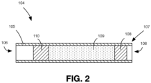
- Samples are loaded into the ring-down cavity 84 from a thermal desorption tube 104 that is used to collect the samples for testing.
- the absorption spectra for a set of samples to which the measured absorption spectra are at least indirectly compared are determined at this pressure and temperature to ensure consistency between these parameters which can affect the results.
- the pressure and temperature can be fixed at other levels for the known and measured absorption spectra.
- the gas inlet and auxiliary gas inlet valves 124a, 124b are in communication with a pathing valve 124e.
- the pathing valve 124e enables or disables direct access to a desorption tube line 120b and a sample outlet line 120c.
- the desorption tube line 120b includes a forward valve 124f and a rearward valve 124g.
- the thermal desorption tube 104 is positioned between the forward valve 124f and the rearward valve 124g, with the receiving end 107 of the thermal desorption tube 104 being positioned towards the rearward valve 124g.
- the thermal desorption tube 104 is positioned within a heater 132 that is controllable to heat the thermal desorption tube 104 to a range of temperatures.
- the sample outlet line 120c includes a sample outlet valve 124h and a mass flow controller 136.
- the sample-loading system 112 also has an outlet portion that includes a cavity outlet valve 124i in communication with the ring-down cavity 84.
- An outlet line 140 is in communication with the cavity outlet valve 124i.
- a pressure meter 144 is positioned along the outlet line 140.
- a vacuum cutoff valve 124j is positioned between the pressure meter 144 and a vacuum pump 148.
- a vacuum intake valve 124k is in communication with the vacuum pump 148 and draws air through a pump intake line 150.
- a filter 130b is positioned in the pump intake line 150 to inhibit entry of contaminants that can interfere with the working of the vacuum pump 148.
- Valves 124a to 124k may be alternatively referred to herein as valves 124.
- the cavity inlet valve 124d and the cavity outlet valve 124i are shown for convenience coupled to the ring-down cavity 84 at certain locations, it will be understood that the locations at which the valves 124d, 124i are coupled to the ring-down cavity 84 may vary.
- the cavity inlet valve 124d is in communication with the ring-down cavity 84 towards an end thereof adjacent the front cavity mirror 88a and the cavity outlet valve 124i is in communication with the ring-down cavity 84 towards an end thereof adjacent the rear cavity mirror 88b.
- the thermal desorption tube 104 containing the new sample is coupled to the sample-loading system 112 as shown in FIG. 1 .
- the vacuum intake valve 124k is opened and the vacuum pump 148 is turned on.
- the vacuum intake valve 124k is then closed, and the vacuum cutoff valve 124j, the cavity outlet valve 124i, the cavity inlet valve 124d, the gas intake line valve 124c, and the pathing valve 124e are opened in succession.
- the contents of the lines along this path and the ring-down cavity 84 are evacuated from the CRDS system 20 by the vacuum pump 148.
- the pressure meter 144 enables the determination of when the system has been evacuated sufficiently, especially when the pressure meter 128 is cut off from the vacuum pump 148.
- valves 124j, 124i, 124d, 124c, and 124e are then closed in the reverse order. Thereafter, during a nitrogen fill phase, valves 124a, 124c, 124d, 124i, and 124j are opened to allow nitrogen gas from the nitrogen gas source 116 to fill the lines 120a and 140. The nitrogen gas is then purged using another evacuation phase. The nitrogen fill phase and the evacuation phase can be repeated as desired to clear out the lines. The CRDS system 20 is thus evacuated of the previously tested sample.
- the thermal desorption tube 104 is flushed to remove carbon dioxide and water from the thermal desorption tube 104 so that the amount of carbon dioxide and water loaded into the ring-down cavity 84 is minimized.
- the gas intake valve 124a, the gas intake line valve 124c, and the rearward valve 124g are opened to give a path to the nitrogen gas to forward flush the thermal desorption tube 104.
- the thermal desorption tube 104 is selected to inhibit the collection of carbon dioxide and water with the sample, but there is still typically some carbon dioxide and water in the thermal desorption tube 104.
- 500ml of nitrogen gas is put through the thermal desorption tube to get out carbon dioxide and water that have remained in the thermal desorption tube 104 from the original sample. Then the forward valve 124f and the sample outlet valve 124h are opened to provide a path to the mass flow controller 136.
- the mass flow controller 136 allows the nitrogen gas and borne carbon dioxide and water to be released at a specified flow rate. In the present configuration, this flow rate is 500ml / min. All the valves 124 are then closed.
- the sample-loading system 112 is evacuated again using the same process discussed above to remove the nitrogen gas just introduced in the sample-loading system 112 lines.
- the heater 132 surrounding the thermal desorption tube 104 then heats the thermal desorption tube 104 to the desired temperature to thermally desorb the at least part of the new sample within the thermal desorption tube 104.
- the gas inlet valve 124a, the pathing valve 124e, the forward valve 124f, the rearward valve 124g, and the cavity inlet valve 124d are then opened to provide a direct path for the nitrogen gas from the nitrogen gas source 116, through the thermal desorption tube 104 having desorbed compounds of interest, and to the ring-down cavity 84.
- the gas inlet valve 124a is toggled open and closed by the system, then the system waits for the pressure reading at the pressure meter 128 to stabilize and reach one atmosphere. If, upon stabilization of the pressure meter 128, the pressure reading is still below one atmosphere, the gas inlet valve 124a is toggled again to repeat the process until the pressure reading is one atmosphere. When the pressure meter 128 shows that the pressure level in the ring-down cavity 84 is one atmosphere, the valves are all closed.
- the vacuum pump 148 is turned on, the cavity outlet valve 124i and the vacuum cutoff valve 124j are opened to evacuate the ring-down cavity 84. Then the cavity outlet valve 124i is closed before the desorption process is repeated.
- a full evacuation is generally not performed between multiple desorptions as there is still some of the sample between the rearward valve 124g and the cavity inlet valve 124d that would be otherwise lost.
- the surface area within the ring-down cavity to which compounds can adhere can be decreased in comparison to variable volume ring-down cavities that may be used to raise the pressure within the cavity to the desired level.
- the pressure meter 128 is upstream from the path of the sample from the thermal desorption tube 104 to the ring-down cavity 84, thereby preventing its contamination by the sample.
- FIG. 3 is a schematic diagram of an electronic control subsystem 200 for various components of the CRDS system 20 that are also illustrated. All of the lines represent electrical or electronic signals, with arrows representing unidirectional communications, setting of a voltage, etc., and lines that are not arrows representing bidirectional communications.
- a control module 204 including one or more processors acts as a computer system that controls the function of the various components illustrated in FIG. 1 .
- the control module 204 has one or more processors 205 and storage 206 storing computer-executable instructions that, when executed by the processor 205, cause the processor 205 to direct the other components of the CRDS system 20 as described herein.
- the control module 204 can be any type of component that includes at least one processor executing computer executable instructions to control operation of the other components of the CRDS system 20 as described herein.
- the DAQ generates output between 0V and 10V, and the high-voltage amplifier 220 multiplies the signal by 100 to generate a signal of 0V to 1000V to power the output coupler piezo 216.
- Each grating actuator 212 that changes the angle for the grating is driven by an actuator driver 228 that is given instructions by the control module 204 via RS-232.
- Each grating actuator 212 is moved so many millimeters, which is translated into a pitch angle of the laser 24, 28.
- Data signals from the pressure meters 128, 144 of the sample-loading system 112 are received through RS-232.
- the fast infrared detector 56 is connected to a small amplifier 232 and an oscilloscope 236 that can be used to read the amplitude and frequency of the beat signal that is used to tune the lasers 24, 28.
- a temperature controller 240 for the thermal desorption tube heater 132 is controlled via RS-232 by the control module 204.
- the tube heater 132 includes a temperature sensor and a piece of aluminum that has heating tape wrapped around it.
- the heating tape and the temperature sensor are both connected to the temperature controller 240 which is a PID (proportional integral derivative) controller.
- the PID controller sets and reads back the temperature via RS-232 to the main control module 204.
- a relay board 244 is connected to the control module 204 and is used to turn on and off all of the solenoid valves 124 and the vacuum pump 148.
- a three-channel piezo driver 248 drives piezo actuators 252 that actuate the micrometers 96b to adjust the length of the ring-down cavity 84.
- Each channel has two components: communications to the piezo driver through RS-232, and analog input from the DAQ card 224. In other embodiments, two or more piezo drivers can be employed.
- Each optical modulator 60, 68 is driven with an RF driver 256 that sends approximately a 40 MHz signal. Changing the frequency of the RF driver 256 changes the Bragg angle for a given optical wavelength, or changes the optical wavelength that a given or fixed Bragg angle is attuned to. If the RF driver 256 is tuned to a specific frequency and set to full power, most of the working beam 52 (about 85%) gets through. If adjusted to 80%, 70%, then the optical modulator 60, 68 will attenuate. If the RF driver 256 is set to zero, the optical modulator 60, 68 shuts off completely. The frequency of the RF driver 256 is set through a component via RS232.
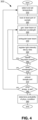
- a method 300 of analyzing a sample using the CRDS system 20 of FIG. 1 is shown in FIG. 4 .
- the sample to be analyzed using CRDS is desorbed at a single temperature.
- a part of a sample in a thermal desorption tube is first desorbed at a first temperature, and then at least one additional part of the sample is desorbed from the thermal desorption tube at at least one additional temperature.
- the set of ordered desorption temperatures thus can include a single desorption temperature or an ordered set of two or more desorption temperatures.
- the method 300 begins with the setting of the temperature of the heater 132 to a first of the ordered set of desorption temperatures (310).
- a set of one or more temperatures at which the sample is to be desorbed from the thermal desorption tube 104 can be ordered.
- the desorption temperatures are ordered from lowest to highest.
- the ordered set of desorption temperatures can include two desorption temperatures that are the same or similar.
- a first of the ordered set of desorption temperatures is selected, and the heater 132 is operated to heat the thermal desorption tube 104 to the first desorption temperature.
- the thermal desorption tube 104 is heated to the first desorption temperature via the heater 132, the part of the sample that has been desorbed at the first temperature is then loaded into the ring-down cavity 84, as previously described (320).
- a laser beam is generated by one of the lasers 24, 28 that is tuned to one of a set of wavelengths (330).
- the set of wavelengths can be selected from the wavelengths at which the lasers 24, 28 can produce a beam in any manner as desired.
- the generated laser beam is directed through the first optical modulator 60, reflected by the mirror 64, through the second optical modulator 68, and reflected by the mirror 72 into the ring-down chamber 80.
- the optical modulators 60, 68 attenuate the working beam 52 somewhat to modulate its intensity.
- the ring-down cavity 84 is not illuminated.
- the laser beam directed into the ring-down cavity 84 is extinguished (340).
- the laser beam entering the ring-down cavity 84 can be extinguished in a number of manners.
- the digitizer 264 sends a trigger pulse to the timing circuit 260 to cause the optical modulators 60, 68 to extinguish the laser light provided to the ring-down cavity 84.
- the laser can be turned off, or detuned so that it does not resonate for the configured cavity length, etc.
- the timing circuit 260 simultaneously directs the first and second optical modulators 60, 68 to attenuate the light beam at or close to an attenuation limits of the optical modulators 60, 68 to reduce an intensity of the light beam from the first optical modulator 60.
- the timing circuit 260 simultaneously directs the first and second optical modulators 60, 68 to attenuate the light beam at or close to an attenuation limits of the optical modulators 60, 68 to reduce an intensity of the light beam from the first optical modulator 60.
- the timing circuit 260 simultaneously directs the first and second optical modulators 60, 68 to attenuate the light beam at or close to an attenuation limits of the optical modulators 60, 68 to reduce an intensity of the light beam from the first optical modulator 60.
- the amount of light deflected by the first optical modulator 60 during the short span of time is markedly reduced by the second optical modulator 68 as it is shutting down.
- the second optical modular 68 greatly increases the attenuation achieved via the first optical modulator 60 alone.
- the first optical modulator 60 can attenuate by 30 dB
- the second optical modulator 68 can attenuate by an additional 30 dB, with the total attenuation achieved via the optical modulators 60, 68 being the sum of their attenuation, or 60 dB.
- the optical modulators 60, 68 attenuate the working beam 52 to modulate its intensity.
- each of the optical modulators 60, 68 attenuate the working beam 52 by 5 dB, for a total attenuation of 10dB.
- each of the optical modulators 60, 68 can still further attenuate the working beam 52 by 25 dB for a total further attenuation of 50 dB during the extinguishing of the working beam 52.
- one optical modulator would have to attenuate a working beam by 10 dB, leaving 20 dB of further attenuation available for extinguishing the working beam.
- the working beam 52 can be extinguished much more rapidly via 50 dB of further attenuation via the two optical modulators 60, 68 than with one optical modulator with 20 dB of further attenuation.
- the amount of additional light introduced into the ring-down cavity 84 after the optical modulators 60, 68 have been directed to shut down is a small fraction of the light further introduced by a single optical modulator setup in a conventional CRDS system.
- the measured decay of light in the ring-down cavity 84 is less affected by the additional light during the ramp-down times of the optical modulators 60, 68, thus granting higher precision when matching the observed decay times against known decay times.
- Extinguishing of the laser light provided to the ring-down cavity 84 commences a ring-down event.
- the resonating laser light provided to the ring-down cavity 84 can be extinguished in other manners in alternative embodiments, such as, for example, by detuning the laser.
- the ring-down event can be timed to occur during the peak while the ring-down cavity 84 is in resonance with the laser light, and not on one side of the peak. Further, as the bandwidth of the resonance is about 10 millivolts, the resolution of the piezo driver 248 is insufficiently granular to properly track the peak.
- the control module 204 registers light intensity decay data reported by the liquid nitrogen-cooled detector 100 exiting from the back end of the ring-down cavity 84 (350).
- the ring-down event lasts about ten microseconds in the present configuration, but can last a longer or shorter time in other embodiments.
- the light decay time is about two microseconds.
- the CRDS system 20 is configured to collected light intensity decay data for 500 ring-down events.
- the timing circuit 260 directs the optical modulators 60, 68 to recommence allowing the working beam 52 through to the ring-down cavity 84. If the light intensity decay data from 500 ring-down events has been captured, the control module 204 stops operation of the piezo driver 248, and then determines the decay rate from the ring-down event data, which refers to the light intensity decay data and may be used interchangeably herein. If, instead, it is determined at 360 that further light intensity decay data is to be collected, the control module 204 continues to direct the piezo driver 248 to actuate the rear cavity mirror 88b. As the aggregate voltage attains a maximum or minimum, it commences to proceed in an opposite direction.
- the aggregate voltage AV if the aggregate voltage AV was increasing prior to achieving the maximum voltage in its range, the aggregate voltage AV then decreases back towards the voltage corresponding with the resonance length RL. Alternatively, if the aggregate voltage AV was decreasing prior to achieving the minimum voltage in its range, the aggregate voltage AV then increases back towards the voltage corresponding with the resonance length RL. In this manner, ring-down events are triggered in both directions.
- the light intensity decay data is collected as quickly as possible, as various outputs can drift.
- the piezo actuators 252 can have a settling time referred to as piezo creep.
- any number of ring-down events can be employed at each wavelength and desorption temperature.
- the ring-down events at a wavelength and desorption temperature can be performed until a desired level of light intensity decay data has been collected.
- the light intensity decay data collected thus far can be quickly analyzed as it is collected to determine if it appears to be valid.
- the system can deem that sufficient data has been collected at that wavelength and desorption temperature. This can in many scenarios shorten the time required to perform the analysis.
- the light intensity decay data for the particular sample, desorption temperature, and wavelength may be processed by the control module 204, such as by determining a decay rate for each ring-down event and averaging these values. Other approaches can be employed to process the ring-down event data.
- the method 300 It is then determined if there are other wavelengths in the set at which the laser is to be generated (370). If there are other wavelengths to be generated, the method 300 returns to 330, at which the laser 24, 28 is tuned to generate a laser beam of the newly selected wavelength.
- the process is repeated for lights of other wavelengths to generate an absorption spectrum for the sample at the particular desorption temperature.
- the light intensity data from the liquid nitrogen-cooled detector 100 provides or is readily converted to, in effect, light intensity decay data that indicates how quickly the light of the particular wavelength was absorbed by the part of the sample that was loaded into the ring-down cavity 84.
- the light generated by the CO 2 laser 24 provides absorption coefficients for a range of wavelengths.
- absorption coefficients can be generated for a range of wavelengths for the light from the carbon-13 O2 laser 28. In this manner, an absorption spectrum can be developed for the sample.
- the part of the sample is unloaded from the ring-down cavity (375). It is determined if there are other temperatures in the ordered set to which the thermal desorption tube 104 is to be heated to desorb other parts of the sample for analysis in the ring-down cavity 84 (380). If it is determined that there are other temperatures at which a part of the sample is to be desorbed, the heater is set to the next desorption temperature at 310. In the present embodiment, a next desorption temperature to which the thermal desorption tube 104 is heated is higher than the previous desorption temperatures(s) to which the thermal desorption tube 104 was heated. If the ordered set of desorption temperatures includes a single desorption temperature, the method 300 does not return to 310.
- desorption of the sample contained in the thermal desorption tube 104 at another temperature that is higher than other temperatures at which the thermal desorption tube 104 was previously desorbed can yield a different subset of the compounds / substance in the sample.
- the CRDS system 20 analyzes the light intensity decay data for the set of wavelengths and the set of desorption temperatures to determine a probability that the patient from which the sample was drawn has a particular physiological condition or a degree of a physiological condition (390).
- the probability is determined at least indirectly using a dataset of light intensity decay data for previously analyzed samples for which the presence or absence of the physiological condition or a degree of the physiological condition (i.e., lung cancer in the exemplary embodiment) has been identified.
- the determination of the probability can use a predictive model that is at least partially based on the dataset of light intensity decay data for previously analyzed samples.
- the CRDS system 20 can determine the probability that the subject from which the analyzed sample was drawn has one of a set of discrete degrees of the physiological condition, and then present the most likely degree of the physiological condition or the entire set of probabilities. Further, the CRDS system 20 can also provide a confidence level for each of the results.
- the light intensity decay data collected at each desorption temperature can be analyzed at least indirectly using the dataset of light intensity decay data for the previously analyzed samples that is segregated by the same or similar desorption temperatures.
- the dataset of light intensity decay data for the previously analyzed samples was collected using the same or a similar sequence of temperatures for desorbing parts of the sample.
- the light intensity decay data from two or more desorption temperatures from the sample can be combined together, and analyzed using a predictive model generated at least partially based on light intensity decay data for previously analyzed samples that is treated in the same or similar manner (i.e., the light intensity decay data for corresponding desorption temperatures is aggregated).
- a predictive model can be generated from the dataset of light intensity decay data for the previously analyzed samples.
- One preferred approach is by using supervised machine learning.
- the dataset of light intensity decay data for previously analyzed samples represents spectra for entire parts of the previously collected samples and not any one particular volatile organic compound.
- the predictive model is generated using machine learning techniques at least partially by using the dataset of light intensity decay data as a training set.
- interpolation techniques such as spline interpolation, using neighboring absorbance values in the spectrum can be employed. If the available wavelengths are not evenly spaced, average values from comparable subjects identified by a k-nearest neighbor search can be used, as can a VOC regression approach to approximate missing values.
- Baseline correction can be used to eliminate any unwanted trends, such as via the use of common spectroscopy detrending techniques (e.g., linear, quadratic, and Savitzky-Golay detrending).
- Spectral subtraction techniques can also be employed for highly concentrated VOCs like acetone and ammonia, which are common to all subjects and may be masking small, important details in the spectra.
- a comprehensive analysis of the spectra and clinical factors is used to identify unobvious relationships and confounders in the dataset of light intensity decay data for previously analyzed samples to improve data interpretation and identify subgroups that are incorporated into the predictive model.
- breath VOC analysis There are a number of confounding factors in breath VOC analysis that include age, sex, smoking, alcohol consumption, medication use, and other diseases.
- Unsupervised clustering techniques, along with supervised predictive models that classify spectra according to possible confounders, are used to assess these factors.
- spectral data for different subgroups can be used to train separate models for lung cancer detection.
- spectral derivative-based features are being employed for feature extraction.
- Derivative-based features are particularly useful because they apply some inherent baseline and scale correction for inter-individual variability.
- Barcode features and a one-dimensional form of the local binary patterns (1D-LBP) can also be used.
- features derived from a time-series of desorptions of samples at different temperature sequences can also be employed.
- the various pre-processing and feature extraction methods can be combined, along with the information found in the confounding factor and subgroup analysis, to create the final classification system.
- a few feature selection techniques may be used.
- Statistics-based filter methods like minimum redundancy maximum relevance (“mRMR”) selection can be employed, as well as classification-based wrapper methods, like sequential feature selection (“SFS”) and genetic algorithm (“GA”) selection.
- SVM Simple support vector machine
- LDA and QDA discriminant analysis
- KNN classifiers can be employed to evaluate features in the wrapper selection methods and to build and validate the numerous classification models.
- FIG. 5 shows a method 400 for generating a predictive model.
- a set of desorption temperature sequences are identified for exploration.
- a sequence of desorption temperatures is an ordered set of temperatures to which the thermal description tube is heated to desorb parts of the sample contained therein. Desorption of the sample using a particular sequence of temperatures can enable different selective parts of the sample to be desorbed and analyzed separately, which can enable different aspects of the sample to be more readily identified. Certain features of a sample may be more readily apparent from the light intensity decay data captured for certain desorption temperature sequences.
- a first component/compound is desorbable from the thermal desorption tube 104 at a certain temperature and confounds a second component/compound that is desorbable at a slightly elevated temperature
- features of the light intensity decay data for a sample may become more apparent using a desorption temperature sequence that has a desorption temperature equal to that of the first component/compound, and then a subsequent desorption temperature equal to or above that of the second component/compound.
- the light intensity decay data registered at two desorption temperature sequences yield substantially equal correlations to the subset(s) of samples drawn from subjects having the physiological condition or a degree of the physiological condition, it may be desirable to select the shorter desorption temperature sequence, for example.
- the method 400 commenced with the selection of sample (404).
- the sample is selected from a set of samples from subjects that have been identified as one of having a physiological condition and not having the physiological condition.
- a desorption temperature sequence is selected from a set of desorption temperature sequences (408).
- the set of desorption temperature sequences can be chosen based on scientific evidence, randomly, etc.
- the desorption temperature of the heater 132 is set to the next desorption temperature in the sequence (412). If the sequence is yet unprocessed, the first desorption temperature in the sequence is selected.
- a part of the sample is then desorbed and loaded (416).
- the heater 132 is heated to the selected desorption temperature from the sequence and a part of the sample is desorbed.
- the sample-loading system 112 loads the desorbed part of the sample into the ring-down cavity 84.
- the control module 204 then operates one of the lasers 24, 28 to generate a laser beam of the selected wavelength.
- the laser beam is directed into the ring-down cavity 84 to "fill" the ring-down cavity 84 with light.
- control module 204 determines that there is sufficient light in the ring-down cavity 84, the control module 204 directs the optical modulators to extinguish the laser beam that is directed into the ring-down cavity 84 (424).
- the liquid nitrogen-cooled detector 100 registers the light intensity exiting the ring-down cavity 84 via the rear cavity mirror 88b (428).
- Light intensity decay data corresponds to the detected intensity of the light exiting the ring-down cavity 84 over time, and is transmitted to the control module 204.
- the control module 204 determines whether to repeat the ring-down event (430). The ring-down event may be repeated many times to reduce the effect of abnormalities. If another ring-down event is to be performed at the selected wavelength, the method 400 returns to 420, wherein a laser beam at the selected wavelength is generated. It is then determined if there are other wavelengths in the set to be used (432).
- the method 400 returns to 420, at which a laser beam is generated at the next selected wavelength. If, instead, it is determined that there are no other wavelengths in the set, it is determined if there is another desorption temperature in the sequence (436). If there is at least another desorption temperature in the sequence, the next desorption temperature in the sequence is selected and the heater 132 is heated to that temperature to desorb another part of the sample at 412.
- the correspondence between the light intensity decay data and the identification of the subjects from which the samples are drawn as having the physiological condition or degrees of the physiological condition for each desorption temperature sequence is then determined (448).
- the correspondence between the light intensity decay data and the identification of the samples as having the physiological condition or a degree of the physiological condition is stronger when there is a set of features that are significantly more prevalent in samples from subjects identified as having the physiological condition or a degree of the physiological condition.
- the light intensity decay data for the sequence of desorption temperatures may have a relatively good correlation to the presence or absence of the physiological condition in the subjects from which the samples are obtained. While this is an example, any pattern between the light intensity decay data and the presence of the physiological condition or a degree of the physiological condition can indicate the presence of a correlation between the light intensity decay data and the presence of the physiological condition or the degree of the physiological condition.
- a desorption temperature sequence is then selected based on the correspondence between the light intensity decay data and the identification of the subject from which the samples were drawn as having the physiological condition or a degree of the physiological condition for each desorption temperature sequence (452).
- the desorption temperature sequence may be selected entirely based on the measured correlation, or on the correlation in combination with other factors. Other factors can determine the selection of the sequence of desorption temperatures, such as the number of desorption temperatures in the sequence, thereby determining the amount of time to perform the analysis.
- a predictive model is then generated using the selected desorption temperature sequence at least partially selected based on the correlations (452).
- thermo desorption tube Where a sequence of temperatures is used to desorb a sample from a thermal desorption tube, it can be unadvantageous to analyze parts of samples that are desorbed at certain temperatures.
- the desorption may be performed at certain temperatures to remove substances that are less of interest than those desorbed at other temperatures.
- FIG. 6 shows a method 500 of analyzing a sample via CRDS.
- a part of the sample is desorbed at a first temperature and is, in effect, discarded as it may have little correlation to the presence or absence of a physiological condition in a patient.
- a second part of the sample is desorbed at a second temperature. The second part of the sample is deemed to have a relatively high correlation to the presence of the physiological condition or a degree of the physiological condition and is thus analyzed via CRDS.
- the method 500 commences with the setting of the temperature of the heater 132 at a first desorption temperature by the control module 204 (510). Heating of the heater 132 to the first desorption temperature causes the thermal desorption tube 104 to be heated and a first part of the sample to be desorbed.
- the sample-loading system 112 is then directed by the control module 204 to expel the first part of the sample without performing CRDS on the first part.
- the first part of the sample may be expelled to the surrounding atmosphere, to a collection cannister, or may be removed from the path between the thermal desorption tube 104 and the ring-down cavity 84 via any other suitable approach.
- the first sample is expelled through the mass flow controller 136 by closing valves 124b and 124d, and by opening valves 124a, 124c, 124g, 124f, and 124h, much in the same manner that carbon dioxide and water are expelled from the thermal desorption tube 104.
- the heater After expelling the first part of the sample, the heater is heated to a second desorption temperature (530).
- the second desorption temperature is generally higher than the first temperature and, as a result, causes different substances to be desorbed from the thermal desorption tube 104.
- the second desorption temperature is the same as or lower than the first desorption temperature. While a good portion of some components/compounds may have already been desorbed at the previous desorption temperature, virtually all of other confounding substances may have been desorbed as well, thus facilitating the isolation of these components/compounds.
- the second part of the sample is then loaded into the ring-down cavity 84 for analysis, as described above (540).
- the control module 204 operates one of the lasers 24, 28 to generate a laser beam at a selected wavelength (550).
- the laser beam is directed into the ring-down cavity 84 to fill the cavity with light. Once the ring-down cavity 84 is filled, the laser beam is extinguished (560).
- the liquid nitrogen-cooled detector 100 registers the intensity of the light exiting the ring-down cavity 84 via the rear cavity mirror 88b (570).
- the light exiting the ring-down cavity 84 represents light intensity decay data that is registered by the liquid nitrogen-cooled detector 100 and transmitted to the control module 204.
- the ring-down event it is determined whether to repeat the ring-down event again (580). As noted above, it can be desirable to repeat the ring-down event a number of times and then determine one or more collective metrics by determining a decay rate for the light intensity decay data for each ring-down and then averaging the decay rates to minimize the effect of aberrations. If another ring-down event is to be repeated, a laser beam is generated at the selected wavelength at 550. If, instead, no more ring-down events are to be performed, it is determined whether there are other wavelengths in the set of wavelengths to be analyzed (590). If it is determined that there are other wavelengths to be analyzed, a laser beam of a next one of the wavelengths is generated at 550. If, instead, there are no more wavelengths to generate a laser beam at for performing CRDS, the light intensity decay data collected at 570 is then analyzed (595), after which the method 500 ends. The collected light intensity decay data is then analyzed.
- At least one processor that analyzes the light intensity decay data and generates a predictive model is shown and described as being fully integrated with the other elements of the CRDS system, in other embodiments, one or more of the at least one processor can be provided in a separate computer system that has storage and performs some or all of the functionality of the control module in the above-described and illustrated embodiment.
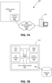
- FIG. 7A shows a system 600 for analyzing a sample using CRDS in another embodiment.
- the system 600 includes a CRDS system 604 similar to that of FIG. 1 .
- the CRDS system 604 has a control module 608 that has at least one processor for controlling operation of the various elements of the CRDS system 604.
- the control module 608 is in communication with a computer system 612 over a data communications network 616.
- the computer system 612 can be any single computer or multiple computers coupled together locally and/or remotely to provide the described functionality.
- the data communications network 616 can be any suitable medium enabling the control module 608 and the computer system 612 to communicate at least the light intensity decay data and any associated parameters associated therewith, such as wavelengths, the temperature at which the at least part of the sample was desorbed, as well as any other subject-specific data, such as the above-noted confounding factors, a subject identifier, time and location information for when and where the sample was analyzed, etc.
- FIG. 7B shows a number of physical and logical components of the computer system 612, including a central processing unit (“CPU”) 624, random access memory (“RAM”) 628, an input/output (“I/O") interface 632, a communications interface 636, non-volatile storage 640, and a local bus 644 enabling the CPU 624 to communicate with the other components.
- the CPU 624 can include one or more processors and executes at least an operating system, as well as a spectra evaluation application.
- the RAM 628 provides relatively responsive volatile storage to the CPU 624.
- the I/O interface 632 allows for input to be received from one or more devices, such as a keyboard, a mouse, etc., and outputs information to output devices, such as a display and/or speakers.
- the communications interface 636 permits communication with other computing devices like the control module 608 over computer networks such as the data communications network 616.
- the non-volatile storage 640 stores the operating system and programs, including computer-executable instructions for implementing the spectra evaluation application. During operation of the computer system 612, the operating system, the programs and the data may be retrieved from the non-volatile storage 640 and placed in RAM 628 to facilitate execution.
- the light sources are two lasers that produce light in the mid-infrared range
- other light sources can be employed.
- a laser producing light in the visible spectrum or a near-infrared laser can be employed.
- the CRDS system can include only one laser, or three or more lasers, to generate the working beam.
- Electro-optic modulators can be used in place of acousto-optic modulators.
- the acousto-optic modulators can be configured so that the frequency of the working beam is shifted up or down. As long as the net frequency shift effected by the acousto-optic modulators shifts the frequency of the working beam significantly away from the frequency of the working beam being generated by the laser(s) so that the reflected light is outside of the bandwidth of the laser light being generated, the amount of interference between the reflected light and the generated working beam can be minimized.
- more than two optical modulators can be employed in a CRDS system to provide further extinguishing capacity to more quickly extinguish the working beam at the commencement of a ring-down event.
- a single optical modulator can be employed.
- One or more focusing lenses can be employed in other embodiments, and translated to enable repositioning of the lenses to allow mode-matching of each wavelength of the lasers.
- Analysis of the samples can be performed at pressure levels other than one atmosphere in other embodiments.
- the breadth of the absorption spectrum may change accordingly.
Landscapes
- Physics & Mathematics (AREA)
- Spectroscopy & Molecular Physics (AREA)
- Health & Medical Sciences (AREA)
- Life Sciences & Earth Sciences (AREA)
- General Physics & Mathematics (AREA)
- Chemical & Material Sciences (AREA)
- Analytical Chemistry (AREA)
- Biochemistry (AREA)
- General Health & Medical Sciences (AREA)
- Immunology (AREA)
- Pathology (AREA)
- Engineering & Computer Science (AREA)
- Molecular Biology (AREA)
- Biomedical Technology (AREA)
- Optics & Photonics (AREA)
- Biophysics (AREA)
- Hematology (AREA)
- Urology & Nephrology (AREA)
- Food Science & Technology (AREA)
- Medicinal Chemistry (AREA)
- Investigating Or Analysing Materials By Optical Means (AREA)
- Lasers (AREA)
- Investigating, Analyzing Materials By Fluorescence Or Luminescence (AREA)
- Optical Measuring Cells (AREA)
Claims (12)
- Verfahren (300) zum Analysieren einer Probe unter Verwendung der Resonatorabklingzeitspektroskopie, umfassend:Desorbieren eines ersten Teils einer Probe aus einem thermischen Desorptionsrohr (104), das auf eine erste Desorptionstemperatur (310) erhitzt ist, um den ersten Teil der Probe in einen Abklingresonator (84) zu laden (320);für jeden eines ersten Satzes von Wellenlängen:Erzeugen, über mindestens einen Laser (24, 28), eines mit der Wellenlänge (330) in den Abklingresonator (84) gerichteten Laserstrahls;Auslöschen des in den Abklingresonator (84) eintretenden Laserstrahls (340); undRegistrieren von Lichtintensitätsabfalldaten (350) für das aus dem Abklingresonator (84) austretende Licht über ein Lichtintensitätssensorsystem (100);Laden eines zweiten Teils der Probe (320), der aus dem thermischen Desorptionsrohr (104) desorbiert wurde, das auf eine zweite Desorptionstemperatur (310) erhitzt ist;für jeden eines zweiten Satzes von Wellenlängen:Erzeugen, über den mindestens einen Laser (24, 28), eines mit der Wellenlänge (330) in den Abklingresonator (84) gerichteten Laserstrahls;Auslöschen des in den Abklingresonator (84) eintretenden Laserstrahls (340); undRegistrieren von Lichtintensitätsabfalldaten (350) für das aus dem Abklingresonator (84) austretende Licht über ein Lichtintensitätssensorsystem (100);Bestimmen (390), über mindestens einen Prozessor (205, 624), einer Wahrscheinlichkeit aus den Lichtintensitätsabfalldaten unter Verwendung eines Vorhersagemodells, das zumindest teilweise auf dem Datensatz von Lichtintensitätsabfalldaten für den ersten Satz von Wellenlängen und den zweiten Satz von Wellenlängen basiert, dass ein Subjekt, von dem die Probe erhalten wurde, einen physiologischen Zustand oder einen Grad eines physiologischen Zustands aufweist, zumindest indirekt unter Verwendung eines Datensatzes von Lichtintensitätsabfalldaten für zuvor analysierte Proben, für die das Vorhandensein oder die Abwesenheit des physiologischen Zustands oder der Grad des physiologischen Zustands identifiziert worden ist.
- Verfahren nach Anspruch 1, wobei der physiologische Zustand Lungenkrebs ist.
- Verfahren nach Anspruch 2, wobei die Probe und die zuvor analysierten Proben Atemproben sind.
- Verfahren nach Anspruch 1, wobei der zweite Satz von Wellenlängen dem ersten Satz von Wellenlängen entspricht.
- Verfahren nach Anspruch 4, ferner umfassend:
Kombinieren der Lichtintensitätsabfalldaten aus dem zweiten Teil der Probe mit den Lichtintensitätsabfalldaten aus dem ersten Teil der Probe für jeden des ersten Satzes von Wellenlängen. - Verfahren nach Anspruch 1, wobei das Bestimmen unter Verwendung eines Vorhersagemodells durchgeführt wird, das zumindest teilweise unter Verwendung des Datensatzes von Lichtintensitätsabfalldaten für zuvor analysierte Proben trainiert wurde.
- Verfahren nach Anspruch 1, wobei das Erzeugen, das Auslöschen und das Registrieren durchgeführt werden, bis ein Steuermodul (204) bestimmt, dass ein gewünschtes Niveau von Lichtintensitätsabfalldaten erfasst worden ist.
- System (20) zum Analysieren einer Probe unter Verwendung der Resonatorabklingzeitspektroskopie, umfassend:einen Abklingresonator (84);mindestens einen Laser (24, 28), der betriebsfähig ist, um einen Laserstrahl bei jedem eines ersten Satzes von Wellenlängen zu erzeugen, wobei der Laserstrahl in den Abklingresonator (84) gerichtet wird;ein Probenladesystem (112) zum Laden eines ersten Teils einer Probe aus einem thermischen Desorptionsrohr (104) in den Abklingresonator (84) zur Analyse und zum Entladen des ersten Teils der Probe aus dem Abklingresonator (84);ein Lichtintensitätssensorsystem (100), das positioniert ist, um Lichtintensitätsabfalldaten für das aus dem Abklingresonator (84) austretende Licht zu registrieren;mindestens einen Prozessor (205, 624), der betriebsfähig mit dem Probenladesystem (112), dem mindestens einen Laser (24, 28) und dem Lichtintensitätssensorsystem (100) gekoppelt ist;einen Speicher (206, 640), der computerlesbare Anweisungen speichert, die, wenn sie von dem mindestens einen Prozessor (205, 624) ausgeführt werden, den mindestens einen Prozessor (205, 624) zu Folgendem veranlassen:Steuern des Probenladesystems (112), um den ersten Teil der Probe zu desorbieren, indem das thermische Desorptionsrohr (104) auf eine erste Desorptionstemperatur erhitzt wird, um den ersten Teil der Probe in den Abklingresonator (84) zu laden;für jeden des ersten Satzes von Wellenlängen:Betreiben des mindestens einen Lasers (24, 28), um den in den Abklingresonator (84) gerichteten Laserstrahl zu erzeugen;Auslöschen des in den Abklingresonator (84) eintretenden Laserstrahls; undRegistrieren von Lichtintensitätsabfalldaten für das aus dem Abklingresonator (84) austretende Licht über das Lichtintensitätssensorsystem (100);Steuern des Probenladesystems (112), um einen zweiten Teil der Probe zu desorbieren, indem das thermische Desorptionsrohr (104) auf eine zweite Desorptionstemperatur erhitzt wird, um den zweiten Teil der Probe in den Abklingresonator (84) zu laden, nachdem der erste Teil der Probe aus dem Abklingresonator (84) entladen wurde,für jeden eines zweiten Satzes von Wellenlängen:Betreiben des mindestens einen Lasers (24, 28), um den in den Abklingresonator (84) gerichteten Laserstrahl zu erzeugen;Auslöschen des in den Abklingresonator (84) eintretenden Laserstrahls; undRegistrieren von Lichtintensitätsabfalldaten für das aus dem Abklingresonator (84) austretende Licht über das Lichtintensitätssensorsystem (100); undBestimmen einer Wahrscheinlichkeit aus den Lichtintensitätsabfalldaten für den ersten Satz von Wellenlängen, dass ein Subjekt, von dem die Probe erhalten wurde, einen physiologischen Zustand oder einen Grad eines physiologischen Zustands aufweist, zumindest indirekt unter Verwendung eines Vorhersagemodells, das zumindest teilweise auf einem Datensatz von Lichtintensitätsabfalldaten für zuvor analysierte Proben basiert, für die das Vorhandensein oder die Abwesenheit des physiologischen Zustands oder der Grad des physiologischen Zustands identifiziert worden ist.
- System nach Anspruch 8, wobei der physiologische Zustand Lungenkrebs ist.
- System nach Anspruch 9, wobei die Probe und die zuvor analysierten Proben Atemproben sind.
- System nach Anspruch 8, wobei der zweite Satz von Wellenlängen dem ersten Satz von Wellenlängen entspricht.
- System nach Anspruch 11, wobei der mindestens eine Prozessor die Lichtintensitätsabfalldaten aus dem zweiten Teil der Probe mit den Lichtintensitätsabfalldaten aus dem ersten Teil der Probe für jeden des ersten Satzes von Wellenlängen kombiniert.
Applications Claiming Priority (3)
| Application Number | Priority Date | Filing Date | Title |
|---|---|---|---|
| US201962828750P | 2019-04-03 | 2019-04-03 | |
| US16/740,026 US11105739B2 (en) | 2019-04-03 | 2020-01-10 | Method and system for analyzing a sample using cavity ring-down spectroscopy, and a method for generating a predictive model |
| PCT/CA2020/050250 WO2020198843A1 (en) | 2019-04-03 | 2020-02-26 | Method and system for analyzing a sample using cavity ring-down spectroscopy, and a method for generating a predictive model |
Publications (3)
| Publication Number | Publication Date |
|---|---|
| EP3948227A1 EP3948227A1 (de) | 2022-02-09 |
| EP3948227A4 EP3948227A4 (de) | 2022-12-28 |
| EP3948227B1 true EP3948227B1 (de) | 2025-04-23 |
Family
ID=72662108
Family Applications (4)
| Application Number | Title | Priority Date | Filing Date |
|---|---|---|---|
| EP20782958.1A Active EP3948227B1 (de) | 2019-04-03 | 2020-02-26 | Verfahren und system zur analyse einer probe unter verwendung von cavity-ring-down-spektroskopie |
| EP20784463.0A Active EP3948228B1 (de) | 2019-04-03 | 2020-02-26 | Spektroskopiesystem und verfahren zur durchführung von spektroskopie |
| EP20785123.9A Active EP3948235B1 (de) | 2019-04-03 | 2020-02-26 | Cavity-ring-down-spektroskopiesystem und verfahren zur modulation eines lichtstrahls darin |
| EP20782842.7A Pending EP3948234A4 (de) | 2019-04-03 | 2020-02-26 | Verfahren zur abstimmung eines resonanzhohlraums und hohlraumring-abwärtsspektrskopiesystem |
Family Applications After (3)
| Application Number | Title | Priority Date | Filing Date |
|---|---|---|---|
| EP20784463.0A Active EP3948228B1 (de) | 2019-04-03 | 2020-02-26 | Spektroskopiesystem und verfahren zur durchführung von spektroskopie |
| EP20785123.9A Active EP3948235B1 (de) | 2019-04-03 | 2020-02-26 | Cavity-ring-down-spektroskopiesystem und verfahren zur modulation eines lichtstrahls darin |
| EP20782842.7A Pending EP3948234A4 (de) | 2019-04-03 | 2020-02-26 | Verfahren zur abstimmung eines resonanzhohlraums und hohlraumring-abwärtsspektrskopiesystem |
Country Status (7)
| Country | Link |
|---|---|
| US (6) | US11035789B2 (de) |
| EP (4) | EP3948227B1 (de) |
| JP (5) | JP7695199B2 (de) |
| CN (4) | CN113924472B (de) |
| AU (6) | AU2020251718A1 (de) |
| CA (4) | CA3135520A1 (de) |
| WO (4) | WO2020198841A1 (de) |
Families Citing this family (10)
| Publication number | Priority date | Publication date | Assignee | Title |
|---|---|---|---|---|
| US11035789B2 (en) * | 2019-04-03 | 2021-06-15 | Picomole Inc. | Cavity ring-down spectroscopy system and method of modulating a light beam therein |
| KR20230029906A (ko) * | 2020-06-26 | 2023-03-03 | 스피라체크 리미티드 | 휘발성 유기 화합물 캡쳐링 장치 |
| US20230215569A1 (en) * | 2022-01-04 | 2023-07-06 | Opteev Technologies, Inc. | Systems and methods for detecting diseases based on the presence of volatile organic compounds in the breath |
| CN114839159B (zh) * | 2022-04-13 | 2023-06-02 | 中国空气动力研究与发展中心超高速空气动力研究所 | 兼容腔增强技术和腔衰荡技术的谐振腔吸收光谱测量方法 |
| CN115117723B (zh) * | 2022-06-24 | 2025-04-08 | 中国科学院光电技术研究所 | 一种基于腔镜光斑形态监测的调腔方法 |
| CN115663582B (zh) * | 2022-09-22 | 2026-03-31 | 重庆大学 | 一种抑制强干扰的频率锁定反馈相位动态调节方法 |
| EP4375725A1 (de) * | 2022-11-28 | 2024-05-29 | Alpine Quantum Technologies GmbH | Evakuierter optischer hohlraum |
| JP2024179792A (ja) * | 2023-06-16 | 2024-12-26 | 株式会社島津製作所 | ガス吸収分光装置 |
| US20250323468A1 (en) * | 2024-04-12 | 2025-10-16 | Blue Laser Fusion, Inc. | Optical enhancement cavity with a cavity dumper device using an acoustic wave |
| CN118603149B (zh) * | 2024-08-07 | 2024-12-03 | 中国科学院精密测量科学与技术创新研究院 | 一种用于原子干涉传感器的集成化光学系统 |
Family Cites Families (258)
| Publication number | Priority date | Publication date | Assignee | Title |
|---|---|---|---|---|
| BE624177A (de) | 1961-10-30 | |||
| US3453557A (en) | 1965-03-15 | 1969-07-01 | Laser Inc | Laser stabilization apparatus |
| US3517330A (en) | 1966-11-09 | 1970-06-23 | Philco Ford Corp | Frequency stabilization of laser system which compares the amplitudes of two beat note signals |
| US3534289A (en) | 1967-02-06 | 1970-10-13 | Xerox Corp | Laser system with optical discriminator |
| US3431514A (en) | 1967-12-29 | 1969-03-04 | Sylvania Electric Prod | Laser frequency stabilization |
| US3628173A (en) | 1969-04-28 | 1971-12-14 | Bell Telephone Labor Inc | Laser mode selection and stabilization apparatus employing a birefringement etalon |
| GB1282659A (en) * | 1969-09-12 | 1972-07-19 | Hewlett Packard Co | Atomic fluorescence spectroscopy system |
| US3596201A (en) | 1970-06-08 | 1971-07-27 | Hughes Aircraft Co | Frequency stabilized laser |
| US3733129A (en) | 1971-02-01 | 1973-05-15 | Hughes Aircraft Co | Laser distance detector |
| DE2130331C3 (de) | 1971-06-18 | 1978-06-29 | Erwin Sick Gmbh Optik-Elektronik, 7808 Waldkirch | Verfahren und Vorrichtung zur Bestimmung der Konzentrationen der Komponenten eines aus zwei Gasen und Rauch bestehenden Gemisches |
| GB1366235A (en) * | 1972-05-18 | 1974-09-11 | Sagami Chem Res | Method for measuring nitrogen oxides in pollution air and device for performing the same method |
| DE2723939C2 (de) | 1977-05-24 | 1983-01-05 | Hans-Jörg Dr.rer.nat. 8520 Erlangen Albrecht | Vorrichtung zur Atemgasanalyse |
| US4197513A (en) | 1977-12-09 | 1980-04-08 | Quanta Ray Inc. | Active Q-switched high power single mode laser |
| US4475199A (en) | 1980-06-02 | 1984-10-02 | Litton Systems, Inc. | Zeeman multioscillator ring laser gyro insensitive to magnetic fields and detuning frequencies |
| US4468773A (en) | 1981-05-29 | 1984-08-28 | Seaton Norman T | Laser control apparatus and method |
| US4410271A (en) | 1981-06-15 | 1983-10-18 | Matthews Thomas G | Multiple-reflection optical gas cell |
| US4672618A (en) | 1983-03-07 | 1987-06-09 | Beckman Instruments, Inc. | Laser stabilization servo system |
| US4779279A (en) | 1984-03-05 | 1988-10-18 | Beckman Instruments, Inc. | Magnetic laser control |
| GB8427912D0 (en) * | 1984-11-05 | 1984-12-12 | Crosfield Electronics Ltd | Matching beam modulators |
| US4648714A (en) | 1985-09-11 | 1987-03-10 | University Of Utah | Molecular gas analysis by Raman scattering in intracavity laser configuration |
| US4784486A (en) | 1987-10-06 | 1988-11-15 | Albion Instruments | Multi-channel molecular gas analysis by laser-activated Raman light scattering |
| DE3819333A1 (de) | 1988-06-07 | 1989-12-14 | Siemens Ag | Laseranordnung mit hoher frequenz- und intensitaetsstabilitaet der laserstrahlung |
| DE3819687A1 (de) | 1988-06-09 | 1989-12-14 | Siemens Ag | Gaslaseranordnung mit frequenzstabilisierung |
| US5014278A (en) | 1988-09-22 | 1991-05-07 | Ushio Denki Kabushiki Kaisha | Method for the frequency stabilization of internal mirror type helium-neon laser oscillating at wavelength of 543 nm |
| JPH0338614A (ja) * | 1989-07-05 | 1991-02-19 | Pioneer Electron Corp | 音響光学変調装置 |
| US5054027A (en) | 1989-10-10 | 1991-10-01 | Massachusetts Institute Of Technology | Pulsed laser |
| US5029174A (en) | 1989-12-05 | 1991-07-02 | Spectra-Physics, Inc. | Intermodulation product stabilized laser |
| FR2658367B1 (fr) | 1990-02-13 | 1992-06-05 | Sagem | Laser fournissant deux ondes a des frequences differentes. |
| US5135304A (en) | 1990-05-11 | 1992-08-04 | Boc Health Care, Inc. | Gas analysis system having buffer gas inputs to protect associated optical elements |
| US5636035A (en) | 1991-09-30 | 1997-06-03 | The Trustees Of The Stevens Institute Of Technology | Method and apparatus for dual modulation laser spectroscopy |
| DE69219580T2 (de) | 1992-02-24 | 1997-09-11 | Hewlett Packard Co | Ramanspektroskopie von Atemgasen |
| US5341206A (en) | 1992-12-03 | 1994-08-23 | Hewlett-Packard Company | Method for calibrating a spectrograph for gaseous samples |
| GB2276973A (en) | 1993-03-20 | 1994-10-12 | Gec Ferranti Defence Syst | A pulsed laser |
| JP3838671B2 (ja) | 1993-10-25 | 2006-10-25 | アークレイ株式会社 | 呼気採取装置 |
| US5386833A (en) | 1993-12-23 | 1995-02-07 | Biochem International, Inc. | Method for calibrating a carbon dioxide monitor |
| US5465728A (en) | 1994-01-11 | 1995-11-14 | Phillips; Michael | Breath collection |
| US5528040A (en) | 1994-11-07 | 1996-06-18 | Trustees Of Princeton University | Ring-down cavity spectroscopy cell using continuous wave excitation for trace species detection |
| DE19615333A1 (de) * | 1995-07-24 | 1997-01-30 | Hewlett Packard Co | Gasanalysator mit einer Anordnung zur Sprühreinigung eines optischen Elements |
| EP1669738A3 (de) | 1996-10-09 | 2007-12-12 | Symyx Technologies, Inc. | Infrarotspektroskopie und Abbildung von Bibliotheken |
| DE19723208A1 (de) * | 1997-06-03 | 1998-12-10 | Ldt Gmbh & Co | Vorrichtung zum Intensitätsmodulieren eines Lichtbündels, ein Herstellungsverfahren für diese, ein Verfahren zum Intensitätsmodulieren eines Lichtbündels sowie Verwendungen von der Vorrichtung |
| US5912740A (en) | 1997-06-20 | 1999-06-15 | The Board Of Trustees Of The Leland Stanford Junior University | Ring resonant cavities for spectroscopy |
| US5903358A (en) | 1997-06-20 | 1999-05-11 | The Board Of Trustees Of The Leland Stanford Junior University | Spectroscopy using active diode laser stabilization by optical feedback |
| US5815277A (en) | 1997-06-20 | 1998-09-29 | The Board Of Trustees Of The Leland Stanford Junior Univesity | Deflecting light into resonant cavities for spectroscopy |
| US6076392A (en) | 1997-08-18 | 2000-06-20 | Metasensors, Inc. | Method and apparatus for real time gas analysis |
| US6494079B1 (en) | 2001-03-07 | 2002-12-17 | Symyx Technologies, Inc. | Method and apparatus for characterizing materials by using a mechanical resonator |
| US6172823B1 (en) * | 1997-10-21 | 2001-01-09 | Trustees Of Princeton University | Mode matching for cavity ring-down spectroscopy based upon Brewster's angle prism retroreflectors |
| US6084682A (en) | 1998-04-15 | 2000-07-04 | The Board Of Trustees Of The Leland Stanford Junior University | Cavity-locked ring down spectroscopy |
| FR2778244B1 (fr) | 1998-04-30 | 2000-07-13 | Univ Joseph Fourier | Procede d'excitation d'une cavite optique pour la detection de gaz a l'etat de traces |
| FR2778573B1 (fr) | 1998-05-13 | 2000-09-22 | Technomed Medical Systems | Reglage de frequence dans un appareil de traitement par ultrasons focalises de haute intensite |
| US6466322B1 (en) | 1998-12-31 | 2002-10-15 | The Board Of Trustees Of The Leland Stanford Junior University | Swept continuous wave cavity ring-down spectroscopy |
| US6540691B1 (en) | 1999-01-12 | 2003-04-01 | Michael Phillips | Breath test for the detection of various diseases |
| US6233052B1 (en) | 1999-03-19 | 2001-05-15 | The Board Of Trustees Of The Leland Stanford Junior University | Analog detection for cavity lifetime spectroscopy |
| US6479019B1 (en) | 1999-04-15 | 2002-11-12 | Quantum Group, Inc. | Sensor and sensor assembly for detecting a target gas in a breath sample |
| JP4384331B2 (ja) * | 1999-07-15 | 2009-12-16 | 新日本製鐵株式会社 | 流通性に優れる赤外線吸収分析計用測定セル及び赤外線吸収分析装置 |
| US6363772B1 (en) | 1999-12-10 | 2002-04-02 | Quadrivium, L.L.C. | System and method for detection of a biological condition |
| JP2001194299A (ja) | 2000-01-11 | 2001-07-19 | Board Of Trustees For The Leland Stanford Junior Univ | キャビティリングダウン分光システムおよび方法 |
| US6324191B1 (en) | 2000-01-12 | 2001-11-27 | Intralase Corp. | Oscillator with mode control |
| US6727492B1 (en) * | 2000-01-13 | 2004-04-27 | Regents Of The University Of Colorado | Cavity ringdown spectroscopy system using differential heterodyne detection |
| US6952945B2 (en) | 2000-01-25 | 2005-10-11 | The State Of Oregon Acting By And Through The State Board Of Higher Education On Behalf Of Portland State University | Method and apparatus for concentrating samples for analysis |
| US6633596B1 (en) | 2000-05-31 | 2003-10-14 | University Corporation For Atmospheric Research | Frequency stable pulsed laser |
| EP1307714A4 (de) * | 2000-07-12 | 2007-04-04 | Macquarie Res Ltd | Optische heterodyndetektion bei der otpischen cavity-ringdown-spektroskopie |
| US7113814B2 (en) | 2000-07-13 | 2006-09-26 | Virginia Commonwealth University | Tissue interrogation spectroscopy |
| JP2002090259A (ja) * | 2000-09-19 | 2002-03-27 | Anritsu Corp | 半導体レーザ光源装置及び光周波数領域反射測定装置 |
| US6658034B2 (en) * | 2000-12-13 | 2003-12-02 | Picarro, Inc. | Surface-emitting semiconductor laser |
| WO2002031467A1 (en) | 2000-10-12 | 2002-04-18 | Amnis Corporation | Multipass cavity for illumination and excitation of moving objects |
| US7004909B1 (en) | 2001-03-19 | 2006-02-28 | Pranalytica, Inc. | Diagnostic method for high sensitivity detection of component concentrations in human gas emissions |
| US7616123B2 (en) | 2001-04-11 | 2009-11-10 | Trutouch Technologies, Inc. | Apparatus and method for noninvasively monitoring for the presence of alcohol or substances of abuse in controlled environments |
| GB0120027D0 (en) | 2001-08-16 | 2001-10-10 | Isis Innovation | Spectroscopic breath analysis |
| US20040190563A1 (en) | 2001-08-21 | 2004-09-30 | Gendron Denis J. | Suppression of mode-beating noise in a q-switched pulsed laser using novel q-switch device |
| US6816636B2 (en) * | 2001-09-12 | 2004-11-09 | Honeywell International Inc. | Tunable optical filter |
| US20070133001A1 (en) | 2001-09-12 | 2007-06-14 | Honeywell International Inc. | Laser sensor having a block ring activity |
| US6582376B2 (en) | 2001-09-13 | 2003-06-24 | Pranalytica, Inc. | Alveolar breath collection device and method |
| US7606274B2 (en) | 2001-09-20 | 2009-10-20 | The Uab Research Foundation | Mid-IR instrument for analyzing a gaseous sample and method for using the same |
| FR2830617B1 (fr) | 2001-10-10 | 2004-01-30 | Univ Joseph Fourier | Dispositif a laser couple a une cavite par retroaction optique pour la detection de traces de gaz |
| SE524086C2 (sv) | 2001-10-30 | 2004-06-22 | Phase In Ab | Mäthuvud för gasanalysator |
| DE10156149A1 (de) | 2001-11-15 | 2003-06-05 | Manfred Muertz | Apparatur zur Atemanalyse |
| US8224426B2 (en) * | 2001-11-20 | 2012-07-17 | University Health Network | Optical transillumination and reflectance spectroscopy to quantify disease risk |
| US6726637B2 (en) | 2001-12-06 | 2004-04-27 | Michael Phillips | Breath collection apparatus |
| US7318909B2 (en) | 2001-12-12 | 2008-01-15 | Trustees Of Princeton University | Method and apparatus for enhanced evanescent field exposure in an optical fiber resonator for spectroscopic detection and measurement of trace species |
| AU2003207732A1 (en) * | 2002-01-28 | 2003-09-02 | Cidra Corporation | Multifunctional optical device having a spatial light modulator with an array of micromirrors |
| US7153272B2 (en) | 2002-01-29 | 2006-12-26 | Nanotherapeutics, Inc. | Methods of collecting and analyzing human breath |
| IL148468A (en) | 2002-03-03 | 2012-12-31 | Exalenz Bioscience Ltd | Breath collection system |
| US7101340B1 (en) * | 2002-04-12 | 2006-09-05 | Braun Charles L | Spectroscopic breath profile analysis device and uses thereof for facilitating diagnosis of medical conditions |
| US6958446B2 (en) | 2002-04-17 | 2005-10-25 | Agilent Technologies, Inc. | Compliant and hermetic solder seal |
| EP1329999B1 (de) | 2002-08-03 | 2004-04-07 | Agilent Technologies Inc. (a Delaware Corporation) | Wellenlängenabstimmbarer Laser mit einem diffraktiven optischen Element |
| US7352463B2 (en) | 2002-09-06 | 2008-04-01 | Tdw Delaware, Inc. | Method and device for detecting gases by absorption spectroscopy |
| CN100464178C (zh) | 2002-09-06 | 2009-02-25 | Tdw特拉华有限公司 | 利用吸收光谱法检测气体的方法 |
| US6865198B2 (en) | 2002-09-27 | 2005-03-08 | Battelle Memorial Institute | Cavity ringdown spectroscopy system and method |
| US20040142484A1 (en) | 2002-09-30 | 2004-07-22 | Intel Corporation | Spectroscopic analysis system and method |
| US20040137637A1 (en) * | 2003-01-13 | 2004-07-15 | Chuji Wang | Breath gas analyzer for diagnosing diabetes and method of use thereof |
| WO2004073497A2 (en) | 2003-02-14 | 2004-09-02 | The Charlotte-Mecklenburg Hospital Authority | Device and method for collection of exhaled alveolar breath condensate |
| US7054008B2 (en) * | 2003-02-19 | 2006-05-30 | Mississippi State University | Method and apparatus for elemental and isotope measurements and diagnostics-microwave induced plasma-cavity ring-down spectroscopy |
| US20050062972A1 (en) | 2003-09-22 | 2005-03-24 | Krusen Calvin R. | System and method for cavity ring-down spectroscopy using continuously varying continuous wave excitation |
| US7113286B2 (en) | 2003-12-03 | 2006-09-26 | Tiger Optics, Llc | Apparatus and method for improved analysis of liquids by continuous wave-cavity ring down spectroscopy |
| US7154595B2 (en) | 2003-12-17 | 2006-12-26 | Picarro, Inc. | Cavity enhanced optical detector |
| ATE522012T1 (de) | 2003-12-18 | 2011-09-15 | Yeda Res & Dev | Laserresonatoranordnung |
| FR2864622B1 (fr) | 2003-12-26 | 2006-09-22 | Commissariat Energie Atomique | Procede et dispositif de mesure d'absorption ou de diffusion lumineuse d'elements biologiques |
| US7069769B2 (en) * | 2004-01-20 | 2006-07-04 | Academia Sinica | Ultraviolet photoacoustic ozone detection |
| CN100546133C (zh) | 2004-02-04 | 2009-09-30 | 日本电信电话株式会社 | 锁模激光光源及利用其的多载波光源 |
| US20050177057A1 (en) | 2004-02-05 | 2005-08-11 | Mitchell Friedman | Automated breath collection device |
| GB0405554D0 (en) | 2004-03-12 | 2004-04-21 | Xyz Imaging Inc | A laser |
| GB0405820D0 (en) | 2004-03-15 | 2004-04-21 | Evanesco Ltd | Time resolved and multiplexed cavity sensing apparatus and methods |
| US7106763B2 (en) | 2004-03-18 | 2006-09-12 | Picarro, Inc. | Wavelength control for cavity ringdown spectrometer |
| US7277526B2 (en) * | 2004-04-09 | 2007-10-02 | Lyncean Technologies, Inc. | Apparatus, system, and method for high flux, compact compton x-ray source |
| US7902534B2 (en) | 2004-09-28 | 2011-03-08 | Honeywell International Inc. | Cavity ring down system having a common input/output port |
| EP1806581A4 (de) | 2004-10-28 | 2011-08-17 | Seems Inc | Krankheitsdiagnosesystem |
| US7646485B2 (en) | 2004-12-02 | 2010-01-12 | Picarro, Inc. | Method and apparatus for enhancing the accuracy of CRDS measurements |
| CA2590216C (en) * | 2004-12-17 | 2011-08-02 | Honeywell Analytics Ag | Optical gas detection |
| US20060132766A1 (en) * | 2004-12-21 | 2006-06-22 | Bruce Richman | Continuously tunable external cavity diode laser |
| JP2006189392A (ja) | 2005-01-07 | 2006-07-20 | Hamamatsu Photonics Kk | 吸収計測装置 |
| JP4522882B2 (ja) | 2005-02-15 | 2010-08-11 | 浜松ホトニクス株式会社 | 吸収計測装置 |
| US20060200037A1 (en) | 2005-03-02 | 2006-09-07 | Falasco Marianne R | System and method for selectively collecting exhaled air |
| JP2006267047A (ja) * | 2005-03-25 | 2006-10-05 | Toshiba Corp | レーザー光を利用した物質検出装置及びその方法 |
| JP2008536333A (ja) | 2005-04-13 | 2008-09-04 | コーニング インコーポレイテッド | 同調可能外部キャビティレーザのためのモード整合システム |
| JP2007019361A (ja) | 2005-07-11 | 2007-01-25 | Mitsutoyo Corp | 周波数安定化レーザ |
| GB0515883D0 (en) | 2005-08-02 | 2005-09-07 | Geola Technologies Ltd | Stabilized laser cavity |
| US7569823B2 (en) | 2006-11-10 | 2009-08-04 | The George Washington University | Compact near-IR and mid-IR cavity ring down spectroscopy device |
| US7541586B2 (en) | 2006-11-10 | 2009-06-02 | The George Washington University | Compact near-IR and mid-IR cavity ring down spectroscopy device |
| US8903474B2 (en) | 2005-12-06 | 2014-12-02 | Pen Inc. | Analysis of gases |
| CA2640717A1 (en) | 2006-02-03 | 2007-08-09 | Otsuka Pharmaceutical Co., Ltd. | Method of exhaled gas measuring and analysis and apparatus therefor |
| US7538881B2 (en) * | 2006-02-17 | 2009-05-26 | The Regents Of The University Of Colorado, A Body Corporate | Frequency comb cavity enhanced spectroscopy |
| US7535573B2 (en) * | 2006-02-23 | 2009-05-19 | Picarro, Inc. | Cavity enhanced optical spectroscopy with a cavity having a predetermined deviation from a mode degeneracy condition |
| US7777886B2 (en) | 2006-02-23 | 2010-08-17 | Picarro, Inc. | Optical system including a weak lens and a beam translation plate for selectively coupling to the lowest order mode of an optical resonator |
| US8018981B2 (en) | 2006-04-12 | 2011-09-13 | Li-Cor, Inc. | Multi-pass optical cell with actuator for actuating a reflective surface |
| KR100754402B1 (ko) * | 2006-05-16 | 2007-08-31 | 삼성전자주식회사 | 수직외부공진기형 면발광 레이저 |
| WO2007142644A1 (en) * | 2006-06-08 | 2007-12-13 | Braun Charles L | Spectroscopic breath profile analysis device and uses thereof for facilitating diagnosis of medical conditions |
| CN101506644B (zh) * | 2006-08-31 | 2011-05-18 | 皇家飞利浦电子股份有限公司 | 具有可变光强调制器的光学腔增强性的光声示踪气体检测器 |
| US8109128B2 (en) * | 2006-08-31 | 2012-02-07 | Koninklijke Philips Electronics N.V. | Cavity-enhanced photo acoustic trace gas detector with improved feedback loop |
| CN101512317A (zh) * | 2006-08-31 | 2009-08-19 | 皇家飞利浦电子股份有限公司 | 具有光学功率增强腔的稳定光声示踪气体探测器 |
| JP4897449B2 (ja) | 2006-12-04 | 2012-03-14 | 株式会社ミツトヨ | レーザ周波数安定化装置、レーザ周波数安定化方法、及びレーザ周波数安定化プログラム |
| JP2008145248A (ja) | 2006-12-08 | 2008-06-26 | Yokowo Co Ltd | 中継コネクタ |
| CA2671122C (en) | 2006-12-18 | 2013-05-07 | John Cormier | Apparatus and method for rapid and accurate quantification of an unknown, complex mixture |
| US7612885B2 (en) | 2006-12-22 | 2009-11-03 | Honeywell International Inc | Spectroscopy method and apparatus for detecting low concentration gases |
| US7620082B2 (en) | 2007-01-17 | 2009-11-17 | The Regents Of The University Of California | Method and apparatus for seeding and stabilizing an optical device |
| CN101261181B (zh) * | 2008-01-04 | 2010-06-16 | 中国科学院光电技术研究所 | 一种用于测量高反射率的装置 |
| US7486398B1 (en) * | 2008-02-05 | 2009-02-03 | Honeywell International Inc. | Groundwater monitoring system and method |
| JP2009218488A (ja) | 2008-03-12 | 2009-09-24 | Mitsutoyo Corp | レーザ周波数安定化装置、方法、及びプログラム |
| CN101261182B (zh) | 2008-03-26 | 2010-06-23 | 中国科学院光电技术研究所 | 基于频率选择性光反馈光腔衰荡技术的高反射率测量方法 |
| CN201210139Y (zh) * | 2008-05-27 | 2009-03-18 | 杭州电子科技大学 | 一种连续锁模近场光腔衰荡光谱分析装置 |
| US7970025B2 (en) | 2008-07-03 | 2011-06-28 | The United States Of America As Represented By The Administrator Of The National Aeronautics And Space Administration | System and method for tuning adjusting the central frequency of a laser while maintaining frequency stabilization to an external reference |
| US20120143805A1 (en) | 2008-09-09 | 2012-06-07 | Somalogic, Inc. | Cancer Biomarkers and Uses Thereof |
| US8254418B2 (en) | 2008-09-19 | 2012-08-28 | Inphase Technologies, Inc. | Method for finding and tracking single-mode operation point of external cavity diode lasers |
| US8040518B2 (en) * | 2008-10-07 | 2011-10-18 | Entanglement Technologies, Inc. | Cavity enhanced trace gas detection gradiometer |
| US9044565B2 (en) | 2008-10-30 | 2015-06-02 | Oridion Medical (1987) Ltd. | Oral-nasal cannula system enabling CO2 and breath flow measurement |
| US20120016818A1 (en) * | 2008-10-31 | 2012-01-19 | Mark Hackett | Classification of Biological Samples Using Spectroscopic Analysis |
| GB0821188D0 (en) | 2008-11-19 | 2008-12-24 | Isis Innovation | Measurment of gas concentrations in breath |
| FR2938916B1 (fr) * | 2008-11-24 | 2012-10-19 | Ap2E | Dispositif d'echantillonnage de gaz. |
| WO2010079491A1 (en) | 2009-01-09 | 2010-07-15 | Technion Research And Development Foundation Ltd. | Volatile organic compounds as diagnostic markers in the breath for lung cancer |
| US8488639B1 (en) | 2009-02-04 | 2013-07-16 | Stc.Unm | Systems and methods having a frequency comb |
| US8846407B2 (en) | 2009-02-10 | 2014-09-30 | James M. Hargrove | Chemical explosive detector |
| US20110283770A1 (en) | 2009-02-10 | 2011-11-24 | Hok Instrument Ab | Breath analysis |
| JP5695302B2 (ja) | 2009-04-03 | 2015-04-01 | 理研計器株式会社 | 複合型マルチパスセルおよびガス測定器 |
| CN102224404B (zh) | 2009-06-02 | 2013-03-27 | 松下电器产业株式会社 | 化学物质检测方法 |
| US8564785B2 (en) * | 2009-09-18 | 2013-10-22 | The United States of America, as represented by the Secretary of Commerce, The National Institute of Standards and Technology | Comb-based spectroscopy with synchronous sampling for real-time averaging |
| FR2950489B1 (fr) | 2009-09-23 | 2012-08-10 | Univ Paris 6 Pierre Et Marie Curie | Procede de stabilisation de la longueur d'une cavite optique |
| GB0920315D0 (en) | 2009-11-20 | 2010-01-06 | Univ Bristol | A diagnostic apparatus |
| GB2476452A (en) | 2009-12-14 | 2011-06-29 | Univ Bruxelles | Transverse laser mode switching |
| US9335605B2 (en) * | 2010-01-25 | 2016-05-10 | Washington University | Iteration of optical time reversal by ultrasonic encoding in biological tissue |
| JP5537174B2 (ja) | 2010-01-29 | 2014-07-02 | 株式会社四国総合研究所 | ガス濃度測定装置 |
| US8327686B2 (en) * | 2010-03-02 | 2012-12-11 | Li-Cor, Inc. | Method and apparatus for the photo-acoustic identification and quantification of analyte species in a gaseous or liquid medium |
| US9643186B1 (en) | 2010-03-19 | 2017-05-09 | Invoy Technologies, Llc | Breath analysis system, device and method employing nanoparticle-based sensor |
| WO2011117572A1 (en) | 2010-03-25 | 2011-09-29 | Isis Innovation Limited | Analysis of breath |
| CA2796450C (en) | 2010-04-16 | 2016-10-25 | C-Lock Inc. | Method and system for monitoring and reducing ruminant methane production |
| US20110295140A1 (en) | 2010-05-28 | 2011-12-01 | Intelliscience Research Llc | Method and Apparatus for Measuring Trace Levels of CO in Human Breath Using Cavity Enhanced, Mid-Infared Absorption Spectroscopy |
| US8437000B2 (en) * | 2010-06-29 | 2013-05-07 | Honeywell International Inc. | Multiple wavelength cavity ring down gas sensor |
| WO2012004794A1 (en) | 2010-07-06 | 2012-01-12 | Pulmone Advanced Medical Devices, Ltd. | Methods and apparatus for the measurement of pulmonary parameters |
| US9086421B1 (en) | 2010-07-29 | 2015-07-21 | Entanglement Technologies, Inc. | Device and method for cavity detected high-speed diffusion chromatography |
| JP6022456B2 (ja) | 2010-08-20 | 2016-11-09 | ニューサウス イノベーションズ ピーティーワイ リミテッド | 時間領域信号の減衰定数を決定する方法とシステム |
| US20120103062A1 (en) | 2010-11-02 | 2012-05-03 | Picarro, Inc. | Sample preparation for gas analysis using inductive heating |
| GB201018711D0 (en) | 2010-11-05 | 2010-12-22 | Univ Manchester | Apparatus and methods for breath sampling |
| US20120183949A1 (en) | 2011-01-19 | 2012-07-19 | Searete Llc, A Limited Liability Corporation Of The State Of Delaware | Method, device, or system using lung sensor for detecting a physiological condition in a vertebrate subject |
| US20120268709A1 (en) * | 2011-04-20 | 2012-10-25 | Zilkie Aaron J | Tunable optical filters with liquid crystal resonators |
| US9592360B2 (en) | 2011-04-22 | 2017-03-14 | Inogen, Inc. | Gas concentrator with removable cartridge adsorbent beds |
| US8453601B2 (en) | 2011-05-19 | 2013-06-04 | C-Lock Inc. | Vaccine and health-related applications for ruminant breath monitoring system |
| WO2013003429A1 (en) | 2011-06-28 | 2013-01-03 | Ikaria, Inc. | End-tidal gas monitoring apparatus |
| US20130011872A1 (en) * | 2011-07-05 | 2013-01-10 | Gabriel Philip M | Stable isotopic biomarker measurement for the detection of cancer and the determination of efficacy of treatment in diagnosed cancer patients |
| US8665442B2 (en) | 2011-08-18 | 2014-03-04 | Li-Cor, Inc. | Cavity enhanced laser based isotopic gas analyzer |
| US8659759B2 (en) | 2011-08-25 | 2014-02-25 | Li-Cor, Inc. | Laser based cavity enhanced optical absorption gas analyzer |
| JP5859793B2 (ja) | 2011-09-28 | 2016-02-16 | 株式会社ミツトヨ | 光出力信号の安定化判定方法、及びレーザ周波数安定化装置 |
| US8659758B2 (en) | 2011-10-04 | 2014-02-25 | Li-Cor, Inc. | Laser based cavity enhanced optical absorption gas analyzer with laser feedback optimization |
| US9014221B2 (en) | 2011-11-14 | 2015-04-21 | The United States Of America, As Represented By The Secretary Of The Navy | Infrared laser |
| US9212990B1 (en) | 2011-12-06 | 2015-12-15 | Zybertec Llc | System and methods for molecular detection using intracavity laser absorption spectroscopy |
| BR112014015145B1 (pt) | 2011-12-21 | 2022-08-16 | Capnia, Inc. | Aparelho para analisar uma concentração de gás em uma respiração de um paciente e método para determinar uma concentração de um gás em uma respiração de um paciente |
| EP3871599A1 (de) | 2011-12-22 | 2021-09-01 | Circassia Ab | Probenahmevorrichtung |
| US20140276100A1 (en) | 2012-02-01 | 2014-09-18 | Invoy Technologies | System for measuring breath analytes |
| US8642982B2 (en) * | 2012-03-16 | 2014-02-04 | The United States of America, as represented by the Secretary of Commerce, NIST | Fast switching arbitrary frequency light source for broadband spectroscopic applications |
| WO2013148757A1 (en) * | 2012-03-29 | 2013-10-03 | Imra America, Inc. | Methods for precision optical frequency synthesis and molecular detection |
| GB201207881D0 (en) | 2012-05-04 | 2012-06-20 | Isis Innovation | Active chemical sensing using optical microcavity |
| US9204821B2 (en) | 2012-05-09 | 2015-12-08 | Isense Medical Corp. | Method of and apparatus for detecting upper respiratory bacterial infection from exhaled mammalian breath and colorimetric sensor array cartridge |
| US9625702B2 (en) | 2012-05-17 | 2017-04-18 | Joseph T. Hodges | Coupled cavity spectrometer with enhanced sensitivity and dynamic range |
| US9097583B2 (en) | 2012-05-22 | 2015-08-04 | Los Gatos Research | Long-path infrared spectrometer |
| CN102798631B (zh) | 2012-09-10 | 2014-03-26 | 重庆大学 | 一种用于肺癌呼出气体检测的可见光检测装置 |
| CN102841082B (zh) | 2012-09-10 | 2014-08-20 | 重庆大学 | 双信号肺癌呼出气体检测系统 |
| US9241670B2 (en) * | 2012-09-11 | 2016-01-26 | Covidien Lp | Methods and systems for conditioning physiological information using a normalization technique |
| BR112015008725A2 (pt) | 2012-10-19 | 2017-07-04 | Avisa Pharma Inc | método para determinar a presença ou ausência de uma infecção bacteriana em um indivíduo |
| EP2914953B1 (de) | 2012-11-02 | 2020-03-25 | Li-Cor, Inc. | Resonanzverstärkte laserbasierte gasanalysatorsysteme und verfahren |
| US8885167B2 (en) * | 2012-11-02 | 2014-11-11 | Li-Cor, Inc. | Cavity enhanced laser based gas analyzer systems and methods |
| US9194742B2 (en) * | 2012-11-02 | 2015-11-24 | Li-Cor, Inc. | Cavity enhanced laser based gas analyzer systems and methods |
| US10499819B2 (en) | 2013-01-08 | 2019-12-10 | Capnia, Inc. | Breath selection for analysis |
| DK2948761T3 (da) | 2013-01-23 | 2023-09-04 | California Inst Of Techn | Indstilleligt miniaturelaserspektrometer til registrering af en sporgas |
| US9121838B2 (en) | 2013-02-25 | 2015-09-01 | King Abdullah University Of Science And Technology | Ammonia sensor using wavelength modulation spectroscopy |
| US9200960B2 (en) | 2013-04-26 | 2015-12-01 | Entanglement Technologies, Inc. | Cavity enhanced absorption spectroscopy with a laser modulation side-band frequency locked to the cavity |
| US9768347B2 (en) | 2013-04-26 | 2017-09-19 | Agency For Science, Technology And Research | High speed surface plasmon coupled light emitting diodes |
| US8982352B1 (en) | 2013-06-11 | 2015-03-17 | Picarro, Inc. | Regular, stable optical frequency scale for cavity enhanced optical spectroscopy |
| DE102013215640A1 (de) | 2013-08-08 | 2015-02-12 | Siemens Aktiengesellschaft | Anordnung zur Entnahme von Atemgasproben |
| US9207121B2 (en) * | 2013-09-11 | 2015-12-08 | Tiger Optics, Llc | Cavity-enhanced frequency comb spectroscopy system employing a prism cavity |
| CN104458603A (zh) * | 2013-09-23 | 2015-03-25 | 苏州青山生物科技有限公司 | 一种新型幽门螺杆菌检测方法、装置及其应用 |
| CN103487402B (zh) * | 2013-10-14 | 2015-09-02 | 北京信息科技大学 | 带有饱和吸收光纤的环形腔内腔光纤激光器气体检测系统 |
| US9653877B1 (en) * | 2013-11-08 | 2017-05-16 | Stc.Unm | Nested frequency combs |
| JP6512666B2 (ja) | 2013-11-13 | 2019-05-15 | ダンマークス テクニスク ユニバーシテットDanmarks Tekniske Universitet | 圧縮光パルスの発生方法 |
| CA2939937A1 (en) | 2014-03-04 | 2015-09-11 | University Of Florida Research Foundation | Medication adherence monitoring device |
| US9778110B1 (en) | 2014-04-17 | 2017-10-03 | Picarro, Inc. | Self-referencing cavity enhanced spectroscopy (SRCES) systems and methods |
| US20150335206A1 (en) | 2014-04-28 | 2015-11-26 | Safeway Safety Step, Llc | Bathtub systems and methods |
| CA2893178C (en) | 2014-05-22 | 2021-04-20 | Picomole Instruments Inc. | Method and apparatus for non-invasive detection of conditions such as lung cancer |
| US10925515B2 (en) | 2014-05-22 | 2021-02-23 | Picomole Inc. | Alveolar breath collection apparatus |
| CA2892870C (en) | 2014-05-22 | 2020-10-27 | Picomole Instruments Inc. | Alveolar breath collection apparatus |
| CN104251841A (zh) * | 2014-07-01 | 2014-12-31 | 中国医学科学院生物医学工程研究所 | 基于光腔衰荡光谱的多样本呼吸分析仪 |
| US9568465B2 (en) | 2014-08-21 | 2017-02-14 | Sharp Kabushiki Kaisha | Breath analyser and detection methods |
| WO2016040354A1 (en) * | 2014-09-08 | 2016-03-17 | Li-Cor, Inc. | Ultra stable resonant cavities for gas analysis systems |
| WO2016061533A1 (en) | 2014-10-17 | 2016-04-21 | Digital Ally, Inc. | Breath analyzer, system, and computer program for authenticating, preserving, and presenting breath analysis data |
| US10241037B2 (en) * | 2014-10-21 | 2019-03-26 | Colorado State University Research Foundation | Laser sensor for trace gas detection |
| ES2712200T3 (es) | 2014-12-23 | 2019-05-09 | Max Planck Gesellschaft | Método para medir una respuesta de muestra espectral |
| US20160313233A1 (en) * | 2015-04-23 | 2016-10-27 | National Institute Of Standards And Technology | Photoacoustic spectrometer for nondestructive aerosol absorption spectroscopy |
| US9755399B2 (en) * | 2015-05-05 | 2017-09-05 | Boreal Laser Inc. | Packaged laser thermal control system |
| US10067126B2 (en) * | 2015-05-25 | 2018-09-04 | Hunan SkyWorld Biotechnologies Co. LTD | Use of fluorescence for the quick and easy determination of s-adenosylmethionine, s-adenosylhomocysteine and homocysteine |
| US10627335B2 (en) | 2015-07-13 | 2020-04-21 | Riken | Structure for use in infrared spectroscopy and infrared spectroscopy method using same |
| KR101633466B1 (ko) * | 2015-07-15 | 2016-06-24 | 한국과학기술원 | 광빗에서 직접적으로 추출된 광모드를 이용하여 펨토초레이저의 광빗이 갖는 전체적 주파수의 안정화를 구현하는 장치 및 방법 |
| WO2017014097A1 (ja) | 2015-07-17 | 2017-01-26 | コニカミノルタ株式会社 | ガス検知装置およびガス検知方法 |
| CN205484001U (zh) * | 2015-08-20 | 2016-08-17 | 苏州华和呼吸气体分析研究所有限公司 | 一种实时在线监测脂肪燃烧的便携式丙酮呼吸分析仪 |
| US10226201B2 (en) | 2015-10-29 | 2019-03-12 | Invoy Holdings, Llc | Flow regulation device for breath analysis and related method |
| US10333183B2 (en) | 2016-01-07 | 2019-06-25 | Hulico LLC | Relithiation in oxidizing conditions |
| JP6792778B2 (ja) * | 2016-03-02 | 2020-12-02 | 国立大学法人東海国立大学機構 | 炭素同位体分析装置および炭素同位体分析方法 |
| WO2017156321A1 (en) * | 2016-03-10 | 2017-09-14 | Li-Cor, Inc. | Multiple laser optical feedback assisted cavity enhanced absorption spectoscopy systems and methods |
| CN109310368A (zh) | 2016-04-25 | 2019-02-05 | 奥斯通医疗有限公司 | 用于捕获呼吸样本的系统和设备 |
| US10079467B2 (en) | 2016-06-27 | 2018-09-18 | The United States Of America, As Represented By The Secretary Of Commerce | Optomechanical laser for dynamic measurement |
| WO2018039417A1 (en) * | 2016-08-24 | 2018-03-01 | The Research Foundation For The State University Of New York | Apparatus and method for cavity-enhanced ultrafast two-dimensional spectroscopy |
| US10775297B2 (en) | 2016-08-24 | 2020-09-15 | Ecotec Solutions, Inc. | Laser absorption spectroscopy system and method for discrimination of a first and a second gas |
| US10067050B2 (en) | 2016-12-05 | 2018-09-04 | The United States Of America, As Represented By The Secretary Of Commerce | Linear absorption spectrometer to optically determine an absolute mole fraction of radiocarbon in a sample |
| FI127556B (en) | 2017-02-06 | 2018-09-14 | Teknologian Tutkimuskeskus Vtt Oy | Method and Device for Respiratory Analysis |
| CN106981552B (zh) | 2017-02-15 | 2019-04-12 | 华灿光电(浙江)有限公司 | 一种发光二极管的芯片及其制作方法 |
| BR112019016708B1 (pt) | 2017-02-27 | 2024-01-30 | Third Pole, Inc | Sistemas de geração de óxido nítrico |
| CN106877168B (zh) | 2017-03-07 | 2019-08-02 | 中国科学院国家授时中心 | 一种基于eom和pzt的光学共振腔的锁定装置 |
| CA2998026A1 (en) | 2017-03-13 | 2018-09-13 | Picomole Inc. | Apparatus and method of optimizing laser system |
| CN106908389B (zh) | 2017-03-17 | 2018-02-16 | 哈尔滨翰奥科技有限公司 | 气体传感器及用于检测氟化氢气体浓度变化的方法 |
| CN107037003A (zh) | 2017-05-04 | 2017-08-11 | 南昌航空大学 | 一种基于光腔衰荡光谱技术检测高纯气体中水汽含量的系统 |
| US10527492B2 (en) | 2017-05-16 | 2020-01-07 | Li-Cor, Inc. | Mode matching method for absorption spectroscopy systems |
| US10168275B2 (en) | 2017-05-23 | 2019-01-01 | International Business Machines Corporation | Untuned resonance traced gas sensing |
| JP6764829B2 (ja) | 2017-06-01 | 2020-10-07 | 株式会社Joled | 表示パネルの制御装置、表示装置および表示パネルの駆動方法 |
| GB201709922D0 (en) | 2017-06-21 | 2017-08-02 | Redwave Labs Ltd | Optical device |
| US10330592B2 (en) | 2017-07-21 | 2019-06-25 | Serguei Koulikov | Laser absorption spectroscopy isotopic gas analyzer |
| CN109596524B (zh) | 2017-10-03 | 2024-04-26 | 株式会社堀场制作所 | 多重反射池及其构成方法和气体分析装置 |
| WO2019074922A1 (en) | 2017-10-10 | 2019-04-18 | Endo Medical, Inc. | BREATH ANALYSIS DEVICE |
| CA2997070A1 (en) | 2018-03-02 | 2019-09-02 | Picomole Inc. | Alveolar breath collection apparatus |
| WO2019176115A1 (ja) * | 2018-03-16 | 2019-09-19 | 光トライオード株式会社 | 吸光分析装置 |
| JP6730373B2 (ja) | 2018-06-12 | 2020-07-29 | 大陽日酸株式会社 | 光多重反射容器 |
| US11289276B2 (en) | 2018-10-30 | 2022-03-29 | Global Advanced Metals Japan K.K. | Porous metal foil and capacitor anodes made therefrom and methods of making same |
| CN109856054A (zh) | 2019-03-26 | 2019-06-07 | 北京市燃气集团有限责任公司 | 一种腔衰荡光谱的检测装置 |
| US11035789B2 (en) * | 2019-04-03 | 2021-06-15 | Picomole Inc. | Cavity ring-down spectroscopy system and method of modulating a light beam therein |
-
2019
- 2019-07-11 US US16/509,207 patent/US11035789B2/en active Active
- 2019-09-09 US US16/564,662 patent/US10921246B2/en active Active
- 2019-10-11 US US16/599,943 patent/US11499916B2/en active Active
-
2020
- 2020-01-10 US US16/740,026 patent/US11105739B2/en active Active
- 2020-02-26 WO PCT/CA2020/050248 patent/WO2020198841A1/en not_active Ceased
- 2020-02-26 CA CA3135520A patent/CA3135520A1/en active Pending
- 2020-02-26 EP EP20782958.1A patent/EP3948227B1/de active Active
- 2020-02-26 WO PCT/CA2020/050250 patent/WO2020198843A1/en not_active Ceased
- 2020-02-26 EP EP20784463.0A patent/EP3948228B1/de active Active
- 2020-02-26 CN CN202080039579.6A patent/CN113924472B/zh active Active
- 2020-02-26 CN CN202080039573.9A patent/CN114008441B/zh active Active
- 2020-02-26 AU AU2020251718A patent/AU2020251718A1/en not_active Abandoned
- 2020-02-26 AU AU2020254714A patent/AU2020254714A1/en not_active Abandoned
- 2020-02-26 CA CA3135503A patent/CA3135503A1/en active Pending
- 2020-02-26 CA CA3135501A patent/CA3135501A1/en active Pending
- 2020-02-26 AU AU2020252975A patent/AU2020252975B2/en active Active
- 2020-02-26 WO PCT/CA2020/050249 patent/WO2020198842A1/en not_active Ceased
- 2020-02-26 JP JP2021560524A patent/JP7695199B2/ja active Active
- 2020-02-26 WO PCT/CA2020/050252 patent/WO2020198844A1/en not_active Ceased
- 2020-02-26 JP JP2021560417A patent/JP7603607B2/ja active Active
- 2020-02-26 CN CN202080040052.5A patent/CN113950619B/zh active Active
- 2020-02-26 CN CN202080039490.XA patent/CN113924471B/zh active Active
- 2020-02-26 JP JP2021560520A patent/JP2022529253A/ja active Pending
- 2020-02-26 AU AU2020251067A patent/AU2020251067A1/en not_active Abandoned
- 2020-02-26 EP EP20785123.9A patent/EP3948235B1/de active Active
- 2020-02-26 CA CA3135504A patent/CA3135504A1/en active Pending
- 2020-02-26 JP JP2021560533A patent/JP2022529621A/ja active Pending
- 2020-02-26 EP EP20782842.7A patent/EP3948234A4/de active Pending
-
2021
- 2021-01-28 US US17/160,791 patent/US11506601B2/en active Active
- 2021-07-28 US US17/443,873 patent/US11788957B2/en active Active
-
2024
- 2024-02-27 JP JP2024027391A patent/JP7807476B2/ja active Active
-
2025
- 2025-12-01 AU AU2025271542A patent/AU2025271542A1/en active Pending
- 2025-12-01 AU AU2025271541A patent/AU2025271541A1/en active Pending
Also Published As
Similar Documents
| Publication | Publication Date | Title |
|---|---|---|
| EP3948227B1 (de) | Verfahren und system zur analyse einer probe unter verwendung von cavity-ring-down-spektroskopie | |
| US20110295140A1 (en) | Method and Apparatus for Measuring Trace Levels of CO in Human Breath Using Cavity Enhanced, Mid-Infared Absorption Spectroscopy | |
| JPWO2016063918A1 (ja) | ガス分析装置、ガス分析方法、メタボローム解析方法およびデータベース | |
| US20250290849A1 (en) | Spectroscopic apparatus and gas detection apparatus | |
| JPH05161628A (ja) | 患者のグルコース濃度を非侵襲的に測定する方法 |
Legal Events
| Date | Code | Title | Description |
|---|---|---|---|
| STAA | Information on the status of an ep patent application or granted ep patent |
Free format text: STATUS: THE INTERNATIONAL PUBLICATION HAS BEEN MADE |
|
| PUAI | Public reference made under article 153(3) epc to a published international application that has entered the european phase |
Free format text: ORIGINAL CODE: 0009012 |
|
| STAA | Information on the status of an ep patent application or granted ep patent |
Free format text: STATUS: REQUEST FOR EXAMINATION WAS MADE |
|
| 17P | Request for examination filed |
Effective date: 20211102 |
|
| AK | Designated contracting states |
Kind code of ref document: A1 Designated state(s): AL AT BE BG CH CY CZ DE DK EE ES FI FR GB GR HR HU IE IS IT LI LT LU LV MC MK MT NL NO PL PT RO RS SE SI SK SM TR |
|
| DAV | Request for validation of the european patent (deleted) | ||
| DAX | Request for extension of the european patent (deleted) | ||
| A4 | Supplementary search report drawn up and despatched |
Effective date: 20221130 |
|
| RIC1 | Information provided on ipc code assigned before grant |
Ipc: G06N 20/00 20190101ALN20221124BHEP Ipc: G01N 33/497 20060101ALI20221124BHEP Ipc: G01N 21/39 20060101AFI20221124BHEP |
|
| REG | Reference to a national code |
Ref country code: DE Ref legal event code: R079 Free format text: PREVIOUS MAIN CLASS: G01N0021250000 Ipc: G01N0021390000 Ref document number: 602020050018 Country of ref document: DE |
|
| GRAP | Despatch of communication of intention to grant a patent |
Free format text: ORIGINAL CODE: EPIDOSNIGR1 |
|
| STAA | Information on the status of an ep patent application or granted ep patent |
Free format text: STATUS: GRANT OF PATENT IS INTENDED |
|
| RIC1 | Information provided on ipc code assigned before grant |
Ipc: G01N 1/22 20060101ALN20240521BHEP Ipc: G06N 20/00 20190101ALN20240521BHEP Ipc: G01N 33/497 20060101ALI20240521BHEP Ipc: G01N 21/39 20060101AFI20240521BHEP |
|
| INTG | Intention to grant announced |
Effective date: 20240612 |
|
| RAP3 | Party data changed (applicant data changed or rights of an application transferred) |
Owner name: BREATHE BIOMEDICAL INC. |
|
| GRAJ | Information related to disapproval of communication of intention to grant by the applicant or resumption of examination proceedings by the epo deleted |
Free format text: ORIGINAL CODE: EPIDOSDIGR1 |
|
| STAA | Information on the status of an ep patent application or granted ep patent |
Free format text: STATUS: REQUEST FOR EXAMINATION WAS MADE |
|
| GRAP | Despatch of communication of intention to grant a patent |
Free format text: ORIGINAL CODE: EPIDOSNIGR1 |
|
| STAA | Information on the status of an ep patent application or granted ep patent |
Free format text: STATUS: GRANT OF PATENT IS INTENDED |
|
| INTC | Intention to grant announced (deleted) | ||
| RIC1 | Information provided on ipc code assigned before grant |
Ipc: G01N 1/22 20060101ALN20241025BHEP Ipc: G06N 20/00 20190101ALN20241025BHEP Ipc: G01N 33/497 20060101ALI20241025BHEP Ipc: G01N 21/39 20060101AFI20241025BHEP |
|
| INTG | Intention to grant announced |
Effective date: 20241114 |
|
| GRAS | Grant fee paid |
Free format text: ORIGINAL CODE: EPIDOSNIGR3 |
|
| GRAA | (expected) grant |
Free format text: ORIGINAL CODE: 0009210 |
|
| STAA | Information on the status of an ep patent application or granted ep patent |
Free format text: STATUS: THE PATENT HAS BEEN GRANTED |
|
| AK | Designated contracting states |
Kind code of ref document: B1 Designated state(s): AL AT BE BG CH CY CZ DE DK EE ES FI FR GB GR HR HU IE IS IT LI LT LU LV MC MK MT NL NO PL PT RO RS SE SI SK SM TR |
|
| REG | Reference to a national code |
Ref country code: GB Ref legal event code: FG4D |
|
| REG | Reference to a national code |
Ref country code: CH Ref legal event code: EP |
|
| REG | Reference to a national code |
Ref country code: DE Ref legal event code: R096 Ref document number: 602020050018 Country of ref document: DE |
|
| REG | Reference to a national code |
Ref country code: IE Ref legal event code: FG4D |
|
| REG | Reference to a national code |
Ref country code: NL Ref legal event code: MP Effective date: 20250423 |
|
| PG25 | Lapsed in a contracting state [announced via postgrant information from national office to epo] |
Ref country code: NL Free format text: LAPSE BECAUSE OF FAILURE TO SUBMIT A TRANSLATION OF THE DESCRIPTION OR TO PAY THE FEE WITHIN THE PRESCRIBED TIME-LIMIT Effective date: 20250423 |
|
| REG | Reference to a national code |
Ref country code: AT Ref legal event code: MK05 Ref document number: 1788178 Country of ref document: AT Kind code of ref document: T Effective date: 20250423 |
|
| PG25 | Lapsed in a contracting state [announced via postgrant information from national office to epo] |
Ref country code: FI Free format text: LAPSE BECAUSE OF FAILURE TO SUBMIT A TRANSLATION OF THE DESCRIPTION OR TO PAY THE FEE WITHIN THE PRESCRIBED TIME-LIMIT Effective date: 20250423 Ref country code: PT Free format text: LAPSE BECAUSE OF FAILURE TO SUBMIT A TRANSLATION OF THE DESCRIPTION OR TO PAY THE FEE WITHIN THE PRESCRIBED TIME-LIMIT Effective date: 20250825 Ref country code: ES Free format text: LAPSE BECAUSE OF FAILURE TO SUBMIT A TRANSLATION OF THE DESCRIPTION OR TO PAY THE FEE WITHIN THE PRESCRIBED TIME-LIMIT Effective date: 20250423 |
|
| REG | Reference to a national code |
Ref country code: LT Ref legal event code: MG9D |
|
| PG25 | Lapsed in a contracting state [announced via postgrant information from national office to epo] |
Ref country code: GR Free format text: LAPSE BECAUSE OF FAILURE TO SUBMIT A TRANSLATION OF THE DESCRIPTION OR TO PAY THE FEE WITHIN THE PRESCRIBED TIME-LIMIT Effective date: 20250724 Ref country code: NO Free format text: LAPSE BECAUSE OF FAILURE TO SUBMIT A TRANSLATION OF THE DESCRIPTION OR TO PAY THE FEE WITHIN THE PRESCRIBED TIME-LIMIT Effective date: 20250723 |
|
| PG25 | Lapsed in a contracting state [announced via postgrant information from national office to epo] |
Ref country code: PL Free format text: LAPSE BECAUSE OF FAILURE TO SUBMIT A TRANSLATION OF THE DESCRIPTION OR TO PAY THE FEE WITHIN THE PRESCRIBED TIME-LIMIT Effective date: 20250423 |
|
| PG25 | Lapsed in a contracting state [announced via postgrant information from national office to epo] |
Ref country code: BG Free format text: LAPSE BECAUSE OF FAILURE TO SUBMIT A TRANSLATION OF THE DESCRIPTION OR TO PAY THE FEE WITHIN THE PRESCRIBED TIME-LIMIT Effective date: 20250423 |
|
| PG25 | Lapsed in a contracting state [announced via postgrant information from national office to epo] |
Ref country code: HR Free format text: LAPSE BECAUSE OF FAILURE TO SUBMIT A TRANSLATION OF THE DESCRIPTION OR TO PAY THE FEE WITHIN THE PRESCRIBED TIME-LIMIT Effective date: 20250423 |
|
| PG25 | Lapsed in a contracting state [announced via postgrant information from national office to epo] |
Ref country code: AT Free format text: LAPSE BECAUSE OF FAILURE TO SUBMIT A TRANSLATION OF THE DESCRIPTION OR TO PAY THE FEE WITHIN THE PRESCRIBED TIME-LIMIT Effective date: 20250423 |
|
| PG25 | Lapsed in a contracting state [announced via postgrant information from national office to epo] |
Ref country code: RS Free format text: LAPSE BECAUSE OF FAILURE TO SUBMIT A TRANSLATION OF THE DESCRIPTION OR TO PAY THE FEE WITHIN THE PRESCRIBED TIME-LIMIT Effective date: 20250723 |
|
| PG25 | Lapsed in a contracting state [announced via postgrant information from national office to epo] |
Ref country code: IS Free format text: LAPSE BECAUSE OF FAILURE TO SUBMIT A TRANSLATION OF THE DESCRIPTION OR TO PAY THE FEE WITHIN THE PRESCRIBED TIME-LIMIT Effective date: 20250823 |
|
| PG25 | Lapsed in a contracting state [announced via postgrant information from national office to epo] |
Ref country code: LV Free format text: LAPSE BECAUSE OF FAILURE TO SUBMIT A TRANSLATION OF THE DESCRIPTION OR TO PAY THE FEE WITHIN THE PRESCRIBED TIME-LIMIT Effective date: 20250423 |
|
| PG25 | Lapsed in a contracting state [announced via postgrant information from national office to epo] |
Ref country code: DK Free format text: LAPSE BECAUSE OF FAILURE TO SUBMIT A TRANSLATION OF THE DESCRIPTION OR TO PAY THE FEE WITHIN THE PRESCRIBED TIME-LIMIT Effective date: 20250423 Ref country code: SM Free format text: LAPSE BECAUSE OF FAILURE TO SUBMIT A TRANSLATION OF THE DESCRIPTION OR TO PAY THE FEE WITHIN THE PRESCRIBED TIME-LIMIT Effective date: 20250423 |
|
| PG25 | Lapsed in a contracting state [announced via postgrant information from national office to epo] |
Ref country code: CZ Free format text: LAPSE BECAUSE OF FAILURE TO SUBMIT A TRANSLATION OF THE DESCRIPTION OR TO PAY THE FEE WITHIN THE PRESCRIBED TIME-LIMIT Effective date: 20250423 |
|
| PG25 | Lapsed in a contracting state [announced via postgrant information from national office to epo] |
Ref country code: EE Free format text: LAPSE BECAUSE OF FAILURE TO SUBMIT A TRANSLATION OF THE DESCRIPTION OR TO PAY THE FEE WITHIN THE PRESCRIBED TIME-LIMIT Effective date: 20250423 |
|
| REG | Reference to a national code |
Ref country code: DE Ref legal event code: R097 Ref document number: 602020050018 Country of ref document: DE |
|
| PG25 | Lapsed in a contracting state [announced via postgrant information from national office to epo] |
Ref country code: SK Free format text: LAPSE BECAUSE OF FAILURE TO SUBMIT A TRANSLATION OF THE DESCRIPTION OR TO PAY THE FEE WITHIN THE PRESCRIBED TIME-LIMIT Effective date: 20250423 Ref country code: RO Free format text: LAPSE BECAUSE OF FAILURE TO SUBMIT A TRANSLATION OF THE DESCRIPTION OR TO PAY THE FEE WITHIN THE PRESCRIBED TIME-LIMIT Effective date: 20250423 |
|
| PG25 | Lapsed in a contracting state [announced via postgrant information from national office to epo] |
Ref country code: IT Free format text: LAPSE BECAUSE OF FAILURE TO SUBMIT A TRANSLATION OF THE DESCRIPTION OR TO PAY THE FEE WITHIN THE PRESCRIBED TIME-LIMIT Effective date: 20250423 |
|
| PLBE | No opposition filed within time limit |
Free format text: ORIGINAL CODE: 0009261 |
|
| STAA | Information on the status of an ep patent application or granted ep patent |
Free format text: STATUS: NO OPPOSITION FILED WITHIN TIME LIMIT |
|
| REG | Reference to a national code |
Ref country code: CH Ref legal event code: L10 Free format text: ST27 STATUS EVENT CODE: U-0-0-L10-L00 (AS PROVIDED BY THE NATIONAL OFFICE) Effective date: 20260304 |
|
| 26N | No opposition filed |
Effective date: 20260126 |
|
| PGFP | Annual fee paid to national office [announced via postgrant information from national office to epo] |
Ref country code: GB Payment date: 20260226 Year of fee payment: 7 |
|
| PGFP | Annual fee paid to national office [announced via postgrant information from national office to epo] |
Ref country code: DE Payment date: 20260226 Year of fee payment: 7 |
|
| PGFP | Annual fee paid to national office [announced via postgrant information from national office to epo] |
Ref country code: FR Payment date: 20260226 Year of fee payment: 7 |