EP3948470B1 - Cible optique de positionnement, robot avec ladite cible et systeme de commande d'un tel robot - Google Patents
Cible optique de positionnement, robot avec ladite cible et systeme de commande d'un tel robot Download PDFInfo
- Publication number
- EP3948470B1 EP3948470B1 EP20722447.8A EP20722447A EP3948470B1 EP 3948470 B1 EP3948470 B1 EP 3948470B1 EP 20722447 A EP20722447 A EP 20722447A EP 3948470 B1 EP3948470 B1 EP 3948470B1
- Authority
- EP
- European Patent Office
- Prior art keywords
- marker
- camera
- robotic vehicle
- recess
- cavity
- Prior art date
- Legal status (The legal status is an assumption and is not a legal conclusion. Google has not performed a legal analysis and makes no representation as to the accuracy of the status listed.)
- Active
Links
Images


Classifications
-
- G—PHYSICS
- G05—CONTROLLING; REGULATING
- G05D—SYSTEMS FOR CONTROLLING OR REGULATING NON-ELECTRIC VARIABLES
- G05D1/00—Control of position, course, altitude or attitude of land, water, air or space vehicles, e.g. using automatic pilots
- G05D1/02—Control of position or course in two dimensions
- G05D1/021—Control of position or course in two dimensions specially adapted to land vehicles
- G05D1/0231—Control of position or course in two dimensions specially adapted to land vehicles using optical position detecting means
- G05D1/0234—Control of position or course in two dimensions specially adapted to land vehicles using optical position detecting means using optical markers or beacons
-
- G—PHYSICS
- G02—OPTICS
- G02B—OPTICAL ELEMENTS, SYSTEMS OR APPARATUS
- G02B27/00—Optical systems or apparatus not provided for by any of the groups G02B1/00 - G02B26/00, G02B30/00
- G02B27/32—Fiducial marks and measuring scales within the optical system
-
- G—PHYSICS
- G02—OPTICS
- G02B—OPTICAL ELEMENTS, SYSTEMS OR APPARATUS
- G02B5/00—Optical elements other than lenses
-
- G—PHYSICS
- G05—CONTROLLING; REGULATING
- G05D—SYSTEMS FOR CONTROLLING OR REGULATING NON-ELECTRIC VARIABLES
- G05D1/00—Control of position, course, altitude or attitude of land, water, air or space vehicles, e.g. using automatic pilots
- G05D1/02—Control of position or course in two dimensions
- G05D1/021—Control of position or course in two dimensions specially adapted to land vehicles
- G05D1/0276—Control of position or course in two dimensions specially adapted to land vehicles using signals provided by a source external to the vehicle
- G05D1/028—Control of position or course in two dimensions specially adapted to land vehicles using signals provided by a source external to the vehicle using a RF signal
- G05D1/0282—Control of position or course in two dimensions specially adapted to land vehicles using signals provided by a source external to the vehicle using a RF signal generated in a local control room
Definitions
- the invention relates to a robotic vehicle with a position marker for optical detection by an optical recording sensor, a position marker and an arrangement for controlling a robotic vehicle with a position marker.
- the WO002018193806A1 describes a multi-layer marking unit in the form of a stacked body comprising an upper base and a lower base.
- the WO002008143614A1 describes a method and a device for aligning vehicle wheels, in which three-dimensional markers are applied to the wheels.
- the US020070167708A1 describes a marker for a navigation system with a reflecting surface and an absorbing object, which is arranged at a defined distance from the reflecting surface, and a method for detecting a position of such a marker.
- the WO002008013648A2 describes a regulation using a camera-based motion detection system.
- a controllable device can be equipped with passive retroreflective markers.
- the DE 10 2014 000 375 A1 describes a device and a method with a transport vehicle with a 2-dimensional position marker.
- the detection results are improved by individual lighting and the camera is shielded from scattered light by means of its cylinder.
- a device of this type is only suitable to a limited extent for outdoor use with strongly changing lighting conditions and a large distance between the camera and the robot.
- the demands on a marker for a robotic vehicle to be controlled are much higher outdoors and require good detectability of the marker both in twilight or in complete darkness and in strong light irradiation from sunlight, with detection of the marker both at a flat angle from the same direction, in which the camera is positioned to the object, as well as at a steep angle or at a shallow angle opposite to the camera.
- the object of the present invention is to specify a solution that is improved over the prior art.
- a position marker for optical detection by an optical recording sensor, in particular a camera, which has a two-dimensional active marker surface with partial surfaces of different optical properties, the active marker surface having one or more reflecting or light-emitting partial surfaces and one or more essentially non-reflective or light-absorbing partial surfaces, wherein the position marker has a three-dimensional extension and a partial surface is designed in the form of a recess and wherein the active marker surface closes off a cavity which is arranged below or behind the active marker surface and can be seen through the recess.
- an approximately two-dimensional surface of the marker is referred to as the active marker surface, which has sub-areas that reflect and/or light emit very differently and which, due to these different emission or reflection properties, is well suited for detecting and recognizing the position marker, for example for determining the position of a robotic vehicle.
- the various partial areas have the highest possible contrast and a form that is as easily recognizable as possible, for example in the form of a symbol or a data matrix code, etc.
- the respective contrast areas are as large as possible, for example at least 0.5 m 2 to 2.0 m 2 , so that the surface or the shape of the marker can still be recognized even at a great distance.
- An approximately two-dimensional surface is to be understood as meaning a surface which gives the impression of a two-dimensional surface in its overall impression, as is the case, for example, with a high-pile carpet, a lawn, a screen or a breadboard circuit board.
- a recess is to be understood as meaning a (material) recess in the sense of a recess, opening or spatial interruption in a carrier material of the active marker surface.
- a recess can advantageously be in the form of a recess, for example, into which a lighting unit can be fitted.
- a recess in the sense of an opening offers the advantage that it does not itself cause any reflections, independently of an illumination intensity. However, it is practically unavoidable that light falling through the opening will be reflected on objects located behind the opening, so that at least a certain scatter component of the incident light will be scattered back through the opening.
- a diffusely scattered portion of the light, which is reflected back through the opening will be the smaller, the further away a reflection surface is from the opening. Since the incidence of light usually does not come from the zenith or a vertical line, but at an elevation angle of ⁇ 90 degrees, the Possibility of incident light being reflected from an inner side wall of the cavity. In order to counteract this possibility, the position marker has a cavity below the recess.
- the position marker can have a cavity whose lateral extent increases as the distance from the recess increases, for example corresponding to an upside-down funnel.
- the distance from the inner surfaces to the recess can be chosen to be as large as possible in order to make the proportion of the reflections that can be detected by a camera through the recess as small as possible.
- the distance between the inner surfaces of the cavity and the recess advantageously corresponds to at least 65%, in particular at least 100%, of the width of the recess.
- the position marker can have a plate, for example, in order to optically close the marker.
- this plate and/or at least part of the inner surface of the cavity visible through the recess is light-absorbing.
- the inner surface of the cavity is designed, for example, as (i) black surface, or as (ii) textile surface, or provided with (iii) black pyramids, cones or spikes, for example with a height of 1-5 cm or a surface line or edge length or burr length of 1-2 cm.
- the inner surface of the cavity can also have a combination of features (i), (ii), and (iii).
- the cavity is designed to be essentially closed.
- the cavity can have one or more lower openings.
- a recess in the active marker surface can also have an illuminated partial surface.
- an illuminated sub-area offers the The advantage is that the amount of light emitted and possibly additionally reflected by the partial surface is less independent of the surrounding light conditions and is therefore subject to a smaller range of fluctuation.
- the active marker surface has an illuminated partial surface made of a milky-transparent material, e.g. a glass or Plexiglas pane, which can be illuminated from the side or from below by a light source.
- a milky-transparent material e.g. a glass or Plexiglas pane
- an approximately homogeneously illuminated partial area can be implemented, which emits approximately the same amount of light on all sides.
- the active marker surface can have one or more illuminated sub-areas, the brightness of which can be regulated adaptively by means of a light sensor, so that the light sub-areas are not outshone in complete darkness.
- the marker can have dimmable LEDs, for example.
- bright, reflective or light-emitting sub-areas can be chosen smaller than dark, non-reflective or light-absorbing sub-areas, because if the bright areas are overexposed, they appear larger on an optical sensor chip.
- the sum of the reflective or light-emitting partial surfaces is smaller than the sum of the essentially non-reflective or light-absorbing partial surfaces.
- the marker can be directional.
- the two-dimensional active marker surface has at least a non-point-symmetrical shape, so that an orientation of the marker in space can be identified. For example, if the position marker is on a flat surface, the angle of rotation around the surface normal can be recorded if the camera tilt is known. Depending on the design of the marker, an inclination of the surface can also be detected due to different stretching or stretching of the marker.
- a robotic vehicle which can be moved on a surface, for receiving remote control data, in particular Position data, is set up by a stationary camera system with at least one camera, and having a position marker as described above to support a position detection of the robotic vehicle on the surface.
- the concept of a robot vehicle is representative of mobile robots with their own drive for free position change.
- an arrangement of a robotic vehicle and a stationary camera system is provided, the robotic vehicle being set up to receive remote control data, in particular position data, and being movable on a surface, the stationary camera system having at least one camera, and the camera being in a position opposite the robotic vehicle is arranged in an elevated position and set up to detect the robotic vehicle on the surface and to transmit control data to the robotic vehicle for the purpose of remote control, in particular at least for determining a position, the robotic vehicle having a position marker as described above, with the aid of which the position of the robotic vehicle on the surface is determined is achievable.
- a remote control can be limited to a supporting transmission of position data for the purpose of autonomous control.
- the distance between the inner surfaces of a cavity located under the marker active surface and an open recess depends on a detection angle of the camera, in particular the maximum detection angle within the arrangement, and/or an angle of incidence of a light source, in particular the maximum within the arrangement angle of incidence, executed.
- the recess in the active marker surface In the case of a steep, approximately vertical incidence of light, essentially an area within the cavity that lies approximately perpendicularly below the recess is illuminated. If the recess in the active marker surface is captured by the camera essentially at a relatively flat angle, the surface illuminated within the hollow body or cavity cannot advantageously be captured by the camera.
- the distance of the inner surface in particular the distance of an inner surface referred to as an absorption surface, which is parallel and is arranged below the marker active surface, the recess in the marker active surface can be selected to be smaller, the flatter the maximum detection angle.
- the distance ⁇ has a value greater than or equal to tan( ⁇ )*D, where D corresponds to the diameter of the recess.
- the distance ⁇ describes the distance between the absorption surface and the recess, and the detection angle ⁇ describes the angle at which the camera detects the marker relative to the horizontal.
- the distance ⁇ as a function of the maximum light incidence angle ⁇ has at least the amount from tan( ⁇ ) * D.
- a camera is positioned in such a way that a detection direction of the camera, i.e. a direction in which a position marker to be detected by the camera is located from the camera, is approximately opposite to the direction of incidence of the light.
- a detection direction of the camera i.e. a direction in which a position marker to be detected by the camera is located from the camera.
- FIG. 1 shows an embodiment of a first position marker 1.
- a position marker 1 for optical detection by an optical recording sensor which has a 2-dimensional active marker surface 4 with sub-areas 2 with different optical properties.
- the active marker surface 4 has a reflective partial surface 2 and a substantially non-reflective partial surface 2 in the form of a recess 3 .
- the position marker 1 has a 3-dimensional shape, with the active marker surface 4 closing off a cavity 10 which is arranged below or behind the active marker surface 4 and can be seen through the recess 3 .
- the space behind the recesses 3 is free of side walls.
- the active marker area 4 closes a box whose base area corresponds to the active marker area 4 .
- the box is free of internal structures that could cause reflections.
- the surfaces of their inner sides are designed to be absorbent.
- the surface of the active marker surface 4 facing the interior of the box is also designed to be absorbent.
- the active marker surface 4 is shown folded up so that the light-absorbing inner surface of the cavity 10 is visible.
- the inner surface of the cavity 10 is designed as a black surface.
- the reflective partial surface 2 of the first exemplary embodiment is designed as an illuminated partial surface 2 in the form of a plexiglass pane, which can be illuminated by LEDs scattering laterally into the plexiglass pane.
- the exemplary embodiment of the first position marker 1 has a plurality of recesses 3 and is designed in the form of a stylized arrow indicating the direction.
- the several recesses 3 are closed off by a common cavity 10, the recesses 3 have a diameter D and allow access to a common cavity 10 arranged behind the recesses 3.
- the position marker 1 is designed for horizontal arrangement on a robot vehicle 5.
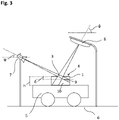
- figure 3 shows an arrangement of a robotic vehicle 5 and a stationary camera system, wherein the robotic vehicle 5 is set up to receive remote control data, in particular position data, and is movable on a surface 6 .
- the stationary camera system has at least one camera 7 and is arranged in a higher position than the robotic vehicle 5 and set up to detect the robotic vehicle 5 on the surface 6 and to transmit control data to the robotic vehicle 5 for the purpose of remote control.
- the robotic vehicle 5 has a position marker 1 which can be used to detect the position of the robotic vehicle 5 on the area 6 .
- the position marker 1 has a recess 3 with a diameter D, through which the camera 7 captures the interior of a cavity 10 below the effective area 4 of the marker. Depending on a detection angle ⁇ and a height h of the cavity 10, the camera 7 captures a lateral inner surface, a lower inner surface, or both a lateral and a lower inner surface of the cavity 10.
- the distance ⁇ between the inner surfaces of a cavity 10 located under the active marker surface 4 is designed as a function of the maximum detection angle ⁇ of the camera 7 and/or the angle of incidence ⁇ of a light source 8; the criterion for a minimum distance ⁇ between the inner surfaces and the active marker surface 4 is with h > tan( ⁇ ) * D is fulfilled.
- the absorption surface 9 is located just outside of an area located perpendicularly below the recess 3 .
- the detection direction of the camera 7 is directed opposite to an incidence direction of the light from the light source 8 .
Landscapes
- Physics & Mathematics (AREA)
- Engineering & Computer Science (AREA)
- General Physics & Mathematics (AREA)
- Aviation & Aerospace Engineering (AREA)
- Radar, Positioning & Navigation (AREA)
- Remote Sensing (AREA)
- Automation & Control Theory (AREA)
- Optics & Photonics (AREA)
- Electromagnetism (AREA)
- Control Of Position, Course, Altitude, Or Attitude Of Moving Bodies (AREA)
Claims (13)
- Marqueur de position (1) destiné à la détection optique par un capteur optique de prise d'images, en particulier une caméra (7), qui comprend une surface active de marqueur bidimensionnelle (4) ayant des parties de surface (2) dotées de propriétés optiques différentes, la surface active de marqueur (4) présentant une ou plusieurs parties de surface (2) réfléchissantes ou émettant de la lumière et une ou plusieurs parties de surface (2) sensiblement non réfléchissantes ou absorbant la lumière,
le marqueur de position (1) présente une extension tridimensionnelle et une partie de surface (2) est réalisée sous la forme d'un creux (3), caractérisé en ce que la surface active de marqueur (4) ferme une cavité (10) disposée sous ou derrière la surface active de marqueur (4), laquelle peut être vu à travers le creux (3). - Marqueur de position (1) selon la revendication 1, caractérisé en ce qu'une distance entre les surfaces intérieures de la cavité (10) et le creux (3) correspond au moins à la largeur du creux (3).
- Marqueur de position (1) selon la revendication 1 ou la revendication 2, caractérisé en ce qu'au moins une partie d'une surface intérieure de la cavité (10) visible à travers le creux (3) est conçue pour absorber la lumière.
- Marqueur de position (1) selon l'une des revendications 1 à 3, caractérisé en ce qu'une surface intérieure de la cavité (10) est utilisée comme(i) une surface noire, ou comme(ii) une surface textile, ou par(iii) des pyramides noires, des cônes ou des épines, en particulier jusqu'à une taille de 1-2 cm de longueur d'arête, ou une combinaison des caractéristiques (i), (ii) et (iii).
- Marqueur de position (1) selon l'une des revendications précédentes, caractérisé en ce que la surface active de marqueur (4) ferme une cavité (10) disposée sous ou derrière la surface active de marqueur (4), et la cavité (10) présente une ou plusieurs ouvertures inférieures.
- Marqueur de position (1) selon l'une des revendications précédentes, caractérisé en ce que la surface active de marqueur (4) présente une partie de surface éclairée (2') dans un creux (3).
- Marqueur de position (1) selon l'une des revendications précédentes, caractérisé en ce que la surface active de marqueur (4) présente une partie de surface éclairée (2') sous la forme d'une vitre en plexiglas, qui peut être éclairée latéralement ou par le dessous par une source lumineuse.
- Marqueur de position (1) selon l'une des revendications précédentes, caractérisé en ce que la surface active de marqueur (4) présente une partie de surface éclairée (2') dont la luminosité peut être réglée de manière adaptative au moyen d'un capteur de lumière.
- Marqueur de position (1) selon l'une des revendications précédentes, caractérisé en ce que la somme des parties de surface (2) réfléchissantes ou émettant de la lumière est réalisée plus petite que la somme des parties de surface (2) sensiblement non réfléchissantes ou absorbant la lumière.
- Véhicule robot (5), qui est mobile sur une surface (6), et qui est conçu pour recevoir des données de télécommande d'un système de caméras disposé de manière fixe avec au moins une caméra (7), caractérisé en ce que le véhicule robot (5) comporte un marqueur de position (1) selon l'une des revendications 1 à 9 pour assister une détection de position du véhicule robot (5) sur la surface (6).
- Agencement constitué d'un véhicule robot (5) qui est conçu pour recevoir des données de télécommande et qui est mobile sur une surface (6), et d'un système de caméras disposé de manière stationnaire avec au moins une caméra (7), la caméra (7) étant disposée à une position surélevée par rapport au véhicule robot (5) et étant conçue pour détecter le véhicule robot (5) sur la surface (6), et étant conçue pour détecter la position du véhicule robot (5) et pour communiquer au véhicule robot (5) des données de commande aux fins d'une télécommande,
caractérisé en ce que le véhicule robot (5) comprend un marqueur de position (1) selon l'une des revendications 1 à 9, à l'aide duquel une détection de position du véhicule robot (5) peut être obtenue sur la surface (6). - Agencement selon la revendication 11, caractérisé en ce que les distances entre les surfaces intérieures de la cavité (10) et le creux (3) sont dimensionnées en fonction de l'angle de détection maximal de la caméra (7) et/ou de l'angle d'incidence maximal d'une source lumineuse.
- Dispositif selon la revendication 11 ou la revendication 12, caractérisé en ce que la caméra (7) est positionnée de telle sorte qu'une direction de détection de la caméra (7) est opposée à une direction d'incidence de la lumière.
Applications Claiming Priority (2)
| Application Number | Priority Date | Filing Date | Title |
|---|---|---|---|
| DE102019108643 | 2019-04-02 | ||
| PCT/DE2020/100275 WO2020200369A1 (fr) | 2019-04-02 | 2020-04-02 | Véhicule robot avec marqueur de position ainsi que marqueur de position |
Publications (2)
| Publication Number | Publication Date |
|---|---|
| EP3948470A1 EP3948470A1 (fr) | 2022-02-09 |
| EP3948470B1 true EP3948470B1 (fr) | 2022-09-28 |
Family
ID=70475914
Family Applications (1)
| Application Number | Title | Priority Date | Filing Date |
|---|---|---|---|
| EP20722447.8A Active EP3948470B1 (fr) | 2019-04-02 | 2020-04-02 | Cible optique de positionnement, robot avec ladite cible et systeme de commande d'un tel robot |
Country Status (4)
| Country | Link |
|---|---|
| EP (1) | EP3948470B1 (fr) |
| DE (1) | DE102020109253A1 (fr) |
| DK (1) | DK3948470T3 (fr) |
| WO (1) | WO2020200369A1 (fr) |
Citations (1)
| Publication number | Priority date | Publication date | Assignee | Title |
|---|---|---|---|---|
| WO2010063916A1 (fr) * | 2008-12-04 | 2010-06-10 | Parrot | Jeu de drones munis de balises de reconnaissance |
Family Cites Families (5)
| Publication number | Priority date | Publication date | Assignee | Title |
|---|---|---|---|---|
| DE502005004417D1 (de) * | 2005-10-12 | 2008-07-24 | Brainlab Ag | Marker für ein Navigationssystem und Verfahren zum Detektieren eines Markers |
| US7643893B2 (en) * | 2006-07-24 | 2010-01-05 | The Boeing Company | Closed-loop feedback control using motion capture systems |
| EP2153168B1 (fr) * | 2007-05-21 | 2017-05-10 | Snap-on Incorporated | Procédé et appareil d'alignement de roues |
| DE102014000375A1 (de) | 2014-01-14 | 2015-07-16 | Grenzebach Maschinenbau Gmbh | Vorrichtung zur Orientierung für automatisch in Werkshallen geführte, elektrisch betriebene, Transportfahrzeuge |
| CN110520688A (zh) * | 2017-04-19 | 2019-11-29 | 恩普乐股份有限公司 | 标记单元 |
-
2020
- 2020-04-02 DK DK20722447.8T patent/DK3948470T3/da active
- 2020-04-02 WO PCT/DE2020/100275 patent/WO2020200369A1/fr not_active Ceased
- 2020-04-02 EP EP20722447.8A patent/EP3948470B1/fr active Active
- 2020-04-02 DE DE102020109253.9A patent/DE102020109253A1/de active Pending
Patent Citations (1)
| Publication number | Priority date | Publication date | Assignee | Title |
|---|---|---|---|---|
| WO2010063916A1 (fr) * | 2008-12-04 | 2010-06-10 | Parrot | Jeu de drones munis de balises de reconnaissance |
Also Published As
| Publication number | Publication date |
|---|---|
| WO2020200369A1 (fr) | 2020-10-08 |
| DK3948470T3 (da) | 2022-10-24 |
| DE102020109253A1 (de) | 2020-10-08 |
| EP3948470A1 (fr) | 2022-02-09 |
Similar Documents
| Publication | Publication Date | Title |
|---|---|---|
| DE102007045150B4 (de) | Scheinwerferanordnung für ein Fahrzeug und Verfahren zum Steuern einer Scheinwerferanordnung | |
| DE102018128948A1 (de) | Radarstrahl-formschirm für ein kraftfahrzeug | |
| EP2667218B1 (fr) | Capteur 3D à économie d'énergie | |
| WO2016071371A1 (fr) | Lampe chirurgicale et procédé pour faire fonctionner une lampe chirurgicale | |
| EP2306425B1 (fr) | Dispositif et procédé destinés à la détection d'axes de roue | |
| DE202011001702U1 (de) | Detektor und mobiler Automat mit demselben | |
| EP0388618A2 (fr) | Système de détermination de la position dans l'espace d'un objet à l'aide d'un capteur optique à vidéo | |
| DE19945588A1 (de) | Sensoranordnung | |
| EP3727933A1 (fr) | Véhicule à neige | |
| WO2015144405A1 (fr) | Dispositif d'éclairage commandé | |
| EP4251960A1 (fr) | Procédé et gonioradiomètre pour la mesure en fonction de la direction d'au moins une grandeur caractéristique d'éclairage ou de radiométrie d'une source de rayonnement optique installée dans un objet | |
| EP3438525B1 (fr) | Dispositif d'éclairage pour un dispositif de simulation d'un accident de véhicule | |
| DE102021206645B4 (de) | Mobiles Bodenreinigungsgerät sowie Verfahren zum Betreiben desselben | |
| WO2004061390A1 (fr) | Dispositif permettant de determiner la geometrie de roue et / ou d'essieu de vehicules a moteur | |
| DE102018214209A1 (de) | Augensicheres LIDAR-System mit einstellbarem Abtastbereich | |
| DE10340592B4 (de) | Kollisionsschutzeinrichtung für ein verstellbares Deckelement in einem Fahrzeug | |
| EP3948470A1 (fr) | Véhicule robot avec marqueur de position ainsi que marqueur de position | |
| EP2562128B1 (fr) | Industrial vehicle with optical lift height measurement system | |
| EP2327043B1 (fr) | Dispositif pour enregistrer des données biométriques | |
| DE102005011116A1 (de) | Vorrichtung zur Ansteuerung und/oder Überwachung eines Flügels | |
| DE19950060A1 (de) | Optoelektronische Sensoreinrichtung für ein Kraftfahrzeug | |
| DE202017005259U1 (de) | Einsatzfahrzeug mit Überkopfbeleuchtung | |
| WO2009112204A2 (fr) | Dispositif et procédé d'éclairage diffus d'une zone en forme de ligne | |
| EP3861373A1 (fr) | Dispositif et procédé de détermination d'une position d'un véhicule par rapport à un module de charge | |
| EP2584375B1 (fr) | Capteur de surveillance de porte et procédé de surveillance de la contre-arête de fermeture d'une porte, notamment d'une porte tournante |
Legal Events
| Date | Code | Title | Description |
|---|---|---|---|
| STAA | Information on the status of an ep patent application or granted ep patent |
Free format text: STATUS: UNKNOWN |
|
| STAA | Information on the status of an ep patent application or granted ep patent |
Free format text: STATUS: THE INTERNATIONAL PUBLICATION HAS BEEN MADE |
|
| PUAI | Public reference made under article 153(3) epc to a published international application that has entered the european phase |
Free format text: ORIGINAL CODE: 0009012 |
|
| STAA | Information on the status of an ep patent application or granted ep patent |
Free format text: STATUS: REQUEST FOR EXAMINATION WAS MADE |
|
| 17P | Request for examination filed |
Effective date: 20211029 |
|
| AK | Designated contracting states |
Kind code of ref document: A1 Designated state(s): AL AT BE BG CH CY CZ DE DK EE ES FI FR GB GR HR HU IE IS IT LI LT LU LV MC MK MT NL NO PL PT RO RS SE SI SK SM TR |
|
| REG | Reference to a national code |
Ref country code: DE Ref legal event code: R079 Ref document number: 502020001777 Country of ref document: DE Free format text: PREVIOUS MAIN CLASS: G05D0001020000 Ipc: G02B0027320000 |
|
| GRAP | Despatch of communication of intention to grant a patent |
Free format text: ORIGINAL CODE: EPIDOSNIGR1 |
|
| STAA | Information on the status of an ep patent application or granted ep patent |
Free format text: STATUS: GRANT OF PATENT IS INTENDED |
|
| RIC1 | Information provided on ipc code assigned before grant |
Ipc: G05D 1/02 20200101ALI20220405BHEP Ipc: G02B 5/00 20060101ALI20220405BHEP Ipc: G02B 27/32 20060101AFI20220405BHEP |
|
| DAV | Request for validation of the european patent (deleted) | ||
| DAX | Request for extension of the european patent (deleted) | ||
| INTG | Intention to grant announced |
Effective date: 20220510 |
|
| GRAS | Grant fee paid |
Free format text: ORIGINAL CODE: EPIDOSNIGR3 |
|
| GRAA | (expected) grant |
Free format text: ORIGINAL CODE: 0009210 |
|
| STAA | Information on the status of an ep patent application or granted ep patent |
Free format text: STATUS: THE PATENT HAS BEEN GRANTED |
|
| AK | Designated contracting states |
Kind code of ref document: B1 Designated state(s): AL AT BE BG CH CY CZ DE DK EE ES FI FR GB GR HR HU IE IS IT LI LT LU LV MC MK MT NL NO PL PT RO RS SE SI SK SM TR |
|
| REG | Reference to a national code |
Ref country code: GB Ref legal event code: FG4D Free format text: NOT ENGLISH |
|
| REG | Reference to a national code |
Ref country code: CH Ref legal event code: EP |
|
| REG | Reference to a national code |
Ref country code: AT Ref legal event code: REF Ref document number: 1521618 Country of ref document: AT Kind code of ref document: T Effective date: 20221015 |
|
| REG | Reference to a national code |
Ref country code: DE Ref legal event code: R096 Ref document number: 502020001777 Country of ref document: DE |
|
| REG | Reference to a national code |
Ref country code: DK Ref legal event code: T3 Effective date: 20221018 |
|
| REG | Reference to a national code |
Ref country code: IE Ref legal event code: FG4D Free format text: LANGUAGE OF EP DOCUMENT: GERMAN |
|
| REG | Reference to a national code |
Ref country code: SE Ref legal event code: TRGR |
|
| REG | Reference to a national code |
Ref country code: NL Ref legal event code: FP |
|
| REG | Reference to a national code |
Ref country code: LT Ref legal event code: MG9D |
|
| PG25 | Lapsed in a contracting state [announced via postgrant information from national office to epo] |
Ref country code: RS Free format text: LAPSE BECAUSE OF FAILURE TO SUBMIT A TRANSLATION OF THE DESCRIPTION OR TO PAY THE FEE WITHIN THE PRESCRIBED TIME-LIMIT Effective date: 20220928 Ref country code: NO Free format text: LAPSE BECAUSE OF FAILURE TO SUBMIT A TRANSLATION OF THE DESCRIPTION OR TO PAY THE FEE WITHIN THE PRESCRIBED TIME-LIMIT Effective date: 20221228 Ref country code: LV Free format text: LAPSE BECAUSE OF FAILURE TO SUBMIT A TRANSLATION OF THE DESCRIPTION OR TO PAY THE FEE WITHIN THE PRESCRIBED TIME-LIMIT Effective date: 20220928 Ref country code: LT Free format text: LAPSE BECAUSE OF FAILURE TO SUBMIT A TRANSLATION OF THE DESCRIPTION OR TO PAY THE FEE WITHIN THE PRESCRIBED TIME-LIMIT Effective date: 20220928 Ref country code: FI Free format text: LAPSE BECAUSE OF FAILURE TO SUBMIT A TRANSLATION OF THE DESCRIPTION OR TO PAY THE FEE WITHIN THE PRESCRIBED TIME-LIMIT Effective date: 20220928 |
|
| PG25 | Lapsed in a contracting state [announced via postgrant information from national office to epo] |
Ref country code: HR Free format text: LAPSE BECAUSE OF FAILURE TO SUBMIT A TRANSLATION OF THE DESCRIPTION OR TO PAY THE FEE WITHIN THE PRESCRIBED TIME-LIMIT Effective date: 20220928 Ref country code: GR Free format text: LAPSE BECAUSE OF FAILURE TO SUBMIT A TRANSLATION OF THE DESCRIPTION OR TO PAY THE FEE WITHIN THE PRESCRIBED TIME-LIMIT Effective date: 20221229 |
|
| PG25 | Lapsed in a contracting state [announced via postgrant information from national office to epo] |
Ref country code: SM Free format text: LAPSE BECAUSE OF FAILURE TO SUBMIT A TRANSLATION OF THE DESCRIPTION OR TO PAY THE FEE WITHIN THE PRESCRIBED TIME-LIMIT Effective date: 20220928 Ref country code: RO Free format text: LAPSE BECAUSE OF FAILURE TO SUBMIT A TRANSLATION OF THE DESCRIPTION OR TO PAY THE FEE WITHIN THE PRESCRIBED TIME-LIMIT Effective date: 20220928 Ref country code: PT Free format text: LAPSE BECAUSE OF FAILURE TO SUBMIT A TRANSLATION OF THE DESCRIPTION OR TO PAY THE FEE WITHIN THE PRESCRIBED TIME-LIMIT Effective date: 20230130 Ref country code: ES Free format text: LAPSE BECAUSE OF FAILURE TO SUBMIT A TRANSLATION OF THE DESCRIPTION OR TO PAY THE FEE WITHIN THE PRESCRIBED TIME-LIMIT Effective date: 20220928 Ref country code: CZ Free format text: LAPSE BECAUSE OF FAILURE TO SUBMIT A TRANSLATION OF THE DESCRIPTION OR TO PAY THE FEE WITHIN THE PRESCRIBED TIME-LIMIT Effective date: 20220928 |
|
| PG25 | Lapsed in a contracting state [announced via postgrant information from national office to epo] |
Ref country code: SK Free format text: LAPSE BECAUSE OF FAILURE TO SUBMIT A TRANSLATION OF THE DESCRIPTION OR TO PAY THE FEE WITHIN THE PRESCRIBED TIME-LIMIT Effective date: 20220928 Ref country code: PL Free format text: LAPSE BECAUSE OF FAILURE TO SUBMIT A TRANSLATION OF THE DESCRIPTION OR TO PAY THE FEE WITHIN THE PRESCRIBED TIME-LIMIT Effective date: 20220928 Ref country code: IS Free format text: LAPSE BECAUSE OF FAILURE TO SUBMIT A TRANSLATION OF THE DESCRIPTION OR TO PAY THE FEE WITHIN THE PRESCRIBED TIME-LIMIT Effective date: 20230128 Ref country code: EE Free format text: LAPSE BECAUSE OF FAILURE TO SUBMIT A TRANSLATION OF THE DESCRIPTION OR TO PAY THE FEE WITHIN THE PRESCRIBED TIME-LIMIT Effective date: 20220928 |
|
| REG | Reference to a national code |
Ref country code: DE Ref legal event code: R097 Ref document number: 502020001777 Country of ref document: DE |
|
| PG25 | Lapsed in a contracting state [announced via postgrant information from national office to epo] |
Ref country code: AL Free format text: LAPSE BECAUSE OF FAILURE TO SUBMIT A TRANSLATION OF THE DESCRIPTION OR TO PAY THE FEE WITHIN THE PRESCRIBED TIME-LIMIT Effective date: 20220928 |
|
| PLBE | No opposition filed within time limit |
Free format text: ORIGINAL CODE: 0009261 |
|
| STAA | Information on the status of an ep patent application or granted ep patent |
Free format text: STATUS: NO OPPOSITION FILED WITHIN TIME LIMIT |
|
| 26N | No opposition filed |
Effective date: 20230629 |
|
| PG25 | Lapsed in a contracting state [announced via postgrant information from national office to epo] |
Ref country code: SI Free format text: LAPSE BECAUSE OF FAILURE TO SUBMIT A TRANSLATION OF THE DESCRIPTION OR TO PAY THE FEE WITHIN THE PRESCRIBED TIME-LIMIT Effective date: 20220928 |
|
| PG25 | Lapsed in a contracting state [announced via postgrant information from national office to epo] |
Ref country code: MC Free format text: LAPSE BECAUSE OF FAILURE TO SUBMIT A TRANSLATION OF THE DESCRIPTION OR TO PAY THE FEE WITHIN THE PRESCRIBED TIME-LIMIT Effective date: 20220928 |
|
| PG25 | Lapsed in a contracting state [announced via postgrant information from national office to epo] |
Ref country code: MC Free format text: LAPSE BECAUSE OF FAILURE TO SUBMIT A TRANSLATION OF THE DESCRIPTION OR TO PAY THE FEE WITHIN THE PRESCRIBED TIME-LIMIT Effective date: 20220928 |
|
| REG | Reference to a national code |
Ref country code: IE Ref legal event code: MM4A |
|
| PG25 | Lapsed in a contracting state [announced via postgrant information from national office to epo] |
Ref country code: IE Free format text: LAPSE BECAUSE OF NON-PAYMENT OF DUE FEES Effective date: 20230402 |
|
| PG25 | Lapsed in a contracting state [announced via postgrant information from national office to epo] |
Ref country code: IE Free format text: LAPSE BECAUSE OF NON-PAYMENT OF DUE FEES Effective date: 20230402 |
|
| PG25 | Lapsed in a contracting state [announced via postgrant information from national office to epo] |
Ref country code: IT Free format text: LAPSE BECAUSE OF FAILURE TO SUBMIT A TRANSLATION OF THE DESCRIPTION OR TO PAY THE FEE WITHIN THE PRESCRIBED TIME-LIMIT Effective date: 20220928 |
|
| PG25 | Lapsed in a contracting state [announced via postgrant information from national office to epo] |
Ref country code: BG Free format text: LAPSE BECAUSE OF FAILURE TO SUBMIT A TRANSLATION OF THE DESCRIPTION OR TO PAY THE FEE WITHIN THE PRESCRIBED TIME-LIMIT Effective date: 20220928 |
|
| PG25 | Lapsed in a contracting state [announced via postgrant information from national office to epo] |
Ref country code: BG Free format text: LAPSE BECAUSE OF FAILURE TO SUBMIT A TRANSLATION OF THE DESCRIPTION OR TO PAY THE FEE WITHIN THE PRESCRIBED TIME-LIMIT Effective date: 20220928 |
|
| PG25 | Lapsed in a contracting state [announced via postgrant information from national office to epo] |
Ref country code: CY Free format text: LAPSE BECAUSE OF FAILURE TO SUBMIT A TRANSLATION OF THE DESCRIPTION OR TO PAY THE FEE WITHIN THE PRESCRIBED TIME-LIMIT; INVALID AB INITIO Effective date: 20200402 |
|
| PG25 | Lapsed in a contracting state [announced via postgrant information from national office to epo] |
Ref country code: HU Free format text: LAPSE BECAUSE OF FAILURE TO SUBMIT A TRANSLATION OF THE DESCRIPTION OR TO PAY THE FEE WITHIN THE PRESCRIBED TIME-LIMIT; INVALID AB INITIO Effective date: 20200402 |
|
| PG25 | Lapsed in a contracting state [announced via postgrant information from national office to epo] |
Ref country code: TR Free format text: LAPSE BECAUSE OF FAILURE TO SUBMIT A TRANSLATION OF THE DESCRIPTION OR TO PAY THE FEE WITHIN THE PRESCRIBED TIME-LIMIT Effective date: 20220928 |
|
| PGFP | Annual fee paid to national office [announced via postgrant information from national office to epo] |
Ref country code: GB Payment date: 20260325 Year of fee payment: 7 |
|
| REG | Reference to a national code |
Ref country code: CH Ref legal event code: U11 Free format text: ST27 STATUS EVENT CODE: U-0-0-U10-U11 (AS PROVIDED BY THE NATIONAL OFFICE) Effective date: 20260501 |
|
| PGFP | Annual fee paid to national office [announced via postgrant information from national office to epo] |
Ref country code: LU Payment date: 20260427 Year of fee payment: 7 Ref country code: NL Payment date: 20260427 Year of fee payment: 7 |
|
| PGFP | Annual fee paid to national office [announced via postgrant information from national office to epo] |
Ref country code: DK Payment date: 20260420 Year of fee payment: 7 |
|
| PGFP | Annual fee paid to national office [announced via postgrant information from national office to epo] |
Ref country code: DE Payment date: 20260430 Year of fee payment: 7 |
|
| PGFP | Annual fee paid to national office [announced via postgrant information from national office to epo] |
Ref country code: SE Payment date: 20260417 Year of fee payment: 7 Ref country code: AT Payment date: 20260427 Year of fee payment: 7 |
|
| PGFP | Annual fee paid to national office [announced via postgrant information from national office to epo] |
Ref country code: BE Payment date: 20260427 Year of fee payment: 7 Ref country code: CH Payment date: 20260501 Year of fee payment: 7 |
|
| PG25 | Lapsed in a contracting state [announced via postgrant information from national office to epo] |
Ref country code: MT Free format text: LAPSE BECAUSE OF NON-PAYMENT OF DUE FEES Effective date: 20230402 |
|
| PGFP | Annual fee paid to national office [announced via postgrant information from national office to epo] |
Ref country code: FR Payment date: 20260417 Year of fee payment: 7 |