EP3949879A1 - Laparoskopisches chirurgisches instrument - Google Patents
Laparoskopisches chirurgisches instrument Download PDFInfo
- Publication number
- EP3949879A1 EP3949879A1 EP20783074.6A EP20783074A EP3949879A1 EP 3949879 A1 EP3949879 A1 EP 3949879A1 EP 20783074 A EP20783074 A EP 20783074A EP 3949879 A1 EP3949879 A1 EP 3949879A1
- Authority
- EP
- European Patent Office
- Prior art keywords
- gripping
- push rods
- jaws
- hinged
- instrument according
- Prior art date
- Legal status (The legal status is an assumption and is not a legal conclusion. Google has not performed a legal analysis and makes no representation as to the accuracy of the status listed.)
- Granted
Links
Images

Classifications
-
- A—HUMAN NECESSITIES
- A61—MEDICAL OR VETERINARY SCIENCE; HYGIENE
- A61B—DIAGNOSIS; SURGERY; IDENTIFICATION
- A61B17/00—Surgical instruments, devices or methods
- A61B17/28—Surgical forceps
- A61B17/29—Forceps for use in minimally invasive surgery
- A61B17/2909—Handles
-
- A—HUMAN NECESSITIES
- A61—MEDICAL OR VETERINARY SCIENCE; HYGIENE
- A61B—DIAGNOSIS; SURGERY; IDENTIFICATION
- A61B17/00—Surgical instruments, devices or methods
- A61B17/28—Surgical forceps
- A61B17/29—Forceps for use in minimally invasive surgery
-
- A—HUMAN NECESSITIES
- A61—MEDICAL OR VETERINARY SCIENCE; HYGIENE
- A61B—DIAGNOSIS; SURGERY; IDENTIFICATION
- A61B18/00—Surgical instruments, devices or methods for transferring non-mechanical forms of energy to or from the body
- A61B18/04—Surgical instruments, devices or methods for transferring non-mechanical forms of energy to or from the body by heating
- A61B18/12—Surgical instruments, devices or methods for transferring non-mechanical forms of energy to or from the body by heating by passing a current through the tissue to be heated, e.g. high-frequency current
- A61B18/14—Probes or electrodes therefor
- A61B18/1442—Probes having pivoting end effectors, e.g. forceps
- A61B18/1445—Probes having pivoting end effectors, e.g. forceps at the distal end of a shaft, e.g. forceps or scissors at the end of a rigid rod
-
- A—HUMAN NECESSITIES
- A61—MEDICAL OR VETERINARY SCIENCE; HYGIENE
- A61B—DIAGNOSIS; SURGERY; IDENTIFICATION
- A61B17/00—Surgical instruments, devices or methods
- A61B17/28—Surgical forceps
- A61B17/29—Forceps for use in minimally invasive surgery
- A61B17/2909—Handles
- A61B2017/2912—Handles transmission of forces to actuating rod or piston
-
- A—HUMAN NECESSITIES
- A61—MEDICAL OR VETERINARY SCIENCE; HYGIENE
- A61B—DIAGNOSIS; SURGERY; IDENTIFICATION
- A61B17/00—Surgical instruments, devices or methods
- A61B17/28—Surgical forceps
- A61B17/29—Forceps for use in minimally invasive surgery
- A61B2017/2926—Details of heads or jaws
- A61B2017/2927—Details of heads or jaws the angular position of the head being adjustable with respect to the shaft
- A61B2017/2929—Details of heads or jaws the angular position of the head being adjustable with respect to the shaft with a head rotatable about the longitudinal axis of the shaft
-
- A—HUMAN NECESSITIES
- A61—MEDICAL OR VETERINARY SCIENCE; HYGIENE
- A61B—DIAGNOSIS; SURGERY; IDENTIFICATION
- A61B17/00—Surgical instruments, devices or methods
- A61B17/28—Surgical forceps
- A61B17/29—Forceps for use in minimally invasive surgery
- A61B2017/2926—Details of heads or jaws
- A61B2017/2932—Transmission of forces to jaw members
-
- A—HUMAN NECESSITIES
- A61—MEDICAL OR VETERINARY SCIENCE; HYGIENE
- A61B—DIAGNOSIS; SURGERY; IDENTIFICATION
- A61B17/00—Surgical instruments, devices or methods
- A61B17/28—Surgical forceps
- A61B17/29—Forceps for use in minimally invasive surgery
- A61B2017/2926—Details of heads or jaws
- A61B2017/2932—Transmission of forces to jaw members
- A61B2017/2933—Transmission of forces to jaw members camming or guiding means
- A61B2017/2936—Pins in guiding slots
Definitions
- the object of the present application is to provide of a laparoscopic surgical instrument.
- the invention proposes the development of a laparoscopic surgical instrument, which is provided with a manual gripping portion provided with three gripping members, one of them being fixed (non-movable) and the other two gripping members being movable and hinged such that each can perform an angular movement, facilitating the use of the tool during surgery.
- laparoscopic surgical apparatuses are known for surgery that requires the suturing and ligating of body tissues through incisions made in the walls of the body.
- the surgical tool acts in a single plane, thus limiting the degrees of freedom and consequently making it difficult for the surgeon to use.
- a laparoscopic instrument which is described in European patent EP-A-1 250 891 .
- This instrument stands out for comprising a pair of joining mechanisms capable of linking, on the one hand, a gripping member to a jaw member and a second gripping member linked to the second jaw member. Additionally, the two gripping members are capable of rotating with respect to a second plane thanks to the structural configuration of the two joining mechanisms.
- this instrument is relatively complex and the freedom of movement thereof is still limited as it does not allow a 360° rotation of the shaft that joins the jaw members with the gripping members, such that this instrument can be difficult to use during surgery.
- the present invention has been developed in order to provide a laparoscopic surgical instrument that is configured as a novelty within the field of application and solves the aforementioned drawbacks, further contributing other additional advantages that will be evident from the description that follows below.
- a laparoscopic surgical instrument comprising a manual gripping portion provided with two gripping members being movable and hinged such that each can perform an angular movement, configured to house a user's finger; a work tool (30) provided with two jaws being hinged with each other by a pivoting shaft, that can be handled by means of the gripping portion and; an actuator mechanism capable of transmitting movement from the gripping portion to the work tool, wherein the actuator mechanism comprises two push rods, wherein the distal end of each of the push rods is hingedly coupled to a corresponding jaw and the proximal end is rotatably attached to a corresponding annular body capable of longitudinal movement, such that the push rods are able to rotate, and wherein each gripping member is coupled to a respective annular body by means of connecting rods.
- the invention is characterised in that the gripping portion includes a third fixed gripping member configured to house a user's finger, being coupled to a support part wherein the two push rods are mounted, and located between the two hinged gripping members, the two gripping members being hinged to the third gripping member by means of a shaft.
- one of the movable gripping members is defined by a hook-shaped body, such that positioning and/or removal of the finger is facilitated during the use of the instrument.
- the instrument includes an arched contour extension that extends beyond the area provided for placement of a user's finger.
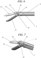
- it includes a guiding system to perform the angular movement of each of the jaws, the guiding system being provided with a groove in the shape of a slot present in each of the jaws, in which a protrusion protruding from each of the push rods is slidable.
- a greater opening angle is allowed which can be up to 110° and is constructively much simpler than other guiding systems known in the art.
- each of the jaws includes stop means that are provided to limit the angular movement thereof.
- the stop means are defined by a terminal area present on the jaw exhibiting two adjacent straight edges (35, 36) forming an obtuse angle with each other, and a straight area present on the facing jaw, provided to abut with one of the straight edges.
- the laparoscopic surgical instrument described thus represents an innovative structure with structural and constitutive features hitherto unknown for the purpose for which it is intended, reasons which, together with its practical utility, provide it with a sufficient basis to obtain the privilege of exclusivity that is requested.
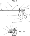
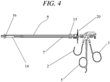
- a laparoscopic surgical instrument generally indicated with the reference (1), comprises a gripping portion provided with two movable gripping members (2,3) that are hinged to each other by means of a pivoting shaft (4), a work tool (30) provided with two jaws (31, 32) that are hinged to each other by means of a pivoting shaft (35) and an actuator mechanism capable of transmitting the movement from the gripping portion to the work tool (30), said actuator mechanism being described in greater detail below.
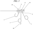
- the gripping portion includes a third fixed gripping member (5) configured to house a user's finger, being coupled to a support part (8) wherein the two push rods (6, 7) which are detailed below are mounted, and located between the two hinged gripping members, the two gripping members being hinged to the third gripping member by means of a shaft.
- One of the movable gripping members (3) and the fixed gripping member (5) exhibit an elongated shape with a rod section that ends with a section by way of a thimble, which have a very similar shape to conventional scissors thimbles, while the remaining movable gripping member (2) is defined by a hook-shaped body, such that the upper portion thereof is open (according to the orientation represented in the figures).
- the fixed gripping member (5) includes an extension with an arched contour (50) that extends beyond the area provided for the placement of a user's finger.
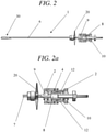
- the actuator mechanism capable of transmitting movement from the gripping portion to the work tool (30), wherein the actuator mechanism comprises two of the aforementioned push rods (6, 7), wherein the distal end of each of the push rods is hingedly coupled to a corresponding jaw and the proximal end is rotatably joined to a corresponding annular body capable of longitudinal movement, such that the push rods (6, 7) are capable of rotating, and wherein each gripping member is coupled to a respective annular body by means of connecting rods (11, 12).
- each gripping member (2, 3) is coupled to the two annular bodies (9, 10) by means of the set of two connecting rods (11, 12).
- Each of the connecting rods (11, 12) is coupled through one of the ends thereof to an open portion present in the lateral wall of the annular bodies (9, 10), such that they enable the annular body and consequently the push rod associated with the respective annular body to rotate.
- the open portion by way of a window through which the end of the connecting rod (11) can slide has been indicated with the numerical reference (90) in Figure 1a .
- a rotating wheel (20) that can be manually actuated enables the push rods (5, 6) to be rotated, the rotating wheel (20) being located in front of the gripping members (2, 3, 5) when the instrument (1) is in a position of use.
- the actuator mechanism may be protected by a casing (not shown for clarity purposes) made of any suitable material, such as a plastic material.
- a guiding system is provided to perform the angular movement of each of the jaws (31, 32), the guiding system being provided with a groove (33) that is open at one of the ends thereof in the form of a slot present in each of the jaws, in which a projection (34) protruding from the other push rod is slidable, as can be seen more clearly in Figures 5 to 7 .
- each of the jaws (31, 32) includes stop means to limit the angular movement thereof.
- stop means are defined by a terminal area present in the jaw exhibiting two adjacent straight edges (36, 37) forming an obtuse angle with each other, and a straight area present on the facing jaw, intended to abut with one of the straight edges.
- the instrument includes a tubular cover located around and along a large portion of the two push rods (6, 7).
- connection socket may be arranged, for example of the bipolar type, intended to be connected to a source of electrical current supply, such that electrical voltage can be transmitted if required.
- a cleaning system can be used comprising an internally hollow tubular member (14) that exhibits an open end with a sealing gasket (15) that adapts to the outer walls of the push rods (6, 7) while the opposite end exhibits an inlet socket (16) provided for coupling to a fluid supply equipment (not shown).
Landscapes
- Health & Medical Sciences (AREA)
- Surgery (AREA)
- Life Sciences & Earth Sciences (AREA)
- Biomedical Technology (AREA)
- Nuclear Medicine, Radiotherapy & Molecular Imaging (AREA)
- Engineering & Computer Science (AREA)
- Ophthalmology & Optometry (AREA)
- Heart & Thoracic Surgery (AREA)
- Medical Informatics (AREA)
- Molecular Biology (AREA)
- Animal Behavior & Ethology (AREA)
- General Health & Medical Sciences (AREA)
- Public Health (AREA)
- Veterinary Medicine (AREA)
- Surgical Instruments (AREA)
Applications Claiming Priority (2)
| Application Number | Priority Date | Filing Date | Title |
|---|---|---|---|
| ES201930528U ES1230155Y (es) | 2019-04-02 | 2019-04-02 | Instrumento quirúrgico laparoscópico |
| PCT/ES2020/070185 WO2020201596A1 (es) | 2019-04-02 | 2020-03-17 | Instrumento quirúrgico laparoscópico |
Publications (4)
| Publication Number | Publication Date |
|---|---|
| EP3949879A1 true EP3949879A1 (de) | 2022-02-09 |
| EP3949879A4 EP3949879A4 (de) | 2022-12-14 |
| EP3949879B1 EP3949879B1 (de) | 2023-12-27 |
| EP3949879C0 EP3949879C0 (de) | 2023-12-27 |
Family
ID=66615068
Family Applications (1)
| Application Number | Title | Priority Date | Filing Date |
|---|---|---|---|
| EP20783074.6A Active EP3949879B1 (de) | 2019-04-02 | 2020-03-17 | Laparoskopisches chirurgisches instrument |
Country Status (7)
| Country | Link |
|---|---|
| US (1) | US12193695B2 (de) |
| EP (1) | EP3949879B1 (de) |
| JP (1) | JP2022529406A (de) |
| CN (1) | CN113710172A (de) |
| BR (1) | BR112021019736A2 (de) |
| ES (2) | ES1230155Y (de) |
| WO (1) | WO2020201596A1 (de) |
Families Citing this family (2)
| Publication number | Priority date | Publication date | Assignee | Title |
|---|---|---|---|---|
| ES1230155Y (es) * | 2019-04-02 | 2019-08-19 | Servocad Microtronics S L | Instrumento quirúrgico laparoscópico |
| ES2988236B2 (es) | 2023-11-27 | 2025-06-10 | Servocad Microtronics S L | Cabezal para un instrumento quirúrgico laparoscópico |
Family Cites Families (33)
| Publication number | Priority date | Publication date | Assignee | Title |
|---|---|---|---|---|
| US5147373A (en) * | 1991-04-29 | 1992-09-15 | Ferzli George S | Laparoscopic instrument |
| US5383888A (en) | 1992-02-12 | 1995-01-24 | United States Surgical Corporation | Articulating endoscopic surgical apparatus |
| US5281220A (en) * | 1992-01-13 | 1994-01-25 | Blake Joseph W Iii | Endoscopic instrument |
| US5514157A (en) | 1992-02-12 | 1996-05-07 | United States Surgical Corporation | Articulating endoscopic surgical apparatus |
| US5261917A (en) * | 1992-02-19 | 1993-11-16 | Hasson Harrith M | Suture tying forceps with a plurality of suture holders and method of tying a suture |
| US5281235A (en) * | 1992-02-21 | 1994-01-25 | Habley Medical Technology Corporation | Needle manipulator |
| US5752973A (en) * | 1994-10-18 | 1998-05-19 | Archimedes Surgical, Inc. | Endoscopic surgical gripping instrument with universal joint jaw coupler |
| US6159224A (en) * | 1996-11-27 | 2000-12-12 | Yoon; Inbae | Multiple needle suturing instrument and method |
| NL1007751C2 (nl) * | 1997-12-09 | 1999-06-22 | Surgical Innovations Vof | Chirurgische inrichting. |
| US6159162A (en) * | 1998-05-04 | 2000-12-12 | Lsvp International, Inc. | Biopsy apparatus |
| DE19833600A1 (de) * | 1998-07-25 | 2000-03-02 | Storz Karl Gmbh & Co Kg | Medizinische Zange mit zwei unabhängig voneinander beweglichen Maulteilen |
| DE19926555A1 (de) * | 1999-06-11 | 2000-12-28 | Storz Karl Gmbh & Co Kg | Medizinisches Greifinstrument sowie Verfahren zur Verwendung dieses Greifinstruments |
| US6506208B2 (en) | 2000-03-06 | 2003-01-14 | Robert B. Hunt | Surgical instrument |
| US6358268B1 (en) | 2000-03-06 | 2002-03-19 | Robert B. Hunt | Surgical instrument |
| DE60218240T2 (de) | 2001-04-18 | 2007-11-22 | Olympus Corporation | Chirurgisches Instrument |
| US7758608B2 (en) * | 2002-07-25 | 2010-07-20 | Dicesare Paul | Enhanced dexterity surgical hand piece |
| JP2005066180A (ja) * | 2003-08-27 | 2005-03-17 | Olympus Corp | 医療用器具 |
| US20050075664A1 (en) | 2003-10-03 | 2005-04-07 | Olympus Corporation | Surgical instrument |
| DE102006028001B4 (de) * | 2006-06-14 | 2009-11-26 | Paul Peschke Gmbh | Chirurgische Greifzange |
| US8652120B2 (en) | 2007-01-10 | 2014-02-18 | Ethicon Endo-Surgery, Inc. | Surgical instrument with wireless communication between control unit and sensor transponders |
| ES2333509B2 (es) | 2009-10-07 | 2011-01-03 | Universidad De Cantabria | Instrumento para cirugia endoscopica. |
| US10172669B2 (en) * | 2009-10-09 | 2019-01-08 | Ethicon Llc | Surgical instrument comprising an energy trigger lockout |
| JP5940864B2 (ja) * | 2012-04-12 | 2016-06-29 | カール シュトルツ ゲゼルシャフト ミット ベシュレンクテル ハフツング ウント コンパニー コマンディートゲゼルシャフト | 医療用マニピュレータ |
| ES2385518B1 (es) | 2012-04-23 | 2013-05-31 | Servocad Microtronics, S.L. | Instrumento quirúrgico laparoscópico |
| ES1077793Y (es) | 2012-09-19 | 2013-01-10 | Servocad Microtronics S L | Herramienta mecanica |
| US9339285B2 (en) * | 2013-03-12 | 2016-05-17 | Levita Magnetics International Corp. | Grasper with magnetically-controlled positioning |
| US9844389B2 (en) * | 2014-10-10 | 2017-12-19 | Scholten Surgical Instruments, Inc. | Push-to-close actuated dual action spaced pivot assembly for surgical instrument jaws, blades, and forceps |
| US10398459B2 (en) * | 2015-04-02 | 2019-09-03 | Aod Holdings Llc | Combination device for endoscopic and arthroscopic surgical procedures |
| US10987120B2 (en) * | 2017-01-10 | 2021-04-27 | New Wave Endo-Surgery Inc. | Multifunction surgical instrument for use in laparoscopic surgery |
| US11950871B2 (en) * | 2018-01-16 | 2024-04-09 | Multi Scopic Instruments, Llc | End effector |
| US11696761B2 (en) * | 2019-03-25 | 2023-07-11 | Cilag Gmbh International | Firing drive arrangements for surgical systems |
| ES1230155Y (es) * | 2019-04-02 | 2019-08-19 | Servocad Microtronics S L | Instrumento quirúrgico laparoscópico |
| US11737844B2 (en) * | 2020-08-19 | 2023-08-29 | Covidien Lp | End effector assembly for use in a robotic surgical instrument |
-
2019
- 2019-04-02 ES ES201930528U patent/ES1230155Y/es active Active
-
2020
- 2020-03-17 EP EP20783074.6A patent/EP3949879B1/de active Active
- 2020-03-17 US US17/600,602 patent/US12193695B2/en active Active
- 2020-03-17 BR BR112021019736A patent/BR112021019736A2/pt not_active Application Discontinuation
- 2020-03-17 CN CN202080026627.8A patent/CN113710172A/zh active Pending
- 2020-03-17 WO PCT/ES2020/070185 patent/WO2020201596A1/es not_active Ceased
- 2020-03-17 JP JP2021553774A patent/JP2022529406A/ja active Pending
- 2020-03-17 ES ES20783074T patent/ES2969752T3/es active Active
Also Published As
| Publication number | Publication date |
|---|---|
| CN113710172A (zh) | 2021-11-26 |
| EP3949879B1 (de) | 2023-12-27 |
| JP2022529406A (ja) | 2022-06-22 |
| ES2969752T3 (es) | 2024-05-22 |
| ES1230155U (es) | 2019-05-28 |
| US12193695B2 (en) | 2025-01-14 |
| WO2020201596A1 (es) | 2020-10-08 |
| US20220192691A1 (en) | 2022-06-23 |
| EP3949879A4 (de) | 2022-12-14 |
| ES1230155Y (es) | 2019-08-19 |
| EP3949879C0 (de) | 2023-12-27 |
| BR112021019736A2 (pt) | 2021-12-07 |
Similar Documents
| Publication | Publication Date | Title |
|---|---|---|
| US11337588B2 (en) | Endoscope | |
| US10624531B2 (en) | Endoscope | |
| US10624617B2 (en) | Endoscope | |
| US6077290A (en) | Endoscopic instrument with removable front end | |
| JP4938156B2 (ja) | 手術用鉗子 | |
| CA2680258C (en) | Improved end effector mechanism for a surgical instrument | |
| US6508827B1 (en) | Instrument for application in endoscopic surgery | |
| US6533797B1 (en) | Control grip assembly | |
| EP2842503B1 (de) | Laparoskopisches chirurgisches instrument | |
| KR20180133535A (ko) | 복강경에서 사용하기 위한 조합형 가위-그래스퍼 도구 | |
| CN115005931B (zh) | 微创手术器械组件及微创手术器械 | |
| EP3949879B1 (de) | Laparoskopisches chirurgisches instrument | |
| CN113573852A (zh) | 手术器具和医疗操纵器系统 | |
| CN111568553B (zh) | 一种快速更换的微创机器人末端手术器械 | |
| GB2421912A (en) | Laparoscopic forceps | |
| US7488296B1 (en) | Multifunctional actuator rod and handle for pushing a driver cable of a biopsy grasping instrument | |
| CN121359873B (zh) | 镜钳复合器械 | |
| CN223489823U (zh) | 手术执行器、手术工具及手术机器人 | |
| CN213310120U (zh) | 一种用于腔镜手术的圆杆钳 | |
| GB2374017A (en) | Endoscopic or laparoscopic grasping and cutting device | |
| CN121359873A (zh) | 镜钳复合器械 | |
| EP3302316B1 (de) | Endoskop | |
| US20170056095A1 (en) | Work Device For A Microsurgical Instrument, Microsurgical Instrument, And Power And Torque Transmission Hose |
Legal Events
| Date | Code | Title | Description |
|---|---|---|---|
| STAA | Information on the status of an ep patent application or granted ep patent |
Free format text: STATUS: THE INTERNATIONAL PUBLICATION HAS BEEN MADE |
|
| PUAI | Public reference made under article 153(3) epc to a published international application that has entered the european phase |
Free format text: ORIGINAL CODE: 0009012 |
|
| STAA | Information on the status of an ep patent application or granted ep patent |
Free format text: STATUS: REQUEST FOR EXAMINATION WAS MADE |
|
| 17P | Request for examination filed |
Effective date: 20210922 |
|
| AK | Designated contracting states |
Kind code of ref document: A1 Designated state(s): AL AT BE BG CH CY CZ DE DK EE ES FI FR GB GR HR HU IE IS IT LI LT LU LV MC MK MT NL NO PL PT RO RS SE SI SK SM TR |
|
| DAV | Request for validation of the european patent (deleted) | ||
| DAX | Request for extension of the european patent (deleted) | ||
| A4 | Supplementary search report drawn up and despatched |
Effective date: 20221115 |
|
| RIC1 | Information provided on ipc code assigned before grant |
Ipc: A61B 17/29 20060101AFI20221109BHEP |
|
| GRAP | Despatch of communication of intention to grant a patent |
Free format text: ORIGINAL CODE: EPIDOSNIGR1 |
|
| STAA | Information on the status of an ep patent application or granted ep patent |
Free format text: STATUS: GRANT OF PATENT IS INTENDED |
|
| INTG | Intention to grant announced |
Effective date: 20231020 |
|
| RAP3 | Party data changed (applicant data changed or rights of an application transferred) |
Owner name: SERVOCAD MICROTRONICS S.L. |
|
| GRAS | Grant fee paid |
Free format text: ORIGINAL CODE: EPIDOSNIGR3 |
|
| GRAA | (expected) grant |
Free format text: ORIGINAL CODE: 0009210 |
|
| STAA | Information on the status of an ep patent application or granted ep patent |
Free format text: STATUS: THE PATENT HAS BEEN GRANTED |
|
| AK | Designated contracting states |
Kind code of ref document: B1 Designated state(s): AL AT BE BG CH CY CZ DE DK EE ES FI FR GB GR HR HU IE IS IT LI LT LU LV MC MK MT NL NO PL PT RO RS SE SI SK SM TR |
|
| REG | Reference to a national code |
Ref country code: GB Ref legal event code: FG4D |
|
| REG | Reference to a national code |
Ref country code: CH Ref legal event code: EP |
|
| REG | Reference to a national code |
Ref country code: DE Ref legal event code: R096 Ref document number: 602020023485 Country of ref document: DE |
|
| REG | Reference to a national code |
Ref country code: IE Ref legal event code: FG4D |
|
| U01 | Request for unitary effect filed |
Effective date: 20240112 |
|
| U07 | Unitary effect registered |
Designated state(s): AT BE BG DE DK EE FI FR IT LT LU LV MT NL PT SE SI Effective date: 20240124 |
|
| U20 | Renewal fee for the european patent with unitary effect paid |
Year of fee payment: 5 Effective date: 20240125 |
|
| PG25 | Lapsed in a contracting state [announced via postgrant information from national office to epo] |
Ref country code: GR Free format text: LAPSE BECAUSE OF FAILURE TO SUBMIT A TRANSLATION OF THE DESCRIPTION OR TO PAY THE FEE WITHIN THE PRESCRIBED TIME-LIMIT Effective date: 20240328 |
|
| PG25 | Lapsed in a contracting state [announced via postgrant information from national office to epo] |
Ref country code: GR Free format text: LAPSE BECAUSE OF FAILURE TO SUBMIT A TRANSLATION OF THE DESCRIPTION OR TO PAY THE FEE WITHIN THE PRESCRIBED TIME-LIMIT Effective date: 20240328 |
|
| REG | Reference to a national code |
Ref country code: ES Ref legal event code: FG2A Ref document number: 2969752 Country of ref document: ES Kind code of ref document: T3 Effective date: 20240522 |
|
| PG25 | Lapsed in a contracting state [announced via postgrant information from national office to epo] |
Ref country code: RS Free format text: LAPSE BECAUSE OF FAILURE TO SUBMIT A TRANSLATION OF THE DESCRIPTION OR TO PAY THE FEE WITHIN THE PRESCRIBED TIME-LIMIT Effective date: 20231227 Ref country code: NO Free format text: LAPSE BECAUSE OF FAILURE TO SUBMIT A TRANSLATION OF THE DESCRIPTION OR TO PAY THE FEE WITHIN THE PRESCRIBED TIME-LIMIT Effective date: 20240327 Ref country code: HR Free format text: LAPSE BECAUSE OF FAILURE TO SUBMIT A TRANSLATION OF THE DESCRIPTION OR TO PAY THE FEE WITHIN THE PRESCRIBED TIME-LIMIT Effective date: 20231227 |
|
| PG25 | Lapsed in a contracting state [announced via postgrant information from national office to epo] |
Ref country code: IS Free format text: LAPSE BECAUSE OF FAILURE TO SUBMIT A TRANSLATION OF THE DESCRIPTION OR TO PAY THE FEE WITHIN THE PRESCRIBED TIME-LIMIT Effective date: 20240427 |
|
| PG25 | Lapsed in a contracting state [announced via postgrant information from national office to epo] |
Ref country code: CZ Free format text: LAPSE BECAUSE OF FAILURE TO SUBMIT A TRANSLATION OF THE DESCRIPTION OR TO PAY THE FEE WITHIN THE PRESCRIBED TIME-LIMIT Effective date: 20231227 |
|
| PG25 | Lapsed in a contracting state [announced via postgrant information from national office to epo] |
Ref country code: SK Free format text: LAPSE BECAUSE OF FAILURE TO SUBMIT A TRANSLATION OF THE DESCRIPTION OR TO PAY THE FEE WITHIN THE PRESCRIBED TIME-LIMIT Effective date: 20231227 |
|
| PG25 | Lapsed in a contracting state [announced via postgrant information from national office to epo] |
Ref country code: SM Free format text: LAPSE BECAUSE OF FAILURE TO SUBMIT A TRANSLATION OF THE DESCRIPTION OR TO PAY THE FEE WITHIN THE PRESCRIBED TIME-LIMIT Effective date: 20231227 Ref country code: SK Free format text: LAPSE BECAUSE OF FAILURE TO SUBMIT A TRANSLATION OF THE DESCRIPTION OR TO PAY THE FEE WITHIN THE PRESCRIBED TIME-LIMIT Effective date: 20231227 Ref country code: RO Free format text: LAPSE BECAUSE OF FAILURE TO SUBMIT A TRANSLATION OF THE DESCRIPTION OR TO PAY THE FEE WITHIN THE PRESCRIBED TIME-LIMIT Effective date: 20231227 Ref country code: IS Free format text: LAPSE BECAUSE OF FAILURE TO SUBMIT A TRANSLATION OF THE DESCRIPTION OR TO PAY THE FEE WITHIN THE PRESCRIBED TIME-LIMIT Effective date: 20240427 Ref country code: CZ Free format text: LAPSE BECAUSE OF FAILURE TO SUBMIT A TRANSLATION OF THE DESCRIPTION OR TO PAY THE FEE WITHIN THE PRESCRIBED TIME-LIMIT Effective date: 20231227 |
|
| PG25 | Lapsed in a contracting state [announced via postgrant information from national office to epo] |
Ref country code: PL Free format text: LAPSE BECAUSE OF FAILURE TO SUBMIT A TRANSLATION OF THE DESCRIPTION OR TO PAY THE FEE WITHIN THE PRESCRIBED TIME-LIMIT Effective date: 20231227 |
|
| PG25 | Lapsed in a contracting state [announced via postgrant information from national office to epo] |
Ref country code: PL Free format text: LAPSE BECAUSE OF FAILURE TO SUBMIT A TRANSLATION OF THE DESCRIPTION OR TO PAY THE FEE WITHIN THE PRESCRIBED TIME-LIMIT Effective date: 20231227 |
|
| REG | Reference to a national code |
Ref country code: DE Ref legal event code: R097 Ref document number: 602020023485 Country of ref document: DE |
|
| REG | Reference to a national code |
Ref country code: CH Ref legal event code: PL |
|
| PLBE | No opposition filed within time limit |
Free format text: ORIGINAL CODE: 0009261 |
|
| STAA | Information on the status of an ep patent application or granted ep patent |
Free format text: STATUS: NO OPPOSITION FILED WITHIN TIME LIMIT |
|
| PG25 | Lapsed in a contracting state [announced via postgrant information from national office to epo] |
Ref country code: MC Free format text: LAPSE BECAUSE OF FAILURE TO SUBMIT A TRANSLATION OF THE DESCRIPTION OR TO PAY THE FEE WITHIN THE PRESCRIBED TIME-LIMIT Effective date: 20231227 |
|
| PG25 | Lapsed in a contracting state [announced via postgrant information from national office to epo] |
Ref country code: MC Free format text: LAPSE BECAUSE OF FAILURE TO SUBMIT A TRANSLATION OF THE DESCRIPTION OR TO PAY THE FEE WITHIN THE PRESCRIBED TIME-LIMIT Effective date: 20231227 |
|
| 26N | No opposition filed |
Effective date: 20240930 |
|
| PG25 | Lapsed in a contracting state [announced via postgrant information from national office to epo] |
Ref country code: IE Free format text: LAPSE BECAUSE OF NON-PAYMENT OF DUE FEES Effective date: 20240317 |
|
| PG25 | Lapsed in a contracting state [announced via postgrant information from national office to epo] |
Ref country code: IE Free format text: LAPSE BECAUSE OF NON-PAYMENT OF DUE FEES Effective date: 20240317 Ref country code: CH Free format text: LAPSE BECAUSE OF NON-PAYMENT OF DUE FEES Effective date: 20240331 |
|
| U20 | Renewal fee for the european patent with unitary effect paid |
Year of fee payment: 6 Effective date: 20250226 |
|
| PGFP | Annual fee paid to national office [announced via postgrant information from national office to epo] |
Ref country code: ES Payment date: 20250514 Year of fee payment: 6 |
|
| PG25 | Lapsed in a contracting state [announced via postgrant information from national office to epo] |
Ref country code: CY Free format text: LAPSE BECAUSE OF FAILURE TO SUBMIT A TRANSLATION OF THE DESCRIPTION OR TO PAY THE FEE WITHIN THE PRESCRIBED TIME-LIMIT; INVALID AB INITIO Effective date: 20200317 |
|
| PG25 | Lapsed in a contracting state [announced via postgrant information from national office to epo] |
Ref country code: HU Free format text: LAPSE BECAUSE OF FAILURE TO SUBMIT A TRANSLATION OF THE DESCRIPTION OR TO PAY THE FEE WITHIN THE PRESCRIBED TIME-LIMIT; INVALID AB INITIO Effective date: 20200317 |
|
| PG25 | Lapsed in a contracting state [announced via postgrant information from national office to epo] |
Ref country code: TR Free format text: LAPSE BECAUSE OF FAILURE TO SUBMIT A TRANSLATION OF THE DESCRIPTION OR TO PAY THE FEE WITHIN THE PRESCRIBED TIME-LIMIT Effective date: 20231227 |
|
| U20 | Renewal fee for the european patent with unitary effect paid |
Year of fee payment: 7 Effective date: 20260305 |
|
| PGFP | Annual fee paid to national office [announced via postgrant information from national office to epo] |
Ref country code: GB Payment date: 20260311 Year of fee payment: 7 |