EP3950403A1 - Dispositif d'entraînement pour machine synchrone à aimants permanents, procédé de compensation de couple pour machine synchrone à aimants permanents et véhicule électrique - Google Patents
Dispositif d'entraînement pour machine synchrone à aimants permanents, procédé de compensation de couple pour machine synchrone à aimants permanents et véhicule électrique Download PDFInfo
- Publication number
- EP3950403A1 EP3950403A1 EP19922242.3A EP19922242A EP3950403A1 EP 3950403 A1 EP3950403 A1 EP 3950403A1 EP 19922242 A EP19922242 A EP 19922242A EP 3950403 A1 EP3950403 A1 EP 3950403A1
- Authority
- EP
- European Patent Office
- Prior art keywords
- permanent
- torque
- synchronous machine
- magnet synchronous
- calculation unit
- Prior art date
- Legal status (The legal status is an assumption and is not a legal conclusion. Google has not performed a legal analysis and makes no representation as to the accuracy of the status listed.)
- Pending
Links
- 230000001360 synchronised effect Effects 0.000 title claims abstract description 249
- 238000000034 method Methods 0.000 title claims description 16
- 238000004364 calculation method Methods 0.000 claims abstract description 381
- 238000012937 correction Methods 0.000 claims abstract description 225
- 230000004907 flux Effects 0.000 claims abstract description 126
- 238000001514 detection method Methods 0.000 claims description 70
- XEEYBQQBJWHFJM-UHFFFAOYSA-N Iron Chemical compound [Fe] XEEYBQQBJWHFJM-UHFFFAOYSA-N 0.000 description 74
- 238000010586 diagram Methods 0.000 description 72
- 230000008859 change Effects 0.000 description 57
- 229910052742 iron Inorganic materials 0.000 description 37
- 238000010606 normalization Methods 0.000 description 23
- 238000005259 measurement Methods 0.000 description 18
- 238000006243 chemical reaction Methods 0.000 description 17
- 239000003990 capacitor Substances 0.000 description 14
- 238000009499 grossing Methods 0.000 description 14
- 230000001419 dependent effect Effects 0.000 description 9
- 230000006870 function Effects 0.000 description 8
- 238000012360 testing method Methods 0.000 description 8
- 230000004044 response Effects 0.000 description 7
- 230000005347 demagnetization Effects 0.000 description 5
- 238000013461 design Methods 0.000 description 5
- 238000004804 winding Methods 0.000 description 5
- 239000000463 material Substances 0.000 description 4
- 238000012545 processing Methods 0.000 description 2
- 230000009467 reduction Effects 0.000 description 2
- 238000004088 simulation Methods 0.000 description 2
- RYGMFSIKBFXOCR-UHFFFAOYSA-N Copper Chemical compound [Cu] RYGMFSIKBFXOCR-UHFFFAOYSA-N 0.000 description 1
- 229910052802 copper Inorganic materials 0.000 description 1
- 239000010949 copper Substances 0.000 description 1
- 230000006866 deterioration Effects 0.000 description 1
- 230000000694 effects Effects 0.000 description 1
- 239000010687 lubricating oil Substances 0.000 description 1
- 238000010248 power generation Methods 0.000 description 1
- 230000008569 process Effects 0.000 description 1
Images


Classifications
-
- H—ELECTRICITY
- H02—GENERATION; CONVERSION OR DISTRIBUTION OF ELECTRIC POWER
- H02M—APPARATUS FOR CONVERSION BETWEEN AC AND AC, BETWEEN AC AND DC, OR BETWEEN DC AND DC, AND FOR USE WITH MAINS OR SIMILAR POWER SUPPLY SYSTEMS; CONVERSION OF DC OR AC INPUT POWER INTO SURGE OUTPUT POWER; CONTROL OR REGULATION THEREOF
- H02M7/00—Conversion of AC power input into DC power output; Conversion of DC power input into AC power output
- H02M7/42—Conversion of DC power input into AC power output without possibility of reversal
- H02M7/44—Conversion of DC power input into AC power output without possibility of reversal by static converters
- H02M7/48—Conversion of DC power input into AC power output without possibility of reversal by static converters using discharge tubes with control electrode or semiconductor devices with control electrode
- H02M7/53—Conversion of DC power input into AC power output without possibility of reversal by static converters using discharge tubes with control electrode or semiconductor devices with control electrode using devices of a triode or transistor type requiring continuous application of a control signal
- H02M7/537—Conversion of DC power input into AC power output without possibility of reversal by static converters using discharge tubes with control electrode or semiconductor devices with control electrode using devices of a triode or transistor type requiring continuous application of a control signal using semiconductor devices only, e.g. single switched pulse inverters
- H02M7/539—Conversion of DC power input into AC power output without possibility of reversal by static converters using discharge tubes with control electrode or semiconductor devices with control electrode using devices of a triode or transistor type requiring continuous application of a control signal using semiconductor devices only, e.g. single switched pulse inverters with automatic control of output wave form or frequency
- H02M7/5395—Conversion of DC power input into AC power output without possibility of reversal by static converters using discharge tubes with control electrode or semiconductor devices with control electrode using devices of a triode or transistor type requiring continuous application of a control signal using semiconductor devices only, e.g. single switched pulse inverters with automatic control of output wave form or frequency by pulse-width modulation
-
- B—PERFORMING OPERATIONS; TRANSPORTING
- B60—VEHICLES IN GENERAL
- B60L—PROPULSION OF ELECTRICALLY-PROPELLED VEHICLES; SUPPLYING ELECTRIC POWER FOR AUXILIARY EQUIPMENT OF ELECTRICALLY-PROPELLED VEHICLES; ELECTRODYNAMIC BRAKE SYSTEMS FOR VEHICLES IN GENERAL; MAGNETIC SUSPENSION OR LEVITATION FOR VEHICLES; MONITORING OPERATING VARIABLES OF ELECTRICALLY-PROPELLED VEHICLES; ELECTRIC SAFETY DEVICES FOR ELECTRICALLY-PROPELLED VEHICLES
- B60L15/00—Methods, circuits, or devices for controlling the traction-motor speed of electrically-propelled vehicles
- B60L15/007—Physical arrangements or structures of drive train converters specially adapted for the propulsion motors of electric vehicles
-
- B—PERFORMING OPERATIONS; TRANSPORTING
- B60—VEHICLES IN GENERAL
- B60L—PROPULSION OF ELECTRICALLY-PROPELLED VEHICLES; SUPPLYING ELECTRIC POWER FOR AUXILIARY EQUIPMENT OF ELECTRICALLY-PROPELLED VEHICLES; ELECTRODYNAMIC BRAKE SYSTEMS FOR VEHICLES IN GENERAL; MAGNETIC SUSPENSION OR LEVITATION FOR VEHICLES; MONITORING OPERATING VARIABLES OF ELECTRICALLY-PROPELLED VEHICLES; ELECTRIC SAFETY DEVICES FOR ELECTRICALLY-PROPELLED VEHICLES
- B60L15/00—Methods, circuits, or devices for controlling the traction-motor speed of electrically-propelled vehicles
- B60L15/02—Methods, circuits, or devices for controlling the traction-motor speed of electrically-propelled vehicles characterised by the form of the current used in the control circuit
- B60L15/025—Methods, circuits, or devices for controlling the traction-motor speed of electrically-propelled vehicles characterised by the form of the current used in the control circuit using field orientation; Vector control; Direct Torque Control [DTC]
-
- B—PERFORMING OPERATIONS; TRANSPORTING
- B60—VEHICLES IN GENERAL
- B60L—PROPULSION OF ELECTRICALLY-PROPELLED VEHICLES; SUPPLYING ELECTRIC POWER FOR AUXILIARY EQUIPMENT OF ELECTRICALLY-PROPELLED VEHICLES; ELECTRODYNAMIC BRAKE SYSTEMS FOR VEHICLES IN GENERAL; MAGNETIC SUSPENSION OR LEVITATION FOR VEHICLES; MONITORING OPERATING VARIABLES OF ELECTRICALLY-PROPELLED VEHICLES; ELECTRIC SAFETY DEVICES FOR ELECTRICALLY-PROPELLED VEHICLES
- B60L50/00—Electric propulsion with power supplied within the vehicle
- B60L50/50—Electric propulsion with power supplied within the vehicle using propulsion power supplied by batteries or fuel cells
- B60L50/51—Electric propulsion with power supplied within the vehicle using propulsion power supplied by batteries or fuel cells characterised by AC-motors
-
- H—ELECTRICITY
- H02—GENERATION; CONVERSION OR DISTRIBUTION OF ELECTRIC POWER
- H02P—CONTROL OR REGULATION OF ELECTRIC MOTORS, ELECTRIC GENERATORS OR DYNAMO-ELECTRIC CONVERTERS; CONTROLLING TRANSFORMERS, REACTORS OR CHOKE COILS
- H02P21/00—Arrangements or methods for the control of electric machines by vector control, e.g. by control of field orientation
- H02P21/0085—Arrangements or methods for the control of electric machines by vector control, e.g. by control of field orientation specially adapted for high speeds, e.g. above nominal speed
- H02P21/0089—Arrangements or methods for the control of electric machines by vector control, e.g. by control of field orientation specially adapted for high speeds, e.g. above nominal speed using field weakening
-
- H—ELECTRICITY
- H02—GENERATION; CONVERSION OR DISTRIBUTION OF ELECTRIC POWER
- H02P—CONTROL OR REGULATION OF ELECTRIC MOTORS, ELECTRIC GENERATORS OR DYNAMO-ELECTRIC CONVERTERS; CONTROLLING TRANSFORMERS, REACTORS OR CHOKE COILS
- H02P21/00—Arrangements or methods for the control of electric machines by vector control, e.g. by control of field orientation
- H02P21/22—Current control, e.g. using a current control loop
-
- H—ELECTRICITY
- H02—GENERATION; CONVERSION OR DISTRIBUTION OF ELECTRIC POWER
- H02P—CONTROL OR REGULATION OF ELECTRIC MOTORS, ELECTRIC GENERATORS OR DYNAMO-ELECTRIC CONVERTERS; CONTROLLING TRANSFORMERS, REACTORS OR CHOKE COILS
- H02P29/00—Arrangements for regulating or controlling electric motors, appropriate for both AC and DC motors
- H02P29/60—Controlling or determining the temperature of the motor or of the drive
- H02P29/66—Controlling or determining the temperature of the rotor
- H02P29/662—Controlling or determining the temperature of the rotor the rotor having permanent magnets
-
- H—ELECTRICITY
- H02—GENERATION; CONVERSION OR DISTRIBUTION OF ELECTRIC POWER
- H02P—CONTROL OR REGULATION OF ELECTRIC MOTORS, ELECTRIC GENERATORS OR DYNAMO-ELECTRIC CONVERTERS; CONTROLLING TRANSFORMERS, REACTORS OR CHOKE COILS
- H02P6/00—Arrangements for controlling synchronous motors or other dynamo-electric motors using electronic commutation dependent on the rotor position; Electronic commutators therefor
- H02P6/14—Electronic commutators
- H02P6/16—Circuit arrangements for detecting position
-
- B—PERFORMING OPERATIONS; TRANSPORTING
- B60—VEHICLES IN GENERAL
- B60L—PROPULSION OF ELECTRICALLY-PROPELLED VEHICLES; SUPPLYING ELECTRIC POWER FOR AUXILIARY EQUIPMENT OF ELECTRICALLY-PROPELLED VEHICLES; ELECTRODYNAMIC BRAKE SYSTEMS FOR VEHICLES IN GENERAL; MAGNETIC SUSPENSION OR LEVITATION FOR VEHICLES; MONITORING OPERATING VARIABLES OF ELECTRICALLY-PROPELLED VEHICLES; ELECTRIC SAFETY DEVICES FOR ELECTRICALLY-PROPELLED VEHICLES
- B60L2200/00—Type of vehicles
- B60L2200/26—Rail vehicles
-
- B—PERFORMING OPERATIONS; TRANSPORTING
- B60—VEHICLES IN GENERAL
- B60L—PROPULSION OF ELECTRICALLY-PROPELLED VEHICLES; SUPPLYING ELECTRIC POWER FOR AUXILIARY EQUIPMENT OF ELECTRICALLY-PROPELLED VEHICLES; ELECTRODYNAMIC BRAKE SYSTEMS FOR VEHICLES IN GENERAL; MAGNETIC SUSPENSION OR LEVITATION FOR VEHICLES; MONITORING OPERATING VARIABLES OF ELECTRICALLY-PROPELLED VEHICLES; ELECTRIC SAFETY DEVICES FOR ELECTRICALLY-PROPELLED VEHICLES
- B60L2210/00—Converter types
- B60L2210/20—AC to AC converters
-
- B—PERFORMING OPERATIONS; TRANSPORTING
- B60—VEHICLES IN GENERAL
- B60L—PROPULSION OF ELECTRICALLY-PROPELLED VEHICLES; SUPPLYING ELECTRIC POWER FOR AUXILIARY EQUIPMENT OF ELECTRICALLY-PROPELLED VEHICLES; ELECTRODYNAMIC BRAKE SYSTEMS FOR VEHICLES IN GENERAL; MAGNETIC SUSPENSION OR LEVITATION FOR VEHICLES; MONITORING OPERATING VARIABLES OF ELECTRICALLY-PROPELLED VEHICLES; ELECTRIC SAFETY DEVICES FOR ELECTRICALLY-PROPELLED VEHICLES
- B60L2220/00—Electrical machine types; Structures or applications thereof
- B60L2220/10—Electrical machine types
- B60L2220/14—Synchronous machines
-
- Y—GENERAL TAGGING OF NEW TECHNOLOGICAL DEVELOPMENTS; GENERAL TAGGING OF CROSS-SECTIONAL TECHNOLOGIES SPANNING OVER SEVERAL SECTIONS OF THE IPC; TECHNICAL SUBJECTS COVERED BY FORMER USPC CROSS-REFERENCE ART COLLECTIONS [XRACs] AND DIGESTS
- Y02—TECHNOLOGIES OR APPLICATIONS FOR MITIGATION OR ADAPTATION AGAINST CLIMATE CHANGE
- Y02T—CLIMATE CHANGE MITIGATION TECHNOLOGIES RELATED TO TRANSPORTATION
- Y02T10/00—Road transport of goods or passengers
- Y02T10/60—Other road transportation technologies with climate change mitigation effect
- Y02T10/64—Electric machine technologies in electromobility
-
- Y—GENERAL TAGGING OF NEW TECHNOLOGICAL DEVELOPMENTS; GENERAL TAGGING OF CROSS-SECTIONAL TECHNOLOGIES SPANNING OVER SEVERAL SECTIONS OF THE IPC; TECHNICAL SUBJECTS COVERED BY FORMER USPC CROSS-REFERENCE ART COLLECTIONS [XRACs] AND DIGESTS
- Y02—TECHNOLOGIES OR APPLICATIONS FOR MITIGATION OR ADAPTATION AGAINST CLIMATE CHANGE
- Y02T—CLIMATE CHANGE MITIGATION TECHNOLOGIES RELATED TO TRANSPORTATION
- Y02T10/00—Road transport of goods or passengers
- Y02T10/60—Other road transportation technologies with climate change mitigation effect
- Y02T10/72—Electric energy management in electromobility
Definitions
- the present invention relates to a drive device for a permanent-magnet synchronous machine, a torque compensation method for a permanent-magnet synchronous machine, and an electric vehicle.
- a method of controlling a field-weakening current for suppressing the terminal voltage of the permanent magnet synchronous motor has been used from the past in accordance with the rotational speed of the permanent magnet synchronous motor and the magnitude of the power supply voltage supplied to a power converter.
- the magnitude of the induced voltage of the permanent magnet synchronous motor in accordance with the rotational speed changes, so that it is necessary to control the field-weakening current according to the temperature of the permanent magnet in addition to the rotational speed and the magnitude of the power supply voltage.
- the output torque of the permanent magnet synchronous motor changes or the operating efficiency deteriorates, so that it is necessary to appropriately control the permanent magnet synchronous motor in accordance with fluctuations in torque, rotational speed, power supply voltage, magnet temperature, and the like.
- Patent Literature 1 a method of compensating a current command in accordance with fluctuations in torque, rotational speed, power supply voltage, and magnet temperature has been known, and is disclosed in, for example, Patent Literature 1 and Patent Literature 2.
- Patent Literature 1 discloses a technique in which a voltage value that can be applied to a motor is computed on the basis of a battery voltage, a correction voltage value obtained by correcting the voltage value computed on the basis of a motor temperature is obtained, and a field-weakening current value is computed on the basis of the correction voltage value and required torque, so that the fluctuation of the characteristics of the motor caused by the temperature rise of the motor is compensated to prevent the deterioration of output torque characteristics.
- Patent Literature 2 discloses a technique in which plural d-q-axes current command maps in accordance with battery voltages are used to change a motor current in accordance with a change in battery voltage and a change in motor temperature, so that efficiency is improved when the battery voltage changes and torque fluctuation is suppressed when the motor temperature changes.
- the fluctuation of the voltage characteristics of the motor is computed on the basis of the motor temperature by using the voltage equation of the permanent magnet synchronous motor, the voltage is corrected by subtracting the voltage fluctuation from a maximum motor application voltage computed from an inverter input voltage, and d-q-axes current commands are computed on the basis of the voltage correction value.
- an object of the present invention is to provide a drive device for a permanent-magnet synchronous machine, a torque compensation method for a permanent-magnet synchronous machine, and an electric vehicle capable of computing an appropriate current command for a high-efficiency operation and performing high-accuracy and high-response torque control with a simple configuration while suppressing an output torque error of a permanent magnet synchronous motor for changes in torque command, rotational speed, power supply voltage, magnet temperature, and the like.
- the present invention for solving the problems provides a drive device for a permanent-magnet synchronous machine comprising a power converter for driving the permanent-magnet synchronous machine and a controller for controlling the power converter, wherein the controller includes: a torque correction unit for correcting an input torque command value; and a current command calculation unit for generating a current command value for driving and controlling the permanent-magnet synchronous machine from the torque command value corrected by the torque correction unit, and wherein the torque correction unit corrects the torque command value on the basis of a value associated with the magnet magnetic flux of the permanent-magnet synchronous machine and the current command value generated by the current command calculation unit.
- the torque command value is corrected on the basis of the value associated with the magnet magnetic flux of the permanent-magnet synchronous machine and the current command value by separating the function of the adjusting means of the output torque due to the change in the magnet temperature of the permanent magnet synchronous motor from the function of the adjusting means of the output voltage due to the change in the magnet temperature, so that the torque accuracy, the operation efficiency, and the torque control response can be improved when the magnet temperature fluctuates.
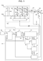
- Fig. 1 is a block diagram for showing a configuration example of a drive system for a permanent-magnet synchronous machine of a first embodiment.
- the permanent-magnet synchronous machine drive system of the first embodiment includes a permanent-magnet synchronous machine 103 to be controlled, a power converter 102 for driving the permanent-magnet synchronous machine 103, a controller 101 for controlling the power converter 102, a command generator 105 for generating a torque command Tm* of the permanent-magnet synchronous machine 103, a phase current detection unit 121 for detecting a current flowing in the permanent-magnet synchronous machine 103, a rotational position detection unit 124 for detecting a magnetic pole position of a rotor of the permanent-magnet synchronous machine 103, and a temperature detection unit 125 for detecting a magnet temperature Tmag of the permanent-magnet synchronous machine 103.
- the magnet temperature Tmag of the permanent-magnet synchronous machine 103 is an example of a value associated with the amount of magnetic flux of the permanent magnet
- the power converter 102 includes input terminals 123a and 123b for supplying power to the power converter 102, a main circuit unit 132 configured using six switching elements Sup to Swn, a gate driver 133 for directly driving the main circuit unit 132, a DC resistor 134 attached for overcurrent protection of the power converter 102, and a smoothing capacitor 131.
- the power converter 102 converts DC power supplied from the input terminals 123a and 123b into three-phase AC power, and supplies the three-phase AC power to the permanent-magnet synchronous machine 103.
- the phase current detection unit 121 detects three-phase AC currents iu and iw flowing from the power converter 102 to the permanent-magnet synchronous machine 103.
- the phase current detection unit 121 is realized by, for example, a current sensor using a Hall element. It should be noted that although the phase current detection unit 121 of Fig. 1 is configured to detect an AC current by two-phase detection, three-phase detection may be used. In addition, without using a phase current sensor, an AC current value estimated from a current value flowing in the DC resistor 134 attached for overcurrent protection of the power converter 102 may be used.
- the rotational position detection unit 124 detects a rotor position (rotational angle) of the permanent-magnet synchronous machine 103.
- the rotational position detection unit 124 is realized by, for example, a resolver, an encoder, a magnetic sensor, or the like.
- a vector control unit 112 computes a rotational speed ⁇ r of the permanent-magnet synchronous machine 103 from the detected rotational position. It should be noted that, without using a rotational position sensor or a speed sensor, a speed sensorless configuration or a position sensorless configuration may be employed by estimating the rotational speed ⁇ r or the magnetic pole position ⁇ d of the permanent-magnet synchronous machine 103 on the basis of a voltage command value, a current detection value, or the like.
- the temperature detection unit 125 detects the magnet temperature of the permanent-magnet synchronous machine 103.
- the temperature detection unit 125 is realized by, for example, a temperature sensor. It should be noted that, without using the magnet temperature itself, the temperature detecting unit 125 may detect the frame temperature of the permanent-magnet synchronous machine 103 or the coil temperature of the stator, and use a value obtained by estimating the magnet temperature Tmag of the permanent-magnet synchronous machine 103 from the frame temperature detection value or the coil temperature detection value. In addition, the magnitude of the induced voltage in accordance with the rotational speed of the permanent-magnet synchronous machine 103 may be detected or estimated to estimate the magnet temperature Tmag from the magnitude.
- the command generator 105 is a controller that generates the torque command Tm* to an AC motor and is positioned higher than the controller 101.
- the controller 101 controls the generated torque of the permanent-magnet synchronous machine 103 on the basis of the torque command Tm* of the command generator 105.
- a current controller is used to control a current flowing in the permanent-magnet synchronous machine 103, or a speed controller or a position controller is used to control a rotational speed or position.
- the controller is operated as a torque controller because the purpose is to control the torque.
- the controller 101 includes a torque correction unit 110, a current command calculation unit 111, a vector control unit 112, a polar coordinate conversion unit 113, a phase calculation unit 114, a three-phase coordinate conversion unit 115, and a PWM signal controller 116.
- the controller 101 generates a gate command signal for driving the switching elements of the power converter 102 from a calculation result of a current control system and a phase control system based on AC current detection values Iu and Iw that are detection values of the three-phase AC currents iu and iw flowing in the permanent-magnet synchronous machine 103 and the torque command Tm* from the command generator 105, and supplies the same to the gate driver 133 of the power converter 102.
- Fig. 2 is a diagram for showing definitions of coordinate systems and symbols used in control of the permanent-magnet synchronous machine 103 according to the present invention.
- the ab-axes coordinate system defined by the a-axis and the b-axis is a stator coordinate system representing the phase of the stator winding of the permanent-magnet synchronous machine 103, and the u-phase winding phase of the permanent-magnet synchronous machine 103 is generally used for the a-axis as a reference.
- the dq-axes coordinate system defined by the d-axis and the q-axis is a rotator coordinate system representing the magnetic pole position of the rotor of the permanent-magnet synchronous machine 103, and rotates in synchronization with the rotor magnetic pole position of the permanent-magnet synchronous machine 103.
- the N-pole direction of the magnetic poles of the permanent magnet attached to the rotor is generally used for the d-axis as a reference, and the d-axis is also referred to as a magnetic pole axis.
- the dc-qc axes coordinate system defined by the dc-axis and the qc-axis is the estimated phase of the rotor magnetic pole position of the permanent-magnet synchronous machine 103, that is, the coordinate system in which the controller 101 is assumed in the d-axis and q-axis directions, and is also referred to as a control axis. It should be noted that the coordinate axes combined in each coordinate system are orthogonal to each other.
- the phases of the d-axis and dc-axis with respect to the a-axis are represented as ⁇ d and ⁇ dc, respectively.
- the deviation of the dc-axis with respect to the d-axis is represented as ⁇ c. It should be noted that in the case where vector control is performed using the magnetic pole position ⁇ d of the permanent-magnet synchronous machine 103 detected by the rotational position detection unit 124, the dq-axes coordinate system and the dc-qc-axes coordinate system match each other, and the deviation ⁇ c of the dc-axis with respect to the d-axis becomes 0.
- the torque correction unit 110 outputs a torque command correction value Trq** calculated on the basis of the torque command Tm* output from the command generator 105, the magnet temperature Tmag output from the temperature detection unit 125, and current command values Idc* and Iqc* on the dc-qc-axes coordinate system output from the current command calculation unit 111.
- the current command calculation unit 111 outputs the current command values Idc* and Iqc* on the dc-qc-axes coordinate system calculated on the basis of the drive frequency ⁇ 1 of the permanent-magnet synchronous machine 103 output from the vector control unit 112, the voltage detection value Ecf of the smoothing capacitor 131, and the torque command correction value Trq** output from the torque correction unit 110.
- the vector control unit 112 separates the three-phase AC currents iu and iw that are the AC current detection values of the permanent-magnet synchronous machine 103 into torque current components (q-axis current components) and field-weakening current components (d-axis current components), and performs current control so as to match the current command values Idc* and Iqc* on the dc-qc-axes coordinate system output by the current command calculation unit 111.
- voltage command values Vdc* and Vqc* on the dc-qc-axes that are a rotational coordinate system are calculated and output.
- the vector control unit 112 also calculates and outputs the drive frequency ⁇ 1 and the control phase ⁇ dc of the permanent-magnet synchronous machine 103.
- the rotational speed ⁇ r and the magnetic pole position ⁇ d detected by the rotational position detection unit 124 may be used as the drive frequency ⁇ 1 and the control phase ⁇ dc, or the rotational speed ⁇ r and the magnetic pole position ⁇ d of the permanent-magnet synchronous machine 103 may be estimated and used on the basis of a voltage command value, a current detection value, or the like.
- the polar coordinate conversion unit 113 converts the voltage command values Vdc* and Vqc* output by the vector control unit 112 into a voltage amplitude command value V1* and a voltage command phase ⁇ and outputs the same.
- the phase calculation unit 114 adds the voltage command phase ⁇ to the control phase ⁇ dc and outputs the same as a voltage phase ⁇ v.
- the three-phase coordinate conversion unit 115 converts the voltage amplitude command value V1 output by the polar coordinate conversion unit 113 into three-phase AC voltage commands Vu*, Vv*, and Vw* on the basis of the voltage phase ⁇ v output by the phase calculation unit 114, and outputs the same to the PWM signal controller 116.
- the PWM signal controller 116 generates a triangular wave carrier on the basis of an arbitrary carrier frequency fc and the voltage detection value Ecf of the smoothing capacitor 131, compares the magnitude of the triangular wave carrier with the magnitudes of modulation waves based on the three-phase AC voltage commands Vu*, Vv*, and Vw*, and performs pulse width modulation. Switching elements of the power converter 102 are turned on/off by a gate command signal generated by the calculation result of the pulse width modulation.
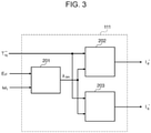
- Fig. 3 is a block diagram for showing a configuration example of the current command calculation unit 111 of the first embodiment.
- the current command calculation unit 111 includes a magnetic flux amount limit value calculation unit 201, a d-axis current command calculation unit 202, and a q-axis current command calculation unit 203.
- the current command calculation unit 111 computes and outputs the torque command correction value Trq**, the magnet temperature Tmag, the voltage detection value Ecf, and d- and q-axes current command values optimum for the fluctuation of the drive frequency ⁇ 1.
- the magnetic flux amount limit value calculation unit 201 calculates a magnetic flux amount limit value ⁇ lim serving as the limit value of the output voltage of the power converter 102, and outputs the same to the d-axis current command calculation unit 202 and the q-axis current command calculation unit 203.
- the magnetic flux amount limit value ⁇ lim may be a function proportional to the voltage detection value Ecf and inversely proportional to the drive frequency ⁇ 1.
- the magnetic flux amount limit value ⁇ lim is calculated by, for example, the following Equation (1).
- the d-axis current command calculation unit 202 calculates and outputs the d-axis current command value Idc* on the basis of the torque command correction value Trq** output from the torque correction unit 110 and the magnetic flux amount limit value ⁇ lim output from the magnetic flux amount limit value calculation unit 201.
- the q-axis current command calculation unit 203 calculates and outputs the q-axis current command value Iqc* on the basis of the torque command correction value Trq** output from the torque correction unit 110 and the magnetic flux amount limit value ⁇ lim output from the magnetic flux amount limit value calculation unit 201.
- the current command calculation unit 111 of the first embodiment calculates the ratio of the drive frequency ⁇ 1 of the permanent-magnet synchronous machine 103 to the voltage detection value Ecf of the smoothing capacitor 131 to be unified and used as the magnetic flux amount limit value Alim, so that the d- and q- axes current command calculation can be configured by reference tables into which the torque command correction value Trq** and the magnetic flux amount limit value Alim are input.
- the reference table of the d-axis current command and the reference table of the q-axis current command may be obtained and used from, for example, a test or analysis in advance.
- the reference tables set d- and q-axes current command values in a magnet temperature condition as an arbitrary reference.
- the current command calculation unit 111 suppresses the fluctuation of the output torque due to changes in the torque command and the magnet temperature by adjusting the torque command correction value Trq**, and suppresses the fluctuation of the output voltage due to changes in the rotational speed and the power supply voltage by adjusting the magnetic flux amount limit value ⁇ lim.
- the current command calculation unit 111 can separately control the fluctuation correction of the output torque with respect to the changes in the torque command, the rotational speed, the power supply voltage, and the magnet temperature and the fluctuation correction of the output voltage.
- the first embodiment can realize high-accuracy and high-response torque control by adjusting the torque command correction value Trq** by the torque correction unit 110 on the basis of the magnet temperature Tmag and the current command value to compensate the output torque of the permanent-magnet synchronous machine 103 due to the change in the magnet temperature.
- Fig. 4 is a block diagram for showing a configuration example of the torque correction unit 110 of the first embodiment.
- the torque correction unit 110 includes a torque correction coefficient calculation unit 301 and a multiplier 801.
- the torque correction unit 110 outputs a calculation result obtained by multiplying the torque command Tm* by a torque correction coefficient Ktemp* output from the torque correction coefficient calculation unit 301 as the torque command correction value Trq**.
- Fig. 5 is a block diagram for showing a configuration example of the torque correction coefficient calculation unit 301 of the first embodiment.
- the torque correction coefficient calculation unit 301 calculates and outputs the torque correction coefficient Ktemp* on the basis of the magnet temperature Tmag of the permanent-magnet synchronous machine 103 detected by the temperature detection unit 125 and the d-axis current command value Idc* and the q-axis current command value Iqc* output from the current command calculation unit 111.
- reference tables into which the magnet temperature Tmag, the d-axis current command value Idc, and the q-axis current command value Iqc* are input may be used for the calculation of the torque correction coefficient Ktemp*.
- the reference table of the torque correction coefficient Ktemp* may be obtained and used from, for example, a test or analysis in advance.
- the current command calculation unit 111 of the first embodiment is configured to be able to compute the d-and q- axes current commands optimum for the changes in the torque command, the rotational speed, and the power supply voltage.
- the torque control and the fluctuation of the output voltage due to the changes in the rotational speed and the power supply voltage can be individually controlled. Therefore, the compensation of the output torque fluctuation due to the change in the magnet temperature of the permanent-magnet synchronous machine can be performed only by adjusting the torque command values that are the inputs to the d-axis current command calculation unit 202 and the q-axis current command calculation unit 203.
- Fig. 6 is a graph for exemplifying a relationship between the d- and q-axes currents of the permanent-magnet synchronous machine and the output torques at a reference temperature TmagO.
- the horizontal axis represents the d-axis current id flowing in the permanent-magnet synchronous machine
- the vertical axis represents the q-axis current iq flowing in the permanent-magnet synchronous machine
- the magnitudes of the torques output by the permanent-magnet synchronous machine are represented by contour lines. It should be noted that the contour lines representing the magnitudes of the output torques assume that the output torque becomes larger in the order of A ⁇ B ⁇ C ⁇ D ⁇ E. In the arbitrary magnet temperature condition of Fig.
- the magnitude of the output torque is C.
- the magnet temperature condition at this time is assumed to be the reference temperature TmagO.
- Fig. 7 is a graph for exemplifying a relationship between the d- and q-axes currents of the permanent-magnet synchronous machine and the output torques at a magnet temperature condition higher than the reference temperature TmagO.
- the torque map shown in Fig. 7 in the case where the current of the permanent-magnet synchronous machine is controlled at the Z point of the d-axis current and the q-axis current same as Fig. 6 , it can be understood that the magnitudes of the output torques become smaller than that of C.
- Fig. 8 is a graph for exemplifying a relationship between the d- and q-axes currents of the permanent-magnet synchronous machine and the output torques at a magnet temperature condition lower than the reference temperature Tmag0.
- the current of the permanent-magnet synchronous machine is controlled at the Z point of the d-axis current and the q-axis current same as Fig. 6 and Fig. 7 , it can be understood that the magnitudes of the output torques become larger than that of C.
- the amount of magnetic flux of the permanent magnet changes due to the temperature change of the permanent magnet, and the output torque fluctuates even if the drive device is controlled at the same current operating point in accordance with the torque command.
- the torque correction unit 110 computes the torque correction coefficient Ktemp* on the basis of the magnet temperature Tmag, the d-axis current command value Idc*, and the q-axis current command value Iqc*, and corrects the torque command Tm* by using the torque correction coefficient Ktemp*, so that the fluctuation of the output torque due to the change in the magnet temperature of the permanent-magnet synchronous machine is compensated.
- Fig. 9 is a graph for exemplifying a relationship of the output torque ratio of the output torque at the reference temperature TmagO to the d- and q-axes currents of the permanent-magnet synchronous machine at a magnet temperature condition higher than the reference temperature TmagO.
- Fig. 9 shows the ratio of the output torque at the reference temperature TmagO in Fig. 6 to the output torque at the magnet temperature higher than the reference temperature TmagO in Fig. 7 as a table map of the d-axis current id and the q-axis current iq.
- the torque correction coefficient Ktemp* of the torque correction unit 110 is based on the output torque at the reference temperature TmagO same as the computation condition of the d-axis current command calculation unit 202 and the q-axis current command calculation unit 203 of the current command calculation unit 111, and the ratio of the output torque in accordance with the change in the magnet temperature is provided as a reference table, so that the output torque fluctuation due to the change in the magnet temperature can be compensated.
- the output torque fluctuation due to the change in the magnet temperature can be compensated by adjusting the torque command values as the inputs of the d- and q-axes current command calculation in accordance with the magnet temperature.
- the first embodiment shows a configuration example in which three-dimensional table data for outputting the torque correction coefficient Ktemp* by inputting the magnet temperature Tmag, the d-axis current command value Idc*, and the q-axis current command value Iqc* is used in the torque correction coefficient calculation unit 301 of the torque correction unit 110.
- the use of multidimensional table data enables torque compensation control with higher accuracy because complex state changes with respect to changes in a plurality of inputs can be considered.
- the table data of three dimensions or more causes problems such as an increase in test, analysis, and adjustment time for computing the d-and q-axes current command values and an increase in the memory capacity of the control device and the calculation load of the table reference.
- Fig. 10 is a block diagram for showing a configuration example of a torque correction coefficient calculation unit 301b as a modified example of the first embodiment.
- the first embodiment can also be realized by using the torque correction coefficient calculation unit 301b that does not use a three-dimensional reference table, instead of the torque correction coefficient calculation unit 301 that uses a three-dimensional reference table for computing the torque correction coefficient Ktemp* in accordance with the magnet temperature, the d-axis current command, and the q-axis current command.
- the torque correction coefficient calculation unit 301b includes a magnet temperature dependent torque correction coefficient calculation unit 401b, a reluctance torque ratio correction coefficient calculation unit 402b, and an adder 802b.
- the torque correction coefficient calculation unit 301b outputs a value obtained by adding a torque correction coefficient Ktemp1* output from the magnet temperature dependent torque correction coefficient calculation unit 401a to a torque correction coefficient Ktemp2* output from the reluctance torque ratio correction coefficient calculation unit 402b as the torque correction coefficient Ktemp*.
- the magnet temperature dependent torque correction coefficient calculation unit 401b computes, on the basis of the magnet temperature Tmag, a coefficient corresponding to the amount of change in magnet torque due to a change in magnet temperature using the reference temperature TmagO as a reference, and outputs the same as the torque correction coefficient Ktemp1*. Since the magnet torque is proportional to the magnitude of the magnet magnetic flux of the permanent-magnet synchronous machine, the amount of change in magnet magnetic flux in accordance with the magnet temperature Tmag may be computed, and the torque correction coefficient Ktemp1* corresponding to the amount of change in magnet torque may be calculated using the reference temperature TmagO as a reference.
- Fig. 11 is a block diagram for showing a configuration example of the reluctance torque ratio correction coefficient calculation unit 402b as a modified example of the first embodiment.
- the reluctance torque ratio correction coefficient calculation unit 402b includes a reluctance torque ratio magnet temperature correction unit 501b, a reluctance torque estimation calculation unit 502b, and a multiplier 803b.
- the reluctance torque ratio correction coefficient calculation unit 402b computes a coefficient corresponding to the amount of change in the ratio of magnet torque to reluctance at arbitrary current operating points of Idc* and Iqc* due to a change in magnet temperature using the reference temperature TmagO as a reference, and outputs the same as the torque correction coefficient Ktemp2*.
- the reluctance torque ratio magnet temperature correction unit 501b outputs a coefficient for correcting the ratio of reluctance torque to magnet torque to the multiplier 803b on the basis of the reference temperature TmagO.
- the reluctance torque estimation calculation unit 502b estimates and calculates the reluctance torque on the basis of the d-axis current command value Idc* and the q-axis current command value Iqc*, and outputs the same to the multiplier 803b.
- the reluctance torque ratio correction coefficient calculation unit 402b can compute the torque correction coefficient Ktemp2* in accordance with the changes in the magnet temperature Tmag, the d-axis current command value Idc*, and the q-axis current command value Iqc* without using the three-dimensional table. Since the torque is corrected in accordance with the optimum d- and q-axes current command values that vary due to the change in the magnet temperature of the permanent-magnet synchronous machine and the changes in the torque command, the rotational speed, and the power supply voltage, high-efficiency and high-accuracy torque control can be realized in the case where the magnet temperature changes.
- the reluctance torque is 0, and thus the reluctance torque ratio correction coefficient calculation unit 402b is not required.
- a d-axis current detection value Idc and a q-axis current detection value Iqc can be used instead of the d-axis current command value Idc* and the q-axis current command value Iqc*.
- the torque command can be used instead of the d-axis current command value Idc* and the q-axis current command value Iqc* that are the inputs to the reluctance torque ratio correction coefficient calculation unit 402b.
- the torque correction coefficient calculation unit 301 of the first embodiment can be implemented if the fluctuation ratio of the output torque due to the change in the magnet temperature of the permanent-magnet synchronous machine at the same id and iq current operating point is output as the torque correction coefficient Ktemp* by using the reference temperature TmagO of the d-axis current command calculation unit 202 and the q-axis current command calculation unit 203 of the current command calculation unit 111 as a reference.
- Equation (2) the magnitude of the output torque Tm of the permanent-magnet synchronous machine is represented by Equation (2).
- Equation (2) the magnitude of the magnet magnetic flux of the permanent-magnet synchronous machine is ⁇ m
- the d-axis inductance is Ld
- the q-axis inductance is Lq
- the number of pole pairs is Pm
- the d-axis current flowing in the permanent-magnet synchronous machine is id
- the q-axis current is iq.
- the first term on the right side of Equation (2) is magnet torque and the second term on the right side is reluctance torque.
- the torque correction coefficient calculation unit 301 calculates the torque correction coefficient Ktemp* by estimating, as the magnet magnetic flux of the permanent-magnet synchronous machine at the reference temperature TmagO is ⁇ m0 and the magnet magnetic flux of the permanent-magnet synchronous machine at the magnet temperature Tmag is ⁇ m', the fluctuation of the output torque due to a change in magnet temperature in the case where current control is performed using the d-axis current command value Idc* and the q-axis current command value Iqc*.
- the torque correction coefficient Ktemp* is calculated by, for example, the following Equation (3).
- K temp ⁇ P m ⁇ m 0 I qc ⁇ + L d ⁇ L q I dc ⁇ I qc ⁇ P m ⁇ m ′ I qc ⁇ + L d ⁇ L q I dc ⁇ I qc ⁇
- the magnet magnetic flux ⁇ m' of the permanent-magnet synchronous machine at the magnet temperature Tmag may be a function based on Tmag, and is calculated by, for example, the following Equation (4).
- the temperature coefficient needs to be changed depending on the type and characteristics of the permanent magnet used for the permanent magnet synchronization.
- Equation (3) since the d-axis inductance Ld and the q-axis inductance Lq have characteristics of being changed non-linearly with respect to the d-axis current and the q-axis current, the output torque accuracy by the torque correction of the embodiment can be improved by computing the inductance value on the basis of the d-axis current command value Idc* and the q-axis current command value Iqc* or the d-axis current detection value Idc and the q-axis current detection value Iqc.
- the torque correction coefficient calculation unit 301 or 301b calculates the torque correction coefficient Ktemp* and computes the torque command correction value Trq** by multiplying the torque correction coefficient Ktemp* by the torque command Tm* from the command generator 105 in the torque correction unit 110 in the embodiment, a torque compensation amount ⁇ Trq-mag* based on the magnet temperature Tmag, the d-axis current command value Idc*, and the q-axis current command value Iqc* is computed, and the torque compensation amount ⁇ Trq-mag* may be added to the torque command Tm* to compute and use the torque command correction value Trq**.
- Fig. 12 is a block diagram for showing a configuration example of the torque correction unit 110c as a modified example of the first embodiment.
- the first embodiment can also be realized by using the torque correction unit 110c instead of the torque correction unit 110 by computing the amount of correction for the output torque due to the change in the magnet temperature of the permanent-magnet synchronous machine and adding the same to the torque command Tm* from the command generator 105 in the calculation of the torque command correction value Trq** in accordance with the changes in the torque command, the magnet temperature, the d-axis current command, and the q-axis current command.
- the torque correction unit 110c includes a torque compensation amount calculation unit 302c and an adder 804c.
- the torque correction unit 110c computes the torque compensation amount ⁇ Trq-mag* on the basis of the magnet temperature Tmag, the d-axis current command value Idc*, and the q-axis current command value Iqc* in the torque compensation amount calculation unit 302c, and outputs a calculation result obtained by adding the torque compensation amount ⁇ Trq-mag* to the torque command Tm* as the torque command correction value Trq**.
- the torque compensation amount calculation unit 302c can be realized if the fluctuation amount of the output torque due to the change in the magnet temperature of the permanent-magnet synchronous machine at the same id and iq current operating point using the reference temperature TmagO as a reference instead of the torque correction coefficient Ktemp* to be output is computed in the torque correction coefficient calculation unit 301 or 301b, and is output as the torque compensation amount ⁇ Trq-mag*.
- the torque command value is corrected on the basis of the magnet temperature and the current command value of the permanent-magnet synchronous machine, so that the output torque fluctuation due to the change in magnet temperature is compensated. Accordingly, the torque accuracy and the torque control response when the magnet temperature fluctuates can be improved with a simpler configuration.
- the magnetic flux amount limit value ⁇ lim is computed on the basis of the magnet temperature Tmag of the permanent-magnet synchronous machine 103 output from the temperature detection unit 125 in addition to the voltage detection value Ecf of the smoothing capacitor 131 and the drive frequency ⁇ 1 of the permanent-magnet synchronous machine 103 output from the vector control unit 112.
- Fig. 13 is a block diagram for showing a configuration example of a drive system for a permanent-magnet synchronous machine of a second embodiment. In the description of the second embodiment, only different parts will be described in comparison with the first embodiment shown in Fig. 1 .
- the drive device for the permanent-magnet synchronous machine of the second embodiment can be realized by using a current command calculation unit 111d instead of the current command calculation unit 111 of the first embodiment in Fig. 1 .
- Fig. 14 is a block diagram for showing a configuration example of the current command calculation unit 111d of the second embodiment.
- the current command calculation unit 111d includes a magnetic flux amount limit value calculation unit 601d, the d-axis current command calculation unit 202, and the q-axis current command calculation unit 203.
- the magnetic flux amount limit value calculation unit 601d calculates the magnetic flux amount limit value ⁇ lim on the basis of the voltage detection value Ecf of the smoothing capacitor 131, the drive frequency ⁇ 1 of the permanent-magnet synchronous machine 103 output from the vector control unit 112, and the magnet temperature Tmag of the permanent-magnet synchronous machine 103 output from the temperature detection unit 125, and outputs the same to the d-axis current command calculation unit 202 and the q-axis current command calculation unit 203.
- the magnetic flux amount limit value Alim that is an input variable of the d-axis current command calculation unit 202 and the q-axis current command calculation unit 203 may be obtained by adding a correction value in accordance with an increase or decrease in magnet magnetic flux caused by a change in magnet temperature to the ratio of the voltage detection value Ecf to the drive frequency ⁇ 1.
- the following Equation (5) is used for calculation.
- the magnet temperature Tmag of the permanent-magnet synchronous machine, the reference temperature TmagO set in the calculation of the d-axis current command calculation unit 202 and the q-axis current command calculation unit 203, and the first term on the right side calculated on the basis of the correction coefficient Kv correspond to the correction value of the magnetic flux amount limit value in accordance with an increase or decrease in the magnet magnetic flux due to the change in magnet temperature.
- the correction coefficient Kv may be a constant, or may be calculated as a function expression of the magnet temperature Tmag.
- the magnetic flux amount limit value ⁇ lim may be obtained by multiplying the ratio of the voltage detection value Ecf to the drive frequency ⁇ 1 by a correction coefficient in accordance with the magnet temperature Tmag.
- Equation (6) is used for calculation.
- the correction coefficient Kv' may be a constant, or may be calculated as a function expression of the magnet temperature Tmag.
- the current command calculation unit 111d of the second embodiment has the same configuration as that of the current command calculation unit 111 of the first embodiment except for the magnetic flux amount limit value calculation unit 601d.
- the calculation of the d-axis current command and the q-axis current command in consideration of the fluctuation of the output voltage due to the change in magnet temperature can be realized by adjusting the magnetic flux amount limit value ⁇ lim on the basis of the magnet temperature, and it is possible to achieve the high efficiency of the drive device for the permanent-magnet synchronous machine.
- the magnetic flux amount limit value ⁇ lim is computed on the basis of a target limit modulation factor Ymf* for controlling an output voltage limit value V1lim of the power converter 102 in addition to the voltage detection value Ecf of the smoothing capacitor 131 and the drive frequency ⁇ 1 of the permanent-magnet synchronous machine 103 output from the vector control unit 112.
- Fig. 15 is a block diagram for showing a configuration example of a drive system for a permanent-magnet synchronous machine of a third embodiment. Only different parts will be described in comparison with the first embodiment shown in Fig. 1 .
- the drive device for the permanent-magnet synchronous machine of the third embodiment can be realized by using a current command calculation unit 111e and a vector control unit 112e instead of the current command calculation unit 111 and the vector control unit 112 of the first embodiment in Fig. 1 .
- Fig. 16 is a block diagram for showing a configuration example of the current command calculation unit 111e of the third embodiment.
- the current command calculation unit 111e includes a magnetic flux amount limit value calculation unit 601e, a d-axis current command calculation unit 202, and a q-axis current command calculation unit 203.
- the magnetic flux amount limit value calculation unit 601e calculates the magnetic flux amount limit value ⁇ lim on the basis of the voltage detection value Ecf of the smoothing capacitor 131, the drive frequency ⁇ 1 of the permanent-magnet synchronous machine 103 output from the vector control unit 112e, and the target limit modulation factor Ymf* for controlling the output voltage limit value V1lim of the power converter 102 output from the vector control unit 112e, and outputs the same to the d-axis current command calculation unit 202 and the q-axis current command calculation unit 203.
- the output voltage control value V1lim is calculated by, for example, the following Equation (7).
- V 1 lim E cf 0 2 K , 4 ⁇ ⁇ Y mf ⁇
- the target limit modulation factor Ymf* is set to a value equal to or smaller than 1 and the power converter 102 performs PWM control with one synchronous pulse for obtaining an output voltage maximum value
- the target limit modulation factor Ymf* becomes 1.
- Ecf0 is a reference value of the DC voltage of the smoothing capacitor 131 for determining the output voltage control value V1lim.
- the target limit modulation factor Ymf* may be, for example, a target modulation factor based on a target voltage value of field-weakening control in the case where the field-weakening control is performed by the vector control unit 112e in order to control the output voltage limit value V1lim.
- the target limit modulation factor Ymf* may be a target modulation factor determined from the operating conditions of the PWM control.
- the magnetic flux amount limit value ⁇ lim that is an input variable of the d-axis current command calculation unit 202 and the q-axis current command calculation unit 203 in the magnetic flux amount limit value calculation unit 601d may be obtained by multiplying the ratio of the voltage detection value Ecf to the drive frequency ⁇ 1 by the target limit modulation factor Ymf* of the power converter 102.
- the following Equation (8) is used for calculation.
- the current command calculation unit 111e of the second embodiment has the same configuration as that of the current command calculation unit 111 of the first embodiment except for the magnetic flux amount limit value calculation unit 601e.
- the calculation of the d-axis current command and the q-axis current command in consideration of the output voltage of the power converter and the fluctuation of the output voltage due to the restriction of the PWM control calculation can be realized by adjusting the magnetic flux amount limit value ⁇ lim on the basis of the limit value of the output voltage of the power converter 102, and it is possible to achieve the high efficiency of the drive device for the permanent-magnet synchronous machine in accordance with the specifications, performance, and operating conditions of the power converter and the controller.
- a three-dimensional table computed in advance by a test or simulation analysis on the basis of the voltage detection value Ecf of the smoothing capacitor 131, the drive frequency ⁇ 1 of the permanent-magnet synchronous machine 103 output from the vector control unit 112, and the torque command correction value Trq** output from the torque correction unit 110 is used.
- Fig. 17 is a block diagram for showing a configuration example of a current command calculation unit 111f of the fourth embodiment.
- the drive device for the permanent-magnet synchronous machine of the fourth embodiment can be realized by using the current command calculation unit 111f instead of the current command calculation unit 111 of the first embodiment in Fig. 1 . Only different parts of the configuration will be described in comparison with the first embodiment shown in Fig. 1 .
- the current command calculation unit 111f includes a d-axis current command three-dimensional table reference unit 701f and a q-axis current command three-dimensional table reference unit 702f.
- the d-axis current command three-dimensional table calculation unit 701f calculates and outputs the d-axis current command value Idc* on the basis of the voltage detection value Ecf of the smoothing capacitor 131, the drive frequency ⁇ 1 of the permanent-magnet synchronous machine 103 output from the vector control unit 112, and the torque command correction value Trq** output from the torque correction unit 110.
- the q-axis current command three-dimensional table reference unit 702f calculates and outputs the q-axis current command value Iqc* on the basis of the voltage detection value Ecf of the smoothing capacitor 131, the drive frequency ⁇ 1 of the permanent-magnet synchronous machine 103 output from the vector control unit 112, and the torque command correction value Trq** output from the torque correction unit 110.
- the three-dimensional table data used for the computation of the d-axis current command value Idc* and the q-axis current command value Iqc* in the d-axis current command three-dimensional table calculation unit 701f and the q-axis current command three-dimensional table reference unit 702f can be realized by previously obtaining the d-axis current command and the q-axis current command optimum for the changes in the torque command, the rotational speed, and the power supply voltage using the reference temperature TmagO of the permanent magnet as the set value of the magnet temperature condition by a tests, simulation analysis, or the like.
- the d-axis current command value Idc* and the q-axis current command are computed for the changes in the torque command, the rotational speed, and the power supply voltage by using the three-dimensional table data, but may be obtained by using an arithmetic expression.
- the calculation of the d-axis current command value Idc* and the q-axis current command value Iqc* optimum for the changes in the torque command, the rotational speed, and the power supply voltage can be realized by calculating the d-axis current command and the q-axis current command on the basis of the three-dimensional table data obtained in advance by a test, analysis, or the like, and it is possible to achieve the high efficiency of the drive device for the permanent-magnet synchronous machine.
- the torque correction coefficient Ktemp* is computed on the basis of the magnet temperature Tmag of the permanent-magnet synchronous machine 103 detected by the temperature detection unit 125 and the d-axis current command value Idc* output from the current command calculation unit 111.
- the torque command correction value Trq** for the change in magnet temperature can be calculated without using the multidimensional table, and it is possible to realize the drive device of the permanent-magnet synchronous machine that is less in the calculation load of the control device than that of the first embodiment and can save memory capacity.
- Fig. 18 is a block diagram for showing a configuration example of a drive system for a permanent-magnet synchronous machine of a fifth embodiment. In the description of the fifth embodiment, only different parts will be described in comparison with the first embodiment shown in Fig. 1 .
- the drive device for the permanent-magnet synchronous machine of the fifth embodiment can be realized by using a torque correction unit 110g instead of the torque correction unit 110 of the first embodiment in Fig. 1 .
- Fig. 19 is a block diagram for showing a configuration example of the torque correction unit 110g of the fifth embodiment.
- the torque correction unit 110g includes a torque correction coefficient calculation unit 301g and a multiplier 801g.
- the torque correction unit 110g outputs, as the torque command correction value Trq**, a calculation result obtained by multiplying the torque command Tm* by the torque correction coefficient Ktemp* output from the torque correction coefficient calculation unit 301g.
- Fig. 20 is a block diagram for showing a configuration example of the torque correction coefficient calculation unit 301g of the fifth embodiment.
- the torque correction coefficient calculation unit 301g includes a magnet temperature compensation coefficient calculation unit 901g and a d-axis current characteristic compensation coefficient calculation unit 902g.
- the torque correction coefficient calculation unit 301g calculates and outputs the torque correction coefficient Ktemp* on the basis of the magnet temperature Tmag of the permanent-magnet synchronous machine 103 detected by the temperature detection unit 125 and the d-axis current command value Idc* output from the current command calculation unit 111.
- the magnet temperature compensation coefficient calculation unit 901g computes, on the basis of the magnet temperature Tmag, a coefficient corresponding to the amount of change in output torque due to a change in magnet temperature using the reference temperature TmagO as a reference, and outputs the same as a torque correction coefficient Ktemp-mag*.
- the ratio of the output torque at the reference temperature TmagO to the output torque at the magnet temperature higher than the reference temperature TmagO is shown in Fig. 9 as a table map of the d-axis current id and the q-axis current iq and is used as correction means for torque commands in the first embodiment, it can be understood that the magnitude of the output torque ratio based on the temperature change of the permanent magnet has a stronger correlation with the magnitude of the d-axis current than that of the q-axis current as shown in FIG. 9 .
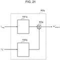
- Fig. 21 is a block diagram for showing a configuration example of the d-axis current characteristic compensation coefficient calculation unit 902g of the fifth embodiment.
- the d-axis current characteristic compensation coefficient calculation unit 902g includes a d-axis current characteristic magnet temperature correction coefficient calculation unit 1001g, a d-axis current characteristic coefficient calculation unit 1002g, and a multiplier 803g.
- the d-axis current characteristic compensation coefficient calculation unit 902g computes a coefficient corresponding to the amount of change in the ratio of magnet torque to reluctance at arbitrary current operating points of Idc* and Iqc* due to a change in magnet temperature using the reference temperature TmagO as a reference, and outputs the same as a torque correction coefficient Ktemp-id*.
- the d-axis current characteristic magnet temperature correction coefficient calculation unit 1001g On the basis of the reference temperature TmagO, the d-axis current characteristic magnet temperature correction coefficient calculation unit 1001g outputs a coefficient for correcting the fluctuation of the characteristic amount of the output torque ratio dependent on the d-axis current according to the magnet temperature to the multiplier 803b.
- the d-axis current characteristic coefficient calculation unit 1002g calculates a coefficient for correcting the amount of change of the output torque ratio dependent on the d-axis current on the basis of the d-axis current command value Idc*, and outputs the same to the multiplier 803b.
- the d-axis current characteristic compensation coefficient calculation unit 902g can calculate the torque correction coefficient Ktemp-id* without using the multidimensional table.
- the coefficient corresponding to the change in the ratio of magnet torque to reluctance torque due to the changes in the temperature of the permanent magnet and the operating conditions is calculated on the basis of the d-axis current command and the magnet temperature, so that the calculation of the torque command correction value can be realized without using the multidimensional table, and the calculation load of the drive device for the permanent-magnet synchronous machine can be reduced and the memory capacity can be saved.
- the fifth embodiment has been described above. Although the fifth embodiment has been described by mainly using the first embodiment for the purpose of description, the second to fourth embodiments can be similarly applied as the basic configurations.
- the torque command is compensated by using the output loss of the drive device such as the mechanical loss and the iron loss of the permanent-magnet synchronous machine as loss torque, so that the drive device for the permanent-magnet synchronous machine that can perform torque control with higher accuracy than in the first embodiment can be realized.
- Fig. 22 is a block diagram for showing a configuration example of a drive system for a permanent-magnet synchronous machine of the sixth embodiment. Only different parts will be described in comparison with the first embodiment shown in Fig. 1 .
- the drive device for the permanent-magnet synchronous machine of the sixth embodiment can be realized by adding a torque command loss compensation unit 117h to the first embodiment in Fig. 1 .
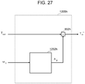
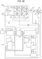
- Fig. 23 is a block diagram for showing a configuration example of the torque command loss compensation unit 117h of the sixth embodiment.
- the torque command loss compensation unit 117h includes an iron loss calculation unit 1201h, a mechanical loss calculation unit 1202h, a load loss calculation unit 1203h, a loss torque conversion unit 1204h, an output adjustment unit 1205h, and adders 1206h, 1207h, and 1208h.
- the iron loss calculation unit 1201h calculates and outputs an iron loss Wi on the basis of the drive frequency ⁇ 1 of the permanent-magnet synchronous machine 103 output from the vector control unit 112 and the voltage amplitude command value V1* output from the polar coordinate conversion unit 113.
- the mechanical loss calculation unit 1202h calculates and outputs a mechanical loss Wm on the basis of the drive frequency ⁇ 1 of the permanent-magnet synchronous machine 103 output from the vector control unit 112.
- the load loss calculation unit 1203h calculates and outputs a load loss Wl on the basis of the torque command Tm* output from the command generator 105 and the drive frequency ⁇ 1 of the permanent-magnet synchronous machine 103 output from the vector control unit 112.
- the adders 1206h and 1207h add the iron loss Wi output from the iron loss calculation unit 1201h, the mechanical loss Wm output from the mechanical loss calculation unit 1202h, and the load loss Wl output from the load loss calculation unit 1203h, and output an output loss Wloss.
- the loss torque conversion unit 1204h converts the output loss Wloss into torque on the basis of the drive frequency ⁇ 1 of the permanent-magnet synchronous machine 103 output from the vector control unit 112, and outputs a loss torque Tloss.
- the adder 1208h adds the loss torque Tloss output from the loss torque conversion unit 1204h to the torque command Tm* output from the command generator 105, and outputs a motor output torque Tout.
- the output adjustment unit 1205h calculates a torque command Tm** on the basis of the motor output torque Tout output from the adder 1208h and the drive frequency ⁇ 1 of the permanent-magnet synchronous machine 103 output from the vector control unit 112, and outputs the same to the torque correction unit 110.
- the iron loss calculation unit 1201h the mechanical loss calculation unit 1202h, the load loss calculation unit 1203h, the loss torque conversion unit 1204h, and the output adjustment unit 1205h that are characteristic parts of the sixth embodiment will be described in detail.
- Fig. 24 is a block diagram for showing a configuration example of the iron loss calculation unit 1201h of the sixth embodiment.
- the iron loss calculation unit 1201h includes a hysteresis loss calculation unit 1211h, an eddy current loss calculation unit 1212h, and an adder 813h.
- the hysteresis loss calculation unit 1211h calculates and outputs a hysteresis loss Wh on the basis of the drive frequency ⁇ 1 of the permanent-magnet synchronous machine 103 output from the vector control unit 112 and the voltage amplitude command value V1* output from the polar coordinate conversion unit 113.
- the hysteresis loss Wh is calculated by, for example, the following Equation (9).
- a hysteresis loss coefficient kh and a magnetic flux density coefficient kB are values determined on the basis of the material and structure of the permanent-magnet synchronous machine 103, and any of a design value, an analysis value, and an actual measurement value may be used.
- the hysteresis loss calculation unit 1211h may be configured to use a two-dimensional table for outputting the hysteresis loss Wh obtained in advance from actual measurement or analysis by using the drive frequency ⁇ 1 and the voltage amplitude command value V1* as input variables.
- the eddy current loss calculation unit 1212h calculates and outputs an eddy current loss We on the basis of the voltage amplitude command value V1* output from the polar coordinate conversion unit 113.
- the eddy current loss We is calculated by, for example, the following Equation (10).
- an eddy current loss coefficient ke and the magnetic flux density coefficient kB are values determined on the basis of the material and structure of the permanent-magnet synchronous machine 103, and any of a design value, an analysis value, and an actual measurement value may be used.
- the eddy current loss calculation unit 1212h may be configured to use a one-dimensional table for outputting the eddy current loss We obtained in advance from actual measurement or analysis by using the voltage amplitude command value V1* as an input variable.
- the adder 813h adds the hysteresis loss Wh output from the hysteresis loss calculation unit 1211h and the eddy current loss We output from the eddy current loss calculation unit 1212h, and outputs the iron loss Wi.
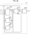
- Fig. 25 is a block diagram for showing a configuration example of the mechanical loss calculation unit 1202h of the sixth embodiment.
- the mechanical loss calculation unit 1202h includes a bearing loss calculation unit 1221h, a wind loss calculation unit 1222h, and an adder 823h.
- the bearing loss calculation unit 1221h calculates and outputs a bearing loss Wb on the basis of the drive frequency ⁇ 1 (electric angular frequency) of the permanent-magnet synchronous machine 103 output from the vector control unit 112.
- the bearing loss Wb has a characteristic proportional to the first power of the motor rotational speed (machine angular frequency), and is calculated by, for example, the following Equation (11).
- a bearing loss coefficient kb is a value determined on the basis of the material and structure of a bearing portion of the permanent-magnet synchronous machine 103, and any of a design value, an analysis value, and an actual measurement value may be used.
- the bearing loss calculation unit 1221h may be configured to use a one-dimensional table for outputting the bearing loss Wb obtained in advance from actual measurement or analysis by using the drive frequency ⁇ 1 (electric angular frequency) or the motor rotational speed (machine angular frequency) as an input variable.
- the wind loss calculation unit 1222h calculates and outputs a wind loss Ww on the basis of the drive frequency ⁇ 1 (electric angular frequency) of the permanent-magnet synchronous machine 103 output from the vector control unit 112.
- the wind loss Ww has a characteristic proportional to the cube of the motor rotational speed (machine angular frequency) and is calculated by, for example, the following Equation (12).
- a wind loss coefficient kw is a value determined on the basis of the material and structure of a rotating portion of the permanent-magnet synchronous machine 103, the frictional resistance with air, and the like, and any of a design value, an analysis value, and an actual measurement value may be used.
- the wind loss calculation unit 1222h may be configured to use a one-dimensional table for outputting the wind loss Ww obtained in advance from actual measurement or analysis by using the drive frequency ⁇ 1 (electric angular frequency) or the motor rotational speed (machine angular frequency) as an input variable.
- the adder 823h adds the bearing loss Wb output from the bearing loss calculation unit 1221h and the wind loss Ww output from the wind loss calculation unit 1222h, and outputs the mechanical loss Wm.
- Fig. 26 is a block diagram for showing a configuration example of the load loss calculation unit 1203h of the sixth embodiment.
- the load loss calculation unit 1203h includes a stray load loss calculation unit 1231h, an external load loss calculation unit 1232h, and an adder 833h.
- the stray load loss calculation unit 1231h calculates and outputs a stray load loss Ws on the basis of the torque command Tm* output from the command generator 105 and the drive frequency ⁇ 1 of the permanent-magnet synchronous machine 103 output from the vector control unit 112.
- the stray load loss is a loss that is not included in the copper loss, the iron loss, and the mechanical loss, and is a slight loss that is difficult to compute accurately.
- the stray load loss Ws is calculated by, for example, the following Equation (13).
- a stray load loss coefficient ks can be set to an arbitrary value.
- the value is determined by the following Equation (14) using a rated output Pr of the permanent-magnet synchronous machine 103.
- the stray load loss calculation unit 1231h may be configured to use a two-dimensional table for outputting the stray load loss Ws obtained in advance from actual measurement or analysis by using the torque command Tm* and the drive frequency ⁇ 1 as input variables.
- the external load loss calculation unit 1232h calculates and outputs an external load loss Wo on the basis of the torque command Tm* output from the command generator 105 and the drive frequency ⁇ 1 of the permanent-magnet synchronous machine 103 output from the vector control unit 112.
- the external load loss Wo is used to compensate the fluctuation of the load state of the load characteristic connected to the permanent-magnet synchronous machine 103 according to the output torque and the rotational speed, and is determined according to the type and application of the load of the drive device such as a constant torque load of a conveyor, a crane, or the like, a square reduction load of a fan, a pump, or the like, or a constant output load of a winding machine or the like.
- the external load loss calculation unit 1232h can be realized with a configuration using a two-dimensional table for outputting the external load loss Wo obtained in advance from actual measurement or analysis by using the torque command Tm* and the drive frequency ⁇ 1 as input variables. It should be noted that in the case where these load characteristics are considered in the torque command Tm* output from the command generator 105, the external load loss Wo may be set to 0.
- the adder 833h adds the stray load loss Wr output from the stray load loss calculation unit 1231h and the external load loss Wo output from the external load loss calculation unit 1232h, and outputs the load loss Wi.
- the loss torque conversion unit 1204h calculates and outputs the loss torque Tloss on the basis of the output loss Wloss that is the total value of the iron loss Wi, the mechanical loss Wm, and the load loss Wl and the drive frequency ⁇ 1 of the permanent-magnet synchronous machine 103 output from the vector control unit 112.
- the loss torque Tloss is calculated by, for example, the following Equation (15).
- Fig. 27 is a block diagram for showing a configuration example of the output adjustment unit 1205h of the sixth embodiment. As shown in Fig. 27 , the output adjustment unit 1205h includes a gear efficiency calculation unit 1252h and a divider 852h.
- the gear efficiency calculation unit 1252h calculates and outputs a gear efficiency ⁇ g on the basis of the drive frequency ⁇ 1 of the permanent-magnet synchronous machine 103 output from the vector control unit 112.
- the gear efficiency ⁇ g may be configured to use a one-dimensional table for outputting the gear efficiency ⁇ g obtained in advance from actual measurement or analysis by using, for example, the drive frequency ⁇ 1 as an input variable.
- the gear efficiency ⁇ g may be used as a constant or may be calculated as a function expression of the drive frequency ⁇ 1.
- the gear efficiency ⁇ g is a value determined on the basis of the frictional resistance of bearings or gears of the permanent-magnet synchronous machine 103, the resistance of a lubricating oil, or the like, and any of a design value, an analysis value, and an actual measurement value may be used.
- the output adjustment unit 1205h may be excluded from the torque command loss compensation unit 117h or the gear efficiency ⁇ g output from the gear efficiency calculation unit 1252h may be always set to 1.
- the divider 852h divides the motor output torque Tout that is the total value of the torque command Tm* and the loss torque Tloss by the gear efficiency ⁇ g output from the gear efficiency calculation unit 1252h, and outputs the torque command Tm**.
- the calculation of the torque command correction value in consideration of the loss torque of the drive device for the permanent-magnet synchronous machine can be realized, and the high accuracy of the torque control of the drive device for the permanent-magnet synchronous machine can be realized.
- hysteresis loss Wh the eddy current loss We
- the bearing loss Wb the wind loss Ww
- the stray load loss Ws the external load loss Wo are used in the calculation of the output loss Wloss, so that the reduction of the output torque of the motor due to the loss torque to the torque command is compensated, and the high accuracy of the torque control can be realized.
- the iron loss calculation unit 1201h of the sixth embodiment can be also realized by using the d-axis current command value Idc* and the q-axis current command value Iqc* output from the current command calculation unit 111 instead of the voltage amplitude command value V1* output from the polar coordinate conversion unit 113.
- Fig. 28 is a block diagram for showing a configuration example of a drive system for a permanent-magnet synchronous machine as a modified example of the sixth embodiment.
- a configuration example of a drive system for a permanent-magnet synchronous machine as a modified example of the sixth embodiment.
- only different parts of the configuration will be described in comparison with the configuration example of the sixth embodiment shown in Fig. 22 .
- the modified example of the configuration of the drive device for the permanent-magnet synchronous machine of the sixth embodiment can be realized by using a torque command loss compensation unit 117i instead of the torque command loss compensation unit 117h of the sixth embodiment in Fig. 22 .
- Fig. 29 is a block diagram for showing a configuration example of the torque command loss compensation unit 117i as the modified example of the sixth embodiment. As shown in Fig. 29 , the torque command loss compensation unit 117i can be realized by using an iron loss calculation unit 1201i instead of the iron loss calculation unit 1201h.
- the iron loss calculation unit 1201i calculates and outputs the iron loss Wi on the basis of the drive frequency ⁇ 1 of the permanent-magnet synchronous machine 103 output from the vector control unit 112, the d-axis current command value Idc* and the q-axis current command value Iqc* output from the current command calculation unit 111.
- Fig. 30 is a block diagram for showing a configuration example of the iron loss calculation unit 1201i as a modified example of the sixth embodiment.
- the iron loss calculation unit 1201i includes a hysteresis loss calculation unit 1211i, an eddy current loss calculation unit 1212i, and an adder 813i.
- the hysteresis loss calculation unit 1211i calculates and outputs the hysteresis loss Wh on the basis of the drive frequency ⁇ 1 of the permanent-magnet synchronous machine 103 output from the vector control unit 112, the d-axis current command value Idc* and the q-axis current command value Iqc* output from the current command calculation unit 111.
- the hysteresis loss calculation unit 1211i can be realized by using a three-dimensional table for outputting the hysteresis loss Wh obtained in advance from actual measurement or analysis by using, for example, the drive frequency ⁇ 1, the d-axis current command value Idc*, and the q-axis current command value Iqc* as input variables.
- the eddy current loss calculation unit 1212i calculates and outputs the eddy current loss We on the basis of the drive frequency ⁇ 1 of the permanent-magnet synchronous machine 103 output from the vector control unit 112, the d-axis current command value Idc* and the q-axis current command value Iqc* output from the current command calculation unit 111.
- the eddy current loss calculation unit 1212i can be realized by using a three-dimensional table for outputting the eddy current loss We obtained in advance from actual measurement or analysis by using, for example, the drive frequency ⁇ 1, the d-axis current command value Idc*, and the q-axis current command value Iqc* as input variables.
- Fig. 31 is a block diagram for showing a configuration example of an iron loss calculation unit 1201j as a modified example of the sixth embodiment.
- the iron loss calculation unit 1201j includes a hysteresis loss frequency normalization value calculation unit 1211j, an eddy current loss frequency normalization value calculation unit 1212j, an adder 813j, and multipliers 814j, 815j, and 816j.
- the hysteresis loss frequency normalization value calculation unit 1211j calculates and outputs a hysteresis loss frequency normalization value Wh' on the basis of the d-axis current command value Idc* and the q-axis current command value Iqc* output from the current command calculation unit 111.
- the hysteresis loss frequency normalization value calculation unit 1211j can be realized by using a two-dimensional table for outputting the hysteresis loss frequency normalization value Wh' obtained by normalizing the hysteresis loss Wh obtained in advance from actual measurement or analysis by using, for example, the d-axis current command value Idc* and the q-axis current command value Iqc* as input variables.
- the eddy current loss frequency normalization value calculation unit 1212j calculates and outputs an eddy current loss frequency normalization value We' on the basis of the d-axis current command value Idc* and the q-axis current command value Iqc* output from the current command calculation unit 111.
- the eddy current loss frequency normalization value calculation unit 1212j can be realized by using a two-dimensional table for outputting the eddy current loss frequency normalization value We' of the eddy current loss We obtained in advance from actual measurement or analysis by using, for example, the d-axis current command value Idc* and the q-axis current command value Iqc* as input variables.
- the fluctuation of the hysteresis loss Wh and the eddy current loss We due to the fluctuation of the magnet temperature Tmag of the permanent-magnet synchronous machine 103 is considered in the iron loss calculation unit 1201j, so that the calculation accuracy of the iron loss can be improved.
- Fig. 32 is a block diagram for showing a configuration example of a drive system for a permanent-magnet synchronous machine as a modified example of the sixth embodiment. Only different parts will be described in comparison with the configuration example of the sixth embodiment shown in Fig. 28 .
- the modified example of the configuration of the drive device for the permanent-magnet synchronous machine of the sixth embodiment can be realized by using a torque command loss compensation unit 117k instead of the torque command loss compensation unit 117i of the sixth embodiment in Fig. 28 .
- Fig. 33 is a block diagram for showing a configuration example of the torque command loss compensation unit 117k as the modified example of the sixth embodiment. As shown in Fig. 33 , the torque command loss compensation unit 117k can be realized by using an iron loss calculation unit 1201k instead of the iron loss calculation unit 1201i.
- the iron loss calculation unit 1201k calculates and outputs the iron loss Wi on the basis of the drive frequency ⁇ 1 of the permanent-magnet synchronous machine 103 output from the vector control unit 112, the d-axis current command value Idc* and the q-axis current command value Iqc* output from the current command calculation unit 111, and the magnet temperature Tmag output from the temperature detection unit 125.
- the magnitude of the induced voltage in accordance with the rotational speed of the permanent-magnet synchronous machine 103 is detected or estimated, and a value obtained by estimating the magnet temperature Tmag from the magnitude may be used.
- Fig. 34 is a block diagram for showing a configuration example of the iron loss calculation unit 1201k as a modified example of the sixth embodiment.
- the iron loss calculation unit 1201k includes a hysteresis loss frequency normalization value calculation unit 1211k, an eddy current loss frequency normalization value calculation unit 1212k, an adder 813k, and multipliers 814k, 815k, and 816k.
- the hysteresis loss frequency normalization value calculation unit 1211k calculates and outputs the hysteresis loss frequency normalization value Wh' on the basis of the d-axis current command value Idc* and the q-axis current command value Iqc* output from the current command calculation unit 111 and the magnet temperature Tmag output from the temperature detection unit 125.
- the hysteresis loss frequency normalization value calculation unit 1211k can be realized by using a three-dimensional table for outputting the hysteresis loss frequency normalization value Wh' obtained by normalizing the hysteresis loss Wh obtained in advance from actual measurement or analysis by using, for example, the d-axis current command value Idc*, the q-axis current command value Iqc*, and the magnet temperature Tmag as input variables.
- the eddy current loss frequency normalization value calculation unit 1212k calculates and outputs the eddy current loss frequency normalization value We' on the basis of the d-axis current command value Idc* and the q-axis current command value Iqc* output from the current command calculation unit 111 and the magnet temperature Tmag output from the temperature detection unit 125.
- the eddy current loss frequency normalization value calculation unit 1212k can be realized by using a three-dimensional table for outputting the eddy current loss frequency normalization value We' obtained by normalizing the eddy current loss We obtained in advance from actual measurement or analysis by using, for example, the d-axis current command value Idc*, the q-axis current command value Iqc*, and the magnet temperature Tmag as input variables.
- the sixth embodiment has been described above. Although the sixth embodiment has been described by mainly using the first embodiment for the purpose of description, the second to fifth embodiments can be similarly applied as the basic configurations.
- the detection value or estimation value of a magnet magnetic flux ⁇ m of the permanent-magnet synchronous machine 103 or a coefficient corresponding to the magnet magnetic flux ⁇ m is used instead of the detection value or estimation value of the magnet temperature Tmag of the permanent-magnet synchronous machine 103.
- the torque command correction value Trq** for a change in magnet temperature can be calculated, and a drive device for a permanent-magnet synchronous machine that can perform torque control with higher accuracy than that of the first embodiment can be realized.
- Fig. 35 is a block diagram for showing a configuration example of a drive system for a permanent-magnet synchronous machine of the seventh embodiment. Only different parts will be described in comparison with the first embodiment shown in Fig. 1 .
- the driving device for the permanent-magnet synchronous machine of the seventh embodiment can be realized by using a torque correction unit 110m instead of the torque correction unit 110 of the first embodiment in Fig. 1 and a vector control unit 112m instead of the vector control unit 112 and by adding a magnet magnetic flux coefficient calculation unit 118m.
- the vector control unit 112m calculates and outputs the voltage command values Vdc* and Vqc* on the dc-qc-axes on the basis of the three-phase AC currents iu and iw that are the AC current detection values of the permanent-magnet synchronous machine 103 and the current command values Idc* and Iqc* on the dc-qc-axes coordinate system output by the current command calculation unit 111.
- the drive frequency ⁇ 1 of the permanent-magnet synchronous machine 103 and the control position ⁇ dc of the magnetic pole to be estimated are calculated and output on the basis of the voltage command values Vdc* and Vqc* and the detection values of the three-phase AC currents iu and iw.
- the current detection values Idc and Iqc on the dc-qc-axes coordinate system are calculated and output on the basis of the detection values of the three-phase AC currents iu and iw and the estimated control position ⁇ dc.
- the magnet magnetic flux coefficient calculation unit 118m computes and outputs a magnet magnetic flux coefficient Kfe of the permanent-magnet synchronous machine 103 on the basis of the drive frequency ⁇ 1 of the permanent-magnet synchronous machine 103 output from the vector control unit 112, the voltage command values Vdc* and Vqc* on the dc-qc-axes, and the current detection values Idc and Iqc on the dc-qc-axes coordinate system.
- the torque correction unit 110m calculates and outputs the torque command correction value Trq** on the basis of the torque command Tm* output from the command generator 105, the current command values Idc* and Iqc* on the dc-qc-axes coordinate system output from the current command calculation unit 111, and the magnet magnetic flux coefficient Kfe output from the magnet magnetic flux coefficient calculation unit 118m.
- the magnet magnetic flux coefficient calculation unit 118m computes and outputs the magnet magnetic flux coefficient Kfe of the permanent-magnet synchronous machine 103 on the basis of the drive frequency ⁇ 1 of the permanent-magnet synchronous machine 103 output from the vector control unit 112, the voltage command values Vdc* and Vqc* on the dc-qc-axes, and the current detection values Idc and Iqc on the dc-qc-axes coordinate system.
- the magnet magnetic flux coefficient Kfe is calculated by, for example, the following Equation (16) on the basis of the voltage equation of the permanent-magnet synchronous machine expressed in the dq coordinate system.
- K fe V q * ⁇ ⁇ 1 L d i dc ⁇ R 1 i qc ⁇ 1
- Equation (16) the polynomial of the numerator on the right side computes an induced voltage (speed electromotive voltage) generated in accordance with the rotational speed of the permanent-magnet synchronous machine 103.
- the magnet magnetic flux coefficient Kfe may be used as a value associated with the magnet magnetic flux of the permanent-magnet synchronous machine 103 on the basis of a value obtained by detecting or estimating the induced voltage of the permanent-magnet synchronous machine 103.
- the d-axis inductance of the permanent-magnet synchronous machine is Ld and the winding resistance is R1 in Equation (16).
- the current command values Idc* and Iqc* on the dc-qc-axes coordinate system output from the current command calculation unit 111 may be used.
- the magnet magnetic flux coefficient Kfe is calculated on the basis of the voltage command value Vqc* on the dc-qc-axes in a state where the current is controlled to 0 by vector control and the drive frequency ⁇ 1, so that means that is not affected by the motor constant errors can be used.
- a magnetic flux sensor, a voltage sensor, or the like may be used to calculate and use a magnet magnetic flux coefficient equivalent from the detected values thereof and the drive frequency ⁇ 1.
- Fig. 36 is a block diagram for showing a configuration example of the torque correction unit 110m of the seventh embodiment.
- the torque correction unit 110m includes a torque correction coefficient calculation unit 1301m and a multiplier 1302m.
- the torque correction unit 110m outputs a calculation result obtained by multiplying the torque command Tm* by the torque correction coefficient Ktemp* output from the torque correction coefficient calculation unit 1301m as the torque command correction value Trq**.
- Fig. 37 is a block diagram for showing a configuration example of the torque correction coefficient calculation unit 1301m of the seventh embodiment.
- the torque correction coefficient calculation unit 1301m calculates and outputs the torque correction coefficient Ktemp* on the basis of the magnet magnetic flux coefficient Kfe output from the magnet magnetic flux coefficient calculation unit 118m and the d-axis current command value Idc* and the q-axis current command value Iqc* output from the current command calculation unit 111.
- a reference table in which the magnet magnetic flux coefficient Kfe, the d-axis current command value Idc, and the q-axis current command value Iqc* are as input may be used.
- the reference table of the torque correction coefficient Ktemp* may be obtained and used from, for example, a test or analysis in advance.
- the torque correction coefficient Ktemp* of the torque correction unit 110m can be compensated for the output torque fluctuation due to a change in the magnet temperature of the permanent-magnet synchronous machine 103 or a change in the magnet magnetic flux caused by the influence of demagnetization if the ratio of the output torque in accordance with a change in the magnet magnetic flux coefficient Kfe is provided as a reference table by using, as a reference, the output torque at the reference magnet magnetic flux coefficient KfeO same as the computation condition of the d-axis current command calculation unit 202 and the q-axis current command
- the seventh embodiment can also be realized by using a torque correction coefficient calculation unit 1301n instead of the torque correction coefficient calculation unit 1301m.
- Fig. 38 is a block diagram for showing a configuration example of the torque correction coefficient calculation unit 1301n as a modified example of the seventh embodiment.
- the torque correction coefficient calculation unit 1301n does not use a three-dimensional reference table when computing the torque correction coefficient Ktemp* in accordance with the magnet magnetic flux coefficient, the d-axis current command, and the q-axis current command.
- the torque correction coefficient calculation unit 1301n includes a magnet magnetic flux dependent torque correction coefficient calculation unit 1401n, a reluctance torque ratio correction coefficient calculation unit 1402n, and an adder 802n, and outputs a value obtained by adding the torque correction coefficient Ktemp1* output from the magnet magnetic flux dependent torque correction coefficient calculation unit 1401n and the torque correction coefficient Ktemp2* output from the reluctance torque ratio correction coefficient calculation unit 1402n as the torque correction coefficient Ktemp*.
- the torque correction coefficient calculation unit 1301n is different from the torque correction coefficient calculation unit 301b of the first embodiment only in that the magnet magnetic flux coefficient Kfe is used instead of the magnet temperature Tmag, and the torque correction coefficient Ktemp1* and the torque correction coefficient Ktemp2* may be calculated on the basis of the magnet magnetic flux coefficient Kfe.
- the torque correction coefficient calculation unit 301b can be easily replaced by the torque correction coefficient calculation unit 1301n if the magnet magnetic flux coefficient in accordance with a change in the magnet temperature Tmag is computed by using, as a reference, the reference magnet magnetic flux coefficient KfeO same as the computation condition of the d-axis current command calculation unit 202 and the q-axis current command calculation unit 203 of the current command calculation unit 111.
- the seventh embodiment can also be realized by using a torque correction coefficient calculation unit 1301o instead of the torque correction coefficient calculation unit 1301m.
- Fig. 39 is a block diagram for showing a configuration example of the torque correction coefficient calculation unit 1301o as a modified example of the seventh embodiment.
- the torque correction coefficient calculation unit 1301o does not use a three-dimensional reference table in the computation of the torque correction coefficient Ktemp*.
- the torque correction coefficient calculation unit 1301o computes the torque correction coefficient Ktemp* on the basis of the magnet magnetic flux coefficient Kfe output from the magnet magnetic flux coefficient calculation unit 118m and the d-axis current command value Idc* output from the current command calculation unit 111, so that the torque command correction value Trq** for a change in the magnet magnetic flux can be calculated without using a multidimensional table. As a result, it is possible to realize the drive device for the permanent-magnet synchronous machine that is less in the calculation load of the control device and can save memory capacity.
- the torque correction coefficient calculation unit 1301o includes a magnet magnetic flux compensation coefficient calculation unit 1901o, a d-axis current characteristic compensation coefficient calculation unit 1902o, and an adder 802o, and outputs a value obtained by adding the torque correction coefficient Ktemp-mag* output from the magnet magnetic flux compensation coefficient calculation unit 1901o and the torque correction coefficient Ktemp-id* output from the d-axis current characteristic compensation coefficient calculation unit 1902o as the torque correction coefficient Ktemp*.
- the magnet magnetic flux compensation coefficient calculation unit 1901o computes a coefficient corresponding to the amount of change in the output torque with respect to a change in the magnet temperature and a change in the magnet magnetic flux due to demagnetization by using, as a reference, the reference magnet magnetic flux coefficient KfeO that is the computation condition of the d-axis current command calculation unit 202 and the q-axis current command calculation unit 203 of the current command calculation unit 111 on the basis of the magnet magnetic flux coefficient Kfe, and outputs the same as the torque correction coefficient Ktemp-mag*.
- the d-axis current characteristic compensation coefficient calculation unit 1902o computes a coefficient corresponding to the amount of change in the ratio of magnet torque to reluctance at arbitrary current operating points of Idc* and Iqc* with respect to the change in the magnet temperature and the change in the magnet magnetic flux due to demagnetization by using the reference magnet magnetic flux coefficient KfeO as a reference, and outputs the same as the torque correction coefficient Ktemp-id*.
- the torque correction coefficient calculation unit 1301o is different from the torque correction coefficient calculation unit 301g of the fifth embodiment only in that the magnet magnetic flux coefficient Kfe is used instead of the magnet temperature Tmag, and may be configured to calculate the torque correction coefficient Ktemp-mag* and the torque correction coefficient Ktemp-id* on the basis of the magnet magnetic flux coefficient Kfe.
- the seventh embodiment has been described above by using the magnet magnetic flux coefficient Kfe, the seventh embodiment can also be realized by using the detection value or the estimation value of the magnet magnetic flux ⁇ m of the permanent-magnet synchronous machine 103 as the input variable of the torque command correction or the reference of the current command reference table. That is, the value that can be used for the input variable of the torque command correction or the reference of the current command reference table may be any value as long as it can be associated with the magnet magnetic flux of the permanent-magnet synchronous machine 103.
- the seventh embodiment by correcting the torque command value on the basis of the magnet magnetic flux of the permanent-magnet synchronous machine and the current command value, the compensation calculation for the output torque fluctuation with respect to the change in the magnet temperature and the change in the magnet magnetic flux due to demagnetization can be realized, and it is possible to realize the high accuracy of the torque control at the time of fluctuation of the magnet temperature including the demagnetization of the permanent-magnet synchronous machine in the drive device for the permanent-magnet synchronous machine.
- the seventh embodiment has been described above. Although the seventh embodiment has been described by mainly using the first embodiment as the basic configuration for the purpose of description, the second to sixth embodiments can be similarly applied as the basic configurations.
- Fig. 40 is a diagram for showing an outline configuration of a part of a railway vehicle in which the drive system for the permanent-magnet synchronous machine according to any one of the first to seventh embodiments is mounted.
- the railway vehicle 100 has a wagon on which permanent-magnet synchronous machines 103a and 103b are mounted and a wagon on which permanent-magnet synchronous machine 103c and 103d are mounted.
- the railway vehicle is also equipped with the drive system (drive device) for the permanent-magnet synchronous machine including the controller 101, the power converter 102, the command generator 105, and the phase current detection unit 121.
- the railway vehicle 100 converts electric power supplied from an overhead contact line through a power collector into AC electric power by the power converter 102, and supplies the same to the permanent-magnet synchronous machine 103 to drive the permanent-magnet synchronous machine 103.
- the permanent-magnet synchronous machine 103 is coupled to an axle of the railway vehicle 100, and the travel of the railway vehicle 100 is controlled by the permanent-magnet synchronous machine 103.
- the eighth embodiment by applying the first to seventh embodiments to the railway vehicle 100, it is possible to realize a railway vehicle capable of achieving the high response and high accuracy of the torque control and high-efficiency operation.
- the present invention relates to a drive device for a permanent-magnet synchronous machine and a torque compensation method for a permanent-magnet synchronous machine, and is suitable for application to, for example, an electric vehicle such as an electric railway vehicle or an electric automobile, an inverter system for an industrial machine or the like, a wind power generation system, a diesel generator system, and the like.
- the present invention can be applied to not only a permanent-magnet synchronous motor but also a permanent-magnet synchronous generator.
- the present invention is not limited to the above-described embodiments, but includes various modified examples.
- the embodiments have been described to easily understand the present invention, and the present invention is not necessarily limited to those including all the configurations described above.
- some configurations of an embodiment can be replaced by a configuration of another embodiment, and a configuration of an embodiment can be added to a configuration of another embodiment.
- some configurations of each embodiment can be added to, deleted from, and replaced by other configurations.
- each of the configurations and processes exemplified in the above-described embodiments and modified examples may be appropriately integrated or separated in accordance with the implementation configuration and processing efficiency, or the processing order may be replaced.
- some or all of the above-described embodiments and modified examples may be combined without contradiction.
Landscapes
- Engineering & Computer Science (AREA)
- Power Engineering (AREA)
- Transportation (AREA)
- Mechanical Engineering (AREA)
- Life Sciences & Earth Sciences (AREA)
- Sustainable Development (AREA)
- Sustainable Energy (AREA)
- Control Of Ac Motors In General (AREA)
- Control Of Motors That Do Not Use Commutators (AREA)
- Inverter Devices (AREA)
- Electric Propulsion And Braking For Vehicles (AREA)
- Control Of Electric Motors In General (AREA)
Applications Claiming Priority (2)
| Application Number | Priority Date | Filing Date | Title |
|---|---|---|---|
| JP2019068193A JP6980716B2 (ja) | 2019-03-29 | 2019-03-29 | 永久磁石同期機の駆動装置、永久磁石同期機のトルク補償方法、および電気車 |
| PCT/JP2019/049067 WO2020202655A1 (fr) | 2019-03-29 | 2019-12-13 | Dispositif d'entraînement pour machine synchrone à aimants permanents, procédé de compensation de couple pour machine synchrone à aimants permanents et véhicule électrique |
Publications (2)
| Publication Number | Publication Date |
|---|---|
| EP3950403A1 true EP3950403A1 (fr) | 2022-02-09 |
| EP3950403A4 EP3950403A4 (fr) | 2023-01-04 |
Family
ID=72668534
Family Applications (1)
| Application Number | Title | Priority Date | Filing Date |
|---|---|---|---|
| EP19922242.3A Pending EP3950403A4 (fr) | 2019-03-29 | 2019-12-13 | Dispositif d'entraînement pour machine synchrone à aimants permanents, procédé de compensation de couple pour machine synchrone à aimants permanents et véhicule électrique |
Country Status (4)
| Country | Link |
|---|---|
| EP (1) | EP3950403A4 (fr) |
| JP (1) | JP6980716B2 (fr) |
| CN (1) | CN113646204B (fr) |
| WO (1) | WO2020202655A1 (fr) |
Families Citing this family (9)
| Publication number | Priority date | Publication date | Assignee | Title |
|---|---|---|---|---|
| CN113992102B (zh) * | 2021-09-10 | 2024-06-25 | 岚图汽车科技有限公司 | 永磁同步电机扭矩的控制方法、装置、介质、电子设备 |
| CN113872496B (zh) * | 2021-09-27 | 2023-07-21 | 深蓝汽车科技有限公司 | 一种用汽车电驱动系统的电机控制方法、系统及车辆 |
| CN114039524B (zh) * | 2021-10-25 | 2025-07-04 | 智新科技股份有限公司 | 基于母线电流重构控制永磁同步电机输出扭矩的方法 |
| CN114465547B (zh) * | 2022-02-23 | 2023-06-06 | 重庆长安新能源汽车科技有限公司 | 一种车用永磁同步电机母线电流的估算方法及估算系统 |
| CN115360950B (zh) * | 2022-08-03 | 2025-02-18 | 广东工业大学 | 一种基于负载特性的永磁同步电机扩速方法 |
| DE112023004938T5 (de) * | 2023-01-24 | 2025-10-23 | Astemo, Ltd. | Elektromotor-steuerungsvorrichtung und elektromotor-steuerungsverfahren |
| JP2024176449A (ja) * | 2023-06-08 | 2024-12-19 | 日立Astemo株式会社 | 電力変換装置の制御装置 |
| WO2025187058A1 (fr) * | 2024-03-08 | 2025-09-12 | Astemo株式会社 | Dispositif de commande de moteur et véhicule électrique |
| KR102944205B1 (ko) * | 2024-08-13 | 2026-03-26 | 동국대학교 산학협력단 | 동기전동기의 토크 보상 장치 및 이를 이용한 토크 보상 방법 |
Family Cites Families (13)
| Publication number | Priority date | Publication date | Assignee | Title |
|---|---|---|---|---|
| JP3473178B2 (ja) * | 1995-05-31 | 2003-12-02 | 株式会社明電舎 | 回転電機の制御装置 |
| JP2000184766A (ja) | 1998-12-14 | 2000-06-30 | Toyota Motor Corp | モータ制御装置 |
| JP2006304441A (ja) | 2005-04-19 | 2006-11-02 | Hitachi Ltd | 同期モータ制御装置 |
| JP4462207B2 (ja) * | 2006-02-24 | 2010-05-12 | アイシン・エィ・ダブリュ株式会社 | 電動駆動制御装置及び電動駆動制御方法 |
| JP4881635B2 (ja) * | 2006-03-15 | 2012-02-22 | 株式会社日立製作所 | 永久磁石モータのベクトル制御装置 |
| JP4654217B2 (ja) * | 2007-04-25 | 2011-03-16 | 日立オートモティブシステムズ株式会社 | 永久磁石モータの弱め界磁制御装置及びそれを用いた電動パワーステアリング |
| JP4637148B2 (ja) * | 2007-08-27 | 2011-02-23 | 株式会社日立製作所 | 電力変換装置 |
| JP2009261182A (ja) * | 2008-04-18 | 2009-11-05 | Toyota Motor Corp | 回転電機の磁石温度推定装置およびそれを備えた電動車両、ならびに回転電機の磁石温度推定方法 |
| JP2014068443A (ja) * | 2012-09-25 | 2014-04-17 | Hitachi Automotive Systems Ltd | 回転電機の駆動制御装置および電動車両駆動システム |
| JP5923437B2 (ja) * | 2012-11-09 | 2016-05-24 | 株式会社日立産機システム | 同期電動機駆動システム |
| KR101535036B1 (ko) * | 2014-08-25 | 2015-07-24 | 현대자동차주식회사 | 구동모터의 전류지령에 대한 토크 보상장치 및 방법 |
| KR20160049898A (ko) * | 2014-10-28 | 2016-05-10 | 현대자동차주식회사 | 토크 제어 장치 및 방법, 그리고 모터 제어기 |
| WO2016125567A1 (fr) * | 2015-02-02 | 2016-08-11 | 三菱電機株式会社 | Dispositif de commande de machine synchrone et procédé d'estimation de température d'aimant permanent pour machine synchrone |
-
2019
- 2019-03-29 JP JP2019068193A patent/JP6980716B2/ja active Active
- 2019-12-13 EP EP19922242.3A patent/EP3950403A4/fr active Pending
- 2019-12-13 WO PCT/JP2019/049067 patent/WO2020202655A1/fr not_active Ceased
- 2019-12-13 CN CN201980094992.XA patent/CN113646204B/zh active Active
Also Published As
| Publication number | Publication date |
|---|---|
| EP3950403A4 (fr) | 2023-01-04 |
| WO2020202655A1 (fr) | 2020-10-08 |
| CN113646204B (zh) | 2023-12-19 |
| JP6980716B2 (ja) | 2021-12-15 |
| JP2020167870A (ja) | 2020-10-08 |
| CN113646204A (zh) | 2021-11-12 |
Similar Documents
| Publication | Publication Date | Title |
|---|---|---|
| EP3950403A1 (fr) | Dispositif d'entraînement pour machine synchrone à aimants permanents, procédé de compensation de couple pour machine synchrone à aimants permanents et véhicule électrique | |
| US6650081B2 (en) | Synchronous motor driving system | |
| EP2779414B1 (fr) | Système de commande de moteur avec compensation de bande passante | |
| EP1211798B1 (fr) | Méthode et dispositif de contrôle d'un moteur | |
| EP2582036B1 (fr) | Appareil d'estimation de paramètre pour système de commande de moteur synchrone à aimant permanent | |
| JP3411878B2 (ja) | 同期モータの回転子位置推定方法、位置センサレス制御方法及び制御装置 | |
| EP2779415A2 (fr) | Système de commande de moteur permettant de compenser l'ondulation de couple | |
| EP2228896B1 (fr) | Contrôleur de couple pour moteur synchrone à aimant permanent | |
| US6771039B2 (en) | Motor control apparatus and method | |
| US7075266B2 (en) | Apparatus for controlling an a. c. motor | |
| US7821223B2 (en) | Vector controller for a permanent magnet motor and inverter module | |
| US20090021195A1 (en) | Motor control device and motor drive system | |
| EP3252942A1 (fr) | Dispositif de commande d'onduleur et système d'attaque de moteur | |
| JP2010011564A (ja) | 永久磁石同期電動機の制御装置、及び電動機制御システム | |
| US20050127857A1 (en) | Brushless motor control apparatus and brushless motor control method | |
| US20100277111A1 (en) | Permanent magnet synchronization motor vector control device | |
| US20230155529A1 (en) | Synchronous machine control device, synchronous machine control method, and electric vehicle | |
| JP6216215B2 (ja) | 同期電動機の制御装置 | |
| JP4053511B2 (ja) | 巻線界磁式同期機のベクトル制御装置 | |
| JP2009044908A (ja) | 回転機の回転角度推定装置及び駆動システム | |
| EP1681762B1 (fr) | Système de contrôle de moteur synchrone et procédé | |
| JP7225550B2 (ja) | モータ制御装置 | |
| Morimoto et al. | Position sensorless PMSM drive system including square-wave operation at high-speed | |
| EP3474438B1 (fr) | Dispositif et procédé de commande de moteur | |
| Odhano et al. | Unified direct-flux vector control of induction motor self-commissioning drive with analysis of parameter detuning effects |
Legal Events
| Date | Code | Title | Description |
|---|---|---|---|
| STAA | Information on the status of an ep patent application or granted ep patent |
Free format text: STATUS: THE INTERNATIONAL PUBLICATION HAS BEEN MADE |
|
| PUAI | Public reference made under article 153(3) epc to a published international application that has entered the european phase |
Free format text: ORIGINAL CODE: 0009012 |
|
| STAA | Information on the status of an ep patent application or granted ep patent |
Free format text: STATUS: REQUEST FOR EXAMINATION WAS MADE |
|
| 17P | Request for examination filed |
Effective date: 20210928 |
|
| AK | Designated contracting states |
Kind code of ref document: A1 Designated state(s): AL AT BE BG CH CY CZ DE DK EE ES FI FR GB GR HR HU IE IS IT LI LT LU LV MC MK MT NL NO PL PT RO RS SE SI SK SM TR |
|
| DAV | Request for validation of the european patent (deleted) | ||
| DAX | Request for extension of the european patent (deleted) | ||
| A4 | Supplementary search report drawn up and despatched |
Effective date: 20221207 |
|
| RIC1 | Information provided on ipc code assigned before grant |
Ipc: H02P 21/22 20160101ALI20221201BHEP Ipc: H02P 21/00 20160101ALI20221201BHEP Ipc: H02P 6/16 20160101ALI20221201BHEP Ipc: H02M 7/5395 20060101ALI20221201BHEP Ipc: B60L 15/02 20060101ALI20221201BHEP Ipc: B60L 15/00 20060101ALI20221201BHEP Ipc: B60L 50/51 20190101ALI20221201BHEP Ipc: B60L 9/18 20060101ALI20221201BHEP Ipc: H02P 29/66 20160101ALI20221201BHEP Ipc: H02P 27/06 20060101ALI20221201BHEP Ipc: H02P 21/06 20160101ALI20221201BHEP Ipc: H02P 6/08 20160101ALI20221201BHEP Ipc: H02M 7/48 20070101ALI20221201BHEP Ipc: B60L 15/20 20060101AFI20221201BHEP |