EP3950422B1 - Remorque pour le transport de conteneurs d'aviation - Google Patents
Remorque pour le transport de conteneurs d'aviation Download PDFInfo
- Publication number
- EP3950422B1 EP3950422B1 EP21761858.6A EP21761858A EP3950422B1 EP 3950422 B1 EP3950422 B1 EP 3950422B1 EP 21761858 A EP21761858 A EP 21761858A EP 3950422 B1 EP3950422 B1 EP 3950422B1
- Authority
- EP
- European Patent Office
- Prior art keywords
- container
- floor
- elevating floor
- trailer
- elevating
- Prior art date
- Legal status (The legal status is an assumption and is not a legal conclusion. Google has not performed a legal analysis and makes no representation as to the accuracy of the status listed.)
- Active
Links
Images





Classifications
-
- B—PERFORMING OPERATIONS; TRANSPORTING
- B62—LAND VEHICLES FOR TRAVELLING OTHERWISE THAN ON RAILS
- B62D—MOTOR VEHICLES; TRAILERS
- B62D53/00—Tractor-trailer combinations; Road trains
- B62D53/04—Tractor-trailer combinations; Road trains comprising a vehicle carrying an essential part of the other vehicle's load by having supporting means for the front or rear part of the other vehicle
- B62D53/06—Semi-trailers
- B62D53/061—Semi-trailers of flat bed or low loader type or fitted with swan necks
- B62D53/062—Semi-trailers of flat bed or low loader type or fitted with swan necks having inclinable, lowerable platforms; Lift bed trailers; Straddle trailers
-
- B—PERFORMING OPERATIONS; TRANSPORTING
- B60—VEHICLES IN GENERAL
- B60P—VEHICLES ADAPTED FOR LOAD TRANSPORTATION OR TO TRANSPORT, TO CARRY, OR TO COMPRISE SPECIAL LOADS OR OBJECTS
- B60P1/00—Vehicles predominantly for transporting loads and modified to facilitate loading, consolidating the load, or unloading
- B60P1/64—Vehicles predominantly for transporting loads and modified to facilitate loading, consolidating the load, or unloading the load supporting or containing element being readily removable
- B60P1/6418—Vehicles predominantly for transporting loads and modified to facilitate loading, consolidating the load, or unloading the load supporting or containing element being readily removable the load-transporting element being a container or similar
- B60P1/6481—Specially adapted for carrying different numbers of container or containers of different sizes
-
- B—PERFORMING OPERATIONS; TRANSPORTING
- B60—VEHICLES IN GENERAL
- B60P—VEHICLES ADAPTED FOR LOAD TRANSPORTATION OR TO TRANSPORT, TO CARRY, OR TO COMPRISE SPECIAL LOADS OR OBJECTS
- B60P1/00—Vehicles predominantly for transporting loads and modified to facilitate loading, consolidating the load, or unloading
- B60P1/02—Vehicles predominantly for transporting loads and modified to facilitate loading, consolidating the load, or unloading with parallel up-and-down movement of load supporting or containing element
-
- B—PERFORMING OPERATIONS; TRANSPORTING
- B60—VEHICLES IN GENERAL
- B60P—VEHICLES ADAPTED FOR LOAD TRANSPORTATION OR TO TRANSPORT, TO CARRY, OR TO COMPRISE SPECIAL LOADS OR OBJECTS
- B60P1/00—Vehicles predominantly for transporting loads and modified to facilitate loading, consolidating the load, or unloading
- B60P1/44—Vehicles predominantly for transporting loads and modified to facilitate loading, consolidating the load, or unloading having a loading platform thereon raising the load to the level of the load-transporting element
-
- B—PERFORMING OPERATIONS; TRANSPORTING
- B60—VEHICLES IN GENERAL
- B60P—VEHICLES ADAPTED FOR LOAD TRANSPORTATION OR TO TRANSPORT, TO CARRY, OR TO COMPRISE SPECIAL LOADS OR OBJECTS
- B60P1/00—Vehicles predominantly for transporting loads and modified to facilitate loading, consolidating the load, or unloading
- B60P1/52—Vehicles predominantly for transporting loads and modified to facilitate loading, consolidating the load, or unloading using rollers in the load-transporting element
-
- B—PERFORMING OPERATIONS; TRANSPORTING
- B60—VEHICLES IN GENERAL
- B60P—VEHICLES ADAPTED FOR LOAD TRANSPORTATION OR TO TRANSPORT, TO CARRY, OR TO COMPRISE SPECIAL LOADS OR OBJECTS
- B60P1/00—Vehicles predominantly for transporting loads and modified to facilitate loading, consolidating the load, or unloading
- B60P1/64—Vehicles predominantly for transporting loads and modified to facilitate loading, consolidating the load, or unloading the load supporting or containing element being readily removable
- B60P1/6418—Vehicles predominantly for transporting loads and modified to facilitate loading, consolidating the load, or unloading the load supporting or containing element being readily removable the load-transporting element being a container or similar
- B60P1/6427—Vehicles predominantly for transporting loads and modified to facilitate loading, consolidating the load, or unloading the load supporting or containing element being readily removable the load-transporting element being a container or similar the load-transporting element being shifted horizontally in a fore and aft direction, combined or not with a vertical displacement
-
- B—PERFORMING OPERATIONS; TRANSPORTING
- B60—VEHICLES IN GENERAL
- B60P—VEHICLES ADAPTED FOR LOAD TRANSPORTATION OR TO TRANSPORT, TO CARRY, OR TO COMPRISE SPECIAL LOADS OR OBJECTS
- B60P1/00—Vehicles predominantly for transporting loads and modified to facilitate loading, consolidating the load, or unloading
- B60P1/64—Vehicles predominantly for transporting loads and modified to facilitate loading, consolidating the load, or unloading the load supporting or containing element being readily removable
- B60P1/6418—Vehicles predominantly for transporting loads and modified to facilitate loading, consolidating the load, or unloading the load supporting or containing element being readily removable the load-transporting element being a container or similar
- B60P1/6436—Vehicles predominantly for transporting loads and modified to facilitate loading, consolidating the load, or unloading the load supporting or containing element being readily removable the load-transporting element being a container or similar the load-transporting element being shifted horizontally in a crosswise direction, combined or not with a vertical displacement
-
- B—PERFORMING OPERATIONS; TRANSPORTING
- B60—VEHICLES IN GENERAL
- B60P—VEHICLES ADAPTED FOR LOAD TRANSPORTATION OR TO TRANSPORT, TO CARRY, OR TO COMPRISE SPECIAL LOADS OR OBJECTS
- B60P1/00—Vehicles predominantly for transporting loads and modified to facilitate loading, consolidating the load, or unloading
- B60P1/64—Vehicles predominantly for transporting loads and modified to facilitate loading, consolidating the load, or unloading the load supporting or containing element being readily removable
- B60P1/6418—Vehicles predominantly for transporting loads and modified to facilitate loading, consolidating the load, or unloading the load supporting or containing element being readily removable the load-transporting element being a container or similar
- B60P1/649—Guiding means for the load-transporting element
-
- B—PERFORMING OPERATIONS; TRANSPORTING
- B60—VEHICLES IN GENERAL
- B60P—VEHICLES ADAPTED FOR LOAD TRANSPORTATION OR TO TRANSPORT, TO CARRY, OR TO COMPRISE SPECIAL LOADS OR OBJECTS
- B60P7/00—Securing or covering of load on vehicles
- B60P7/06—Securing of load
- B60P7/13—Securing freight containers or forwarding containers on vehicles
-
- B—PERFORMING OPERATIONS; TRANSPORTING
- B64—AIRCRAFT; AVIATION; COSMONAUTICS
- B64F—GROUND OR AIRCRAFT-CARRIER-DECK INSTALLATIONS SPECIALLY ADAPTED FOR USE IN CONNECTION WITH AIRCRAFT; DESIGNING, MANUFACTURING, ASSEMBLING, CLEANING, MAINTAINING OR REPAIRING AIRCRAFT, NOT OTHERWISE PROVIDED FOR; HANDLING, TRANSPORTING, TESTING OR INSPECTING AIRCRAFT COMPONENTS, NOT OTHERWISE PROVIDED FOR
- B64F1/00—Ground or aircraft-carrier-deck installations
- B64F1/32—Ground or aircraft-carrier-deck installations for handling freight
- B64F1/322—Cargo loaders specially adapted for loading air freight containers or palletized cargo into or out of the aircraft
Definitions
- the present invention relates to a trailer for aviation container transportation, and more particularly to a trailer for aviation container transportation that allows an air container unloaded from an aircraft to be transported directly outside the airport.
- the transport of air cargo uses a transport vehicle called a low-floor Dolly to carry in and out the cargo to and from the aircraft body in the airport, but Dolly collects containers once in a dedicated collection site located on the airport premises because Dolly cannot run roads outside the airport, where the cargo is loaded onto and unloaded from a dedicated transport vehicle.
- Patent Document 1 discloses that "when a container is loaded from an aircraft, a trailer is laid on a cargo unloading section of the aircraft.”
- the trailer described in Patent Document 1 is actually a part of a cart or a Dolly, and is used when loading or unloading one container, and does not have a configuration for placing plurality of air containers, driving them on roads outside the airport, and transporting the containers.
- the present invention has been made in view of the above-mentioned conventional problems, and it is an object of the present invention to provide a trailer for air container transportation, which is capable of loading and unloading an air container to be carried out (carried in) with an aircraft body from a lateral direction of a vehicle body via a container loading and unloading device such as a dolly, so that the trailer for aviation container transportation can be carried as it is out of an airport or into an airport.
- 0008 Trailer for aviation container transportation to solve the above problems comprise a horizontal container deck on which a plurality of air containers can be placed in a row in the front-rear direction, and a lashing device for fixing the air container placed on the container deck, wherein the container deck is provided with a horizontal elevating floor and a horizontal mounting floor, the horizontal elevating floor is on at least one of the vehicle body front-rear direction intermediate portion and the vehicle body rear end portion, and the horizontal elevating floor capable of loading and unloading the air container from any of the left and right sides of the trailer vehicle body, the horizontal mounting floor is adjacent to the elevating floor, and fixed on the vehicle body vertical direction, the mounting floor includes a roller conveyor and a pair of fixed side guides, the roller conveyor is provided horizontally at a position higher than the wheel house of the rear wheel, and a plurality of horizontal rollers rotatably supported in the horizontal axis of the trailer width direction are arranged in the trailer front-rear direction, the roller conveyor for movably placing the air container in the front-
- the air transport trailer has the effect that at least one of an intermediate portion in the front-rear direction of the vehicle body and a rear end portion of the vehicle body is provided with a liftable elevating floor including a turntable so that the air container can be loaded and unloaded from any direction of the trailer width direction, and that the air container can be placed laterally on the aircraft body in the airport to quickly load and unload the air container through a container loading/unloading device such as a dolly, and as it is, the air container can be transported to a destination through a road outside the airport, or the air container can be transported to the aircraft body from outside the airport to the side of the aircraft body and loaded into the aircraft body.
- a container loading/unloading device such as a dolly
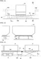
- a trailer for aviation container transportation (trailer hereinafter) 10 has a front end connected to a connecting part 12A of an upper portion of a rear wheel of a tractor 12, and is pulled by the tractor 12 to travel.
- Reference number 70 to the right side of FIGS. 3 and 4 denotes a container loading and unloading device (in this embodiment 1, a cart or dolly loading and unloading an air container 14) for loading and unloading the air container 14 to and from the aircraft.
- a container loading and unloading device in this embodiment 1, a cart or dolly loading and unloading an air container 14 for loading and unloading the air container 14 to and from the aircraft.
- the trailer 10 includes a horizontal container deck 20 on which four air containers 14 can be placed, and a lashing device 30 (further details are described later) for fixing the air container 14 placed on the container deck 20.
- the container deck 20 is composed of a central elevating floor 40 provided in the vehicle front-rear direction intermediate portion, a rear elevating floor 60 provided as an extended floor and gate floor in the rear end portion of the vehicle body, a front mounting floor 50A of the vehicle body front side of the central elevating floor 40, and a rear mounting floor 50B, rear side of the central elevating floor 40.
- a horizontal roller conveyor 44 and a ball roller conveyor 64 which will be described later, in the center elevation floor 40 and the rear elevating floor 60 are collectively referred to as "roller conveyor”.
- FIG. 6 is a rear view of the trailer 10.
- the air container 14 has a rectangular top panel 14A thereof, the container deck 20, in a posture in which a rectangular side of the top panel 14A in a plan view is a trailer front-rear direction in a side-by-side arrangement of the air container 14 in the vehicle body front-rear direction, a latching hook 30A of the lashing device 30 in this state (see FIGS. 16 to 17 ; described later in detail) is adapted to be lashed by.
- the front mounting floor 50A and the central elevating floor 40 has respectively a length that can amount one air container 14, the rear mounting floor 50B has a length that can amount two air containers 14, the long side of the top panel 14A respectively in a posture that the vehicle body front-rear direction, and a length that can be placed.
- the front mounting floor 50A and the rear mounting floor 50B is provided horizontally at a position higher than a wheel house 16A of a rear wheel 16 of the trailer 10, and, as shown in FIGS. 8 to 10 , respectively, a plurality of horizontal rollers 52A rotatably supported in the horizontal axis of the trailer width direction side by side in the trailer front-rear direction, constitute a fixed roller conveyor 52 for movably placing the air container 14 in the trailer front-rear direction.
- the central elevating floor 40 is provided at a position adjoining the front side of the wheel house 16A of the rear wheel 16, and as shown in FIGS. 11 and 12 , the height of the fixed roller conveyor 52 is defined as an upper limit height of the elevating floor H m a x , and the height at which the air container 14 can be transferred to and from the container loading/unloading device 70 is defined as a lower limit height H m i n of the elevating floor, between which it can be lifted and lowered by a center electric table lifter 46 including an X-link 46A.
- the central elevating floor 40 has a horizontal roller conveyor 44 integrally fixed to the upper surface of the central turntable 43, and one of the air containers 14 mounted on the horizontal roller conveyor 44 is rotatable in the horizontal plane at a position between the upper limit height H m a x of the elevating floor and the lower limit height H m i n of the elevating floor.
- a total of four outriggers 11 are attached to both outer sides in the vehicle body widthwise directions at positions in contact with the front side of the connecting part 12A of the trailer vehicle body and positions in contact with the rear side of the rear wheels 16, respectively, so that the change in vehicle height and tilt of the trailer 10 are suppressed, and the lower limit height H m i n of the elevating floor becomes constant.
- the outrigger 11 is configured so that the height of the trailer body can be adjusted so that the upper surfaces of the horizontal roller conveyor 44 on the central elevating floor 40 and the ball roller conveyor 64 (described in detail below) on the rear elevating floor 60, which are H m i n the lower limit height of the elevating floor, are 1 to 3cm lower than the load height H u n l o of the air container loading/unloading device when the air container is unloaded, and the upper surface of the ball conveyor 44, which is H m i n the lower limit height of the elevating floor, is 1 to 3cm higher than the load height H l o of the container loading/unloading device when the container is unloaded.
- the central elevating floor 40 is a configuration in which the whole is rotated in a horizontal plane integrally with the central turntable 43, in a plan view in a posture during trailer running, being a long rectangular in the front-rear direction of the vehicle body, having an arc-shaped leading edge 40A which is convex in the front and an arc-shaped trailing edge 40B which is convex in the rear.
- Arc radius of the arc-shaped leading edge 40A and the arc-shaped trailing edge 40B is adapted to coincide with the rotation locus of the outer peripheral portion when the central elevating floor 40 is rotated by the central turntable 43.
- the central elevating floor 40 is integrally provided with a pair of central movable side guides 41 in the short side direction of the cross-sectional U-shaped to engage with the container sliding part 14B slidably in the long side direction. Furthermore, in order to prevent the overrun of the air container 14 transferred to the central elevating floor 40 guided by the central movable side guide 41, a central stopper 42A is provided which is driven to a position to be a stopper in contact with the air container 14, or a retracted position without interference with the air container 14.
- Central movable side guide 41 is configured to be integrally rotated with the central turntable 43, and the posture of aligning the vehicle body front-rear direction with respect to a fixed side guide 80, or a posture perpendicular to the fixed side guide 80.
- the central elevating floor 40 includes a horizontal roller conveyor 44 for movably placing the air container 14 in the front-rear direction, the central movable side guide 41 in a state of being aligned in the vehicle body front-rear direction with respect to the fixed side guide 80.
- the horizontal roller conveyor 44 is composed of a plurality of horizontal rollers 44A rotatably supported in the horizontal axis of the trailer width direction by arranging in the trailer front-rear direction.
- the rear elevating floor 60 is configured to form a horizontal expanding floor capable of placing a single air container 14 at the same height as the container deck 20 in succession further rearward from the rear end of the container deck 20 during container loading and unloading, and to form a gate floor at the trailer rear end which rises at a right angle from a horizontal state and closes the trailer rear end, as shown in FIG. 2 , about the rear end of the container deck 20.
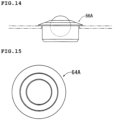
- the rear elevating floor 60 includes a ball roller conveyor 64 on an upper end surface including a rear turntable 63.
- the ball roller conveyor 64 as shown in FIGS.14 and 15 , constituted by arranging a plurality of ball units 64A facing upward with a rotatable ball. Then the air container 14, freely movably placed on the ball roller conveyor in an arbitrary direction in a horizontal plane, and from any of the left and right sides of the trailer vehicle body, and it is configured to be able to load and unload the air container 14.
- the ball roller conveyor 64 of the rear elevating floor 60 is capable of loading and unloading the air container 14 in the posture, the long side of the top panel 14A is in the vehicle body width direction, and the stacked air container 14 is a long side of the top panel 14A in a horizontal plane is configured to be rotated in a horizontal plane to the posture of the vehicle body front-rear direction, also, it is possible to load and unload the air container 14 from the vehicle body rear direction.
- the central elevating floor 40 and the rear elevating floor 60 further include a central electric table lifter 46 and a rear electric table lifter 66 with X links 46A and 66A, respectively.
- Air container 14 has a long sliding part 14B in the vehicle body front-rear direction on both sides in the body width direction of the bottom side (see the FIG. 7 ).
- a rear movable side guide 61 of the cross section is U-shaped is provided.
- the rear movable side guide 61 includes a front-rear direction guide 61A which is arranged in alignment thereto on the extension line of the vehicle body front-rear direction of the fixed side guide 80, and a lateral guide 61B for guiding the air container 14 on the lateral direction of the vehicle body which is arranged perpendicular to the front-rear direction guide 61A.
- the diameter of the rear turntable 63 in the rear elevating floor 60 is smaller than the width between, each pair of the front-rear direction guides 61A and 61A, and between the lateral guides 61B and 61B, together with these are arranged to pass through the vehicle body width direction both outside of the central turntable 43, when loading and unloading air containers, as shown by the two-dot chain line in FIG. 19 , it is configured to wait in a retracted position that does not interfere with the air container 14.
- the front-rear direction guide 61A As shown in FIG. 23 , in the rear elevating floor 60, the front-rear direction guide 61A, a rear movable side guide driving device 61C for driving the lateral guide 61B to the operating position or retracted position, the rear stopper 62A for preventing excessive passes of the placed air container 14, and a rear stopper driving device 62B for driving it to the stop position or retracted position.
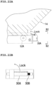
- Lashing device 30 in the front mounting floor 50A and the rear mounting floor 50B, the air container 14, in a state in which the sliding part 14B is restrained in the body width direction by the fixed side guide 80, FIG. 21A, FIG. 21B , FIG. 22A , as shown in FIG. 22B , the top panel shorter side perpendicular to the top panel long side direction end of the left and right sliding part 14B parallel, and a latching hook 30A to be latched/unlocked to the front and rear end latching portion 14C of the air container 14.
- the lashing device 30 is configured to be able to lash the air container 14 placed on the central elevating floor 40 at the center elevation floor upper limit height H m a x position and the center elevation floor lower limit height H m i n position, and the trailer 10 is able to run even when the air container 14 is lashed on the center elevation floor 40 at the center elevation floor lower limit height H m i n position.
- Reference numeral 30B in FIG. 21B denotes a compressedcoil spring that biases the latching hook 30A so that the state shown in FIG. 21A is maintained at the time of lashing (at the time of Lock) of the air container 14.
- FIG. 22A FIG. 22B
- FIG. 22B When unlocked, as shown in FIG. 22A, FIG. 22B , by compressing the compression coil spring 30B by the latching hook driving device 30C, and to maintain the latching hook 30A in the disengaged state.
- FIG. 23 is a block diagram showing a control unit 90 for controlling a drive device, a motor, the cylinder or the like, in this embodiment 1, the control unit 90 includes a drive unit 92, a control unit 94 and a remote controller 96.
- Drive unit 92 includes an outrigger driving cylinder 11A for driving the outrigger 11, a rear elevation floor open/close cylinder 60A for driving the rear elevating floor 60 vertically rises to constitute a rear gate or constitutes an extended floor in a horizontal, a rear movable side guide driving device 61C for driving the rear movable side guide 61, a central stopper driving device 42B for driving the central stopper 42A, a rear stopper driving device 62B for driving the rear stopper 62A, a latching hook driving device 30C for driving the latching hook 30A in the lashing device 30, a central electric table lifter driving motor 47 for driving the central electronic table lifter 46, a rear table lifter drive motor 67 for driving the rear electric table lifter 66, and a central turntable drive motor 43A for driving the central turntable 43, and a rear turntable drive motor 63A for driving the rear turntable 63.
- an outrigger driving cylinder 11A for driving the outrigger 11
- the control unit 94 based on an instruction signal input from the remote controller 96 is intended to control the driving device and the cylinder or motor of the drive unit 92.
- loading and unloading both simultaneously or only one of the loading and unloading to the trailer 10 in the central elevating floor 40 and the rear elevating floor 60 may be loaded and unloaded from both, unloaded from only one, or vice versa.
- the outrigger 11 is extended using an outrigger drive cylinder 11A. At this time, adjust so that the upper surface of the ball conveyor 44 is 1 to 3cm lower than the stackable height, and fix the length (height) of the outrigger 11.
- the height of the central elevating floor 40 is lowered to H m i n of the lower limit height of the elevating floor (hereinafter referred to as the lower limit height), and further rotated by 90 degrees from the state of FIG. 2 to the state of FIG. 5 by the central turntable 43, the posture for receiving the air container 14 from the vehicle body lateral direction.
- the air container 14 is transferred from the lateral direction of the vehicle body onto the horizontal roller conveyor 44, and the central elevating floor 40 is raised to the elevation floor upper limit height H m a x by the central electric table lifter 46 while the attitude of the air container 14 remains unchanged.
- the central turntable 43 is then driven by a central turntable drive motor 43A to rotate the air container 14 by 90° to align it with the fixed side guide 80 (see FIG. 2 ).
- the second air container 14 is also fixed on the central elevating floor 40 in the same manner as described above.
- the central elevating floor 40 is fixed to the upper limit height position. Incidentally, by lowering the center of gravity of the trailer, in order to improve the running stability, in a state of placing the air container 14, it is also possible to fix the central elevating floor 40 to the lower limit height position.
- the outrigger 11 is extended using an outrigger drive cylinder 11A. At this time, adjust so that the upper surface of the ball conveyor 44 is 1 to 3cm higher than the stackable height to fix the height of the outrigger 11.
- the lashing device 30 is disengaged, and the air container 14 is extruded laterally, followed by the air container 14 on the front mounting floor 50A to disengage the lashing device 30 and move it onto the central elevating floor 40.
- the central turntable 43 rotates the air container 14 by 90 ° to the vehicle body lateral direction, and then fed from the central elevating floor 40.
- the central elevating floor 40 is fixed to the upper limit height position or the lower limit height position, and the container loading and unloading by the rear elevating floor 60 is confirmed to be completed, the outrigger 11 is pulled up to finish the unloading.
- the rear elevating floor 60 is opened rearward by the rear elevating floor open/close cylinder 60A to form a horizontal extended floor as shown in FIGS. 3 and 4 .
- the outrigger 11 is extended. At this time, adjust the height of the outrigger 11 so that it is 1 to 3cm lower than the height that can be loaded and unloaded on the upper surface of the ball conveyor 44, and fix it.
- the rear elevating floor 60 is set to the lower limit height H m i n of the elevating floor, the condition shown in FIG. 3 is set, and further, the rear movable side guides 61 are set to the attitude of receiving the air container 14 from the lateral direction of the vehicle body or from the rear direction.
- the rear stopper 62A of the rear elevating floor 60 is made to protrude from the upper surface of the ball conveyor 44, and is set to a stopper state abutting the tip of the air container 14 which is transferred.
- the air container 14 is loaded from the vehicle body lateral direction and guided by the lateral guide 61B on the ball conveyor 44, when loading from the rear, the front-rear direction guide 61A as a guide.
- the rear elevating floor 60 is raised to the elevating floor upper limit height H m a x while the attitude of the air containers 14 remains unchanged.
- the rear turntable 63 rotates the air container 14 laterally loaded on the vehicle body by 90°, or the air container 14 loaded from the rear of the vehicle body is not rotated, the front-rear direction guide 61A is left as it is, to align the air container 14 to the fixed side guide 80.
- the air container 14 is transferred to the fixed roller conveyor 52 of the rear mounting floor 50B by the fixed side guide 80 as a guide, and is moved to the front end of the rear mounting floor 50B, where, the lashing device 30, to secure the air container 14.
- the second air container 14 is loaded from the rear elevating floor 60 and transferred to the rear side of the first loaded air container 14 of the rear mounting floor 50B, secured by lashing device 30.
- the rear elevating floor 60 is vertically raised by the rear elevating floor open/close cylinder 60A to close the rear end of the tractor as a rear gate, and after confirming completion of loading of the air container 14 by the central elevating floor 40, the outrigger 11 is pulled up to make the trailer for aviation container transportation 10 capable of traveling.
- the rear elevating floor 60 is opened rearward to form a horizontal extended floor by the rear elevating floor open/close cylinder 60A as shown in FIG. 3 , and the outrigger 11 is extended by the outrigger driving cylinder 11A.
- the upper surface of the ball conveyor 44 is fixed by adjusting the height of the outrigger 11 so as to be 1 to 3cm higher than the loading and unloading possible height.
- the rear elevating floor 60 is set to the rear elevating floor upper limit height H m a x by the rear electric table lifter 66, and then the front-rear direction guide 61A is made to protrude from the retracted position by the rear movable side guide drive 61C to align with the fixed side guide 80, the lashing device 30 of the rearmost (first) air container 14 is released, and the air container 14 is guided from the rear mounting floor 50B by the front-rear direction guide 61A to move onto the ball conveyor 44.
- Air container 14 or a state capable of being fed in the rear direction as it is by the front-rear direction guide 61A, or, after the front-rear direction guide 61A to the retracted position by the rear movable side guide drive unit 61C, by the rear turntable 63, the air container 14 by 90 ° rotated to enable delivery in the lateral direction, then, as a guide, the rear movable side guide 61, to transfer the air container 14 to the unloading yard or the like.
- the trailer for aviation container transportation 10 includes two elevating floors, namely, the central elevating floor 40 and the rear elevating floor 60, and can be quickly loaded or unloaded from both or one of them.
- the present invention is not limited to the above, and the trailer for aviation container transportation may be provided only with the central elevating floor 40 and not with the rear elevating floor 60, and may be provided only with the rear elevating floor 60 without the central elevating floor 40.
- each of the central elevating floor 40 and the rear elevating floor 60 has a configuration using an electric table lifter having an X link, the present invention is not limited thereto, it may be configured to be raised and lowered by a chain of the motor drive.
- the central elevating floor 40 is configured to rotate integrally with the turntable may be configured to use a ball roller conveyor as well as the rear elevating floor 60. In this case, it is not necessary to return the movable side guide to the retracted position.
Landscapes
- Engineering & Computer Science (AREA)
- Mechanical Engineering (AREA)
- Transportation (AREA)
- Aviation & Aerospace Engineering (AREA)
- Chemical & Material Sciences (AREA)
- Combustion & Propulsion (AREA)
- Auxiliary Methods And Devices For Loading And Unloading (AREA)
- Loading Or Unloading Of Vehicles (AREA)
Claims (14)
- Remorque (10) pour le transport de conteneurs d'aviation, dotée d'un plateau de conteneur horizontal (20) sur lequel plusieurs conteneurs aérien (14) peuvent être placés en rangée dans la direction avant-arrière, et d'un dispositif d'arrimage (30) pour fixer le conteneur aérien (14) placé sur le plateau de conteneur (20),dans lequel le plateau de conteneur (20) est pourvu avec un plancher élévateur horizontal (40) et un plancher de montage horizontal (50A, 50B), le plancher élévateur horizontal (40) se trouve sur au moins une de la partie intermédiaire avant-arrière de corps de véhicule et la partie arrière de corps de véhicule, le plancher de montage horizontal (50A, 50B) est adjacent au plancher élévateur (40) et fixé sur la direction verticale de corps de véhicule,le plancher de montage (50A, 50B) comprend un convoyeur à rouleaux (52) et une paire de guides latéraux fixes (80), le convoyeur à rouleaux (52) est disposé horizontalement à une position plus élevée que le passage de roue (16A) de la roue arrière (16), et une pluralité de rouleaux horizontaux (52A) supportés de manière rotative dans l'axe horizontal de la direction de largeur de remorque sont disposés dans la direction avant-arrière de remorque, le convoyeur à rouleaux (52) pour placer de manière mobile le conteneur aérien (14) dans la direction avant-arrière, la paire de guides latéraux fixes (80) a la forme d'un U dans la section transversale de la direction de largeur de corps de véhicule, et lorsque le côté perpendiculaire au côté long du panneau supérieur (14A) du conteneur aérien (14) rectangulaire en vue de plan et le côté court, une partie coulissante de conteneur (14B) de la direction de côté court sur les deux côtés du côté inférieur du conteneur aérien (14) est engagée de manière coulissante dans la direction avant-arrière de corps de véhicule,le plancher élévateur (40) comprend un convoyeur à rouleaux (44), et est intégralement soulevable et abaissable avec le convoyeur à rouleaux (44) lorsque un conteneur aérien (14) est monté horizontalement avec la hauteur de la surface supérieure du convoyeur à rouleaux (44) sur le plancher de montage (50A, 50B) étant la hauteur limite supérieure du plancher élévateur (40) et la hauteur du conteneur aérien (14) par rapport au dispositif de chargement et de déchargement de conteneur, et une position plus basse que le passage de roue (16A) de la roue arrière (16) étant la hauteur limite inférieure du plancher élévateur (40),le panneau supérieur (14A) du conteneur aérien (14) est rectangulaire, et dans lequel le plateau de conteneur (20) est conçu pour placer le conteneur aérien (14) dans une position dans laquelle un côté rectangulaire du panneau supérieur (14A) se trouve dans une direction avant-arrière de remorque dans une vue de plan,caractérisé par le fait quele plancher élévateur horizontal (40) est capable de charger et décharger le conteneur aérien (14) à partir de n'importe quel côté gauche ou droit de corps de véhicule de remorque (10),le plancher élévateur (40) comprend un plateau tournant (43) et est intégralement soulevable et abaissable avec le plateau tournant (43) et le convoyeur à rouleaux (44),le plateau tournant (43), placé un seul conteneur aérien (14), est rotatif dans un plan horizontal, etle plancher élévateur (40), pendant chargement et déchargement de conteneur, continue vers l'arrière à partir de l'extrémité arrière du plateau de conteneur (20) à la même hauteur que le plateau de conteneur (20), pour former un plancher d'expansion horizontal capable de placer un conteneur aérien (14), pendant le déplacement de la remorque, l'extrémité arrière de remorque s'élevant à partir d'un état horizontal à un angle droit pour former un plancher de porte pour fermer l'extrémité arrière de remorque est formée sur l'extrémité arrière de remorque, le plancher élévateur arrière (60) de l'état horizontal a été rendu possible pour charger et décharger le conteneur aérien (14) horizontalement, même à partir de l'extrémité arrière.
- Remorque (10) pour le transport de conteneurs d'aviation selon la revendication 1, le plancher élévateur (40) est une configuration dans laquelle l'ensemble est tourné dans un plan horizontal intégralement avec le plateau tournant (43), dans une vue de plan dans une position dans laquelle la remorque (10) se déplace, le bord d'attaque en forme d'arc (40A) et le bord de fuite en forme d'arc (40B) convexe vers l'arrière, le rayon du bord d'attaque en forme d'arc (40A) et du bord de fuite en forme d'arc (40B) est conçu pour coïncider avec le lieu de rotation de la partie périphérique extérieure devant être mise en rotation par le plateau tournant (43), la partie coulissante du conteneur (14B) est une paire de guides latéraux de plancher élévateur (41A) de la forme de U en section transversale, le guide latéral de plancher élévateur (41) est intégralement tourné avec le guide latéral fixe (41A), ou conçu pour être dans une attitude perpendiculaire au guide latéral fixe (41A).
- Remorque (10) pour le transport de conteneurs d'aviation selon les revendications 1 ou 2,
le plancher élévateur (40), la partie coulissante de conteneur (14B) est formée en fournissant une paire de guides latéraux de plancher élévateur (41B) dans la direction du côté court de la forme de U en section transversale pour s'engager de manière coulissante dans la direction de côté long, le guide latéral de plancher élévateur (41A) est configuré pour être aligné dans la direction avant-arrière de corps de véhicule par rapport au guide latéral fixe (41). - Remorque (10) pour le transport de conteneurs d'aviation selon l'une des revendications 1 à 3,le plancher élévateur comprend un plancher élévateur central (40) situé à une position adjacente au côté avant de la roue arrière (16),le plancher élévateur central (40) comprend un plateau tournant (43) et un convoyeur à rouleaux (44), la hauteur de la surface supérieure du convoyeur à rouleaux (44) dans le plancher de montage (50) étant une hauteur limite supérieure de plancher élévateur central, une position plus basse que le passage de roue (16A) de la roue arrière (16) étant une hauteur limite inférieure de plancher élévateur central, lorsque l'un des conteneurs aériens (14) est placé horizontalement, le plateau tournant (43) et le convoyeur à rouleaux (44) peuvent être intégralement soulevés,le plancher de montage (50) comprend le plancher de montage avant (50A) et le plancher de montage arrière (50B) du plancher élévateur central (40),le plancher de montage avant (50A) peut accueillir au moins un conteneur aérien (14), le plancher de montage arrière (50B) peut accueillir au moins deux conteneurs aériens (14).
- Remorque (10) pour le transport de conteneurs d'aviation selon la revendication 1,le plancher élévateur (40, 60) se compose d'un plancher élévateur central (40) et d'un plancher élévateur arrière (60), le plancher élévateur central (40) se trouve sur la partie intermédiaire avant-arrière de corps de véhicule et le plancher élévateur arrière (60) sur la partie arrière de corps de véhicule, le plancher de montage (50) est adjacent à l'extrémité avant du plancher élévateur central (40) et est disposé entre le plancher élévateur central (40) et le plancher élévateur arrière (60), le plancher de montage (50) se compose d'un plancher de montage avant (50A) et le plancher de montage arrière (50B) du côté avant et du côté arrière du plancher élévateur central (40), le plancher de montage avant (50A) est capable de placer au moins un conteneur aérien (14), le plancher de montage arrière (50A) est capable de placer au moins deux conteneurs aérien (14), respectivement,le plancher élévateur arrière (60) est configuré pour former un plancher d'expansion horizontal sur lequel un conteneur aérien (14) peut être placé à la même hauteur que le plateau de conteneur (20) en succession plus loin vers l'arrière de l'extrémité arrière du plateau de conteneur (20) au moment du chargement/déchargement de conteneur, et de former un plancher de porte à l'extrémité arrière du plateau de conteneur (20) qui s'élève à angle droit à partir d'un état horizontal et ferme l'extrémité arrière de la remorque à angle droit autour de l'extrémité arrière du plateau de conteneur (20) lorsque la remorque (10) est en marche, et le plancher élévateur arrière (60) à l'état horizontal est configuré pour charger/décharger le conteneur aérien (14) horizontalement, même à partir de l'extrémité arrière.
- Remorque (10) pour le transport de conteneurs d'aviation selon les revendications 4 ou 5,le plancher élévateur central (40) est une configuration dans laquelle l'ensemble est tourné dans un plan horizontal en même temps qu'un plateau tournant central (43), dans une vue de plan dans une position pendant déplacement de la remorque, un bord d'attaque en forme d'arc (40A) et un bord de fuite en forme d'arc convexe vers l'arrière (40B), le rayon du bord d'attaque en forme d'arc (40A) et du bord de fuite en forme d'arc sont conçus pour coïncider avec le lieu de rotation de la partie périphérique extérieure qui est tournée par le plateau tournant central (43),la partie coulissante de conteneur (14B) est une paire de guides latéraux de plancher élévateur en forme de U en section tranversale, le guide latéral de plancher élévateur (41A) est intégralement tourné avec le plateau tournant (43), et dans une attitude d'alignement dans la direction avant-arrière de corps de véhicule par rapport au guide latéral fixe (80), ou dans une attitude perpendiculaire au guide latéral fixe (80).
- Remorque (10) pour le transport de conteneurs d'aviation selon la revendication 6,
le convoyeur à rouleaux (44) du plancher élévateur central (40) est un rouleau horizontal de convoyeur à rouleaux horizontal (44A) qui monte de manière mobile le conteneur aérien (14) dans une direction avant-arrière, dans lequel une pluralité de rouleaux horizontaux (44A) supportés de manière rotative dans un axe horizontal dans une direction de largeur de remorque sont disposés dans une direction avant-arrière de remorque lorsque le guide latéral du plancher élévateur (41A) est aligné dans une direction avant-arrière de corps de véhicule par rapport au guide latéral fixe (80). - Remorque (10) pour le transport de conteneurs d'aviation selon l'une quelconque des revendications précédentes,
dans le plancher élévateur arrière (60), le convoyeur à rouleaux est un convoyeur à rouleaux à billes (64), qui se trouve sur la surface supérieure du plancher élévateur arrière (60) comprenant le plateau tournant (63), configuré en disposant une pluralité d'unités à billes ascendantes (64A) ayant une bille rotative à une extrémité supérieure pour placer de manière mobile le conteneur aérien (14) dans une direction arbitraire dans un plan horizontal. - Remorque (10) pour le transport de conteneurs d'aviation selon l'une quelconque des revendications 5 à 7,
le dispositif d'arrimage (30) est configuré pour arrimer un conteneur aérien (14) placé sur le plancher élévateur central (40) à la position de hauteur limite inférieure du plancher élévateur central (40), et la remorque (10) pour le transport de conteneurs aériens est capable de se déplacer lorsque le conteneur aérien (14) est arrimé sur le plancher élévateur central (40) à la position de hauteur limite inférieure du plancher élévateur central (40). - Remorque (10) pour conteneur d'aviation selon l'une des revendications 4 à 7 ou 9,le plancher élévateur central (40) comporte une paire de guides latéraux de plancher élévateur (41B) dans la direction de largeur de corps de véhicule de la forme de U en section transversale, dans laquelle la direction de largeur de corps de véhicule des deux côtés du côté inférieur du conteneur aérien (14) est engagée de manière coulissante avec la paire de guides latéraux de plancher élévateur (41) dans la direction avant-arrière de corps de véhicule, la section transversale comporte une paire de guides latéraux de plancher élévateur (41B) dans la direction de largeur de corps de véhicule de la forme de U,le guide latéral de plancher élévateur (41) est disposé sur les deux côtés extérieurs dans la direction de largeur de corps de véhicule du plateau tournant (43) dans le plancher élévateur central (40), lors du chargement et du déchargement du conteneur aérien (14) depuis l'extérieur dans la direction de largeur de corps de véhicule, les guides latéraux de plancher élévateur (41) sont configurés pour attendre dans une position rétractée qui n'interfère pas avec le conteneur aérien (14).
- Remorque (10) pour le transport de conteneurs d'aviation selon l'une quelconque des revendications 6, 7 et 10,
le guide latéral de plancher élévateur (41) est intégralement supporté par un plateau tournant (43) et est configuré pour tourner de manière synchrone. - Remorque (10) pour le transport de conteneurs d'aviation selon la revendication 11,les guides latéraux de plancher élévateur (41), lorsque le conteneur aérien (14) est chargé depuis la direction latérale du corps de conteneur, dans la direction de largeur de corps de véhicule, et de manière à ce que la position soit perpendiculaire à la ligne d'extension du guide latéral fixe,le plancher élévateur central (40) est guidé par les guides latéraux de plancher élévateur (41) et pourvu d'une butée qui s'appuie contre l'extrémité du conteneur aérien (14) pour limiter le mouvement dans la direction de largeur de corps de conteneur lors du chargement du conteneur aérien (14) dans la direction de largeur de corps de conteneur.
- Remorque (10) pour le transport de conteneurs d'aviation selon l'une quelconque des revendications précédentes,le plancher élévateur arrière (60) comporte une paire de guides latéraux de plancher élévateur arrière (61A) dans la direction de largeur de corps de véhicule de la forme de U en section transversale, dans laquelle, la direction de largeur de corps de véhicule des deux côtés de la face inférieure du conteneur aérien (14) est engagée de manière coulissante avec la paire de guides latéraux de plancher élévateur (61A) dans la direction avant-arrière de corps de véhicule, la section transversale comporte une paire de guides latéraux de plancher élévateur arrière (61A) dans la direction de largeur de corps de véhicule de la forme de U,les guides latéraux du plancher élévateur arrière (61A) sont intégralement supportés par le plateau tournant (63) et sont configurés pour tourner en synchronisation avec le plateau tournant (63) et pour être dans une position qui s'aligne par rapport au guide latéral fixe (80) dans la direction avant-arrière de corps de véhicule ou dans une position qui est perpendiculaire à une ligne d'extension du guide latéral fixe (80).
- Remorque (10) pour le transport de conteneurs d'aviation selon l'une des revendications 1 à 13,
sur chacun des côtés gauche et droit du corps de remorque, à la position arrière de la roue arrière (16) et à l'extrémité avant du corps de remorque un total de quatre stabilisateurs (11) prévus à l'extrémité avant du corps de remorque, le stabilisateur (16) est configuré pour ajuster la hauteur du corps de remorque de sorte que la surface supérieure du convoyeur à rouleaux (44) du plancher élévateur (40) à la hauteur inférieure de plancher élévateur soit inférieure de 1 à 3 cm à la hauteur de déchargement Hunlo du dispositif de chargement/déchargement de conteneur lorsqu'un conteneur aérien (14) est chargé, et la surface supérieure du convoyeur à rouleaux (44) à la hauteur inférieure de plancher élévateur est de 1 à 3 cm plus haute que la hauteur de chargement Hlo du dispositif de chargement/déchargement de conteneur lors qu'un conteneur aérien (14) est déchargé.
Applications Claiming Priority (2)
| Application Number | Priority Date | Filing Date | Title |
|---|---|---|---|
| JP2020033233A JP6807617B1 (ja) | 2020-02-28 | 2020-02-28 | 航空コンテナ輸送用トレーラ |
| PCT/JP2021/006899 WO2021172367A1 (fr) | 2020-02-28 | 2021-02-24 | Remorque pour le transport de conteneurs d'aviation |
Publications (4)
| Publication Number | Publication Date |
|---|---|
| EP3950422A1 EP3950422A1 (fr) | 2022-02-09 |
| EP3950422A4 EP3950422A4 (fr) | 2023-01-11 |
| EP3950422B1 true EP3950422B1 (fr) | 2024-08-14 |
| EP3950422B8 EP3950422B8 (fr) | 2024-09-25 |
Family
ID=73992928
Family Applications (1)
| Application Number | Title | Priority Date | Filing Date |
|---|---|---|---|
| EP21761858.6A Active EP3950422B8 (fr) | 2020-02-28 | 2021-02-24 | Remorque pour le transport de conteneurs d'aviation |
Country Status (4)
| Country | Link |
|---|---|
| US (1) | US12017571B2 (fr) |
| EP (1) | EP3950422B8 (fr) |
| JP (1) | JP6807617B1 (fr) |
| WO (1) | WO2021172367A1 (fr) |
Families Citing this family (10)
| Publication number | Priority date | Publication date | Assignee | Title |
|---|---|---|---|---|
| US11572238B2 (en) * | 2019-10-01 | 2023-02-07 | Oceaneering International, Inc. | Autonomous loading/unloading of cargo |
| CN113212788B (zh) * | 2021-04-29 | 2022-03-04 | 腾达航勤设备(无锡)有限公司 | 一种电动式集装货物装载机 |
| KR102338776B1 (ko) | 2021-06-01 | 2021-12-15 | (주)미도지리정보 | 유사촬영이미지 합성을 위한 항공촬영 영상처리 시스템 |
| KR102341610B1 (ko) | 2021-06-01 | 2021-12-22 | (주)미도지리정보 | 지피에스를 기반으로 촬영된 영상이미지를 처리하는 영상처리시스템 |
| CN113443164B (zh) * | 2021-06-15 | 2024-03-15 | 漳州必佳自动化设备有限公司 | 一种uld输送平台 |
| US11685301B2 (en) * | 2021-10-19 | 2023-06-27 | Harbinger Motors Inc. | Cargo containers and methods of using thereof for deliveries using multiple different types of trucks |
| EP4201738A1 (fr) * | 2021-12-21 | 2023-06-28 | Beijing Tusen Zhitu Technology Co., Ltd. | Fixation automatique de contenant sur remorque |
| US11975647B2 (en) * | 2022-02-17 | 2024-05-07 | Ford Global Technologies, Llc | Vehicle including lift assembly |
| CN115230982A (zh) * | 2022-07-08 | 2022-10-25 | 南京航空航天大学 | 一种具有升降功能的大质量固定翼无人机机身储运装置 |
| JP7330409B1 (ja) | 2023-04-06 | 2023-08-21 | 全日本空輸株式会社 | ドーリシステム |
Family Cites Families (19)
| Publication number | Priority date | Publication date | Assignee | Title |
|---|---|---|---|---|
| US3207087A (en) * | 1962-12-19 | 1965-09-21 | Clifford S Goby | Railway car having a vertically movable load support platform |
| US3561625A (en) * | 1969-05-13 | 1971-02-09 | Tridair Industries | Trailers with power transfer system |
| JPS51151918A (en) | 1975-06-18 | 1976-12-27 | Suehiro Sharyo Seisakusho:Kk | Cargo-working method and equipment |
| JPS60203541A (ja) | 1984-03-27 | 1985-10-15 | Nikko Sangyo Kk | カ−ゴロ−ダ− |
| IT1177858B (it) | 1984-07-02 | 1987-08-26 | Airport Ground Equipment Itali | Carrello con piattaforma girevole i donea all'accostamento con comprenetrazione di mezzi intermedi di trasporto,per il trasferimento automatico di unita' di carico per aeromobili |
| NL8502471A (nl) | 1985-09-10 | 1987-04-01 | Talson Transport Engineering | Vrachtvoertuig, in het bijzonder van het type oplegger, met een aan de voorzijde verhoogde laadvloer. |
| JPS6397445A (ja) | 1986-10-13 | 1988-04-28 | Suehiro Sharyo Seisakusho:Kk | トレ−ラ− |
| US5246241A (en) * | 1992-04-23 | 1993-09-21 | Baver Bruce W | Adjustable deck trailer apparatus |
| US5378105A (en) * | 1992-11-02 | 1995-01-03 | Palko; Richard L. | Cargo handling system |
| US5467827A (en) * | 1993-09-20 | 1995-11-21 | Mcloughlin; John E. | Modular fire truck |
| DE9400489U1 (de) * | 1994-01-13 | 1994-03-03 | Hoffmann, Heinz-Rainer, Dr.-Ing., 37632 Eschershausen | Tieflader |
| EP0698525B1 (fr) * | 1994-08-23 | 1999-06-02 | Shinko Electric Co. Ltd. | Système de manipulation pour conteneurs |
| DE19542816C2 (de) * | 1995-11-16 | 2001-03-01 | Scherer Rosmarie | Transportfahrzeug |
| US7665788B2 (en) * | 2003-02-15 | 2010-02-23 | Middlegate Marketing Ltd. | Vehicles and trailers incorporating moveable load carrying platforms |
| EP1741594B2 (fr) | 2005-07-07 | 2014-11-26 | Omar-S.R.L. | Dispositif et méthode pour le mouvement de palettes |
| US8313278B2 (en) * | 2007-03-01 | 2012-11-20 | The Boeing Company | Modular interchangeable cargo deck |
| DE202007009734U1 (de) | 2007-07-12 | 2007-09-27 | Aehling, Christoph | Transportfahrzeug mit einem Laderaum |
| JP6401685B2 (ja) | 2015-10-01 | 2018-10-10 | 東芝三菱電機産業システム株式会社 | 荷台装置 |
| US20190351801A1 (en) * | 2018-05-17 | 2019-11-21 | Remorques Marca Inc. | Trailer adapted to support various types of loading equipment and method of using the same |
-
2020
- 2020-02-28 JP JP2020033233A patent/JP6807617B1/ja active Active
-
2021
- 2021-02-24 EP EP21761858.6A patent/EP3950422B8/fr active Active
- 2021-02-24 WO PCT/JP2021/006899 patent/WO2021172367A1/fr not_active Ceased
- 2021-02-24 US US17/610,038 patent/US12017571B2/en active Active
Also Published As
| Publication number | Publication date |
|---|---|
| JP6807617B1 (ja) | 2021-01-06 |
| WO2021172367A1 (fr) | 2021-09-02 |
| EP3950422A1 (fr) | 2022-02-09 |
| EP3950422B8 (fr) | 2024-09-25 |
| US20220194627A1 (en) | 2022-06-23 |
| JP2021133865A (ja) | 2021-09-13 |
| US12017571B2 (en) | 2024-06-25 |
| EP3950422A4 (fr) | 2023-01-11 |
Similar Documents
| Publication | Publication Date | Title |
|---|---|---|
| EP3950422B1 (fr) | Remorque pour le transport de conteneurs d'aviation | |
| EP2200883B1 (fr) | Système de guidage sur système d'échange autoroutier | |
| US10583847B2 (en) | Raisable carrying device | |
| US10059450B2 (en) | Cargo handling system, method and apparatus | |
| US5630694A (en) | Integrated container handling system | |
| KR20230118462A (ko) | 드론이 도킹되는 화물 차량 및 이를 이용한 물류시스템 제어 방법 | |
| CN111573316B (zh) | 自动装卸车系统、自动装车方法及自动卸车方法 | |
| KR101549365B1 (ko) | 적재함의 내부화물 이동장치 | |
| CN105501461B (zh) | 半挂式机场升降装卸摆渡装置 | |
| HUT76963A (hu) | Eljárás és berendezés rakományok átrakodására | |
| CN108367699A (zh) | 车辆拖车系统 | |
| US10611288B2 (en) | Transport vehicle for containers | |
| JP3214130B2 (ja) | 牽引トレーラ付きコンテナパレットローダ | |
| WO2008030786A2 (fr) | Dispositif d'attache pour le déplacement de conteneurs de cargaison | |
| US20240190327A1 (en) | Logistics system | |
| CN110550412A (zh) | 智能驾驶运输工具、运输工具组合及控制方法 | |
| CN112654550A (zh) | 在铁路网上的装载系统和运输轮式车辆 | |
| CN215158533U (zh) | 智能驾驶运输工具、运输工具组合 | |
| EP0698525B1 (fr) | Système de manipulation pour conteneurs | |
| JP2001059357A (ja) | 車両方向転換装置及び機械式駐車装置 | |
| CN209797390U (zh) | 一种基于空轨城市值机的垂直装卸系统 | |
| CN220147456U (zh) | 一种货运高铁用的站台接驳转运车 | |
| JP3448037B2 (ja) | 平面往復式駐車装置 | |
| JP3888897B2 (ja) | 機械式駐車装置のピットの隙間塞ぎ装置 | |
| CN121317602A (zh) | 一种船舶行李转运系统及转运方法 |
Legal Events
| Date | Code | Title | Description |
|---|---|---|---|
| STAA | Information on the status of an ep patent application or granted ep patent |
Free format text: STATUS: THE INTERNATIONAL PUBLICATION HAS BEEN MADE |
|
| PUAI | Public reference made under article 153(3) epc to a published international application that has entered the european phase |
Free format text: ORIGINAL CODE: 0009012 |
|
| STAA | Information on the status of an ep patent application or granted ep patent |
Free format text: STATUS: REQUEST FOR EXAMINATION WAS MADE |
|
| 17P | Request for examination filed |
Effective date: 20211102 |
|
| AK | Designated contracting states |
Kind code of ref document: A1 Designated state(s): AL AT BE BG CH CY CZ DE DK EE ES FI FR GB GR HR HU IE IS IT LI LT LU LV MC MK MT NL NO PL PT RO RS SE SI SK SM TR |
|
| A4 | Supplementary search report drawn up and despatched |
Effective date: 20221209 |
|
| RIC1 | Information provided on ipc code assigned before grant |
Ipc: B62D 53/06 20060101ALI20221205BHEP Ipc: B60P 1/64 20060101ALI20221205BHEP Ipc: B60P 1/52 20060101ALI20221205BHEP Ipc: B64F 1/32 20060101ALI20221205BHEP Ipc: B62D 53/04 20060101ALI20221205BHEP Ipc: B60P 7/13 20060101ALI20221205BHEP Ipc: B60P 1/44 20060101ALI20221205BHEP Ipc: B60P 1/02 20060101ALI20221205BHEP Ipc: B60P 1/00 20060101AFI20221205BHEP |
|
| DAV | Request for validation of the european patent (deleted) | ||
| DAX | Request for extension of the european patent (deleted) | ||
| STAA | Information on the status of an ep patent application or granted ep patent |
Free format text: STATUS: EXAMINATION IS IN PROGRESS |
|
| 17Q | First examination report despatched |
Effective date: 20231002 |
|
| GRAP | Despatch of communication of intention to grant a patent |
Free format text: ORIGINAL CODE: EPIDOSNIGR1 |
|
| STAA | Information on the status of an ep patent application or granted ep patent |
Free format text: STATUS: GRANT OF PATENT IS INTENDED |
|
| INTG | Intention to grant announced |
Effective date: 20240312 |
|
| GRAS | Grant fee paid |
Free format text: ORIGINAL CODE: EPIDOSNIGR3 |
|
| GRAA | (expected) grant |
Free format text: ORIGINAL CODE: 0009210 |
|
| STAA | Information on the status of an ep patent application or granted ep patent |
Free format text: STATUS: THE PATENT HAS BEEN GRANTED |
|
| AK | Designated contracting states |
Kind code of ref document: B1 Designated state(s): AL AT BE BG CH CY CZ DE DK EE ES FI FR GB GR HR HU IE IS IT LI LT LU LV MC MK MT NL NO PL PT RO RS SE SI SK SM TR |
|
| REG | Reference to a national code |
Ref country code: GB Ref legal event code: FG4D |
|
| REG | Reference to a national code |
Ref country code: CH Ref legal event code: EP |
|
| REG | Reference to a national code |
Ref country code: DE Ref legal event code: R096 Ref document number: 602021017273 Country of ref document: DE |
|
| REG | Reference to a national code |
Ref country code: CH Ref legal event code: PK Free format text: BERICHTIGUNG B8 |
|
| RAP4 | Party data changed (patent owner data changed or rights of a patent transferred) |
Owner name: HAMANA WORKS CO., LTD. |
|
| REG | Reference to a national code |
Ref country code: IE Ref legal event code: FG4D |
|
| REG | Reference to a national code |
Ref country code: LT Ref legal event code: MG9D |
|
| REG | Reference to a national code |
Ref country code: NL Ref legal event code: MP Effective date: 20240814 |
|
| PG25 | Lapsed in a contracting state [announced via postgrant information from national office to epo] |
Ref country code: NO Free format text: LAPSE BECAUSE OF FAILURE TO SUBMIT A TRANSLATION OF THE DESCRIPTION OR TO PAY THE FEE WITHIN THE PRESCRIBED TIME-LIMIT Effective date: 20241114 |
|
| REG | Reference to a national code |
Ref country code: AT Ref legal event code: MK05 Ref document number: 1713002 Country of ref document: AT Kind code of ref document: T Effective date: 20240814 |
|
| PG25 | Lapsed in a contracting state [announced via postgrant information from national office to epo] |
Ref country code: FI Free format text: LAPSE BECAUSE OF FAILURE TO SUBMIT A TRANSLATION OF THE DESCRIPTION OR TO PAY THE FEE WITHIN THE PRESCRIBED TIME-LIMIT Effective date: 20240814 Ref country code: NL Free format text: LAPSE BECAUSE OF FAILURE TO SUBMIT A TRANSLATION OF THE DESCRIPTION OR TO PAY THE FEE WITHIN THE PRESCRIBED TIME-LIMIT Effective date: 20240814 Ref country code: PL Free format text: LAPSE BECAUSE OF FAILURE TO SUBMIT A TRANSLATION OF THE DESCRIPTION OR TO PAY THE FEE WITHIN THE PRESCRIBED TIME-LIMIT Effective date: 20240814 Ref country code: GR Free format text: LAPSE BECAUSE OF FAILURE TO SUBMIT A TRANSLATION OF THE DESCRIPTION OR TO PAY THE FEE WITHIN THE PRESCRIBED TIME-LIMIT Effective date: 20241115 Ref country code: PT Free format text: LAPSE BECAUSE OF FAILURE TO SUBMIT A TRANSLATION OF THE DESCRIPTION OR TO PAY THE FEE WITHIN THE PRESCRIBED TIME-LIMIT Effective date: 20241216 |
|
| PG25 | Lapsed in a contracting state [announced via postgrant information from national office to epo] |
Ref country code: BG Free format text: LAPSE BECAUSE OF FAILURE TO SUBMIT A TRANSLATION OF THE DESCRIPTION OR TO PAY THE FEE WITHIN THE PRESCRIBED TIME-LIMIT Effective date: 20240814 |
|
| PG25 | Lapsed in a contracting state [announced via postgrant information from national office to epo] |
Ref country code: LV Free format text: LAPSE BECAUSE OF FAILURE TO SUBMIT A TRANSLATION OF THE DESCRIPTION OR TO PAY THE FEE WITHIN THE PRESCRIBED TIME-LIMIT Effective date: 20240814 |
|
| PG25 | Lapsed in a contracting state [announced via postgrant information from national office to epo] |
Ref country code: AT Free format text: LAPSE BECAUSE OF FAILURE TO SUBMIT A TRANSLATION OF THE DESCRIPTION OR TO PAY THE FEE WITHIN THE PRESCRIBED TIME-LIMIT Effective date: 20240814 Ref country code: IS Free format text: LAPSE BECAUSE OF FAILURE TO SUBMIT A TRANSLATION OF THE DESCRIPTION OR TO PAY THE FEE WITHIN THE PRESCRIBED TIME-LIMIT Effective date: 20241214 |
|
| PG25 | Lapsed in a contracting state [announced via postgrant information from national office to epo] |
Ref country code: HR Free format text: LAPSE BECAUSE OF FAILURE TO SUBMIT A TRANSLATION OF THE DESCRIPTION OR TO PAY THE FEE WITHIN THE PRESCRIBED TIME-LIMIT Effective date: 20240814 |
|
| PG25 | Lapsed in a contracting state [announced via postgrant information from national office to epo] |
Ref country code: ES Free format text: LAPSE BECAUSE OF FAILURE TO SUBMIT A TRANSLATION OF THE DESCRIPTION OR TO PAY THE FEE WITHIN THE PRESCRIBED TIME-LIMIT Effective date: 20240814 Ref country code: RS Free format text: LAPSE BECAUSE OF FAILURE TO SUBMIT A TRANSLATION OF THE DESCRIPTION OR TO PAY THE FEE WITHIN THE PRESCRIBED TIME-LIMIT Effective date: 20241114 |
|
| PG25 | Lapsed in a contracting state [announced via postgrant information from national office to epo] |
Ref country code: RS Free format text: LAPSE BECAUSE OF FAILURE TO SUBMIT A TRANSLATION OF THE DESCRIPTION OR TO PAY THE FEE WITHIN THE PRESCRIBED TIME-LIMIT Effective date: 20241114 Ref country code: PT Free format text: LAPSE BECAUSE OF FAILURE TO SUBMIT A TRANSLATION OF THE DESCRIPTION OR TO PAY THE FEE WITHIN THE PRESCRIBED TIME-LIMIT Effective date: 20241216 Ref country code: PL Free format text: LAPSE BECAUSE OF FAILURE TO SUBMIT A TRANSLATION OF THE DESCRIPTION OR TO PAY THE FEE WITHIN THE PRESCRIBED TIME-LIMIT Effective date: 20240814 Ref country code: NO Free format text: LAPSE BECAUSE OF FAILURE TO SUBMIT A TRANSLATION OF THE DESCRIPTION OR TO PAY THE FEE WITHIN THE PRESCRIBED TIME-LIMIT Effective date: 20241114 Ref country code: NL Free format text: LAPSE BECAUSE OF FAILURE TO SUBMIT A TRANSLATION OF THE DESCRIPTION OR TO PAY THE FEE WITHIN THE PRESCRIBED TIME-LIMIT Effective date: 20240814 Ref country code: LV Free format text: LAPSE BECAUSE OF FAILURE TO SUBMIT A TRANSLATION OF THE DESCRIPTION OR TO PAY THE FEE WITHIN THE PRESCRIBED TIME-LIMIT Effective date: 20240814 Ref country code: IS Free format text: LAPSE BECAUSE OF FAILURE TO SUBMIT A TRANSLATION OF THE DESCRIPTION OR TO PAY THE FEE WITHIN THE PRESCRIBED TIME-LIMIT Effective date: 20241214 Ref country code: HR Free format text: LAPSE BECAUSE OF FAILURE TO SUBMIT A TRANSLATION OF THE DESCRIPTION OR TO PAY THE FEE WITHIN THE PRESCRIBED TIME-LIMIT Effective date: 20240814 Ref country code: GR Free format text: LAPSE BECAUSE OF FAILURE TO SUBMIT A TRANSLATION OF THE DESCRIPTION OR TO PAY THE FEE WITHIN THE PRESCRIBED TIME-LIMIT Effective date: 20241115 Ref country code: FI Free format text: LAPSE BECAUSE OF FAILURE TO SUBMIT A TRANSLATION OF THE DESCRIPTION OR TO PAY THE FEE WITHIN THE PRESCRIBED TIME-LIMIT Effective date: 20240814 Ref country code: ES Free format text: LAPSE BECAUSE OF FAILURE TO SUBMIT A TRANSLATION OF THE DESCRIPTION OR TO PAY THE FEE WITHIN THE PRESCRIBED TIME-LIMIT Effective date: 20240814 Ref country code: BG Free format text: LAPSE BECAUSE OF FAILURE TO SUBMIT A TRANSLATION OF THE DESCRIPTION OR TO PAY THE FEE WITHIN THE PRESCRIBED TIME-LIMIT Effective date: 20240814 Ref country code: AT Free format text: LAPSE BECAUSE OF FAILURE TO SUBMIT A TRANSLATION OF THE DESCRIPTION OR TO PAY THE FEE WITHIN THE PRESCRIBED TIME-LIMIT Effective date: 20240814 |
|
| PG25 | Lapsed in a contracting state [announced via postgrant information from national office to epo] |
Ref country code: RO Free format text: LAPSE BECAUSE OF FAILURE TO SUBMIT A TRANSLATION OF THE DESCRIPTION OR TO PAY THE FEE WITHIN THE PRESCRIBED TIME-LIMIT Effective date: 20240814 Ref country code: SM Free format text: LAPSE BECAUSE OF FAILURE TO SUBMIT A TRANSLATION OF THE DESCRIPTION OR TO PAY THE FEE WITHIN THE PRESCRIBED TIME-LIMIT Effective date: 20240814 Ref country code: DK Free format text: LAPSE BECAUSE OF FAILURE TO SUBMIT A TRANSLATION OF THE DESCRIPTION OR TO PAY THE FEE WITHIN THE PRESCRIBED TIME-LIMIT Effective date: 20240814 |
|
| PG25 | Lapsed in a contracting state [announced via postgrant information from national office to epo] |
Ref country code: CZ Free format text: LAPSE BECAUSE OF FAILURE TO SUBMIT A TRANSLATION OF THE DESCRIPTION OR TO PAY THE FEE WITHIN THE PRESCRIBED TIME-LIMIT Effective date: 20240814 |
|
| PG25 | Lapsed in a contracting state [announced via postgrant information from national office to epo] |
Ref country code: IT Free format text: LAPSE BECAUSE OF FAILURE TO SUBMIT A TRANSLATION OF THE DESCRIPTION OR TO PAY THE FEE WITHIN THE PRESCRIBED TIME-LIMIT Effective date: 20240814 Ref country code: SK Free format text: LAPSE BECAUSE OF FAILURE TO SUBMIT A TRANSLATION OF THE DESCRIPTION OR TO PAY THE FEE WITHIN THE PRESCRIBED TIME-LIMIT Effective date: 20240814 |
|
| REG | Reference to a national code |
Ref country code: DE Ref legal event code: R097 Ref document number: 602021017273 Country of ref document: DE |
|
| PLBE | No opposition filed within time limit |
Free format text: ORIGINAL CODE: 0009261 |
|
| STAA | Information on the status of an ep patent application or granted ep patent |
Free format text: STATUS: NO OPPOSITION FILED WITHIN TIME LIMIT |
|
| 26N | No opposition filed |
Effective date: 20250515 |
|
| PG25 | Lapsed in a contracting state [announced via postgrant information from national office to epo] |
Ref country code: SE Free format text: LAPSE BECAUSE OF FAILURE TO SUBMIT A TRANSLATION OF THE DESCRIPTION OR TO PAY THE FEE WITHIN THE PRESCRIBED TIME-LIMIT Effective date: 20240814 |
|
| PG25 | Lapsed in a contracting state [announced via postgrant information from national office to epo] |
Ref country code: MC Free format text: LAPSE BECAUSE OF FAILURE TO SUBMIT A TRANSLATION OF THE DESCRIPTION OR TO PAY THE FEE WITHIN THE PRESCRIBED TIME-LIMIT Effective date: 20240814 |
|
| REG | Reference to a national code |
Ref country code: CH Ref legal event code: PL |
|
| PG25 | Lapsed in a contracting state [announced via postgrant information from national office to epo] |
Ref country code: LU Free format text: LAPSE BECAUSE OF NON-PAYMENT OF DUE FEES Effective date: 20250224 |
|
| PG25 | Lapsed in a contracting state [announced via postgrant information from national office to epo] |
Ref country code: CH Free format text: LAPSE BECAUSE OF NON-PAYMENT OF DUE FEES Effective date: 20250228 |
|
| REG | Reference to a national code |
Ref country code: BE Ref legal event code: MM Effective date: 20250228 |
|
| PGFP | Annual fee paid to national office [announced via postgrant information from national office to epo] |
Ref country code: GB Payment date: 20251210 Year of fee payment: 6 |
|
| PGFP | Annual fee paid to national office [announced via postgrant information from national office to epo] |
Ref country code: FR Payment date: 20251021 Year of fee payment: 6 |
|
| PG25 | Lapsed in a contracting state [announced via postgrant information from national office to epo] |
Ref country code: BE Free format text: LAPSE BECAUSE OF NON-PAYMENT OF DUE FEES Effective date: 20250228 |
|
| PG25 | Lapsed in a contracting state [announced via postgrant information from national office to epo] |
Ref country code: IE Free format text: LAPSE BECAUSE OF NON-PAYMENT OF DUE FEES Effective date: 20250224 |
|
| PGFP | Annual fee paid to national office [announced via postgrant information from national office to epo] |
Ref country code: DE Payment date: 20250930 Year of fee payment: 6 |