EP3950468A1 - Auto mit hinterem unterrahmen - Google Patents
Auto mit hinterem unterrahmen Download PDFInfo
- Publication number
- EP3950468A1 EP3950468A1 EP21189315.1A EP21189315A EP3950468A1 EP 3950468 A1 EP3950468 A1 EP 3950468A1 EP 21189315 A EP21189315 A EP 21189315A EP 3950468 A1 EP3950468 A1 EP 3950468A1
- Authority
- EP
- European Patent Office
- Prior art keywords
- car
- frame
- subframe
- rear subframe
- screwed
- Prior art date
- Legal status (The legal status is an assumption and is not a legal conclusion. Google has not performed a legal analysis and makes no representation as to the accuracy of the status listed.)
- Granted
Links
Images




Classifications
-
- B—PERFORMING OPERATIONS; TRANSPORTING
- B60—VEHICLES IN GENERAL
- B60K—ARRANGEMENT OR MOUNTING OF PROPULSION UNITS OR OF TRANSMISSIONS IN VEHICLES; ARRANGEMENT OR MOUNTING OF PLURAL DIVERSE PRIME-MOVERS IN VEHICLES; AUXILIARY DRIVES FOR VEHICLES; INSTRUMENTATION OR DASHBOARDS FOR VEHICLES; ARRANGEMENTS IN CONNECTION WITH COOLING, AIR INTAKE, GAS EXHAUST OR FUEL SUPPLY OF PROPULSION UNITS IN VEHICLES
- B60K17/00—Arrangement or mounting of transmissions in vehicles
- B60K17/22—Arrangement or mounting of transmissions in vehicles characterised by arrangement, location, or type of main drive shafting, e.g. cardan shaft
- B60K17/24—Arrangement of mountings for shafting
-
- B—PERFORMING OPERATIONS; TRANSPORTING
- B62—LAND VEHICLES FOR TRAVELLING OTHERWISE THAN ON RAILS
- B62D—MOTOR VEHICLES; TRAILERS
- B62D21/00—Understructures, i.e. chassis frame on which a vehicle body may be mounted
- B62D21/11—Understructures, i.e. chassis frame on which a vehicle body may be mounted with resilient means for suspension, e.g. of wheels or engine; sub-frames for mounting engine or suspensions
-
- B—PERFORMING OPERATIONS; TRANSPORTING
- B60—VEHICLES IN GENERAL
- B60G—VEHICLE SUSPENSION ARRANGEMENTS
- B60G3/00—Resilient suspensions for a single wheel
- B60G3/18—Resilient suspensions for a single wheel with two or more pivoted arms, e.g. parallelogram
-
- B—PERFORMING OPERATIONS; TRANSPORTING
- B60—VEHICLES IN GENERAL
- B60G—VEHICLE SUSPENSION ARRANGEMENTS
- B60G7/00—Pivoted suspension arms; Accessories thereof
- B60G7/001—Suspension arms, e.g. constructional features
-
- B—PERFORMING OPERATIONS; TRANSPORTING
- B60—VEHICLES IN GENERAL
- B60K—ARRANGEMENT OR MOUNTING OF PROPULSION UNITS OR OF TRANSMISSIONS IN VEHICLES; ARRANGEMENT OR MOUNTING OF PLURAL DIVERSE PRIME-MOVERS IN VEHICLES; AUXILIARY DRIVES FOR VEHICLES; INSTRUMENTATION OR DASHBOARDS FOR VEHICLES; ARRANGEMENTS IN CONNECTION WITH COOLING, AIR INTAKE, GAS EXHAUST OR FUEL SUPPLY OF PROPULSION UNITS IN VEHICLES
- B60K1/00—Arrangement or mounting of electrical propulsion units
- B60K1/02—Arrangement or mounting of electrical propulsion units comprising more than one electric motor
-
- B—PERFORMING OPERATIONS; TRANSPORTING
- B60—VEHICLES IN GENERAL
- B60K—ARRANGEMENT OR MOUNTING OF PROPULSION UNITS OR OF TRANSMISSIONS IN VEHICLES; ARRANGEMENT OR MOUNTING OF PLURAL DIVERSE PRIME-MOVERS IN VEHICLES; AUXILIARY DRIVES FOR VEHICLES; INSTRUMENTATION OR DASHBOARDS FOR VEHICLES; ARRANGEMENTS IN CONNECTION WITH COOLING, AIR INTAKE, GAS EXHAUST OR FUEL SUPPLY OF PROPULSION UNITS IN VEHICLES
- B60K17/00—Arrangement or mounting of transmissions in vehicles
- B60K17/32—Arrangement or mounting of transmissions in vehicles the ultimate propulsive elements, e.g. ground wheels, being rockable about a horizontal pivot
-
- B—PERFORMING OPERATIONS; TRANSPORTING
- B60—VEHICLES IN GENERAL
- B60K—ARRANGEMENT OR MOUNTING OF PROPULSION UNITS OR OF TRANSMISSIONS IN VEHICLES; ARRANGEMENT OR MOUNTING OF PLURAL DIVERSE PRIME-MOVERS IN VEHICLES; AUXILIARY DRIVES FOR VEHICLES; INSTRUMENTATION OR DASHBOARDS FOR VEHICLES; ARRANGEMENTS IN CONNECTION WITH COOLING, AIR INTAKE, GAS EXHAUST OR FUEL SUPPLY OF PROPULSION UNITS IN VEHICLES
- B60K5/00—Arrangement or mounting of internal-combustion or jet-propulsion units
-
- B—PERFORMING OPERATIONS; TRANSPORTING
- B60—VEHICLES IN GENERAL
- B60K—ARRANGEMENT OR MOUNTING OF PROPULSION UNITS OR OF TRANSMISSIONS IN VEHICLES; ARRANGEMENT OR MOUNTING OF PLURAL DIVERSE PRIME-MOVERS IN VEHICLES; AUXILIARY DRIVES FOR VEHICLES; INSTRUMENTATION OR DASHBOARDS FOR VEHICLES; ARRANGEMENTS IN CONNECTION WITH COOLING, AIR INTAKE, GAS EXHAUST OR FUEL SUPPLY OF PROPULSION UNITS IN VEHICLES
- B60K7/00—Disposition of motor in, or adjacent to, traction wheel
- B60K7/0007—Disposition of motor in, or adjacent to, traction wheel the motor being electric
-
- B—PERFORMING OPERATIONS; TRANSPORTING
- B62—LAND VEHICLES FOR TRAVELLING OTHERWISE THAN ON RAILS
- B62D—MOTOR VEHICLES; TRAILERS
- B62D25/00—Superstructure or monocoque structure sub-units; Parts or details thereof not otherwise provided for
- B62D25/08—Front or rear portions
-
- B—PERFORMING OPERATIONS; TRANSPORTING
- B62—LAND VEHICLES FOR TRAVELLING OTHERWISE THAN ON RAILS
- B62D—MOTOR VEHICLES; TRAILERS
- B62D27/00—Connections between superstructure or understructure sub-units
- B62D27/06—Connections between superstructure or understructure sub-units readily releasable
- B62D27/065—Connections between superstructure or understructure sub-units readily releasable using screwthread
-
- B—PERFORMING OPERATIONS; TRANSPORTING
- B60—VEHICLES IN GENERAL
- B60G—VEHICLE SUSPENSION ARRANGEMENTS
- B60G2200/00—Indexing codes relating to suspension types
- B60G2200/40—Indexing codes relating to the wheels in the suspensions
- B60G2200/46—Indexing codes relating to the wheels in the suspensions camber angle
-
- B—PERFORMING OPERATIONS; TRANSPORTING
- B60—VEHICLES IN GENERAL
- B60K—ARRANGEMENT OR MOUNTING OF PROPULSION UNITS OR OF TRANSMISSIONS IN VEHICLES; ARRANGEMENT OR MOUNTING OF PLURAL DIVERSE PRIME-MOVERS IN VEHICLES; AUXILIARY DRIVES FOR VEHICLES; INSTRUMENTATION OR DASHBOARDS FOR VEHICLES; ARRANGEMENTS IN CONNECTION WITH COOLING, AIR INTAKE, GAS EXHAUST OR FUEL SUPPLY OF PROPULSION UNITS IN VEHICLES
- B60K7/00—Disposition of motor in, or adjacent to, traction wheel
- B60K2007/0092—Disposition of motor in, or adjacent to, traction wheel the motor axle being coaxial to the wheel axle
-
- B—PERFORMING OPERATIONS; TRANSPORTING
- B62—LAND VEHICLES FOR TRAVELLING OTHERWISE THAN ON RAILS
- B62D—MOTOR VEHICLES; TRAILERS
- B62D25/00—Superstructure or monocoque structure sub-units; Parts or details thereof not otherwise provided for
- B62D25/08—Front or rear portions
- B62D25/088—Details of structures as upper supports for springs or dampers
Definitions
- the invention relates to a car provided with a rear subframe.
- the frame of a car is the bearing structure thereof to which all the different components of the car are directly or indirectly fixed; as a consequence, the suspensions supporting the wheels and the propulsor (which can be a heat engine or an electric motor) are fixed to the frame.
- the rear suspensions are fitted to a rear subframe, which is fixed to the frame through the interposition of elastic isolating means (for example small rubber blocks), which isolate the frame from the rear subframe from a vibrational point of view.
- elastic isolating means for example small rubber blocks
- Patent application JP2009274618A1 discloses a car provided with a rear subframe, which supports an engine arranged in a rear position.
- the object of the invention is to provide a car having, at the same time, top comfort and high dynamic performances.
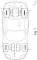
- number 1 indicates, as a whole, an electric drive car provided with four drive wheels 2 (two front drive wheels 2 and two rear drive wheels 2).
- the car 1 comprises an electric powertrain system 3, which is arranged in a front position (namely, is connected to the two front drive wheels 2), and an electric powertrain system 3, which is arranged in a rear position (namely, is connected to the two rear drive wheels 2), is completely identical to the electric powertrain system 3 arranged in a front position from a structural point of view and is completely independent of and separate from the electric powertrain system 3 arranged in a front position from a mechanical point of view.
- the road vehicle 1 comprises one single electric powertrain system 3 (arranged in a front position or arranged in a rear position) and, hence, only has two drive wheels 2.
- Each electric powertrain system 3 comprises a pair of reversible electric machines 4 (i.e. which can work both as eclectic motor, absorbing electrical energy and generating a mechanical torque, and as electric generator, absorbing mechanical energy and generating electrical energy) provided with respective shafts and a pair of drivetrains 5, which connect the electric machines 4 (namely, the shafts of the electric machines 4) to the corresponding drive wheels 2 without the interposition of a clutch.
- a pair of reversible electric machines 4 i.e. which can work both as eclectic motor, absorbing electrical energy and generating a mechanical torque, and as electric generator, absorbing mechanical energy and generating electrical energy
- the electric powertrain systems 3 are controlled by an electronic control unit 6 in a coordinated manner.
- number 7 indicates a frame of the car 1 comprising a central body 8, where the passenger compartment of the car 1 is defined.
- a central body 8 To the central body 2 there are connected (for example, bolted), at the front, a front body 9, which supports the front wheels 2 and the front electric powertrain system 3, and, at the back, a rear body 10, which supports the rear wheels 2 and the rear electric powertrain system 3.
- a rear subframe 11 is provided, which is fixed to the frame 7 (in particular, to the rear body 10 of the frame 7) in four fixing points 12 through the interposition of elastic isolating elements 13.
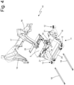
- the rear subframe 11 directly supports the rear electric powertrain system 3, which is housed inside the rear subframe 11; two axle shafts 14 (which are better shown in figure 7 ) originate from the drivetrain 5 of the powertrain system 3 and project crosswise from the rear subframe 11 in order to transmit the motion to the rear drive wheels 2.
- the rear subframe 11 offers a coupling for the two rear suspensions 15 (one of them being shown in figure 7 ); namely, the two rear suspensions 15 are connected to the sole rear subframe 11 (hence, do not have any direct connection to the rear body 10 of the frame 7).
- the four fixing points (12) are substantially arranged at the same vertical height; i.e. all four fixing points 12 have the same vertical height and, therefore, are coplanar, thus defining a horizontal plane.
- the rear body 10 of the frame 7 comprises, among other things, two "C"-shaped elements 16, each having its two ends in the area of two fixing points 12.
- the rear body 10 of the frame 7 comprises a rear cross member 17, which is arranged crosswise and connects two rear ends of the two "C"-shaped elements 16 to one another.
- the rear body 10 of the frame 7 also comprises a front cross member, which is arranged crosswise and connects two front ends of the two "C"-shaped elements 16 to one another (in the embodiment shown in the accompanying figures there is no front cross member).
- the rear body 10 of the frame 7 comprises two stiffening beams 18, each arranged longitudinally and screwed to the rear body 10 of the frame 7 in the area of the ends of a corresponding "C"-shaped element 16.
- the rear subframe 11 can be coupled to and uncoupled from the rear body 10 of the frame 7 only in the absence of the two stiffening beams 18; as a consequence, the two stiffening beams 18 need to removable and, therefore, are screwed (and not welded or glued) to the rest of the rear body 10 of the frame 7 (namely, to the two "C"-shaped elements 16) .
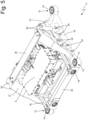
- FIG 5 artificially shows the rear subframe 11 together with the two stiffening beams 18 in the absence of the rest of the rear body 10 of the frame 7 for the sole purpose of better showing the positioning of the two stiffening beams 18 relative to the rear subframe 11; in practice, the two stiffening beams 18 can be present only in combination with the rest of the rear body 10 of the frame 7 and are screwed to the rest of the rear body 10 of the frame 7.
- each stiffening beam 18 is screwed, at the back, to the rear cross member 17; in particular, each stiffening beam 18 is screwed, at the back, to a lower face of the rear cross member 17.
- each stiffening beam 18 is screwed, at the front, to a side face of a front end of a corresponding "C"-shaped element 16.
- the rear subframe 11 comprises a base with the shape of a quadrilateral, which is obtained by joining four bars 19 and 20 and at whose vertexes there are the four fixing points 12; in particular, the rear subframe 11 comprises two longitudinal bars 19 and two transverse bars 20, which are joined to one another in order to form a quadrilateral.
- the rear subframe 11 comprises, on each side, a "C"-shaped support body 21, which has two legs originating from the quadrilateral-shaped base (in particular, from a longitudinal bar 19 of the quadrilateral-shaped base), builds - together with the base - a triangular shape holding, on the inside, a corresponding axle shaft 14 and, at its top, has a coupling 22 for a camber control bar 23 to control the camber of a corresponding rear suspension 15 (shown in figure 7 ).
- Each longitudinal bar 19 of the quadrilateral-shaped base of the rear subframe 11 laterally has couplings 24 for a corresponding rear suspension 15 (shown in figure 7 ); namely, each rear suspension 15 is laterally hinged to the quadrilateral-shaped base of the rear subframe 11.
- the rear subframe 11 comprises an upper cross member 25, which is arranged crosswise, connects the two support bodies 21 to one another and is screwed to the support bodies 21; indeed, the upper cross member 25 must be removed in order to allow the powertrain system 3 to be fitted into or removed from the rear subframe 11.
- the upper cross member 25 has to be removable and, hence, not screwed (and not welded or glued) to the rest of the rear subframe 11 (namely, to the two support bodies 21).
- the rear powertrain system 3 comprises two electric machines 4 beside one another (each of them causing the rotation of a corresponding axle shaft 14), which are both housed side by side in the rear subframe 11 (together with the two respective drivetrains 5).
- the rear powertrain system 3 comprises one single electric machine 4 (which causes the rotation of both axle shafts 14 by means of a differential), which is housed in the rear subframe 11 (together with the respective drivetrain 5).
- the rear powertrain system 3 comprises an internal combustion engine and a mechanical gearbox (which causes the rotation of both axle shafts 14 by means of a differential), which is housed in the rear subframe 11.
- the rear subframe 11 can be coupled to and uncoupled from the rear body 10 of the frame 7 only in the absence of the two stiffening beams 18; as a consequence, during the assembly of the car 1, the rear subframe 11 needs to be preliminarily fixed to the rear body 10 of the frame 7 in the area of the four fixing points 12 in the absence of the stiffening beams 18 and, then, the two stiffening beams 18 can be screwed to the rear body 10 of the frame 7, only after having fixed the rear subframe 11 to the rear body 10 of the frame 7. Similarly, in case the car 1 needs to be disassembled, the two stiffening beams 18 have to be preliminarily removed from the rear body 10 of the frame 7 before extracting the rear subframe 11 from the rear body 10 of the frame 7.
- the car 1 described above has numerous advantages.
- the car 1 described above offers top comfort thanks to the use of the rear subframe 11 connected to the rear body 10 of the frame 7 through the interposition of the elastic isolating elements 13.
- the car 1 described above also has high dynamic performances thanks to the fact that the fixing points 12 to fix the rear subframe 11 to the rear body 10 of the frame 7 are very close to the ground (namely, to the lower plane of the car 1) and that the camber control points (namely, the couplings 22 of the camber control bars 23) are distant from the ground (namely, from the lower plane of the car 1).
- the car 1 described above has a great structural efficiency (measured, for example, as specific torsional stiffness, i.e. per mass unit) thanks to the presence of the stiffening beams 18, which are removable and ensure a high torsional stiffness even in the presence of the "C"-shaped elements 16, which are a significant part of the rear body 10 of the frame 7.
- the two stiffening beams 18 "close” the shape of the "C"-shaped elements 16 (which, in the absence of the two stiffening beams 18, would have an open and, hence, definitely less stiff shape), thus significantly increasing torsional stiffness.
Landscapes
- Engineering & Computer Science (AREA)
- Mechanical Engineering (AREA)
- Chemical & Material Sciences (AREA)
- Combustion & Propulsion (AREA)
- Transportation (AREA)
- Body Structure For Vehicles (AREA)
- Arrangement Or Mounting Of Propulsion Units For Vehicles (AREA)
Applications Claiming Priority (1)
| Application Number | Priority Date | Filing Date | Title |
|---|---|---|---|
| IT202000019198 | 2020-08-04 |
Publications (2)
| Publication Number | Publication Date |
|---|---|
| EP3950468A1 true EP3950468A1 (de) | 2022-02-09 |
| EP3950468B1 EP3950468B1 (de) | 2023-07-26 |
Family
ID=72885991
Family Applications (1)
| Application Number | Title | Priority Date | Filing Date |
|---|---|---|---|
| EP21189315.1A Active EP3950468B1 (de) | 2020-08-04 | 2021-08-03 | Auto mit hinterem unterrahmen |
Country Status (2)
| Country | Link |
|---|---|
| US (1) | US11766931B2 (de) |
| EP (1) | EP3950468B1 (de) |
Families Citing this family (3)
| Publication number | Priority date | Publication date | Assignee | Title |
|---|---|---|---|---|
| US11766931B2 (en) * | 2020-08-04 | 2023-09-26 | Ferrari S.P.A. | Car provided with a rear subframe |
| US12084111B2 (en) * | 2022-09-12 | 2024-09-10 | Ferrari S.P.A. | Motor vehicle provided with a reinforcing structure |
| US20250304185A1 (en) * | 2024-03-27 | 2025-10-02 | Via Fortuna, Llc | Modular motor vehicle assembly platform |
Citations (3)
| Publication number | Priority date | Publication date | Assignee | Title |
|---|---|---|---|---|
| JP2009274618A (ja) | 2008-05-15 | 2009-11-26 | Honda Motor Co Ltd | 車両用パワーユニット |
| WO2013059679A1 (en) * | 2011-10-21 | 2013-04-25 | Fisker Automotive, Inc. | Rear-wheel drive, plug-in hybrid electric vehicle modular subframe assembly and method |
| US20200062060A1 (en) * | 2016-12-06 | 2020-02-27 | Renault S.A.S. | Linking device between an aluminium side rail of a vehicle and a control arm |
Family Cites Families (13)
| Publication number | Priority date | Publication date | Assignee | Title |
|---|---|---|---|---|
| US4429900A (en) * | 1980-11-06 | 1984-02-07 | Feher Joseph S | Automotive suspension system for maintaining the rear wheels substantially parallel to one another throughout use |
| CN106163848A (zh) * | 2014-01-21 | 2016-11-23 | 互动的全电动汽车有限责任公司 | 电力推动车辆 |
| US9701250B1 (en) * | 2016-06-09 | 2017-07-11 | Dura Operating, Llc | Motor vehicle hybrid shelf assembly |
| US11279217B2 (en) * | 2016-08-10 | 2022-03-22 | Faraday&Future Inc. | Subframe and suspension assembly |
| DE102016215623A1 (de) * | 2016-08-19 | 2018-02-22 | Volkswagen Aktiengesellschaft | Verfahren zur Herstellung einer Lenker-Lagerungsordnung eines Kraftfahrzeugs sowie Lagerungsanordnung |
| JP6845539B2 (ja) * | 2017-03-27 | 2021-03-17 | マツダ株式会社 | 自動車の後部サスペンション構造 |
| EP3539812B1 (de) * | 2018-03-13 | 2020-12-09 | FCA Italy S.p.A. | Aufhängungs- und antriebsstrangeinheit für ein elektrofahrzeug, mit bremsscheiben an einer entfernten position in bezug auf die räder |
| EP3539810A1 (de) * | 2018-03-13 | 2019-09-18 | FCA Italy S.p.A. | Elektrofahrzeug mit modularem aufbau |
| US11772487B2 (en) * | 2018-10-04 | 2023-10-03 | Ronald A. Holland | Vehicle rear drive axle |
| GB2578660B (en) * | 2019-05-13 | 2021-01-13 | Rbw Sports & Classics Ltd | Electric car sub-frame |
| CN110171472B (zh) * | 2019-07-11 | 2023-07-07 | 吉林大学 | 一种双模式后轮主动转向装置 |
| US10953715B1 (en) * | 2019-09-19 | 2021-03-23 | Bad Boy Mowers, Llc | Riding mower trailing arm suspension system |
| US11766931B2 (en) * | 2020-08-04 | 2023-09-26 | Ferrari S.P.A. | Car provided with a rear subframe |
-
2021
- 2021-08-02 US US17/391,238 patent/US11766931B2/en active Active
- 2021-08-03 EP EP21189315.1A patent/EP3950468B1/de active Active
Patent Citations (3)
| Publication number | Priority date | Publication date | Assignee | Title |
|---|---|---|---|---|
| JP2009274618A (ja) | 2008-05-15 | 2009-11-26 | Honda Motor Co Ltd | 車両用パワーユニット |
| WO2013059679A1 (en) * | 2011-10-21 | 2013-04-25 | Fisker Automotive, Inc. | Rear-wheel drive, plug-in hybrid electric vehicle modular subframe assembly and method |
| US20200062060A1 (en) * | 2016-12-06 | 2020-02-27 | Renault S.A.S. | Linking device between an aluminium side rail of a vehicle and a control arm |
Also Published As
| Publication number | Publication date |
|---|---|
| EP3950468B1 (de) | 2023-07-26 |
| US20220041055A1 (en) | 2022-02-10 |
| US11766931B2 (en) | 2023-09-26 |
Similar Documents
| Publication | Publication Date | Title |
|---|---|---|
| EP3950468B1 (de) | Auto mit hinterem unterrahmen | |
| US9045163B2 (en) | Universal chassis apparatus for automotive vehicle | |
| CN103958326B (zh) | 轿车和轿车模块 | |
| KR101184285B1 (ko) | 차량의 엔진마운팅 구조 | |
| US9221496B2 (en) | Suspension module having a skidplate | |
| US20200122566A1 (en) | Electric machine integrated axle assemblies for electrified vehicles | |
| US8496268B2 (en) | Universal chassis | |
| US9045170B2 (en) | Rear-wheel drive, plug-in hybrid electric vehicle modular subframe assembly and method | |
| US3913696A (en) | Chassis construction for a motor vehicle | |
| US8584789B2 (en) | Assembly for hanging a vibration-generating member attached inside an axle of an automobile running gear | |
| US20130221706A1 (en) | Suspension Module for a Vehicle and a Method of Manufacture | |
| US12030374B2 (en) | Bearing arrangement of a component on an axle carrier for a motor vehicle, and motor vehicle, in particular passenger car | |
| US11713080B2 (en) | Double subframes with isolation couplings | |
| KR102089486B1 (ko) | 전기차용 샤시플랫폼 모듈 | |
| US9333845B2 (en) | Vehicle mounted fuel cell assembly | |
| WO2019151131A1 (ja) | インホイールモータ駆動装置用サスペンション構造 | |
| US11642953B2 (en) | Mounting arrangement for a powertrain of a four-wheeled vehicle | |
| US4249627A (en) | Chassis and suspension arrangement for motor vehicles | |
| CN112124059B (zh) | 电动车辆 | |
| CN115649282B (zh) | 前端行驶模块及车辆 | |
| CN217969226U (zh) | 一种电机悬置系统与具有其的车辆 | |
| CN105966239B (zh) | 用于安装到车辆的后部驱动模块组件和系统 | |
| KR20130016509A (ko) | 프런트 서브프레임 구조 | |
| JPH02208172A (ja) | 車両のサブフレーム構造 | |
| RU2216456C2 (ru) | Устройство для крепления раздаточной коробки |
Legal Events
| Date | Code | Title | Description |
|---|---|---|---|
| PUAI | Public reference made under article 153(3) epc to a published international application that has entered the european phase |
Free format text: ORIGINAL CODE: 0009012 |
|
| STAA | Information on the status of an ep patent application or granted ep patent |
Free format text: STATUS: THE APPLICATION HAS BEEN PUBLISHED |
|
| AK | Designated contracting states |
Kind code of ref document: A1 Designated state(s): AL AT BE BG CH CY CZ DE DK EE ES FI FR GB GR HR HU IE IS IT LI LT LU LV MC MK MT NL NO PL PT RO RS SE SI SK SM TR |
|
| STAA | Information on the status of an ep patent application or granted ep patent |
Free format text: STATUS: REQUEST FOR EXAMINATION WAS MADE |
|
| 17P | Request for examination filed |
Effective date: 20220803 |
|
| GRAP | Despatch of communication of intention to grant a patent |
Free format text: ORIGINAL CODE: EPIDOSNIGR1 |
|
| STAA | Information on the status of an ep patent application or granted ep patent |
Free format text: STATUS: GRANT OF PATENT IS INTENDED |
|
| INTG | Intention to grant announced |
Effective date: 20230215 |
|
| GRAS | Grant fee paid |
Free format text: ORIGINAL CODE: EPIDOSNIGR3 |
|
| GRAA | (expected) grant |
Free format text: ORIGINAL CODE: 0009210 |
|
| STAA | Information on the status of an ep patent application or granted ep patent |
Free format text: STATUS: THE PATENT HAS BEEN GRANTED |
|
| P01 | Opt-out of the competence of the unified patent court (upc) registered |
Effective date: 20230525 |
|
| AK | Designated contracting states |
Kind code of ref document: B1 Designated state(s): AL AT BE BG CH CY CZ DE DK EE ES FI FR GB GR HR HU IE IS IT LI LT LU LV MC MK MT NL NO PL PT RO RS SE SI SK SM TR |
|
| REG | Reference to a national code |
Ref country code: CH Ref legal event code: EP |
|
| REG | Reference to a national code |
Ref country code: DE Ref legal event code: R096 Ref document number: 602021003756 Country of ref document: DE |
|
| REG | Reference to a national code |
Ref country code: IE Ref legal event code: FG4D |
|
| REG | Reference to a national code |
Ref country code: LT Ref legal event code: MG9D |
|
| REG | Reference to a national code |
Ref country code: NL Ref legal event code: MP Effective date: 20230726 |
|
| REG | Reference to a national code |
Ref country code: AT Ref legal event code: MK05 Ref document number: 1591654 Country of ref document: AT Kind code of ref document: T Effective date: 20230726 |
|
| PG25 | Lapsed in a contracting state [announced via postgrant information from national office to epo] |
Ref country code: NL Free format text: LAPSE BECAUSE OF FAILURE TO SUBMIT A TRANSLATION OF THE DESCRIPTION OR TO PAY THE FEE WITHIN THE PRESCRIBED TIME-LIMIT Effective date: 20230726 |
|
| PG25 | Lapsed in a contracting state [announced via postgrant information from national office to epo] |
Ref country code: GR Free format text: LAPSE BECAUSE OF FAILURE TO SUBMIT A TRANSLATION OF THE DESCRIPTION OR TO PAY THE FEE WITHIN THE PRESCRIBED TIME-LIMIT Effective date: 20231027 |
|
| PG25 | Lapsed in a contracting state [announced via postgrant information from national office to epo] |
Ref country code: IS Free format text: LAPSE BECAUSE OF FAILURE TO SUBMIT A TRANSLATION OF THE DESCRIPTION OR TO PAY THE FEE WITHIN THE PRESCRIBED TIME-LIMIT Effective date: 20231126 |
|
| PG25 | Lapsed in a contracting state [announced via postgrant information from national office to epo] |
Ref country code: SE Free format text: LAPSE BECAUSE OF FAILURE TO SUBMIT A TRANSLATION OF THE DESCRIPTION OR TO PAY THE FEE WITHIN THE PRESCRIBED TIME-LIMIT Effective date: 20230726 Ref country code: RS Free format text: LAPSE BECAUSE OF FAILURE TO SUBMIT A TRANSLATION OF THE DESCRIPTION OR TO PAY THE FEE WITHIN THE PRESCRIBED TIME-LIMIT Effective date: 20230726 Ref country code: PT Free format text: LAPSE BECAUSE OF FAILURE TO SUBMIT A TRANSLATION OF THE DESCRIPTION OR TO PAY THE FEE WITHIN THE PRESCRIBED TIME-LIMIT Effective date: 20231127 Ref country code: NO Free format text: LAPSE BECAUSE OF FAILURE TO SUBMIT A TRANSLATION OF THE DESCRIPTION OR TO PAY THE FEE WITHIN THE PRESCRIBED TIME-LIMIT Effective date: 20231026 Ref country code: LV Free format text: LAPSE BECAUSE OF FAILURE TO SUBMIT A TRANSLATION OF THE DESCRIPTION OR TO PAY THE FEE WITHIN THE PRESCRIBED TIME-LIMIT Effective date: 20230726 Ref country code: LT Free format text: LAPSE BECAUSE OF FAILURE TO SUBMIT A TRANSLATION OF THE DESCRIPTION OR TO PAY THE FEE WITHIN THE PRESCRIBED TIME-LIMIT Effective date: 20230726 Ref country code: IS Free format text: LAPSE BECAUSE OF FAILURE TO SUBMIT A TRANSLATION OF THE DESCRIPTION OR TO PAY THE FEE WITHIN THE PRESCRIBED TIME-LIMIT Effective date: 20231126 Ref country code: HR Free format text: LAPSE BECAUSE OF FAILURE TO SUBMIT A TRANSLATION OF THE DESCRIPTION OR TO PAY THE FEE WITHIN THE PRESCRIBED TIME-LIMIT Effective date: 20230726 Ref country code: GR Free format text: LAPSE BECAUSE OF FAILURE TO SUBMIT A TRANSLATION OF THE DESCRIPTION OR TO PAY THE FEE WITHIN THE PRESCRIBED TIME-LIMIT Effective date: 20231027 Ref country code: FI Free format text: LAPSE BECAUSE OF FAILURE TO SUBMIT A TRANSLATION OF THE DESCRIPTION OR TO PAY THE FEE WITHIN THE PRESCRIBED TIME-LIMIT Effective date: 20230726 Ref country code: AT Free format text: LAPSE BECAUSE OF FAILURE TO SUBMIT A TRANSLATION OF THE DESCRIPTION OR TO PAY THE FEE WITHIN THE PRESCRIBED TIME-LIMIT Effective date: 20230726 |
|
| PG25 | Lapsed in a contracting state [announced via postgrant information from national office to epo] |
Ref country code: PL Free format text: LAPSE BECAUSE OF FAILURE TO SUBMIT A TRANSLATION OF THE DESCRIPTION OR TO PAY THE FEE WITHIN THE PRESCRIBED TIME-LIMIT Effective date: 20230726 |
|
| PG25 | Lapsed in a contracting state [announced via postgrant information from national office to epo] |
Ref country code: LU Free format text: LAPSE BECAUSE OF NON-PAYMENT OF DUE FEES Effective date: 20230803 |
|
| PG25 | Lapsed in a contracting state [announced via postgrant information from national office to epo] |
Ref country code: ES Free format text: LAPSE BECAUSE OF FAILURE TO SUBMIT A TRANSLATION OF THE DESCRIPTION OR TO PAY THE FEE WITHIN THE PRESCRIBED TIME-LIMIT Effective date: 20230726 |
|
| REG | Reference to a national code |
Ref country code: DE Ref legal event code: R097 Ref document number: 602021003756 Country of ref document: DE |
|
| PG25 | Lapsed in a contracting state [announced via postgrant information from national office to epo] |
Ref country code: SM Free format text: LAPSE BECAUSE OF FAILURE TO SUBMIT A TRANSLATION OF THE DESCRIPTION OR TO PAY THE FEE WITHIN THE PRESCRIBED TIME-LIMIT Effective date: 20230726 Ref country code: RO Free format text: LAPSE BECAUSE OF FAILURE TO SUBMIT A TRANSLATION OF THE DESCRIPTION OR TO PAY THE FEE WITHIN THE PRESCRIBED TIME-LIMIT Effective date: 20230726 Ref country code: LU Free format text: LAPSE BECAUSE OF NON-PAYMENT OF DUE FEES Effective date: 20230803 Ref country code: ES Free format text: LAPSE BECAUSE OF FAILURE TO SUBMIT A TRANSLATION OF THE DESCRIPTION OR TO PAY THE FEE WITHIN THE PRESCRIBED TIME-LIMIT Effective date: 20230726 Ref country code: EE Free format text: LAPSE BECAUSE OF FAILURE TO SUBMIT A TRANSLATION OF THE DESCRIPTION OR TO PAY THE FEE WITHIN THE PRESCRIBED TIME-LIMIT Effective date: 20230726 Ref country code: DK Free format text: LAPSE BECAUSE OF FAILURE TO SUBMIT A TRANSLATION OF THE DESCRIPTION OR TO PAY THE FEE WITHIN THE PRESCRIBED TIME-LIMIT Effective date: 20230726 Ref country code: CZ Free format text: LAPSE BECAUSE OF FAILURE TO SUBMIT A TRANSLATION OF THE DESCRIPTION OR TO PAY THE FEE WITHIN THE PRESCRIBED TIME-LIMIT Effective date: 20230726 Ref country code: SK Free format text: LAPSE BECAUSE OF FAILURE TO SUBMIT A TRANSLATION OF THE DESCRIPTION OR TO PAY THE FEE WITHIN THE PRESCRIBED TIME-LIMIT Effective date: 20230726 Ref country code: MC Free format text: LAPSE BECAUSE OF FAILURE TO SUBMIT A TRANSLATION OF THE DESCRIPTION OR TO PAY THE FEE WITHIN THE PRESCRIBED TIME-LIMIT Effective date: 20230726 |
|
| REG | Reference to a national code |
Ref country code: BE Ref legal event code: MM Effective date: 20230831 |
|
| REG | Reference to a national code |
Ref country code: IE Ref legal event code: MM4A |
|
| PLBE | No opposition filed within time limit |
Free format text: ORIGINAL CODE: 0009261 |
|
| STAA | Information on the status of an ep patent application or granted ep patent |
Free format text: STATUS: NO OPPOSITION FILED WITHIN TIME LIMIT |
|
| 26N | No opposition filed |
Effective date: 20240429 |
|
| PG25 | Lapsed in a contracting state [announced via postgrant information from national office to epo] |
Ref country code: IE Free format text: LAPSE BECAUSE OF NON-PAYMENT OF DUE FEES Effective date: 20230803 |
|
| PG25 | Lapsed in a contracting state [announced via postgrant information from national office to epo] |
Ref country code: IE Free format text: LAPSE BECAUSE OF NON-PAYMENT OF DUE FEES Effective date: 20230803 Ref country code: SI Free format text: LAPSE BECAUSE OF FAILURE TO SUBMIT A TRANSLATION OF THE DESCRIPTION OR TO PAY THE FEE WITHIN THE PRESCRIBED TIME-LIMIT Effective date: 20230726 |
|
| PG25 | Lapsed in a contracting state [announced via postgrant information from national office to epo] |
Ref country code: BE Free format text: LAPSE BECAUSE OF NON-PAYMENT OF DUE FEES Effective date: 20230831 |
|
| PG25 | Lapsed in a contracting state [announced via postgrant information from national office to epo] |
Ref country code: BG Free format text: LAPSE BECAUSE OF FAILURE TO SUBMIT A TRANSLATION OF THE DESCRIPTION OR TO PAY THE FEE WITHIN THE PRESCRIBED TIME-LIMIT Effective date: 20230726 |
|
| PG25 | Lapsed in a contracting state [announced via postgrant information from national office to epo] |
Ref country code: BG Free format text: LAPSE BECAUSE OF FAILURE TO SUBMIT A TRANSLATION OF THE DESCRIPTION OR TO PAY THE FEE WITHIN THE PRESCRIBED TIME-LIMIT Effective date: 20230726 |
|
| REG | Reference to a national code |
Ref country code: CH Ref legal event code: PL |
|
| PG25 | Lapsed in a contracting state [announced via postgrant information from national office to epo] |
Ref country code: CH Free format text: LAPSE BECAUSE OF NON-PAYMENT OF DUE FEES Effective date: 20240831 |
|
| PG25 | Lapsed in a contracting state [announced via postgrant information from national office to epo] |
Ref country code: CY Free format text: LAPSE BECAUSE OF FAILURE TO SUBMIT A TRANSLATION OF THE DESCRIPTION OR TO PAY THE FEE WITHIN THE PRESCRIBED TIME-LIMIT; INVALID AB INITIO Effective date: 20210803 |
|
| PG25 | Lapsed in a contracting state [announced via postgrant information from national office to epo] |
Ref country code: HU Free format text: LAPSE BECAUSE OF FAILURE TO SUBMIT A TRANSLATION OF THE DESCRIPTION OR TO PAY THE FEE WITHIN THE PRESCRIBED TIME-LIMIT; INVALID AB INITIO Effective date: 20210803 |
|
| PGFP | Annual fee paid to national office [announced via postgrant information from national office to epo] |
Ref country code: DE Payment date: 20250827 Year of fee payment: 5 |
|
| PGFP | Annual fee paid to national office [announced via postgrant information from national office to epo] |
Ref country code: IT Payment date: 20250714 Year of fee payment: 5 |
|
| PGFP | Annual fee paid to national office [announced via postgrant information from national office to epo] |
Ref country code: GB Payment date: 20250826 Year of fee payment: 5 |
|
| PGFP | Annual fee paid to national office [announced via postgrant information from national office to epo] |
Ref country code: FR Payment date: 20250825 Year of fee payment: 5 |
|
| PG25 | Lapsed in a contracting state [announced via postgrant information from national office to epo] |
Ref country code: TR Free format text: LAPSE BECAUSE OF FAILURE TO SUBMIT A TRANSLATION OF THE DESCRIPTION OR TO PAY THE FEE WITHIN THE PRESCRIBED TIME-LIMIT Effective date: 20230726 |