EP3950501A1 - Antriebsvorrichtung eines passagiers - Google Patents
Antriebsvorrichtung eines passagiers Download PDFInfo
- Publication number
- EP3950501A1 EP3950501A1 EP21198135.2A EP21198135A EP3950501A1 EP 3950501 A1 EP3950501 A1 EP 3950501A1 EP 21198135 A EP21198135 A EP 21198135A EP 3950501 A1 EP3950501 A1 EP 3950501A1
- Authority
- EP
- European Patent Office
- Prior art keywords
- thrusters
- passenger
- thrust
- platform
- propulsion device
- Prior art date
- Legal status (The legal status is an assumption and is not a legal conclusion. Google has not performed a legal analysis and makes no representation as to the accuracy of the status listed.)
- Granted
Links
Images



Classifications
-
- B—PERFORMING OPERATIONS; TRANSPORTING
- B64—AIRCRAFT; AVIATION; COSMONAUTICS
- B64C—AEROPLANES; HELICOPTERS
- B64C39/00—Aircraft not otherwise provided for
- B64C39/02—Aircraft not otherwise provided for characterised by special use
- B64C39/026—Aircraft not otherwise provided for characterised by special use for use as personal propulsion unit
-
- B—PERFORMING OPERATIONS; TRANSPORTING
- B63—SHIPS OR OTHER WATERBORNE VESSELS; RELATED EQUIPMENT
- B63B—SHIPS OR OTHER WATERBORNE VESSELS; EQUIPMENT FOR SHIPPING
- B63B34/00—Vessels specially adapted for water sports or leisure; Body-supporting devices specially adapted for water sports or leisure
- B63B34/10—Power-driven personal watercraft, e.g. water scooters; Accessories therefor
- B63B34/15—Power-driven personal watercraft, e.g. water scooters; Accessories therefor for hydroflight sports
-
- B—PERFORMING OPERATIONS; TRANSPORTING
- B63—SHIPS OR OTHER WATERBORNE VESSELS; RELATED EQUIPMENT
- B63H—MARINE PROPULSION OR STEERING
- B63H11/00—Marine propulsion by water jets
- B63H11/02—Marine propulsion by water jets the propulsive medium being ambient water
- B63H11/04—Marine propulsion by water jets the propulsive medium being ambient water by means of pumps
-
- B—PERFORMING OPERATIONS; TRANSPORTING
- B64—AIRCRAFT; AVIATION; COSMONAUTICS
- B64C—AEROPLANES; HELICOPTERS
- B64C15/00—Attitude, flight direction, or altitude control by jet reaction
- B64C15/02—Attitude, flight direction, or altitude control by jet reaction the jets being propulsion jets
- B64C15/12—Attitude, flight direction, or altitude control by jet reaction the jets being propulsion jets the power plant being tiltable
-
- B—PERFORMING OPERATIONS; TRANSPORTING
- B64—AIRCRAFT; AVIATION; COSMONAUTICS
- B64C—AEROPLANES; HELICOPTERS
- B64C29/00—Aircraft capable of landing or taking-off vertically, e.g. vertical take-off and landing [VTOL] aircraft
- B64C29/0008—Aircraft capable of landing or taking-off vertically, e.g. vertical take-off and landing [VTOL] aircraft having its flight directional axis horizontal when grounded
- B64C29/0041—Aircraft capable of landing or taking-off vertically, e.g. vertical take-off and landing [VTOL] aircraft having its flight directional axis horizontal when grounded the lift during taking-off being created by jet motors
- B64C29/0075—Aircraft capable of landing or taking-off vertically, e.g. vertical take-off and landing [VTOL] aircraft having its flight directional axis horizontal when grounded the lift during taking-off being created by jet motors the motors being tiltable relative to the fuselage
-
- B—PERFORMING OPERATIONS; TRANSPORTING
- B64—AIRCRAFT; AVIATION; COSMONAUTICS
- B64D—EQUIPMENT FOR FITTING IN OR TO AIRCRAFT; FLIGHT SUITS; PARACHUTES; ARRANGEMENT OR MOUNTING OF POWER PLANTS OR PROPULSION TRANSMISSIONS IN AIRCRAFT
- B64D27/00—Arrangement or mounting of power plants in aircraft; Aircraft characterised by the type or position of power plants
- B64D27/02—Aircraft characterised by the type or position of power plants
- B64D27/24—Aircraft characterised by the type or position of power plants using steam or spring force
-
- B—PERFORMING OPERATIONS; TRANSPORTING
- B64—AIRCRAFT; AVIATION; COSMONAUTICS
- B64D—EQUIPMENT FOR FITTING IN OR TO AIRCRAFT; FLIGHT SUITS; PARACHUTES; ARRANGEMENT OR MOUNTING OF POWER PLANTS OR PROPULSION TRANSMISSIONS IN AIRCRAFT
- B64D37/00—Arrangements in connection with fuel supply for power plant
- B64D37/02—Tanks
- B64D37/06—Constructional adaptations thereof
-
- B—PERFORMING OPERATIONS; TRANSPORTING
- B63—SHIPS OR OTHER WATERBORNE VESSELS; RELATED EQUIPMENT
- B63H—MARINE PROPULSION OR STEERING
- B63H11/00—Marine propulsion by water jets
- B63H2011/006—Marine propulsion by water jets with propulsive medium supplied from sources external to propelled vessel, e.g. water from public water supply
-
- Y—GENERAL TAGGING OF NEW TECHNOLOGICAL DEVELOPMENTS; GENERAL TAGGING OF CROSS-SECTIONAL TECHNOLOGIES SPANNING OVER SEVERAL SECTIONS OF THE IPC; TECHNICAL SUBJECTS COVERED BY FORMER USPC CROSS-REFERENCE ART COLLECTIONS [XRACs] AND DIGESTS
- Y02—TECHNOLOGIES OR APPLICATIONS FOR MITIGATION OR ADAPTATION AGAINST CLIMATE CHANGE
- Y02T—CLIMATE CHANGE MITIGATION TECHNOLOGIES RELATED TO TRANSPORTATION
- Y02T50/00—Aeronautics or air transport
-
- Y—GENERAL TAGGING OF NEW TECHNOLOGICAL DEVELOPMENTS; GENERAL TAGGING OF CROSS-SECTIONAL TECHNOLOGIES SPANNING OVER SEVERAL SECTIONS OF THE IPC; TECHNICAL SUBJECTS COVERED BY FORMER USPC CROSS-REFERENCE ART COLLECTIONS [XRACs] AND DIGESTS
- Y02—TECHNOLOGIES OR APPLICATIONS FOR MITIGATION OR ADAPTATION AGAINST CLIMATE CHANGE
- Y02T—CLIMATE CHANGE MITIGATION TECHNOLOGIES RELATED TO TRANSPORTATION
- Y02T50/00—Aeronautics or air transport
- Y02T50/30—Wing lift efficiency
-
- Y—GENERAL TAGGING OF NEW TECHNOLOGICAL DEVELOPMENTS; GENERAL TAGGING OF CROSS-SECTIONAL TECHNOLOGIES SPANNING OVER SEVERAL SECTIONS OF THE IPC; TECHNICAL SUBJECTS COVERED BY FORMER USPC CROSS-REFERENCE ART COLLECTIONS [XRACs] AND DIGESTS
- Y02—TECHNOLOGIES OR APPLICATIONS FOR MITIGATION OR ADAPTATION AGAINST CLIMATE CHANGE
- Y02T—CLIMATE CHANGE MITIGATION TECHNOLOGIES RELATED TO TRANSPORTATION
- Y02T50/00—Aeronautics or air transport
- Y02T50/60—Efficient propulsion technologies, e.g. for aircraft
Definitions
- This station is capable of supplying the nozzles sufficiently to cause the passenger to take off, transformed in a way into a human rocket.
- the low autonomy and the dangerousness of such devices have kept them in relative confidentiality.
- the platform 11 may have means for holding a passenger on the upper face of said platform 11.
- said means for holding may consist - as indicated in the figure 1 - in a pair of slippers, foot straps, also known under the Anglo-Saxon name “Foot Straps", or binding boots 16 of a type similar to what can be found, for example, in the practice of wakeboarding.
- the latter may comprise a second thrust sub-group cooperating with the platform, the support means of the thrust group being arranged to support said second thrust group parallel to the first sub-group of thrust, while minimizing the distance between a median plane passing through the center of gravity of the device body and the direction of ejection of the gas flow through the ejection nozzle of each propellant.
- one of said thrusters can be a turbojet engine.
- the latter may advantageously further comprise a fuel tank in fluid communication with the thrusters of the thrust unit to supply the latter with fuel, said tank cooperating with the body of the device or the passenger.
- Such a propulsion device may further comprise an attitude and/or trajectory sensor cooperating with the body of the device substantially at the position of the latter's center of gravity and with the processing means, the latter generating the power control thrusters from information delivered by the attitude and/or trajectory sensor together with an instruction produced by the man-machine interface.
- the processing means can generate power commands for said heading-correcting secondary thrusters from information delivered by the attitude and/or trajectory sensor to actuate one of said secondary thrusters and maintain the current trajectory of said body, in l absence of instructions produced by the man-machine interface.
- the processing means can generate power commands for said trim-correcting secondary thrusters from information delivered by the trim and/or trajectory sensor to actuate one of said thrusters secondary attitude correctors and maintain a substantially horizontal attitude of said body, in the absence of setpoint produced by the man-machine interface.
- the latter can advantageously comprise means for maintaining said passenger on the platform.
- the figure 2A shows a perspective view of a first preferred embodiment of a device 10 for propelling a passenger 1 according to the invention.
- a device 10 comprises a main body 10a mainly in the form of a platform 11 on which a passenger 1 can take place.
- the invention provides that several passengers can optionally take position simultaneously on said platform 11.
- the platform 11 has, as such, one or more beaches 11a arranged to accommodate the feet or shoes of passenger 1, as indicated more distinctively in particular by the 2D figure .
- the body 10a of the propulsion device 10 described in connection with the figure 2A and 2D comprises a thrust group 12 cooperating with the platform 11.
- Such means 17 may consist in particular of four feet of sufficient length so that the ejection nozzle(s) of the thrust unit 12 cannot strike the ground and also to provide some stability, when the device is on the ground or on a take-off station, not shown in figures 2A to 2C , so that the passenger can effectively take up position on the platform 11.
- Such means 17 could consist of a pair of skis or any other element capable of ensuring a certain stability depending on the nature of the ground or the support of the device.
- the bulk caused by the four propellants for example jet engines, remains entirely compatible with the desired methods of use.
- the propulsion device 10 remains perfectly maneuverable, even if one of the thrusters were to malfunction.
- the thrust group 12 can advantageously comprise two secondary thrusters 19a and 19b correcting course.
- the latter are advantageously arranged eccentrically along a transverse axis of the platform.
- the invention provides for being able to add to all or part of the thrusters of the thrust subgroup(s) 12a, 12b an orientable fluid outlet, of the steerable cone type of a fluid outlet of a jet ski for example, which would cooperate with the nozzle for ejecting the gas flow from the propellant(s) concerned, according to one or more mechanical connections respective adapted, such as for example pivot or embedding connections.
- the body 10a of a propulsion device 10 may comprise a fairing 13u, optionally in the form of one or more fairing elements integral with each other, cooperating with the platform 11 and/or the support means 14, by any reversible or irreversible embedding mechanical connection (welding, screwing, for example) or constituting with said platform 11 and/or support means 14 the same physical entity.
- the function of such a fairing 13u is to prevent any direct contact between the thrust group 12 and the passenger 1.
- the morphology (dimensions, shape) of such a fairing 13u will thus be arranged to adapt to the dimensions of the thrust group.
- said fairing 13u can advantageously comprise a grid , not shown in 2D figure , the configuration of which makes it possible to partially obscure said inlet 18 and thus limit or prevent the aspiration of foreign bodies through said air inlet 18, while preserving the fluid exchange between the outside world and the thrusters.
- the 2D figure further describes the operation of a lower fairing 13d, cooperating by means of any mechanical embedding connection, also ensuring a function of protecting the passenger or the environment close to the fluid outlets or gas ejection nozzles of the thrusters of the thrust subgroups 12a and 12b.
- the 2D figure also describes the presence of secondary thrusters 19a and 19b correcting course located laterally and not centrally, unlike thrust subgroups 12a and 12b. We will describe the contribution of such secondary thrusters in connection with the detailed presentation of an example of a thrust group illustrated by the figure 2E .
- such a thrust unit 12 comprises two thrust sub-units 12a and 12b each comprising two thrusters, referenced 12a1 and 12a2 for the first, and 12b1 and 12b2 for the second.
- the invention provides that the support means 14 can be arranged to orient the direction of ejection of the gas flow by the ejection nozzle of each propellant of each thrust subgroup 12a and 12b, so that said gas flow ejection direction describes an angle ⁇ comprised between -10° and +10° with a median axis AM10 of the platform 11 or of the body 10a.
- a thrust unit 12 supported by support means 14 of a device 10 described in connection with the figure 2E has said support means 14 comprising extensions 15a and 15b respectively comprising a pair of protuberances or spacers 15p and 15s. These are positioned along an axis normal to the longitudinal axis of each extension 15a or 15b in order to cooperate with the platform 11. The latter can thus be fixed by screwing, said protuberances being threaded in this case. Any other mode of cooperation between the support means 14 and the platform 11 could be imagined according to the invention.
- the respective heights of said protrusions 15p and 15s make it possible to adjust this configuration by regulating said height hp.
- Said fuel is then delivered by said tank through the drain mouth arranged to cooperate with a supply conduit, not shown for simplification in the figures, the ends of which are respectively connected to the tank, more precisely to the drain mouth, to collect the fuel and to a collector means, also not shown in the figures, to supply the thrusters with fuel.
- a collector means supplies each thermal thruster with fuel. It thus cooperates by fluidic connection with said propellants and the tank.
- the envelope of said tank may advantageously be flexible, such as a pocket degassed beforehand before being filled with fuel.
- a pocket degassed beforehand improves the comfort and safety of the passenger in the event of a fall in particular and prevents any risk of defusing the fuel supply to the thrusters.
- the interface 60 comprises electronic means 62 for processing the various information collected, by the trigger 61 and other buttons and/or sensors of said interface 60, to produce instructions that can be interpreted by the means for processing such instructions on board the body 10a of the propulsion device 10.
- the interface 60 and said processing means present on the body 10a of the device 10 comprise wired or advantageously wireless communication means, for example by radio.
- information related to the operation of the thrust unit can be elaborated by said processing means and returned to the passenger 1 via one or more graphic interfaces 20a and/or 20b, such as screens or indicator lights. , advantageously positioned on the platform 11 as illustrated by the 2D figure , by way of non-limiting example, near the beaches 11a.
- the body 10a of the said device 10 it may be advantageous to position the body 10a of the said device 10 so that the thrusters of the thrust sub-units 12a and 12b are oriented substantially horizontally.
- the fuel for example kerosene
- the invention provides for as such, a take-off station arranged to allow tilting of the body 10a when starting the thrust unit 12, then to position said body 10a so that a passenger 1 can easily take place on the beaches 11a.
- the invention further provides a second embodiment of a propulsion device according to the invention.
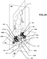
- An advantageous example is presented by the figures 3A to 3F .
- the first and previous example (described in connection with the figures 2A to 2E ) is intended more for playful applications for which the agility of the pilot and/or the passenger(s) is very often put to the test.
- the invention provides for Stahling the motorcycle as known today.
- structurally and physically distinct such a second exemplary device is similar in design to that described in connection with the figures 2A to 2E .
- a support of the front of the foot of the passenger 1 may signify a setpoint of inclination of the plate of the device 10 on the front of the latter which may thus “nose down”.
- an actuation of said footrest, by pressing the heel of said passenger 1 may signify an instruction ordering the device 10 to rear up.
- Any other set point interface could, instead of or in addition to the handlebar 11c and/or the footrest, be operated.
- the invention thus provides that electronic processing means, present on the body 10a of the device 10, can exploit information delivered by an inclinometer affixed to a garment or an accessory of the passenger 1 or integrated into said garment or accessory.
- the inclination of the bust of said passenger 1 can be translated by said electronic processing means into a setpoint for increasing the power of the thrust group 12, or even an inclination of the thrusters of such a group 12, as we will see later.
- a deceleration instruction can be generated by the electronic processing means of the device 10.
- Such a sensor cooperates by wire or by coupling, with processing means merging or complementary to those mentioned above.
- processing means consisting for example, if they are distinct, of one or more microcontrollers or electronic card(s), are advantageously arranged, that is to say programmed, to cooperate, by wire connection or by coupling, that is to say via a wireless link by means of a short-range communication protocol of the Bluetooth type or equivalent, with the processing means arranged to produce one or more power commands, ultimately transmitted to certain thrusters of the device 10, from information delivered by said attitude and/or trajectory sensor together with one of the instructions previously mentioned and produced, thanks to a distributed man-machine interface, unlike the remote control 60 previously described in connection with the figure 5 which centralizes the main setpoint devices, constituted for example by the handlebars 11c and/or the footrests 11d or any other equivalent element, when the latter comprise sensors.
- Figure 3A also allows us to define the different planes that we will alternately call “longitudinal”, “transverse” or “median”, respectively referenced PL, PT and PM in Figure 3A , in the light of which we can describe in more detail the arrangement of the body 10a of a second example of propulsion device 10.
- each thruster 12a1 to 12a6 The respective exhaust nozzles of said thrusters 12a1 to 12a6 are all parallel to each other.
- the direction of ejection of the gas flow by each ejection nozzle of each thruster 12a1 to 12a6 is substantially opposite to the direction of a longitudinal axis oriented AL1 from the chest towards the head of the passenger 1.
- the support means 14 of the thrusters 12a1 to 12a6 make it possible to tilt said thrusters by an angle ⁇ of between -45° and 45°, or at least to tilt said angle ⁇ the axis AL12 of the outputs of respective gaseous fluid ejection, in a median plane PM of the body 10a of the device 10, with respect to a nominal fluid ejection direction, described by the Figure 3E , that is to say substantially normal to a longitudinal axis AL10 of the body 10a of the device 10.
- the thrusters of the thrust unit 12 project the device 10 along a vertical trajectory.
- said thrusters create a forward movement of said device 10, when said fluid ejection directions are oriented in accordance with the figure 3F .
- the fluid ejection directions of the thrusters of the same thrust sub-group 12a can thus be oriented under the impetus of an actuator 14c, such as, by way of non-limiting example, a cylinder, whose stroke causes the joint inclination of said gaseous fluid outlets.
- an actuator 14c can advantageously be controlled via commands drawn up by the processing means mentioned previously and present on the body 10a of the device 10, from control instructions emanating from the passenger 1.
- said actuator 14c can be at rest, as indicated by Figure 3E , when the sensors 63 and/or 64 are activated by the passenger 1, thus delivering deceleration instructions.
- the height of the saddle 11a of said passenger 1 can advantageously be adjustable in height, according to the weight or the morphology of the latter, or even also according to the sensations or the behavior of the device 10 sought by said passenger 1, to provide any passenger 1 a very maneuverable propulsion device.
- the thrust unit 12 of such a device 10 can advantageously comprise secondary thrusters 19a and 19b which correct the course.
- the latter can be supported by the support means 14 and arranged eccentrically along a transverse axis of the platform 11, like the course-correcting secondary thrusters of the device 10 previously described in conjunction with the figure 2A .
- said heading-correcting secondary thrusters may consist of two pairs 19a and 19b of thrusters arranged to eject a fluid into opposite directions along axes substantially parallel to a transverse axis of the body 10a.
- these thrusters By being actuated non-simultaneously, these thrusters create sufficient torque to cause a rotation around a central axis of the body 10a.
- the thruster of the pair 19a located at the front of the body 10a whose ejection nozzle rejects a fluid towards the left of said body 10a
- the thruster of the pair 19b located at the rear of the body 10a the ejection nozzle of which rejects a fluid towards the right of said body 10a, the latter is automatically oriented to its right and vice versa.
- the invention provides for being able to add to all or part of the thrusters of the thrust subgroup(s) 12a, 12b an orientable fluid outlet, of the steerable cone type of a fluid outlet of a jet ski for example, which would cooperate with the nozzle for ejecting the gas stream of the propellant(s) concerned, according to one or more suitable respective mechanical connections, such as for example connections pivot or recessed.
- the function of said course-correcting secondary thrusters 19a and 19b can be reinforced by the presence of a centreboard or gybe, in the form for example of an optional substantially planar element, oriented along a plane parallel to a median plane of the body 10a and orientable, along a pivot-type connection with an axis parallel to a median axis of the body 10a.
- a centreboard or gybe in the form for example of an optional substantially planar element, oriented along a plane parallel to a median plane of the body 10a and orientable, along a pivot-type connection with an axis parallel to a median axis of the body 10a.
- an optional element not shown in the figures for simplification, can advantageously be controlled by an actuator with electrical controls.
- electrical controls can be developed by the means processing electronics present on the body 10a of the device 10 together with those intended for the thrusters 19a and 19b.
- Such a propulsion device 10 can also comprise secondary thrusters 19c and 19d that correct the attitude.
- the latter are presented in an advantageous but non-limiting way, in the form of electric turbines. They are respectively located at the ends of the body 10a of the device 10 and held by the support means 14. They are oriented in the same direction parallel to a median axis AM10 of the body 10a of the device 10.
- the thruster 19d located at the rear of said body 10a is actuated to correct automatically the horizontality of the plate, thus unloading the passenger 1 from any tedious compensation of said attitude.
- the attitude of said body 10a can be voluntarily modified by the passenger 1, by means of piloting instructions mentioned above taken into account by said processing means present on the body 10a of the device 10.
- the passenger 1 can thus modify as desired all directions of movement of its propulsion device with great intuitiveness, like a pilot of a terrestrial motorcycle.
- the invention provides, on an optional basis, that the automatic operation of the heading corrector secondary thrusters 19a, 19b and/or attitude correctors 19c, 19d can be deactivated, that is to say that allowing, by the sole operation of the sensors attitude and/or trajectory present on the body 10a, to maintain a heading or an attitude independently of piloting instructions emanating from the will of the passenger.
- Such projecting means may consist in particular of feet of sufficient length for the or the ejection nozzles of the thrust unit 12 cannot hit the ground and also to offer a certain stability, when the device 10 is placed on the ground or on a take-off station also not described by said figures 3A to 3F , so that the passenger 1 can effectively take a position on the platform 11.
- such projecting means could consist of a pair of skis or any other elements capable of ensuring a certain stability depending on the nature of the ground or the support of the device 10
- such projecting means may be provided retractable or retractable, for example telescopic.
- the figures do not describe the fluidic connection, comprising for example a set of hoses, manifolds and/or connections, between the said fuel tank(s) and the thrusters of the body 10a for conveying the said fuel to the said thrusters.
- the invention provides that it is possible to add to the passenger 1 an additional fuel tank which can, if necessary, also be in fluid communication with said thrusters.
- the body of such a device in particular a platform 11 and support means 14, can cooperate with, or include, a thrust group comprising one or more thrust sub-groups, in this case two thrust sub-groups 12a and 12b of eight thermal thrusters each.
- the number of sub-groups as well as the respective numbers of thrusters of said thrust sub-groups will be determined according to the configuration of the body of the propulsion device, the load that it is desired to convey and the desired performance and autonomy.
- the invention also provides for being able to add to all or part of the thrusters of the thrust subgroup(s) 12a, 12b an adjustable fluid outlet, of the adjustable cone type of a fluid outlet of a jet ski for example , which would cooperate with the gas stream ejection nozzle of the propellant(s) concerned.
- an adjustable fluid outlet of the adjustable cone type of a fluid outlet of a jet ski for example , which would cooperate with the gas stream ejection nozzle of the propellant(s) concerned.
- the figure 2F which describes two views, respectively from the front and from the side, of an example of thrust unit 12 comprising two thrust sub-units 12a and 12b.
- the figure 2F highlights the propellant 12b1 whose nominal direction AL12b of gas flow ejection is represented by a broken line.
- the effect of the TRIM consists in moving the engine away from or closer to the transom of the boat, in order to modify the angle of thrust of the motorized propeller and, consequently, the attitude of the said boat.
- Such an adaptation of the fluid outlets of the thrusters of a propulsion device according to the invention, whether it conforms to the first, second or third embodiments, that is to say such as those described by way of examples according to the figure 2A , 3A Where 4 promotes rectilinear movements, or even the speed of movement, of the propulsion device while maintaining a horizontal attitude of the body of the latter.
Landscapes
- Engineering & Computer Science (AREA)
- Aviation & Aerospace Engineering (AREA)
- Chemical & Material Sciences (AREA)
- Combustion & Propulsion (AREA)
- Mechanical Engineering (AREA)
- Ocean & Marine Engineering (AREA)
- Toys (AREA)
- Structures Of Non-Positive Displacement Pumps (AREA)
- Motorcycle And Bicycle Frame (AREA)
- Aiming, Guidance, Guns With A Light Source, Armor, Camouflage, And Targets (AREA)
- Magnetic Bearings And Hydrostatic Bearings (AREA)
- Soil Working Implements (AREA)
- Linear Motors (AREA)
- Vending Machines For Individual Products (AREA)
- Body Structure For Vehicles (AREA)
- Business, Economics & Management (AREA)
- Emergency Management (AREA)
- Ultra Sonic Daignosis Equipment (AREA)
- Escalators And Moving Walkways (AREA)
- Fittings On The Vehicle Exterior For Carrying Loads, And Devices For Holding Or Mounting Articles (AREA)
- Braking Arrangements (AREA)
Applications Claiming Priority (4)
| Application Number | Priority Date | Filing Date | Title |
|---|---|---|---|
| FR1653136A FR3049931B1 (fr) | 2016-04-08 | 2016-04-08 | Dispositif de propulsion d'un passager |
| FR1654171A FR3049932B1 (fr) | 2016-04-08 | 2016-05-10 | Dispositif de propulsion d'un passager |
| EP17719865.2A EP3439954B1 (de) | 2016-04-08 | 2017-04-06 | Vorrichtung zum antrieb eines passagiers |
| PCT/FR2017/050829 WO2017174944A1 (fr) | 2016-04-08 | 2017-04-06 | Dispositif de propulsion d'un passager |
Related Parent Applications (2)
| Application Number | Title | Priority Date | Filing Date |
|---|---|---|---|
| EP17719865.2A Division EP3439954B1 (de) | 2016-04-08 | 2017-04-06 | Vorrichtung zum antrieb eines passagiers |
| EP17719865.2A Division-Into EP3439954B1 (de) | 2016-04-08 | 2017-04-06 | Vorrichtung zum antrieb eines passagiers |
Publications (2)
| Publication Number | Publication Date |
|---|---|
| EP3950501A1 true EP3950501A1 (de) | 2022-02-09 |
| EP3950501B1 EP3950501B1 (de) | 2025-11-12 |
Family
ID=56263910
Family Applications (2)
| Application Number | Title | Priority Date | Filing Date |
|---|---|---|---|
| EP17719865.2A Active EP3439954B1 (de) | 2016-04-08 | 2017-04-06 | Vorrichtung zum antrieb eines passagiers |
| EP21198135.2A Active EP3950501B1 (de) | 2016-04-08 | 2017-04-06 | Antriebsvorrichtung eines passagiers |
Family Applications Before (1)
| Application Number | Title | Priority Date | Filing Date |
|---|---|---|---|
| EP17719865.2A Active EP3439954B1 (de) | 2016-04-08 | 2017-04-06 | Vorrichtung zum antrieb eines passagiers |
Country Status (13)
| Country | Link |
|---|---|
| US (2) | US11453479B2 (de) |
| EP (2) | EP3439954B1 (de) |
| JP (2) | JP6978795B2 (de) |
| CN (2) | CN109562832B (de) |
| AU (2) | AU2017246988B2 (de) |
| CA (2) | CA3193615C (de) |
| ES (2) | ES2939170T3 (de) |
| FR (2) | FR3049931B1 (de) |
| IL (2) | IL287054B2 (de) |
| PL (1) | PL3950501T3 (de) |
| PT (1) | PT3950501T (de) |
| SG (2) | SG10202111205XA (de) |
| WO (2) | WO2017174942A1 (de) |
Families Citing this family (15)
| Publication number | Priority date | Publication date | Assignee | Title |
|---|---|---|---|---|
| FR3049931B1 (fr) | 2016-04-08 | 2018-05-18 | Zipair | Dispositif de propulsion d'un passager |
| EP3495262B1 (de) * | 2017-12-07 | 2023-09-27 | Zipair | Antriebsvorrichtung mit einer plattform zum unterstützen eines fluggasts |
| JP6966643B2 (ja) * | 2018-06-19 | 2021-11-17 | 本田技研工業株式会社 | 飛行体及びその制御方法 |
| JP6986632B2 (ja) * | 2018-06-19 | 2021-12-22 | 本田技研工業株式会社 | 飛行体及びその制御方法 |
| WO2020245513A1 (fr) * | 2019-06-07 | 2020-12-10 | Zipair | Groupe de poussée pour dispositif de propulsion et dispositif de propulsion associe |
| CN110262366A (zh) * | 2019-07-23 | 2019-09-20 | 西安名都光电科技有限公司 | 一种水动力智能机器人及其控制方法 |
| JPWO2021070263A1 (de) * | 2019-10-08 | 2021-04-15 | ||
| FR3107697B1 (fr) * | 2020-03-02 | 2025-03-14 | Zipair | Dispositif de propulsion et procédé de pilotage de l’atterrissage d’un tel dispositif de propulsion associé |
| US11845548B2 (en) * | 2021-06-29 | 2023-12-19 | Nazareno Cruzada | Jet powered personal flying machine with customizable framework and a single control stick, attached at the front and center of the base frame |
| CN113716039A (zh) * | 2021-08-30 | 2021-11-30 | 山东元一动力科技有限公司 | 一种喷气动力飞行踏板装置 |
| FR3128200B1 (fr) | 2021-10-20 | 2024-06-21 | Zipair | Dispositif volant hybride |
| FR3128198A1 (fr) | 2021-10-20 | 2023-04-21 | Zipair | Procédé de pilotage d’un groupe de poussée pour dispositif de propulsion |
| US12024285B1 (en) | 2022-03-10 | 2024-07-02 | Skypad Tech, Inc. | Modular mobility system including thrusters movably connected to a support structure |
| US12145753B2 (en) * | 2022-08-09 | 2024-11-19 | Pete Bitar | Compact and lightweight drone delivery device called an ArcSpear electric jet drone system having an electric ducted air propulsion system and being relatively difficult to track in flight |
| US12168510B2 (en) * | 2023-02-07 | 2024-12-17 | Hunter William KOWALD | Compact personal flight vehicle |
Citations (11)
| Publication number | Priority date | Publication date | Assignee | Title |
|---|---|---|---|---|
| US3243144A (en) | 1964-07-17 | 1966-03-29 | Bell Aerospace Corp | Personel propulsion unit |
| US3277858A (en) | 1966-01-27 | 1966-10-11 | Thomas J Athey | Propulsion means for diver |
| US3381917A (en) | 1966-11-08 | 1968-05-07 | Bell Aerospace Corp | Personnel flying device |
| US4447024A (en) | 1982-02-08 | 1984-05-08 | Williams International | Airborne vehicle |
| US20070017722A1 (en) * | 2003-02-07 | 2007-01-25 | St Louis Daniel M | Levitating platform |
| US20070034738A1 (en) * | 2002-01-07 | 2007-02-15 | Sanders John K Jr | Aerodynamically stable, vtol aircraft |
| US7258301B2 (en) | 2004-03-26 | 2007-08-21 | Raymond Li | Personal propulsion device |
| US20080014811A1 (en) | 2006-07-12 | 2008-01-17 | Eugene Zeyger | Personal flying water jet apparatus |
| US8336805B1 (en) | 2011-09-19 | 2012-12-25 | Person Water Craft Product | Device and system for propelling a passenger |
| WO2015103700A1 (en) * | 2014-01-07 | 2015-07-16 | 4525612 Canada Inc. Dba Maginaire | Personal flight vehicle |
| WO2015145101A1 (en) * | 2014-03-27 | 2015-10-01 | Malloy Aeronautics Ltd | Rotor-lift aircraft |
Family Cites Families (50)
| Publication number | Priority date | Publication date | Assignee | Title |
|---|---|---|---|---|
| US2417896A (en) * | 1943-08-10 | 1947-03-25 | Charles H Zimmerman | Helicopter flying apparatus |
| US2625229A (en) * | 1950-05-19 | 1953-01-13 | Stanley Van Voorhees | Power-driven ski |
| US2943816A (en) * | 1954-07-06 | 1960-07-05 | Hiller Aircraft Corp | Vertical take-off high-speed aircraft |
| US3034746A (en) * | 1958-03-17 | 1962-05-15 | Temple Donald E De | Helicopter and control mechanism therefor |
| US3443775A (en) * | 1965-06-23 | 1969-05-13 | Williams Res Corp | Flight belt |
| FR1532428A (fr) * | 1967-05-23 | 1968-07-12 | Sud Aviation | Aérodyne individuel à propulsion et sustentation par réaction |
| US3556438A (en) * | 1969-09-02 | 1971-01-19 | Ludwig F Meditz | Airborne vehicle |
| US3662973A (en) * | 1970-07-31 | 1972-05-16 | Nasa | Flight control system |
| US4203566A (en) * | 1978-08-21 | 1980-05-20 | United Aircraft Products, Inc. | Air inlet control for aircraft or the like |
| US5395076A (en) * | 1993-03-19 | 1995-03-07 | Martin Marietta Corporation | Spacecraft velocity change maneuvers by variable arcjets |
| US5779188A (en) * | 1993-09-21 | 1998-07-14 | Frick; Alexander | Flight device |
| IT1297109B1 (it) * | 1997-12-10 | 1999-08-03 | Franco Capanna | Aeromobile ibrido a decollo e atterraggio verticale e volo orizzontale aerodinamicamente autosostentato |
| US6179247B1 (en) * | 1999-02-09 | 2001-01-30 | Karl F. Milde, Jr. | Personal air transport |
| US20020113165A1 (en) * | 2000-12-13 | 2002-08-22 | Michael Moshier | Aircraft and control system |
| US20030062443A1 (en) | 2001-10-02 | 2003-04-03 | Joseph Wagner | VTOL personal aircraft |
| JP2003137192A (ja) * | 2001-10-31 | 2003-05-14 | Mitsubishi Heavy Ind Ltd | 垂直離着陸機 |
| US6769648B2 (en) * | 2002-04-19 | 2004-08-03 | William L. Klima | Personal aircraft device |
| HK1053231A2 (en) * | 2002-08-15 | 2003-09-26 | 刘京庭 | Superman air motor |
| JP4155081B2 (ja) * | 2003-04-02 | 2008-09-24 | トヨタ自動車株式会社 | 垂直離着陸装置 |
| EP1690788A1 (de) * | 2005-02-15 | 2006-08-16 | C.R.F. Società Consortile per Azioni | Ein Kompakflugzeug |
| US20100294877A1 (en) * | 2005-09-30 | 2010-11-25 | Laurentiu Jianu | VTOL lifting body flying automobile |
| JP2008094277A (ja) | 2006-10-12 | 2008-04-24 | Osaka Prefecture Univ | 二重反転回転翼機 |
| US20080142644A1 (en) * | 2006-12-15 | 2008-06-19 | O'roark Corey | Flight apparatus having movable motors |
| US20090020654A1 (en) * | 2007-06-08 | 2009-01-22 | Nelson Tyler | Harness with mounted engine frame |
| GB2460441A (en) | 2008-05-30 | 2009-12-02 | Gilo Ind Ltd | Flying machine |
| US20100139130A1 (en) | 2008-12-08 | 2010-06-10 | Wagenaar Dirk C | Underwater Excavation Tool |
| JP2010137710A (ja) * | 2008-12-11 | 2010-06-24 | Yamaha Motor Co Ltd | 水ジェット推進艇 |
| US8128019B2 (en) * | 2008-12-12 | 2012-03-06 | Honeywell International Inc. | Hybrid power for ducted fan unmanned aerial systems |
| FR2959208B1 (fr) * | 2010-04-22 | 2012-05-25 | Eurl Jmdtheque | Engin gyropendulaire a propulsion compensatoire et collimation de gradient fluidique multi-milieux multimodal a decollage et atterrissage vertical |
| US9145206B1 (en) * | 2013-10-30 | 2015-09-29 | Brandon Robinson | Water propelled flying board |
| US9352665B2 (en) * | 2013-03-15 | 2016-05-31 | Arx Pax Labs, Inc. | Magnetically lifted vehicles using hover engines |
| WO2014151980A1 (en) * | 2013-03-15 | 2014-09-25 | Jlip, Llc | Personal propulsion devices with improved balance |
| US9126487B2 (en) * | 2013-03-15 | 2015-09-08 | Arx Pax, LLC | Hoverboard which generates magnetic lift to carry a person |
| EP2892803A1 (de) * | 2013-06-06 | 2015-07-15 | CVR Limited | Fliegende plattform |
| WO2014205419A1 (en) * | 2013-06-20 | 2014-12-24 | Homer Nicholas Wright | Personal fluid-jet thrust pack which provides rotation for a rider about three axes |
| US9463876B2 (en) * | 2013-06-24 | 2016-10-11 | Jlip, Llc | Propulsion devices with improved controls |
| US20150028161A1 (en) * | 2013-07-26 | 2015-01-29 | Taylor Austin Parks | Hydraulic Passenger Lifting and Maneuvering Device |
| ITRM20130473A1 (it) * | 2013-08-12 | 2013-11-11 | Unit 1 Srl | Convertiplano con nuove soluzionitecniche ed aerodinamiche atte a rendere sicuro e fruibile il mezzo anche in soluzioni di velivolo ultraleggero |
| WO2015056124A1 (en) | 2013-10-14 | 2015-04-23 | Navis S.R.L. | Propulsion system for vertical or substantially vertical takeoff aircraft |
| FR3018261B1 (fr) * | 2014-03-05 | 2016-04-01 | Zapata Holding | Dispositif et systeme de propulsion |
| US9555863B2 (en) * | 2014-06-27 | 2017-01-31 | Flydive, Inc. | Easy maintenance flying board |
| US9946267B2 (en) * | 2015-04-06 | 2018-04-17 | Thomas A. Youmans | Control and stabilization of a flight vehicle from a detected perturbation by tilt and rotation |
| CN204548505U (zh) * | 2015-04-24 | 2015-08-12 | 马鞍山市赛迪智能科技有限公司 | 一种交错式四旋翼飞行摩托 |
| CN104843178B (zh) * | 2015-04-30 | 2022-03-22 | 江苏数字鹰科技股份有限公司 | 飞行摩托车或汽车及其飞行姿态调整方法 |
| US10112713B2 (en) * | 2015-06-26 | 2018-10-30 | Nelson Tyler | Back mounted flight machine |
| CN105059072B (zh) | 2015-07-30 | 2018-03-20 | 西安交通大学 | 一种水陆空三栖滑板车 |
| CN105457256B (zh) * | 2015-12-22 | 2017-11-17 | 江苏数字鹰科技发展有限公司 | 飞行滑板 |
| USD810617S1 (en) * | 2016-02-11 | 2018-02-20 | Omni Hoverboards Inc. | Airborne rotorcraft hoverboard |
| FR3049931B1 (fr) | 2016-04-08 | 2018-05-18 | Zipair | Dispositif de propulsion d'un passager |
| USD846032S1 (en) * | 2018-02-14 | 2019-04-16 | Flight Lab Limited | Aerial toy |
-
2016
- 2016-04-08 FR FR1653136A patent/FR3049931B1/fr active Active
- 2016-05-10 FR FR1654171A patent/FR3049932B1/fr active Active
-
2017
- 2017-04-06 WO PCT/FR2017/050825 patent/WO2017174942A1/fr not_active Ceased
- 2017-04-06 WO PCT/FR2017/050829 patent/WO2017174944A1/fr not_active Ceased
- 2017-04-06 EP EP17719865.2A patent/EP3439954B1/de active Active
- 2017-04-06 CA CA3193615A patent/CA3193615C/fr active Active
- 2017-04-06 SG SG10202111205XA patent/SG10202111205XA/en unknown
- 2017-04-06 CA CA3020209A patent/CA3020209C/fr active Active
- 2017-04-06 IL IL287054A patent/IL287054B2/en unknown
- 2017-04-06 CN CN201780035440.2A patent/CN109562832B/zh active Active
- 2017-04-06 ES ES17719865T patent/ES2939170T3/es active Active
- 2017-04-06 PL PL21198135.2T patent/PL3950501T3/pl unknown
- 2017-04-06 CN CN202111212498.4A patent/CN113830306B/zh active Active
- 2017-04-06 EP EP21198135.2A patent/EP3950501B1/de active Active
- 2017-04-06 PT PT211981352T patent/PT3950501T/pt unknown
- 2017-04-06 AU AU2017246988A patent/AU2017246988B2/en active Active
- 2017-04-06 ES ES21198135T patent/ES3060364T3/es active Active
- 2017-04-06 SG SG11201808862TA patent/SG11201808862TA/en unknown
- 2017-04-06 IL IL262164A patent/IL262164B2/en unknown
- 2017-04-06 US US16/092,092 patent/US11453479B2/en active Active
- 2017-04-06 JP JP2019503791A patent/JP6978795B2/ja active Active
-
2021
- 2021-09-28 AU AU2021240148A patent/AU2021240148B2/en active Active
- 2021-10-06 US US17/450,096 patent/US11840325B2/en active Active
- 2021-10-13 JP JP2021167981A patent/JP7244028B2/ja active Active
Patent Citations (12)
| Publication number | Priority date | Publication date | Assignee | Title |
|---|---|---|---|---|
| US3243144A (en) | 1964-07-17 | 1966-03-29 | Bell Aerospace Corp | Personel propulsion unit |
| US3277858A (en) | 1966-01-27 | 1966-10-11 | Thomas J Athey | Propulsion means for diver |
| US3381917A (en) | 1966-11-08 | 1968-05-07 | Bell Aerospace Corp | Personnel flying device |
| US4447024A (en) | 1982-02-08 | 1984-05-08 | Williams International | Airborne vehicle |
| US20070034738A1 (en) * | 2002-01-07 | 2007-02-15 | Sanders John K Jr | Aerodynamically stable, vtol aircraft |
| US20070017722A1 (en) * | 2003-02-07 | 2007-01-25 | St Louis Daniel M | Levitating platform |
| US7258301B2 (en) | 2004-03-26 | 2007-08-21 | Raymond Li | Personal propulsion device |
| US20080014811A1 (en) | 2006-07-12 | 2008-01-17 | Eugene Zeyger | Personal flying water jet apparatus |
| US8336805B1 (en) | 2011-09-19 | 2012-12-25 | Person Water Craft Product | Device and system for propelling a passenger |
| WO2013041787A1 (fr) | 2011-09-19 | 2013-03-28 | Personal Water Craft Product | Véhicule nautique à moteur adapté pour délivrer un fluide sous pression et système associé |
| WO2015103700A1 (en) * | 2014-01-07 | 2015-07-16 | 4525612 Canada Inc. Dba Maginaire | Personal flight vehicle |
| WO2015145101A1 (en) * | 2014-03-27 | 2015-10-01 | Malloy Aeronautics Ltd | Rotor-lift aircraft |
Also Published As
Similar Documents
| Publication | Publication Date | Title |
|---|---|---|
| EP3439954B1 (de) | Vorrichtung zum antrieb eines passagiers | |
| EP3095696B1 (de) | Vorrichtung und system zum antrieb eines passagiers | |
| EP3535182B1 (de) | Antriebssystem und vorrichtung für einen fahrgast | |
| ES2962659T3 (es) | Dispositivo de propulsión con una plataforma para soportar un pasajero | |
| EP3119481A1 (de) | Vorrichtung und system zum antreiben eines passagiers | |
| EP4114725B1 (de) | Antriebsvorrichtung und zugehöriges verfahren zur steuerung der landung einer solchen antriebsvorrichtung | |
| HK40066710A (zh) | 用於推进乘客的装置 | |
| HK40066710B (zh) | 用於推进乘客的装置 |
Legal Events
| Date | Code | Title | Description |
|---|---|---|---|
| PUAI | Public reference made under article 153(3) epc to a published international application that has entered the european phase |
Free format text: ORIGINAL CODE: 0009012 |
|
| STAA | Information on the status of an ep patent application or granted ep patent |
Free format text: STATUS: REQUEST FOR EXAMINATION WAS MADE |
|
| 17P | Request for examination filed |
Effective date: 20210921 |
|
| AC | Divisional application: reference to earlier application |
Ref document number: 3439954 Country of ref document: EP Kind code of ref document: P |
|
| AK | Designated contracting states |
Kind code of ref document: A1 Designated state(s): AL AT BE BG CH CY CZ DE DK EE ES FI FR GB GR HR HU IE IS IT LI LT LU LV MC MK MT NL NO PL PT RO RS SE SI SK SM TR |
|
| RAP3 | Party data changed (applicant data changed or rights of an application transferred) |
Owner name: ZIPAIR |
|
| STAA | Information on the status of an ep patent application or granted ep patent |
Free format text: STATUS: EXAMINATION IS IN PROGRESS |
|
| 17Q | First examination report despatched |
Effective date: 20230522 |
|
| P01 | Opt-out of the competence of the unified patent court (upc) registered |
Free format text: CASE NUMBER: APP_58540/2024 Effective date: 20241025 |
|
| GRAP | Despatch of communication of intention to grant a patent |
Free format text: ORIGINAL CODE: EPIDOSNIGR1 |
|
| STAA | Information on the status of an ep patent application or granted ep patent |
Free format text: STATUS: GRANT OF PATENT IS INTENDED |
|
| RIC1 | Information provided on ipc code assigned before grant |
Ipc: B64D 27/02 20060101ALN20250528BHEP Ipc: B64D 27/24 20060101ALI20250528BHEP Ipc: B64C 39/02 20060101AFI20250528BHEP |
|
| INTG | Intention to grant announced |
Effective date: 20250620 |
|
| GRAS | Grant fee paid |
Free format text: ORIGINAL CODE: EPIDOSNIGR3 |
|
| GRAA | (expected) grant |
Free format text: ORIGINAL CODE: 0009210 |
|
| STAA | Information on the status of an ep patent application or granted ep patent |
Free format text: STATUS: THE PATENT HAS BEEN GRANTED |
|
| AC | Divisional application: reference to earlier application |
Ref document number: 3439954 Country of ref document: EP Kind code of ref document: P |
|
| AK | Designated contracting states |
Kind code of ref document: B1 Designated state(s): AL AT BE BG CH CY CZ DE DK EE ES FI FR GB GR HR HU IE IS IT LI LT LU LV MC MK MT NL NO PL PT RO RS SE SI SK SM TR |
|
| REG | Reference to a national code |
Ref country code: CH Ref legal event code: F10 Free format text: ST27 STATUS EVENT CODE: U-0-0-F10-F00 (AS PROVIDED BY THE NATIONAL OFFICE) Effective date: 20251112 Ref country code: GB Ref legal event code: FG4D Free format text: NOT ENGLISH |
|
| REG | Reference to a national code |
Ref country code: IE Ref legal event code: FG4D Free format text: LANGUAGE OF EP DOCUMENT: FRENCH |
|
| REG | Reference to a national code |
Ref country code: DE Ref legal event code: R096 Ref document number: 602017092728 Country of ref document: DE |
|
| REG | Reference to a national code |
Ref country code: NL Ref legal event code: FP |
|
| REG | Reference to a national code |
Ref country code: PT Ref legal event code: SC4A Ref document number: 3950501 Country of ref document: PT Date of ref document: 20260130 Kind code of ref document: T Free format text: AVAILABILITY OF NATIONAL TRANSLATION Effective date: 20260127 |
|
| REG | Reference to a national code |
Ref country code: CH Ref legal event code: R17 Free format text: ST27 STATUS EVENT CODE: U-0-0-R10-R17 (AS PROVIDED BY THE NATIONAL OFFICE) Effective date: 20260203 |
|
| REG | Reference to a national code |
Ref country code: ES Ref legal event code: FG2A Ref document number: 3060364 Country of ref document: ES Kind code of ref document: T3 Effective date: 20260326 |
|
| PGFP | Annual fee paid to national office [announced via postgrant information from national office to epo] |
Ref country code: GB Payment date: 20260319 Year of fee payment: 10 |
|
| PGFP | Annual fee paid to national office [announced via postgrant information from national office to epo] |
Ref country code: MC Payment date: 20260323 Year of fee payment: 10 |
|
| REG | Reference to a national code |
Ref country code: LT Ref legal event code: MG9D |
|
| PG25 | Lapsed in a contracting state [announced via postgrant information from national office to epo] |
Ref country code: NO Free format text: LAPSE BECAUSE OF FAILURE TO SUBMIT A TRANSLATION OF THE DESCRIPTION OR TO PAY THE FEE WITHIN THE PRESCRIBED TIME-LIMIT Effective date: 20260212 |
|
| PG25 | Lapsed in a contracting state [announced via postgrant information from national office to epo] |
Ref country code: AT Free format text: LAPSE BECAUSE OF FAILURE TO SUBMIT A TRANSLATION OF THE DESCRIPTION OR TO PAY THE FEE WITHIN THE PRESCRIBED TIME-LIMIT Effective date: 20251112 Ref country code: FI Free format text: LAPSE BECAUSE OF FAILURE TO SUBMIT A TRANSLATION OF THE DESCRIPTION OR TO PAY THE FEE WITHIN THE PRESCRIBED TIME-LIMIT Effective date: 20251112 Ref country code: HR Free format text: LAPSE BECAUSE OF FAILURE TO SUBMIT A TRANSLATION OF THE DESCRIPTION OR TO PAY THE FEE WITHIN THE PRESCRIBED TIME-LIMIT Effective date: 20251112 |
|
| PGFP | Annual fee paid to national office [announced via postgrant information from national office to epo] |
Ref country code: IT Payment date: 20260319 Year of fee payment: 10 |
|
| REG | Reference to a national code |
Ref country code: AT Ref legal event code: MK05 Ref document number: 1856578 Country of ref document: AT Kind code of ref document: T Effective date: 20251112 |
|
| PGFP | Annual fee paid to national office [announced via postgrant information from national office to epo] |
Ref country code: NL Payment date: 20260319 Year of fee payment: 10 |
|
| PG25 | Lapsed in a contracting state [announced via postgrant information from national office to epo] |
Ref country code: RS Free format text: LAPSE BECAUSE OF FAILURE TO SUBMIT A TRANSLATION OF THE DESCRIPTION OR TO PAY THE FEE WITHIN THE PRESCRIBED TIME-LIMIT Effective date: 20260212 |
|
| PG25 | Lapsed in a contracting state [announced via postgrant information from national office to epo] |
Ref country code: IS Free format text: LAPSE BECAUSE OF FAILURE TO SUBMIT A TRANSLATION OF THE DESCRIPTION OR TO PAY THE FEE WITHIN THE PRESCRIBED TIME-LIMIT Effective date: 20260312 |
|
| PGFP | Annual fee paid to national office [announced via postgrant information from national office to epo] |
Ref country code: FR Payment date: 20260320 Year of fee payment: 10 |
|
| PGFP | Annual fee paid to national office [announced via postgrant information from national office to epo] |
Ref country code: TR Payment date: 20260327 Year of fee payment: 10 |
|
| PGFP | Annual fee paid to national office [announced via postgrant information from national office to epo] |
Ref country code: PT Payment date: 20260320 Year of fee payment: 10 |
|
| PGFP | Annual fee paid to national office [announced via postgrant information from national office to epo] |
Ref country code: PL Payment date: 20260325 Year of fee payment: 10 |
|
| PG25 | Lapsed in a contracting state [announced via postgrant information from national office to epo] |
Ref country code: LV Free format text: LAPSE BECAUSE OF FAILURE TO SUBMIT A TRANSLATION OF THE DESCRIPTION OR TO PAY THE FEE WITHIN THE PRESCRIBED TIME-LIMIT Effective date: 20251112 |