EP3951114B1 - Befestigungsvorrichtung - Google Patents
Befestigungsvorrichtung Download PDFInfo
- Publication number
- EP3951114B1 EP3951114B1 EP20189670.1A EP20189670A EP3951114B1 EP 3951114 B1 EP3951114 B1 EP 3951114B1 EP 20189670 A EP20189670 A EP 20189670A EP 3951114 B1 EP3951114 B1 EP 3951114B1
- Authority
- EP
- European Patent Office
- Prior art keywords
- fastening
- gripping
- fastening device
- gripping means
- receiving region
- Prior art date
- Legal status (The legal status is an assumption and is not a legal conclusion. Google has not performed a legal analysis and makes no representation as to the accuracy of the status listed.)
- Active
Links
Images


Classifications
-
- E—FIXED CONSTRUCTIONS
- E04—BUILDING
- E04F—FINISHING WORK ON BUILDINGS, e.g. STAIRS, FLOORS
- E04F11/00—Stairways, ramps, or like structures; Balustrades; Handrails
- E04F11/18—Balustrades; Handrails
- E04F11/181—Balustrades
- E04F11/1817—Connections therefor
-
- E—FIXED CONSTRUCTIONS
- E04—BUILDING
- E04F—FINISHING WORK ON BUILDINGS, e.g. STAIRS, FLOORS
- E04F11/00—Stairways, ramps, or like structures; Balustrades; Handrails
- E04F11/18—Balustrades; Handrails
- E04F11/181—Balustrades
- E04F11/1817—Connections therefor
- E04F2011/1831—Connections therefor between balustrade filling members, e.g. panels, and balustrade posts
-
- E—FIXED CONSTRUCTIONS
- E04—BUILDING
- E04F—FINISHING WORK ON BUILDINGS, e.g. STAIRS, FLOORS
- E04F11/00—Stairways, ramps, or like structures; Balustrades; Handrails
- E04F11/18—Balustrades; Handrails
- E04F2011/1868—Miscellaneous features of handrails not otherwise provided for
-
- E—FIXED CONSTRUCTIONS
- E04—BUILDING
- E04F—FINISHING WORK ON BUILDINGS, e.g. STAIRS, FLOORS
- E04F11/00—Stairways, ramps, or like structures; Balustrades; Handrails
- E04F11/18—Balustrades; Handrails
- E04F2011/1868—Miscellaneous features of handrails not otherwise provided for
- E04F2011/188—Miscellaneous features of handrails not otherwise provided for with flower pots
Definitions
- the present invention relates to a fastening device for fastening an attachment to a profile of a railing according to claim 1.
- JP 2000038770 A discloses a fastening device with a fastening element which is attached to vertical posts within a channel and is suitable for receiving planking elements.
- a device for fastening an element to a rod of a rod construction with two fastening parts is known.
- the fastening parts can be firmly connected to one another while positively enclosing the rod.
- the element to be fastened can be arranged on one or both fastening parts.
- the present invention is based on the object of creating a fastening device that is easier to attach to a railing.
- a system with such a fastening device and a railing is to be created.
- the fastening device comprises a first gripping means, a second gripping means, a fastening means and a spreading means.
- the first gripping means comprises a first gripping element.
- the second gripping means comprises a second gripping element.
- the first gripping means is pivotably mounted on the second gripping means.
- the spreading means is designed to trigger a pivoting of the first gripping means relative to the second gripping means.
- the spreading means can be designed to move the second gripping element away from the first gripping element.
- a distance between the first gripping element and the second gripping element is changed during pivoting.
- the gripping elements can be inserted into undercuts in a groove of a profile and are held there by a clamping force exerted by the spreading means.
- the second gripping means has a receiving area for the fastening means.
- the fastening means can be inserted into the receiving area.
- the fastening means is also designed to be attached to the attachment part.
- the attachment part can be a panel, for example.
- the panel can be made of laminated board, glass, wood or sheet metal, for example.
- Other accessories such as a flower pot or a solar cell can also be an attachment part within the meaning of this description.
- the fastening device can be used to subsequently attach an attachment to an existing railing without modifying the railing.
- the attachment is particularly simple, as only the gripping elements have to grip into the undercuts and the attachment is attached to the fastening device. No drilling is required in the railing or the profile.
- the fastening means can be fixed in the state introduced into the receiving area, in particular in a force-locking manner.
- this is understood in particular to mean that the fastening means cannot be moved relative to the second gripping means in the fixed state.
- the fixation thus enables a particularly stable fastening of the attachment to the fastening device.
- the first gripping means and/or the second gripping means can each be formed integrally and/or in one piece.
- the first gripping means can have a first recess.
- the expansion means can be screwed through the first recess.
- the first recess can have an internal thread and the expansion means an external thread.
- the expansion means can rest against the second gripping means in a first state partially screwed through the first recess.
- the expansion means can be screwed further through the first recess from the first state into a second state.
- the expansion means can pivot the second gripping means relative to the first gripping means. It is particularly possible for the expansion means to press the second gripping means during this screwing process.
- the first gripping means and the second gripping means can engage with one another in a form-fitting manner.
- This form-fitting connection can remain in place in particular during the pivoting of the second gripping means.
- the fastening means can be arranged in a form-fitting manner in the receiving area when introduced into the receiving area.
- This form-fitting arrangement can in particular prevent movement of the fastening means in a horizontal direction and downwards.
- the fastening means can comprise a first leg and a second leg arranged perpendicular to the first leg. When inserted into the receiving area, the first leg can protrude into the receiving area, while the second leg rests on boundaries of the receiving area.
- This form of fastening means can also be described as approximately L-shaped.
- the fastening device can comprise a fastening element.
- the fastening means can have a second recess into which the fastening element, for example a screw, can be screwed.
- the screwability can be achieved, for example, by the recess having an internal thread.
- a nut with an internal thread can also be fastened to the fastening means directly adjacent to the recess, for example by means of a material bond.
- the fastening element can be inserted into the second recess in a form-fitting manner.
- the fastening element can be designed as a rivet.
- the attachment part can be fastened to the fastening device with the fastening element screwed into the second recess. This allows the attachment part to be fastened to the fastening device even more securely.
- the second recess can be arranged in the second leg.
- the first leg of the fastening means can have a region that tapers conically towards one end. With this region, the first leg can be inserted into the receiving region.
- the conical shape has the particular advantage that the first leg can be inserted more easily into the receiving region.
- the system according to claim 11 comprises a railing with at least one profile and a fastening device according to an embodiment of the invention.
- the profile can, for example, run in a vertical direction. This can mean that it has its greatest extent in the vertical direction. In the context of this description, this is understood in particular to mean that the profile runs perpendicular to a surface of a component to which the railing is attached. However, it is also possible for the profile to form an angle of less than 90° with the surface of the component. In this case, the profile can be referred to as inclined.
- the component can, for example, a balcony, a French balcony, a parapet or a staircase.
- the profile has a groove with two undercuts.
- the groove and the undercuts each extend in a longitudinal direction of the profile. It is particularly possible for the longitudinal directions of the groove and the undercuts to extend parallel to the longitudinal direction of the profile.
- the longitudinal direction is understood to be the direction in which the profile or the groove or the undercuts has its or their greatest extent.
- the groove and the undercuts can extend parallel to one another.
- the groove can also be referred to as a T-groove, since its shape can be T-like in cross section.
- the groove can also be milled into the profile, for example.
- an elongated milling should also be understood as a groove. This applies in particular to a T-shaped milling.
- the fastening device can be fastened to the profile in that the first gripping element and the second gripping element each grip behind one of the undercuts and are held there, in particular in a force-fitting manner, by means of the spreading means.
- the spreading means can exert a clamping force on the gripping elements when the spreading means holds the gripping elements behind the undercuts.
- the system can comprise the attachment part.
- the attachment part can be attached to the fastening means, in particular directly. This can be done, for example, with the fastening element, which can be designed as a screw.
- the system can comprise a plurality of fastening devices according to an embodiment of the invention.
- the railing can comprise a plurality of profiles.
- the fastening devices can be fastened to various of the profiles.
- the fastening means can be freely movable in one direction. This direction can in particular be upwards.
- At least one of the fastening means can be fixed in a force-fitting manner in the receiving area. It is in particular possible for this fastening means to be immovable relative to the receiving area.
- the fastening means that can move in one direction can be referred to as floating bearings.
- the fixed fastening means can be referred to as fixed bearings.
- the system can comprise a component to which the railing can be attached.
- the component can be, for example, a balcony, a French balcony, a parapet or a staircase.
- the fastening device 100 comprises a first gripping means 101, a second gripping means 102, a fastening means 103 and a fastening element 105.
- the first gripping means 101 and the second gripping means 102 can be pivoted relative to one another about a pivot axis.
- the fastening device 100 is fastened to a profile 106 with a groove 107 running in the longitudinal direction.
- the groove 107 has two undercuts into which gripping elements of the gripping means 101 and 102 engage. Due to the undercuts, the groove 107 has an approximately T-shape and can therefore also be referred to as a T-slot.
- the first gripping means 101 has a first recess through which a spreading means 201 is screwed.
- the spreading means 201 exerts a force on the second gripping means 102 so that the gripping elements are non-positively secured in the undercuts of the groove 107.
- the fastening device 100 can be attached to the profile 106 at a variable height, since the two gripping means 101 and 102 are displaceable along the groove 107 and can be fixed at any position by means of the spreading means 201.
- the second gripping means 102 has a receiving area for a fastening means 103.
- a first leg 300 of the fastening means 103 projects into the receiving area, while a second leg 104 rests on a boundary of the receiving area.
- the fastening means is thus positively mounted in the second gripping means 102 and can be removed upwards from the receiving area without being fixed, while a lateral movement or a downward movement is blocked.
- the fastening element 105 is screwed into the second leg 104.
- the fastening element 105 can also be designed as a rivet and inserted in a form-fitting manner in the second leg 104.
- the rivet can be made of plastic, for example.
- a plastic bearing 108 is arranged on the second leg 104, through which the fastening element 105 protrudes when screwed in or inserted.
- the paneling 200 can be fastened to the fastening means 103, for example.
- the paneling 200 can be designed as a laminated board, glass, wood or sheet metal, for example.
- the gripping means 101 and 102 are fastened in the groove 107 of the profile 106 using the spreading means 201. After this has been done, the paneling 200 can simply be fastened to the profile 106 by inserting the first leg 300 of the fastening means 103 into the receiving area of the second gripping means 102.
- the first leg 300 has a conical region 301 tapering towards one end, with which it is inserted into the receiving region of the second gripping means 102.
- This conical region 301 is particularly advantageous when inserting the fastening means 104 into the receiving region, in particular since the paneling 200 can be relatively heavy and unwieldy for a user.
- the paneling is attached to several profiles using several fastening devices.
- the conical regions 301 of the first legs 300 are particularly advantageous for inserting all of the first legs 300 into the associated receiving regions.
- a spring element 302 is arranged between the second gripping means 102 and the fastening means 103.
- the spring element 302 offers an additional locking function.
- the spring element 302 reduces undesirable noises that can arise, for example, if there is play between the second gripping means 102 and the fastening means 103 and the second gripping means 102 repeatedly comes into contact with the fastening means 103.
- the second gripping means 102 also has a recess 400 through which a fixing means 500 can be screwed in order to fix the first leg 300 in the receiving area.
- a fixing means 500 can be screwed in order to fix the first leg 300 in the receiving area.
- the fixing means 500 can be a screw, for example.
- a disk 501 is inserted into a slot of the second gripping means 102, against which the fixing means 500 presses the first leg 300.
- the slot is arranged directly adjacent to the receiving area.
- the fastening device 100 can thus be Figure 5A be used as a fixed bearing, while the other fastening devices 100 can be used as a floating bearing.
- Such a floating bearing is for example in Figure 5B
- the disk 501 can also be referred to as a washer, spacer or spacer ring, for example.
- Figure 7 the first recess 700 in the first gripping means 101 is shown, through which the spreading means 201 is screwed in order to clamp the gripping elements in the undercuts of the groove 107.
- the second recess 800 is shown in the second leg 104 of the fastening means 103, into which the fastening element 105 can be screwed for fastening the paneling 200 to the fastening device 100.
- the recess 800 can have an internal thread for this purpose. Alternatively or additionally, a nut can also be inserted into the recess 800.
- first gripping element 900 of the first gripping means 101 is shown, which grips into one of the undercuts of the groove 107.
- second gripping element 901 of the second gripping means 102 is shown, which grips into the other of the undercuts of the groove 107 and thus attaches the fastening device easily and securely to the profile 106.
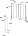
- FIG 10 a railing with several profiles 106 is shown, of which only some are provided with reference symbols for reasons of clarity.
- Two fastening devices 100 are fastened to some of the profiles 106. In this case, one of the fastening devices 100 is fastened in an upper region of the respective profile 106, while another of the fastening devices 100 is fastened in a lower region of the respective profile 106.
- the planking 200 is attached to the fastening devices 100 as previously described.
- one of the first legs 300 When inserted, one of the first legs 300 can still be fixed in the receiving area with a fixing means 500, so that removal upwards from the receiving area 600 is not easily possible. In addition, one or more fixed bearings can be produced quickly and easily. It is also possible for this work step to be carried out for several of the first legs 300.
Landscapes
- Engineering & Computer Science (AREA)
- Architecture (AREA)
- Civil Engineering (AREA)
- Structural Engineering (AREA)
- Clamps And Clips (AREA)
Description
- Die vorliegende Erfindung betrifft eine Befestigungsvorrichtung zur Befestigung eines Anbauteils an einem Profil eines Geländers gemäß Anspruch 1.
- Aus dem Stand der Technik gibt es verschiedene Möglichkeiten zur Befestigung eines Anbauteils an einem Profil eines Geländers. Das Anbauteil kann dabei beispielsweise eine Beplankung sein, die am Geländer befestigt werden soll. Die
JP 2000038770 A - Aus
DE 20 2013 003 652 U1 ist eine Vorrichtung zum Befestigen eines Elements an einem Stab einer Stabkonstruktion mit zwei Befestigungsteilen bekannt. Die Befestigungsteile sind unter formschlüssiger Umschließung des Stabes fest miteinander verbindbar. An einem oder an beiden Befestigungsteilen ist das zu befestigende Element anordenbar. - Demgegenüber liegt der vorliegenden Erfindung die Aufgabe zugrunde, eine einfacher an einem Geländer anzubringende Befestigungsvorrichtung zu schaffen. Außerdem soll ein System mit einer solchen Befestigungsvorrichtung und einem Geländer geschaffen werden.
- Diese Aufgabe wird durch eine Befestigungsvorrichtung gemäß Anspruch 1 und durch ein System gemäß Anspruch 11 gelöst. Ausführungsformen der Erfindung sind in den abhängigen Ansprüchen angegeben.
- Die Befestigungsvorrichtung umfasst ein erstes Greifmittel, ein zweites Greifmittel, ein Befestigungsmittel und ein Spreizmittel. Das erste Greifmittel umfasst ein erstes Greifelement. Das zweite Greifmittel umfasst ein zweites Greifelement. Das erste Greifmittel ist schwenkbar am zweiten Greifmittel gelagert. Das Spreizmittel ist dazu ausgebildet, eine Verschwenkung des ersten Greifmittels relativ zum zweiten Greifmittel auszulösen. Beispielsweise kann das Spreizmittel dazu ausgebildet sein, das zweite Greifelement weg vom ersten Greifelement zu bewegen.
- Ein Abstand zwischen dem ersten Greifelement und dem zweiten Greifelement wird bei der Verschwenkung verändert. Die Greifelemente sind in Hinterschneidungen einer Nut eines Profils einführbar und werden dort durch eine vom Spreizmittel ausgeübte Klemmkraft gehalten.
- Das zweite Greifmittel weist einen Aufnahmebereich für das Befestigungsmittel auf. Das Befestigungsmittel ist in den Aufnahmebereich einführbar. Das Befestigungsmittel ist außerdem dazu ausgebildet, am Anbauteil befestigt zu werden. Bei dem Anbauteil kann es sich beispielsweise um eine Beplankung handeln. Die Beplankung kann beispielsweise als Schichtstoffplatte, Glas, Holz oder Blech ausgebildet sein. Auch weiteres Zubehör wie beispielsweise ein Blumentopf oder eine Solarzelle können ein Anbauteil im Sinne dieser Beschreibung sein.
- Die Befestigungsvorrichtung lässt sich dafür nutzen, ein Anbauteil an einem bereits bestehenden Geländer ohne Modifikation des Geländers nachträglich zu befestigen. Die Befestigung ist dabei besonders einfach, da lediglich die Greifelemente in die Hinterschneidungen greifen müssen und das Anbauteil am Befestigungsmittel befestigt werden muss. Es werden keine Bohrungen am Geländer oder am Profil benötigt.
- Nach einer Ausführungsform der Erfindung kann das Befestigungsmittel im im Aufnahmebereich eingeführten Zustand, insbesondere kraftschlüssig, fixierbar sein. Hierunter wird im Rahmen dieser Beschreibung insbesondere verstanden, dass das Befestigungsmittel im fixierten Zustand nicht relativ zum zweiten Greifmittel bewegt werden kann. Die Fixierung ermöglicht somit eine besonders stabile Befestigung des Anbauteils an der Befestigungsvorrichtung.
- Nach einer Ausführungsform der Erfindung können das erste Greifmittel und/oder das zweite Greifmittel jeweils einstückig und/oder einteilig ausgebildet sein.
- Nach einer Ausführungsform der Erfindung kann das erste Greifmittel eine erste Ausnehmung aufweisen. Das Spreizmittel kann durch die erste Ausnehmung hindurch schraubbar sein. Zu diesem Zweck kann beispielsweise die erste Ausnehmung ein Innengewinde und das Spreizmittel ein Außengewinde aufweisen. Das Spreizmittel kann in einem ersten durch die erste Ausnehmung teilweise hindurch geschraubten Zustand am zweiten Greifmittel anliegen. Das Spreizmittel kann aus dem ersten Zustand weiter durch die erste Ausnehmung hindurch in einen zweiten Zustand schraubbar sein. Während des Schraubvorgangs vom ersten in den zweiten Zustand kann das Spreizmittel das zweite Greifmittel relativ zum ersten Greifmittel verschwenken. Es ist insbesondere möglich, dass das Spreizmittel während dieses Schraubvorgangs das zweite Greifmittel drückt.
- Nach einer Ausführungsform der Erfindung können das erste Greifmittel und das zweite Greifmittel formschlüssig ineinander greifen. Diese formschlüssige Verbindung kann insbesondere während der Verschwenkung des zweiten Greifmittels bestehen bleiben.
- Nach einer Ausführungsform der Erfindung kann das Befestigungsmittel im in den Aufnahmebereich eingeführten Zustand formschlüssig im Aufnahmebereich angeordnet sein. Dieser Formschluss kann insbesondere eine Bewegung des Befestigungsmittel in einer horizontalen Richtung und nach unten verhindern. Es kann allerdings möglich sein, dass der Formschluss durch eine Bewegung des Befestigungsmittels nach oben relativ zum Aufnahmebereich gelöst werden kann.
- Nach einer Ausführungsform der Erfindung kann das Befestigungsmittel einen ersten Schenkel und einen senkrecht zum ersten Schenkel angeordneten zweiten Schenkel umfassen. Der erste Schenkel kann im in den Aufnahmebereich eingeführten Zustand in den Aufnahmebereich hineinragen, während der zweite Schenkel auf Begrenzungen des Aufnahmebereichs aufliegt. Diese Form des Befestigungsmittels kann auch als in etwa L-förmig bezeichnet werden.
- Nach einer Ausführungsform der Erfindung kann die Befestigungsvorrichtung ein Befestigungselement umfassen. Das Befestigungsmittel kann eine zweite Ausnehmung aufweisen, in die das Befestigungselement, beispielsweise eine Schraube, einschraubbar ist. Die Einschraubbarkeit kann beispielsweise erreicht werden, indem die Ausnehmung ein Innengewinde aufweist. Alternativ hierzu kann auch direkt anschließend an die Ausnehmung eine Mutter mit Innengewinde am Befestigungsmittel, beispielsweise stoffschlüssig, befestigt sein.
- Alternativ hierzu kann das Befestigungselement formschlüssig in die zweite Ausnehmung eingesetzt werden. In diesem Fall kann das Befestigungselement als Niet ausgebildet sein.
- Das Anbauteil kann mit dem Befestigungselement im in der zweiten Ausnehmung eingeschraubten Zustand am Befestigungsmittel befestigbar sein. So kann das Anbauteil noch stabiler an der Befestigungsvorrichtung befestigt werden.
- Nach einer Ausführungsform der Erfindung kann die zweite Ausnehmung im zweiten Schenkel angeordnet sein.
- Nach einer Ausführungsform der Erfindung kann der erste Schenkel des Befestigungsmittels einen konisch zu einem Ende hin zulaufenden Bereich aufweisen. Mit diesem Bereich kann der erste Schenkel in den Aufnahmebereich einführbar sein. Die konische Form hat insbesondere den Vorteil, dass der erste Schenkel einfacher in den Aufnahmebereich einführbar ist.
- Das System gemäß Anspruch 11 umfasst ein Geländer mit mindestens einem Profil und einer Befestigungsvorrichtung nach einer Ausführungsform der Erfindung. Das Profil kann beispielsweise in einer vertikalen Richtung verlaufen. Dies kann bedeuten, dass es seine größte Ausdehnung in der vertikalen Richtung aufweist. Hierunter wird im Rahmen dieser Beschreibung insbesondere verstanden, dass das Profil senkrecht zu einer Oberfläche eines Bauteils verläuft, an dem das Geländer befestigt ist. Es ist allerdings auch möglich, dass das Profil einen Winkel von weniger als 90° mit der Oberfläche des Bauteils einschließt. In diesem Fall kann das Profil als geneigt bezeichnet werden. Das Bauteil kann beispielsweise ein Balkon, ein französischer Balkon, eine Brüstung oder eine Treppe sein.
- Das Profil weist eine Nut mit zwei Hinterschneidungen auf. Die Nut und die Hinterschneidungen erstrecken sich jeweils in einer Längsrichtung des Profils. Es ist insbesondere möglich, dass sich die Längsrichtungen der Nut und der Hinterschneidungen parallel zur Längsrichtung des Profils erstreckt. Unter der Längsrichtung wird dabei die Richtung verstanden, in der das Profil bzw. die Nut bzw. die Hinterschneidungen seine bzw. ihre größte Ausdehnung aufweist. Insbesondere können sich die Nut und die Hinterschneidungen parallel zueinander erstrecken. Die Nut kann auch als T-Nut bezeichnet werden, da ihre Form im Querschnitt T-ähnlich sein kann.
- Die Nut kann beispielsweise auch in das Profil gefräst sein. Im Rahmen dieser Beschreibung soll eine längliche Ausfräsung ebenfalls als Nut verstanden werden. Dies gilt insbesondere für eine T-förmige Ausfräsung.
- Die Befestigungsvorrichtung ist am Profil befestigbar, indem das erste Greifelement und das zweite Greifelement jeweils hinter eine der Hinterschneidungen greifen und mittels des Spreizmittels dort, insbesondere kraftschlüssig, gehalten sind.
- Nach einer Ausführungsform der Erfindung kann das Spreizmittel auf die Greifelemente eine Klemmkraft ausüben, wenn das Spreizmittel die Greifelemente hinter den Hinterschneidungen hält.
- Nach einer Ausführungsform der Erfindung kann das System das Anbauteil umfassen. Das Anbauteil kann am Befestigungsmittel, insbesondere direkt, befestigt sein. Dies kann beispielsweise mit dem Befestigungselement erfolgen, das als Schraube ausgebildet sein kann.
- Nach einer Ausführungsform der Erfindung kann das System mehrere Befestigungsvorrichtungen nach einer Ausführungsform der Erfindung umfassen. Das Geländer kann mehrere Profile umfassen. Die Befestigungsvorrichtungen können an verschiedenen der Profile befestigt sein. Bei mehreren der Befestigungsvorrichtungen kann das Befestigungsmittel in einer Richtung frei beweglich sein. Diese Richtung kann insbesondere oben sein. Zumindest eines der Befestigungsmittel kann kraftschlüssig im Aufnahmebereich fixiert sein. Es ist insbesondere möglich, dass dieses Befestigungsmittel unbeweglich relativ zum Aufnahmebereich ist. Die in einer Richtung beweglichen Befestigungsmittel können als Loslager bezeichnet werden. Das fixierte Befestigungsmittel kann als Festlager bezeichnet werden.
- Nach einer Ausführungsform der Erfindung kann das System ein Bauteil umfassen, an dem das Geländer befestigt sein kann. Das Bauteil kann beispielsweise ein Balkon, ein französischer Balkon, eine Brüstung oder eine Treppe sein.
- Weitere Merkmale und Vorteile der vorliegenden Erfindung werden deutlich anhand der nachfolgenden Beschreibung bevorzugter Ausführungsbeispiele unter Bezugnahme auf die beiliegenden Abbildungen. Dabei werden für gleiche oder ähnliche Bauteile und für Bauteile mit gleichen oder ähnlichen Funktionen dieselben Bezugszeichen verwendet. Darin zeigen:
- Fig. 1
- eine schematische perspektivische Ansicht einer Befestigungsvorrichtung nach einer Ausführungsform der Erfindung, befestigt an einem Profil eines Geländers;
- Fig. 2
- eine schematische Draufsicht auf die Befestigungsvorrichtung aus
Fig. 1 ; - Fig. 3
- eine Schnittansicht entlang der Linie III-III aus
Fig. 2 ; - Fig. 4
- eine schematische Seitenansicht der Ausführungsform aus
Fig. 1 ; - Fig. 5A
- eine Schnittansicht entlang der Linie V-V aus
Fig. 4 mit Fixierung des Befestigungsmittels; - Fig. 5B
- eine Schnittansicht entlang der Linie V-V aus
Fig. 4 ohne Fixierung des Befestigungsmittels; - Fig. 6
- eine schematische Draufsicht auf eine Befestigungsvorrichtung nach einer Ausführungsform der Erfindung ohne eingesetztes Befestigungsmittel;
- Fig. 7
- eine schematische perspektivische Ansicht der Ausführungsform aus
Fig. 1 ; - Fig. 8
- eine schematische perspektivische Ansicht eines Befestigungsmittels nach einer Ausführungsform der Erfindung;
- Fig. 9
- eine schematische perspektivische Ansicht eines ersten und zweiten Greifmittels nach einer Ausführungsform der Erfindung;
- Fig. 10
- eine schematische perspektivische Ansicht eines Systems nach einer Ausführungsform der Erfindung mit einer an mehreren Profilen befestigten Beplankung;
- Fig. 11
- eine schematische seitliche Ansicht des Systems aus
Fig. 10 mit abgenommener Beplankung. - Die Befestigungsvorrichtung 100 umfasst ein erstes Greifmittel 101, ein zweites Greifmittel 102, ein Befestigungsmittel 103 und ein Befestigungselement 105. Das erste Greifmittel 101 und das zweite Greifmittel 102 sind relativ zueinander um eine Schwenkachse verschwenkbar. Die Befestigungsvorrichtung 100 ist an einem Profil 106 mit einer in Längsrichtung verlaufenden Nut 107 befestigt. Die Nut 107 weist zwei Hinterschneidungen auf, in die Greifelemente der Greifmittel 101 und 102 hineingreifen. Aufgrund der Hinterschneidungen weist die Nut 107 in etwa eine T-Form auf und kann daher auch als T-Nut bezeichnet werden.
- Das erste Greifmittel 101 weist eine erste Ausnehmung auf, durch die ein Spreizmittel 201 hindurch geschraubt ist. Das Spreizmittel 201 übt eine Kraft auf das zweite Greifmittel 102 aus, sodass die Greifelemente kraftschlüssig in den Hinterschneidungen der Nut 107 befestigt sind. Die Befestigungsvorrichtung 100 kann in variabler Höhe am Profil 106 befestigt werden, da die beiden Greifmittel 101 und 102 entlang der Nut 107 verschiebbar und an jeder Position mittels des Spreizmittels 201 fixierbar sind.
- Das zweite Greifmittel 102 weist einen Aufnahmebereich für ein Befestigungsmittel 103 auf. Ein erster Schenkel 300 des Befestigungsmittels 103 ragt dabei in den Aufnahmebereich hinein, während ein zweiter Schenkel 104 auf einer Begrenzung des Aufnahmebereichs aufliegt. Das Befestigungsmittel ist so formschlüssig im zweiten Greifmittel 102 gelagert und kann ohne Fixierung nach oben aus dem Aufnahmebereich entnommen werden, während eine seitliche Bewegung oder eine Bewegung nach unten blockiert ist.
- Im zweiten Schenkel 104 ist das Befestigungselement 105 eingeschraubt. Dies dient - wie beispielsweise
Figur 2 zu entnehmen ist - der Befestigung einer Beplankung 200 an der Befestigungsvorrichtung 100. Alternativ kann das Befestigungselement 105 auch als Niet ausgebildet sein und formschlüssig im zweiten Schenkel 104 eingesetzt sein. Der Niet kann beispielsweise aus Kunststoff sein. Am zweiten Schenkel 104 ist ein Kunststofflager 108 angeordnet, durch das das Befestigungselement 105 im eingeschraubten oder eingesetzten Zustand hindurchragt. - Die Beplankung 200 kann beispielsweise am Befestigungsmittel 103 befestigt werden. Die Beplankung 200 kann beispielsweise als Schichtstoffplatte, Glas, Holz oder Blech ausgebildet sein. Die Greifmittel 101 und 102 werden unter Verwendung des Spreizmittels 201 in der Nut 107 des Profils 106 befestigt. Nachdem dies erfolgt ist, kann die Beplankung 200 einfach am Profil 106 befestigt werden, indem der erste Schenkel 300 des Befestigungsmittels 103 in den Aufnahmebereich des zweiten Greifmittels 102 eingesetzt wird.
- Wie
Figur 3 zu entnehmen ist, weist der erste Schenkel 300 ein konisch zu einem Ende hin zulaufenden Bereich 301 auf, mit dem er in dem Aufnahmebereich des zweiten Greifmittels 102 eingesetzt ist. Dieser konisch zulaufende Bereich 301 ist besonders vorteilhaft beim Einsetzen des Befestigungsmittels 104 in den Aufnahmebereich, insbesondere da die Beplankung 200 für einen Benutzer relativ schwer und unhandlich sein kann. Vorzugsweise wird die Beplankung unter Verwendung mehrerer Befestigungsvorrichtungen an mehreren Profilen befestigt. Bei dieser Vorgehensweise sind die konischen Bereiche 301 der ersten Schenkel 300 besonders vorteilhaft, um alle ersten Schenkel 300 in die zugehörigen Aufnahmebereiche einzuführen. - Zwischen dem zweiten Greifmittel 102 und dem Befestigungsmittel 103 ist ein Federelement 302 angeordnet. Das Federelement 302 bietet eine zusätzliche Rastfunktion. Außerdem vermindert das Federelement 302 unerwünschte Geräusche, die beispielsweise entstehen können, wenn zwischen dem zweiten Greifmittel 102 und dem Befestigungsmittel 103 Spiel vorhanden ist und das zweite Greifmittel 102 immer wieder in Kontakt mit dem Befestigungsmittel 103 gelangt.
- Das zweite Greifmittel 102 weist außerdem eine Ausnehmung 400 auf, durch die ein Fixierungsmittel 500 hindurch schraubbar ist, um den ersten Schenkel 300 im Aufnahmebereich zu fixieren. Im mittels des Fixierungsmittels 500 fixierten Zustand lässt sich der erste Schenkel 300 nicht mehr relativ zum zweiten Greifmittel 102 bewegen. Ohne Fixierungsmittel 500 ist hingegen eine Entnahme des ersten Schenkels 300 nach oben aus dem Aufnahmebereich möglich. Das Fixierungsmittel 500 kann beispielsweise eine Schraube sein.
- Eine Scheibe 501 ist in einen Schlitz des zweiten Greifmittels 102 eingesetzt, gegen die das Fixierungsmittel 500 den ersten Schenkel 300 drückt. Der Schlitz ist dabei direkt benachbart zum Aufnahmebereich angeordnet. Dies hat den Vorteil, dass bei gleichzeitig verwendeten anderen Befestigungsvorrichtungen 100 zur Befestigung des gleichen Anbauteils die jeweiligen ersten Schenkel 300 nicht ebenfalls fixiert werden. So kann die Befestigungsvorrichtung 100 gemäß
Figur 5A als Festlager verwendet werden, während die anderen Befestigungsvorrichtungen 100 als Loslager verwendet werden können. Solch ein Loslager ist beispielsweise inFigur 5B dargestellt. Die Scheibe 501 kann beispielsweise auch als Unterlegscheibe, Distanzscheibe oder Distanzring bezeichnet werden. - In
Figur 6 ist der Aufnahmebereich 600 besonders gut zu erkennen, in den der erste Schenkel 300 einführbar ist. - In
Figur 7 ist die erste Ausnehmung 700 im ersten Greifmittel 101 dargestellt, durch die das Spreizmittel 201 hindurch geschraubt wird, um die Greifelemente in den Hinterschneidungen der Nut 107 einzuklemmen. - In
Figur 8 ist die zweite Ausnehmung 800 im zweiten Schenkel 104 des Befestigungsmittels 103 dargestellt, in die das Befestigungselement 105 zur Befestigung der Beplankung 200 an der Befestigungsvorrichtung 100 eingeschraubt werden kann. Die Ausnehmung 800 kann zu diesem Zweck ein Innengewinde aufweisen. Alternativ oder zusätzlich kann auch eine Mutter in die Ausnehmung 800 eingesetzt werden. - In
Figur 9 ist das erste Greifelement 900 des ersten Greifmittels 101 dargestellt, das in eine der Hinterschneidungen der Nut 107 greift. Außerdem ist das zweite Greifelement 901 des zweiten Greifmittels 102 dargestellt, das in die andere der Hinterschneidungen der Nut 107 greift und so die Befestigungsvorrichtung einfach und sicher am Profil 106 befestigt. - In
Figur 10 ist ein Geländer mit mehreren Profilen 106 dargestellt, von denen aus Gründen der Übersichtlichkeit nur einige mit Bezugszeichen versehen sind. An einigen der Profile 106 sind jeweils zwei Befestigungsvorrichtungen 100 befestigt. Dabei ist jeweils eine der Befestigungsvorrichtungen 100 in einem oberen Bereich des jeweiligen Profils 106 befestigt, während eine andere der Befestigungsvorrichtungen 100 in einem unteren Bereich des jeweiligen Profils 106 befestigt ist. - An den Befestigungsvorrichtungen 100 ist wie in zuvor beschriebener Weise die Beplankung 200 befestigt.
- Aus
Figur 11 kann die Montage der Beplankung 200 an den Profilen 106 nachvollzogen werden. Die Befestigungsmittel 103 sind an der Beplankung mit den Befestigungselementen 105 befestigt. Mehrere zweite Greifmittel 102 mit jeweils einem Aufnahmebereich 600 sind an mehreren Profilen 106 befestigt. Zur Montage werden nun die ersten Schenkel 300 der Befestigungsmittel 103 in die Aufnahmebereiche 600 eingeführt. Dieser Schritt ist inFigur 11 mit einer teilweise gestrichelten Linie verdeutlicht. Hilfreich sind hierbei die konischen Bereiche 301 der ersten Schenkel 300. - Im eingesetzten Zustand kann einer der ersten Schenkel 300 noch im Aufnahmebereich mit einem Fixierungsmittel 500 fixiert werden, sodass eine Entnahme nach oben aus dem Aufnahmebereich 600 heraus nicht ohne Weiteres möglich ist. Außerdem lässt bzw. lassen sich so schnell und einfach ein oder mehrere Festlager herstellen. Es ist auch möglich, dass dieser Arbeitsschritt für mehrere der ersten Schenkel 300 durchgeführt wird.
Claims (15)
- Befestigungsvorrichtung (100) zur Befestigung eines Anbauteils (200) an einem Profil (106) eines Geländers, umfassend ein erstes Greifmittel (101), ein zweites Greifmittel (102), ein Befestigungsmittel (103) und ein Spreizmittel (201), wobei das erste Greifmittel (101) ein erstes Greifelement (900) und das zweite Greifmittel (102) ein zweites Greifelement (901) umfasst, wobei das erste Greifmittel (101) am zweiten Greifmittel (102) schwenkbar gelagert ist, wobei das Spreizmittel (201) dazu ausgebildet ist, eine Verschwenkung des ersten Greifmittels (101) relativ zum zweiten Greifmittel (102) auszulösen, wobei ein Abstand zwischen dem ersten Greifelement (900) und dem zweiten Greifelement (901) bei der Verschwenkung verändert wird, wobei das zweite Greifmittel (102) einen Aufnahmebereich (600) für das Befestigungsmittel (103) umfasst, wobei das Befestigungsmittel (103) in den Aufnahmebereich (600) einführbar ist, und wobei das Befestigungsmittel (103) dazu ausgebildet ist, am Anbauteil (200) befestigt zu werden, dadurch gekennzeichnet, dass die Greifelemente in Hinterschneidungen einer Nut eines Profils einführbar sind und dort durch eine vom Spreizmittel ausgeübte Klemmkraft gehalten werden.
- Befestigungsvorrichtung (100) nach Anspruch 1, dadurch gekennzeichnet, dass das Befestigungsmittel (103) im im Aufnahmebereich (600) eingeführten Zustand fixierbar ist.
- Befestigungsvorrichtung (100) nach einem der vorherigen Ansprüche, dadurch gekennzeichnet, dass das erste Greifmittel (101) und/oder das zweite Greifmittel (102) jeweils einstückig und/oder einteilig ausgebildet sind.
- Befestigungsvorrichtung (100) nach einem der vorherigen Ansprüche, dadurch gekennzeichnet, dass das erste Greifmittel (101) eine erste Ausnehmung (400) aufweist, wobei das Spreizmittel (201) durch die erste Ausnehmung (400) hindurch schraubbar ist, wobei das Spreizmittel (201) in einem ersten durch die erste Ausnehmung (400) teilweise hindurch geschraubten Zustand am zweiten Greifmittel (102) anliegt, wobei das Spreizmittel (201) aus dem ersten Zustand weiter durch die erste Ausnehmung (400) hindurch in einen zweiten Zustand schraubbar ist, wobei das Spreizmittel (201) während des Schraubvorgangs vom ersten in den zweiten Zustand das zweite Greifmittel (102) relativ zum ersten Greifmittel (101) verschwenkt.
- Befestigungsvorrichtung (100) nach einem der vorherigen Ansprüche, dadurch gekennzeichnet, dass das erste Greifmittel (101) und das zweite Greifmittel (102) formschlüssig ineinandergreifen.
- Befestigungsvorrichtung (100) nach einem der vorherigen Ansprüche, dadurch gekennzeichnet, dass das Befestigungsmittel (103) im in den Aufnahmebereich (600) eingeführten Zustand formschlüssig im Aufnahmebereich (600) angeordnet ist.
- Befestigungsvorrichtung (100) nach dem vorherigen Anspruch, dadurch gekennzeichnet, dass das Befestigungsmittel (103) einen ersten Schenkel (300) und einen senkrecht zum ersten Schenkel (300) angeordneten zweiten Schenkel (104) umfasst, wobei der erste Schenkel (300) im in den Aufnahmebereich (600) eingeführten Zustand in den Aufnahmebereich (600) hineinragt, während der zweite Schenkel (104) auf Begrenzungen des Aufnahmebereichs (600) aufliegt.
- Befestigungsvorrichtung (100) nach dem vorherigen Anspruch, dadurch gekennzeichnet, dass der erste Schenkel (300) des Befestigungsmittels (103) einen konisch zu einem Ende hin zulaufenden Bereich (301) aufweist, mit dem er in den Aufnahmebereich (600) einführbar ist.
- Befestigungsvorrichtung (100) nach einem der vorherigen Ansprüche, dadurch gekennzeichnet, dass die Befestigungsvorrichtung (100) ein Befestigungselement (105) umfasst, wobei das Befestigungsmittel (103) eine zweite Ausnehmung (800) aufweist, in die das Befestigungselement (105) einschraubbar ist, wobei das Anbauteil (200) mit dem Befestigungselement (105) im in der zweiten Ausnehmung (800) eingeschraubten Zustand am Befestigungsmittel (103) befestigbar ist.
- Befestigungsvorrichtung (100) nach dem vorherigen Anspruch in Abhängigkeit von Anspruch 7 oder 8, dadurch gekennzeichnet, dass die zweite Ausnehmung (800) im zweiten Schenkel (104) angeordnet ist.
- System, umfassend ein Geländer mit mindestens einem Profil (106) und mindestens eine Befestigungsvorrichtung (100) nach einem der vorherigen Ansprüche, wobei das Profil (106) eine Nut (107) mit zwei Hinterschneidungen aufweist, wobei sich die Nut (107) und die Hinterschneidungen jeweils in einer Längsrichtung des Profils (106) erstrecken, wobei die Befestigungsvorrichtung (100) am Profil (106) befestigbar ist, indem das erste Greifelement (900) und das zweite Greifelement (901) jeweils hinter eine der Hinterschneidungen greifen und mittels des Spreizmittels (201) dort gehalten sind.
- System nach dem vorherigen Anspruch, dadurch gekennzeichnet, dass das Spreizmittel (201) auf die Greifelemente (900; 901) eine Klemmkraft ausübt, wenn das Spreizmittel (201) die Greifelemente (900; 901) hinter den Hinterschneidungen hält.
- System nach einem der beiden vorherigen Ansprüche, dadurch gekennzeichnet, dass das System das Anbauteil (200) umfasst, wobei das Anbauteil (200) am Befestigungsmittel (103) befestigt ist.
- System nach einem der drei vorherigen Ansprüche, dadurch gekennzeichnet, dass das System mehrere Befestigungsvorrichtungen (100) nach einem der Ansprüche 1 bis 9 umfasst, wobei das Geländer mehrere Profile (106) umfasst, wobei die Befestigungsvorrichtungen (100) an verschiedenen der Profile (106) befestigt sind, wobei bei mehreren der Befestigungsvorrichtungen (100) das Befestigungsmittel (103) in einer Richtung frei beweglich ist, und wobei zumindest eines der Befestigungsmittel (103) kraftschlüssig im Aufnahmebereich (600) fixiert ist.
- System nach einem der vier vorherigen Ansprüche, dadurch gekennzeichnet, dass das System ein Bauteil umfasst, wobei das Geländer am Bauteil befestigt ist.
Priority Applications (1)
| Application Number | Priority Date | Filing Date | Title |
|---|---|---|---|
| EP20189670.1A EP3951114B1 (de) | 2020-08-05 | 2020-08-05 | Befestigungsvorrichtung |
Applications Claiming Priority (1)
| Application Number | Priority Date | Filing Date | Title |
|---|---|---|---|
| EP20189670.1A EP3951114B1 (de) | 2020-08-05 | 2020-08-05 | Befestigungsvorrichtung |
Publications (2)
| Publication Number | Publication Date |
|---|---|
| EP3951114A1 EP3951114A1 (de) | 2022-02-09 |
| EP3951114B1 true EP3951114B1 (de) | 2024-10-09 |
Family
ID=71950552
Family Applications (1)
| Application Number | Title | Priority Date | Filing Date |
|---|---|---|---|
| EP20189670.1A Active EP3951114B1 (de) | 2020-08-05 | 2020-08-05 | Befestigungsvorrichtung |
Country Status (1)
| Country | Link |
|---|---|
| EP (1) | EP3951114B1 (de) |
Families Citing this family (2)
| Publication number | Priority date | Publication date | Assignee | Title |
|---|---|---|---|---|
| CN118601136B (zh) * | 2024-08-09 | 2024-10-01 | 中国建筑第五工程局有限公司 | 一种高安全性错层悬挑阳台结构及其组装使用方法 |
| EP4729715A1 (de) * | 2024-10-17 | 2026-04-22 | Big Jurij GmbH | Montagehilfe und montageverfahren zur montage |
Family Cites Families (5)
| Publication number | Priority date | Publication date | Assignee | Title |
|---|---|---|---|---|
| JP3652514B2 (ja) * | 1998-07-22 | 2005-05-25 | 文化シヤッター株式会社 | 建材の取付構造およびその取付具 |
| DE29814129U1 (de) * | 1998-08-06 | 1999-02-18 | Lemcke, Klaus, 61276 Weilrod | Klemmhalter zum Befestigen von Platten feglicher Art an Balkon- oder Treppengeländer |
| FR2953542A1 (fr) * | 2009-12-07 | 2011-06-10 | Dani Alu | Dispositif de fixation temporaire d’un filet de securite sur un montant de garde-corps |
| DE202011003253U1 (de) * | 2011-02-25 | 2011-05-19 | gusto products & services GmbH, 51063 | Vorrichtung zur Halterung von Gegenständen an einem Balkongeländer |
| DE202013003652U1 (de) * | 2013-04-18 | 2013-04-29 | Klaus Brenk | Befestigungsvorrichtung |
-
2020
- 2020-08-05 EP EP20189670.1A patent/EP3951114B1/de active Active
Also Published As
| Publication number | Publication date |
|---|---|
| EP3951114A1 (de) | 2022-02-09 |
Similar Documents
| Publication | Publication Date | Title |
|---|---|---|
| DE2618442C2 (de) | Stütze für ein Geländer oder dergleichen | |
| DE102013109845A1 (de) | Lager für eine Unterkonstruktion, beispielsweise einer Terrasse | |
| EP3623722B1 (de) | Dachhaken | |
| EP3623721B1 (de) | Dachhaken | |
| DE102007013438B4 (de) | Blumenkastenhalterung mit einer Klemmvorrichtung | |
| EP2372269A2 (de) | Verbindungsvorrichtung und Profilanordnung | |
| EP3951114A1 (de) | Befestigungsvorrichtung | |
| DE2910325A1 (de) | Halter fuer schutzgelaender | |
| DE202013005582U1 (de) | System umfassend ein Trägerbauteil | |
| DE202016100920U1 (de) | Vorrichtung zur Anordnung einer auskragenden Struktur | |
| DE102016124988B4 (de) | Beschlag und Verfahren für das Verlegen von Terrassendielen | |
| DE102011000196B4 (de) | Befestigungsvorrichtung | |
| DE19604174A1 (de) | Verfahren und Vorrichtung zur Befestigung von Geländerpfosten an einer Betonplatte | |
| EP3336275B1 (de) | Markisentuch-fixier- und -führungseinrichtung | |
| DE102015118360A1 (de) | Halterung für plattenelemente von brüstungen, geländern und dergleichen | |
| DE29516040U1 (de) | Tragstütze sowie Tragvorrichtung mit wenigstens vier im Abstand zueinander angeordneten Tragstützen | |
| DE4401138C2 (de) | Verfahren zur Herstellung einer Befestigungsvorrichtung für Balkongeländer | |
| AT527299B1 (de) | Absturzsicherungselement | |
| DE3940626C2 (de) | Verfahren und Vorrichtung zum Befestigen eines Balkonbretts | |
| EP3786391B1 (de) | Haltevorrichtung zum lösbaren befestigen an einem gebäudedach und absturzsicherung mit einer solchen haltevorrichtung | |
| EP0731235A1 (de) | Montagevorrichtung für einen Sonnenschutz | |
| DE9210602U1 (de) | Befestigungselement für Verkleidungselemente | |
| DE29810308U1 (de) | Vorrichtung zur Befestigung einer Fülltafel | |
| DE9419270U1 (de) | Befestigungsvorrichtung für Balkongeländer | |
| EP4481298A1 (de) | Modulklemme zum befestigen mindestens eines solarmoduls |
Legal Events
| Date | Code | Title | Description |
|---|---|---|---|
| PUAI | Public reference made under article 153(3) epc to a published international application that has entered the european phase |
Free format text: ORIGINAL CODE: 0009012 |
|
| STAA | Information on the status of an ep patent application or granted ep patent |
Free format text: STATUS: THE APPLICATION HAS BEEN PUBLISHED |
|
| AK | Designated contracting states |
Kind code of ref document: A1 Designated state(s): AL AT BE BG CH CY CZ DE DK EE ES FI FR GB GR HR HU IE IS IT LI LT LU LV MC MK MT NL NO PL PT RO RS SE SI SK SM TR |
|
| STAA | Information on the status of an ep patent application or granted ep patent |
Free format text: STATUS: REQUEST FOR EXAMINATION WAS MADE |
|
| 17P | Request for examination filed |
Effective date: 20220809 |
|
| RBV | Designated contracting states (corrected) |
Designated state(s): AL AT BE BG CH CY CZ DE DK EE ES FI FR GB GR HR HU IE IS IT LI LT LU LV MC MK MT NL NO PL PT RO RS SE SI SK SM TR |
|
| GRAP | Despatch of communication of intention to grant a patent |
Free format text: ORIGINAL CODE: EPIDOSNIGR1 |
|
| STAA | Information on the status of an ep patent application or granted ep patent |
Free format text: STATUS: GRANT OF PATENT IS INTENDED |
|
| INTG | Intention to grant announced |
Effective date: 20240111 |
|
| GRAS | Grant fee paid |
Free format text: ORIGINAL CODE: EPIDOSNIGR3 |
|
| GRAA | (expected) grant |
Free format text: ORIGINAL CODE: 0009210 |
|
| STAA | Information on the status of an ep patent application or granted ep patent |
Free format text: STATUS: THE PATENT HAS BEEN GRANTED |
|
| AK | Designated contracting states |
Kind code of ref document: B1 Designated state(s): AL AT BE BG CH CY CZ DE DK EE ES FI FR GB GR HR HU IE IS IT LI LT LU LV MC MK MT NL NO PL PT RO RS SE SI SK SM TR |
|
| REG | Reference to a national code |
Ref country code: CH Ref legal event code: EP |
|
| REG | Reference to a national code |
Ref country code: DE Ref legal event code: R096 Ref document number: 502020009413 Country of ref document: DE |
|
| REG | Reference to a national code |
Ref country code: IE Ref legal event code: FG4D Free format text: LANGUAGE OF EP DOCUMENT: GERMAN |
|
| REG | Reference to a national code |
Ref country code: LT Ref legal event code: MG9D |
|
| REG | Reference to a national code |
Ref country code: NL Ref legal event code: MP Effective date: 20241009 |
|
| PG25 | Lapsed in a contracting state [announced via postgrant information from national office to epo] |
Ref country code: NL Free format text: LAPSE BECAUSE OF FAILURE TO SUBMIT A TRANSLATION OF THE DESCRIPTION OR TO PAY THE FEE WITHIN THE PRESCRIBED TIME-LIMIT Effective date: 20241009 |
|
| PG25 | Lapsed in a contracting state [announced via postgrant information from national office to epo] |
Ref country code: NL Free format text: LAPSE BECAUSE OF FAILURE TO SUBMIT A TRANSLATION OF THE DESCRIPTION OR TO PAY THE FEE WITHIN THE PRESCRIBED TIME-LIMIT Effective date: 20241009 |
|
| PG25 | Lapsed in a contracting state [announced via postgrant information from national office to epo] |
Ref country code: IS Free format text: LAPSE BECAUSE OF FAILURE TO SUBMIT A TRANSLATION OF THE DESCRIPTION OR TO PAY THE FEE WITHIN THE PRESCRIBED TIME-LIMIT Effective date: 20250209 Ref country code: PT Free format text: LAPSE BECAUSE OF FAILURE TO SUBMIT A TRANSLATION OF THE DESCRIPTION OR TO PAY THE FEE WITHIN THE PRESCRIBED TIME-LIMIT Effective date: 20250210 Ref country code: HR Free format text: LAPSE BECAUSE OF FAILURE TO SUBMIT A TRANSLATION OF THE DESCRIPTION OR TO PAY THE FEE WITHIN THE PRESCRIBED TIME-LIMIT Effective date: 20241009 |
|
| PG25 | Lapsed in a contracting state [announced via postgrant information from national office to epo] |
Ref country code: FI Free format text: LAPSE BECAUSE OF FAILURE TO SUBMIT A TRANSLATION OF THE DESCRIPTION OR TO PAY THE FEE WITHIN THE PRESCRIBED TIME-LIMIT Effective date: 20241009 |
|
| PG25 | Lapsed in a contracting state [announced via postgrant information from national office to epo] |
Ref country code: BG Free format text: LAPSE BECAUSE OF FAILURE TO SUBMIT A TRANSLATION OF THE DESCRIPTION OR TO PAY THE FEE WITHIN THE PRESCRIBED TIME-LIMIT Effective date: 20241009 |
|
| PG25 | Lapsed in a contracting state [announced via postgrant information from national office to epo] |
Ref country code: ES Free format text: LAPSE BECAUSE OF FAILURE TO SUBMIT A TRANSLATION OF THE DESCRIPTION OR TO PAY THE FEE WITHIN THE PRESCRIBED TIME-LIMIT Effective date: 20241009 |
|
| PG25 | Lapsed in a contracting state [announced via postgrant information from national office to epo] |
Ref country code: NO Free format text: LAPSE BECAUSE OF FAILURE TO SUBMIT A TRANSLATION OF THE DESCRIPTION OR TO PAY THE FEE WITHIN THE PRESCRIBED TIME-LIMIT Effective date: 20250109 |
|
| PG25 | Lapsed in a contracting state [announced via postgrant information from national office to epo] |
Ref country code: GR Free format text: LAPSE BECAUSE OF FAILURE TO SUBMIT A TRANSLATION OF THE DESCRIPTION OR TO PAY THE FEE WITHIN THE PRESCRIBED TIME-LIMIT Effective date: 20250110 Ref country code: LV Free format text: LAPSE BECAUSE OF FAILURE TO SUBMIT A TRANSLATION OF THE DESCRIPTION OR TO PAY THE FEE WITHIN THE PRESCRIBED TIME-LIMIT Effective date: 20241009 |
|
| PG25 | Lapsed in a contracting state [announced via postgrant information from national office to epo] |
Ref country code: PL Free format text: LAPSE BECAUSE OF FAILURE TO SUBMIT A TRANSLATION OF THE DESCRIPTION OR TO PAY THE FEE WITHIN THE PRESCRIBED TIME-LIMIT Effective date: 20241009 |
|
| PG25 | Lapsed in a contracting state [announced via postgrant information from national office to epo] |
Ref country code: RS Free format text: LAPSE BECAUSE OF FAILURE TO SUBMIT A TRANSLATION OF THE DESCRIPTION OR TO PAY THE FEE WITHIN THE PRESCRIBED TIME-LIMIT Effective date: 20250109 |
|
| PG25 | Lapsed in a contracting state [announced via postgrant information from national office to epo] |
Ref country code: SM Free format text: LAPSE BECAUSE OF FAILURE TO SUBMIT A TRANSLATION OF THE DESCRIPTION OR TO PAY THE FEE WITHIN THE PRESCRIBED TIME-LIMIT Effective date: 20241009 |
|
| PG25 | Lapsed in a contracting state [announced via postgrant information from national office to epo] |
Ref country code: DK Free format text: LAPSE BECAUSE OF FAILURE TO SUBMIT A TRANSLATION OF THE DESCRIPTION OR TO PAY THE FEE WITHIN THE PRESCRIBED TIME-LIMIT Effective date: 20241009 |
|
| REG | Reference to a national code |
Ref country code: DE Ref legal event code: R097 Ref document number: 502020009413 Country of ref document: DE |
|
| PG25 | Lapsed in a contracting state [announced via postgrant information from national office to epo] |
Ref country code: EE Free format text: LAPSE BECAUSE OF FAILURE TO SUBMIT A TRANSLATION OF THE DESCRIPTION OR TO PAY THE FEE WITHIN THE PRESCRIBED TIME-LIMIT Effective date: 20241009 |
|
| PG25 | Lapsed in a contracting state [announced via postgrant information from national office to epo] |
Ref country code: RO Free format text: LAPSE BECAUSE OF FAILURE TO SUBMIT A TRANSLATION OF THE DESCRIPTION OR TO PAY THE FEE WITHIN THE PRESCRIBED TIME-LIMIT Effective date: 20241009 |
|
| PG25 | Lapsed in a contracting state [announced via postgrant information from national office to epo] |
Ref country code: SK Free format text: LAPSE BECAUSE OF FAILURE TO SUBMIT A TRANSLATION OF THE DESCRIPTION OR TO PAY THE FEE WITHIN THE PRESCRIBED TIME-LIMIT Effective date: 20241009 |
|
| PG25 | Lapsed in a contracting state [announced via postgrant information from national office to epo] |
Ref country code: CZ Free format text: LAPSE BECAUSE OF FAILURE TO SUBMIT A TRANSLATION OF THE DESCRIPTION OR TO PAY THE FEE WITHIN THE PRESCRIBED TIME-LIMIT Effective date: 20241009 |
|
| PG25 | Lapsed in a contracting state [announced via postgrant information from national office to epo] |
Ref country code: IT Free format text: LAPSE BECAUSE OF FAILURE TO SUBMIT A TRANSLATION OF THE DESCRIPTION OR TO PAY THE FEE WITHIN THE PRESCRIBED TIME-LIMIT Effective date: 20241009 |
|
| PLBE | No opposition filed within time limit |
Free format text: ORIGINAL CODE: 0009261 |
|
| STAA | Information on the status of an ep patent application or granted ep patent |
Free format text: STATUS: NO OPPOSITION FILED WITHIN TIME LIMIT |
|
| PG25 | Lapsed in a contracting state [announced via postgrant information from national office to epo] |
Ref country code: SE Free format text: LAPSE BECAUSE OF FAILURE TO SUBMIT A TRANSLATION OF THE DESCRIPTION OR TO PAY THE FEE WITHIN THE PRESCRIBED TIME-LIMIT Effective date: 20241009 |
|
| 26N | No opposition filed |
Effective date: 20250710 |
|
| PGFP | Annual fee paid to national office [announced via postgrant information from national office to epo] |
Ref country code: DE Payment date: 20250831 Year of fee payment: 6 |
|
| PGFP | Annual fee paid to national office [announced via postgrant information from national office to epo] |
Ref country code: GB Payment date: 20250820 Year of fee payment: 6 |
|
| PGFP | Annual fee paid to national office [announced via postgrant information from national office to epo] |
Ref country code: FR Payment date: 20250828 Year of fee payment: 6 |
|
| REG | Reference to a national code |
Ref country code: CH Ref legal event code: H13 Free format text: ST27 STATUS EVENT CODE: U-0-0-H10-H13 (AS PROVIDED BY THE NATIONAL OFFICE) Effective date: 20260324 |
|
| PG25 | Lapsed in a contracting state [announced via postgrant information from national office to epo] |
Ref country code: MC Free format text: LAPSE BECAUSE OF FAILURE TO SUBMIT A TRANSLATION OF THE DESCRIPTION OR TO PAY THE FEE WITHIN THE PRESCRIBED TIME-LIMIT Effective date: 20241009 |
|
| PG25 | Lapsed in a contracting state [announced via postgrant information from national office to epo] |
Ref country code: LU Free format text: LAPSE BECAUSE OF NON-PAYMENT OF DUE FEES Effective date: 20250805 |
|
| PG25 | Lapsed in a contracting state [announced via postgrant information from national office to epo] |
Ref country code: CH Free format text: LAPSE BECAUSE OF NON-PAYMENT OF DUE FEES Effective date: 20250831 |