EP3951202A1 - Universelles gleichlauffestgelenk - Google Patents
Universelles gleichlauffestgelenk Download PDFInfo
- Publication number
- EP3951202A1 EP3951202A1 EP20785388.8A EP20785388A EP3951202A1 EP 3951202 A1 EP3951202 A1 EP 3951202A1 EP 20785388 A EP20785388 A EP 20785388A EP 3951202 A1 EP3951202 A1 EP 3951202A1
- Authority
- EP
- European Patent Office
- Prior art keywords
- track groove
- joint member
- ball
- contact
- operating angle
- Prior art date
- Legal status (The legal status is an assumption and is not a legal conclusion. Google has not performed a legal analysis and makes no representation as to the accuracy of the status listed.)
- Granted
Links
Images


Classifications
-
- F—MECHANICAL ENGINEERING; LIGHTING; HEATING; WEAPONS; BLASTING
- F16—ENGINEERING ELEMENTS AND UNITS; GENERAL MEASURES FOR PRODUCING AND MAINTAINING EFFECTIVE FUNCTIONING OF MACHINES OR INSTALLATIONS; THERMAL INSULATION IN GENERAL
- F16D—COUPLINGS FOR TRANSMITTING ROTATION; CLUTCHES; BRAKES
- F16D3/00—Yielding couplings, i.e. with means permitting movement between the connected parts during the drive
- F16D3/16—Universal joints in which flexibility is produced by means of pivots or sliding or rolling connecting parts
- F16D3/20—Universal joints in which flexibility is produced by means of pivots or sliding or rolling connecting parts one coupling part entering a sleeve of the other coupling part and connected thereto by sliding or rolling members
- F16D3/22—Universal joints in which flexibility is produced by means of pivots or sliding or rolling connecting parts one coupling part entering a sleeve of the other coupling part and connected thereto by sliding or rolling members the rolling members being balls, rollers, or the like, guided in grooves or sockets in both coupling parts
- F16D3/223—Universal joints in which flexibility is produced by means of pivots or sliding or rolling connecting parts one coupling part entering a sleeve of the other coupling part and connected thereto by sliding or rolling members the rolling members being balls, rollers, or the like, guided in grooves or sockets in both coupling parts the rolling members being guided in grooves in both coupling parts
- F16D3/224—Universal joints in which flexibility is produced by means of pivots or sliding or rolling connecting parts one coupling part entering a sleeve of the other coupling part and connected thereto by sliding or rolling members the rolling members being balls, rollers, or the like, guided in grooves or sockets in both coupling parts the rolling members being guided in grooves in both coupling parts the groove centre-lines in each coupling part lying on a sphere
-
- F—MECHANICAL ENGINEERING; LIGHTING; HEATING; WEAPONS; BLASTING
- F16—ENGINEERING ELEMENTS AND UNITS; GENERAL MEASURES FOR PRODUCING AND MAINTAINING EFFECTIVE FUNCTIONING OF MACHINES OR INSTALLATIONS; THERMAL INSULATION IN GENERAL
- F16D—COUPLINGS FOR TRANSMITTING ROTATION; CLUTCHES; BRAKES
- F16D3/00—Yielding couplings, i.e. with means permitting movement between the connected parts during the drive
- F16D3/16—Universal joints in which flexibility is produced by means of pivots or sliding or rolling connecting parts
- F16D3/20—Universal joints in which flexibility is produced by means of pivots or sliding or rolling connecting parts one coupling part entering a sleeve of the other coupling part and connected thereto by sliding or rolling members
- F16D3/22—Universal joints in which flexibility is produced by means of pivots or sliding or rolling connecting parts one coupling part entering a sleeve of the other coupling part and connected thereto by sliding or rolling members the rolling members being balls, rollers, or the like, guided in grooves or sockets in both coupling parts
- F16D3/223—Universal joints in which flexibility is produced by means of pivots or sliding or rolling connecting parts one coupling part entering a sleeve of the other coupling part and connected thereto by sliding or rolling members the rolling members being balls, rollers, or the like, guided in grooves or sockets in both coupling parts the rolling members being guided in grooves in both coupling parts
- F16D3/2237—Universal joints in which flexibility is produced by means of pivots or sliding or rolling connecting parts one coupling part entering a sleeve of the other coupling part and connected thereto by sliding or rolling members the rolling members being balls, rollers, or the like, guided in grooves or sockets in both coupling parts the rolling members being guided in grooves in both coupling parts where the grooves are composed of radii and adjoining straight lines, i.e. undercut free [UF] type joints
-
- F—MECHANICAL ENGINEERING; LIGHTING; HEATING; WEAPONS; BLASTING
- F16—ENGINEERING ELEMENTS AND UNITS; GENERAL MEASURES FOR PRODUCING AND MAINTAINING EFFECTIVE FUNCTIONING OF MACHINES OR INSTALLATIONS; THERMAL INSULATION IN GENERAL
- F16D—COUPLINGS FOR TRANSMITTING ROTATION; CLUTCHES; BRAKES
- F16D3/00—Yielding couplings, i.e. with means permitting movement between the connected parts during the drive
- F16D3/16—Universal joints in which flexibility is produced by means of pivots or sliding or rolling connecting parts
- F16D3/20—Universal joints in which flexibility is produced by means of pivots or sliding or rolling connecting parts one coupling part entering a sleeve of the other coupling part and connected thereto by sliding or rolling members
- F16D3/22—Universal joints in which flexibility is produced by means of pivots or sliding or rolling connecting parts one coupling part entering a sleeve of the other coupling part and connected thereto by sliding or rolling members the rolling members being balls, rollers, or the like, guided in grooves or sockets in both coupling parts
- F16D3/223—Universal joints in which flexibility is produced by means of pivots or sliding or rolling connecting parts one coupling part entering a sleeve of the other coupling part and connected thereto by sliding or rolling members the rolling members being balls, rollers, or the like, guided in grooves or sockets in both coupling parts the rolling members being guided in grooves in both coupling parts
- F16D2003/22309—Details of grooves
-
- F—MECHANICAL ENGINEERING; LIGHTING; HEATING; WEAPONS; BLASTING
- F16—ENGINEERING ELEMENTS AND UNITS; GENERAL MEASURES FOR PRODUCING AND MAINTAINING EFFECTIVE FUNCTIONING OF MACHINES OR INSTALLATIONS; THERMAL INSULATION IN GENERAL
- F16D—COUPLINGS FOR TRANSMITTING ROTATION; CLUTCHES; BRAKES
- F16D3/00—Yielding couplings, i.e. with means permitting movement between the connected parts during the drive
- F16D3/16—Universal joints in which flexibility is produced by means of pivots or sliding or rolling connecting parts
- F16D3/20—Universal joints in which flexibility is produced by means of pivots or sliding or rolling connecting parts one coupling part entering a sleeve of the other coupling part and connected thereto by sliding or rolling members
- F16D3/22—Universal joints in which flexibility is produced by means of pivots or sliding or rolling connecting parts one coupling part entering a sleeve of the other coupling part and connected thereto by sliding or rolling members the rolling members being balls, rollers, or the like, guided in grooves or sockets in both coupling parts
- F16D3/223—Universal joints in which flexibility is produced by means of pivots or sliding or rolling connecting parts one coupling part entering a sleeve of the other coupling part and connected thereto by sliding or rolling members the rolling members being balls, rollers, or the like, guided in grooves or sockets in both coupling parts the rolling members being guided in grooves in both coupling parts
- F16D3/224—Universal joints in which flexibility is produced by means of pivots or sliding or rolling connecting parts one coupling part entering a sleeve of the other coupling part and connected thereto by sliding or rolling members the rolling members being balls, rollers, or the like, guided in grooves or sockets in both coupling parts the rolling members being guided in grooves in both coupling parts the groove centre-lines in each coupling part lying on a sphere
- F16D3/2245—Universal joints in which flexibility is produced by means of pivots or sliding or rolling connecting parts one coupling part entering a sleeve of the other coupling part and connected thereto by sliding or rolling members the rolling members being balls, rollers, or the like, guided in grooves or sockets in both coupling parts the rolling members being guided in grooves in both coupling parts the groove centre-lines in each coupling part lying on a sphere where the groove centres are offset from the joint centre
-
- Y—GENERAL TAGGING OF NEW TECHNOLOGICAL DEVELOPMENTS; GENERAL TAGGING OF CROSS-SECTIONAL TECHNOLOGIES SPANNING OVER SEVERAL SECTIONS OF THE IPC; TECHNICAL SUBJECTS COVERED BY FORMER USPC CROSS-REFERENCE ART COLLECTIONS [XRACs] AND DIGESTS
- Y10—TECHNICAL SUBJECTS COVERED BY FORMER USPC
- Y10S—TECHNICAL SUBJECTS COVERED BY FORMER USPC CROSS-REFERENCE ART COLLECTIONS [XRACs] AND DIGESTS
- Y10S464/00—Rotary shafts, gudgeons, housings, and flexible couplings for rotary shafts
- Y10S464/904—Homokinetic coupling
- Y10S464/906—Torque transmitted via radially spaced balls
Definitions
- the present invention relates to a fixed type constant velocity universal joint.
- a constant velocity universal joint which is used to construct a power transmission system for automobiles and various industrial machines, two shafts on a driving side and a driven side are coupled to each other to allow torque transmission therebetween, and rotational torque can be transmitted at a constant velocity even when the two shafts form an operating angle.
- the constant velocity universal joint is roughly classified into a fixed type constant velocity universal joint that allows only angular displacement, and a plunging type constant velocity universal joint that allows both the angular displacement and axial displacement.
- the plunging type constant velocity universal joint is used on a differential side (inboard side), and the fixed type constant velocity universal joint is used on a driving wheel side (outboard side).
- a Rzeppa constant velocity universal joint (BJ type) has a maximum operating angle of 47°
- an undercut-free constant velocity universal joint (UJ type) has a maximum operating angle of 50°. From the viewpoint of improving the turning performance of an automobile and improving ease of tight turns, there have been increasing demands for a maximum operating angle larger than 50°. In order to meet those demands, fixed type constant velocity universal joints of various structure have been proposed.
- Patent Document 1 it is described that, in a related-art fixed type constant velocity universal joint, at the time of the maximum operating angle, regarding a torque transmission ball (hereinafter simply referred to as "ball") located at a phase angle (phase angle 0°) at which the ball moves most toward an opening side of the outer joint member, a ratio of an axis parallel distance between a center of the ball and a joint center to an axis parallel distance between the center of the ball and an opening conical surface of the outer joint member is set to be less than 2.9, thereby being capable of maintaining the function even at the time of the maximum operating angle. Further, it is also described that, in a case in which the operating angle is taken so that the ball projects to such an extent of losing a contact from the track groove of the outer joint member, the function can be maintained by setting the ratio to be less than 2.2.
- Patent Document 2 as a countermeasure to be taken when a ball that has lost a contact with a track groove returns to any one of the track groove of an outer joint member and the track groove of an inner joint member, there is proposed a configuration in which an axial end portion of any one of the track groove of the outer joint member and the track groove of the inner joint member is formed into such a shape as to prevent the ball from transmitting torque. With this configuration, damage to an end portion of the outer joint member can be prevented.
- Patent Document 3 there is proposed not a fixed type constant velocity universal joint having the maximum operating angle set to be larger than a hitherto-adopted operating angle (50°), but a fixed type constant velocity universal joint having high efficiency and having the structure in which a raceway center line of each of track grooves of an outer joint member and a raceway center line of each of track grooves of an inner joint member each include an arc-shaped portion having a curvature center that has no offset with respect to a joint center O in an axial direction, and in which the arc-shaped raceway center lines are inclined in opposite directions in a circumferential direction.
- Patent Document 1 through setting of the ratio of the axial distance between the center of the ball and the joint center at a phase (phase angle of 0°) at which the ball projects most from an opening-side end portion of the outer joint member at the time of the maximum operating angle, to the axial distance between the center of the ball and the opening conical surface of the outer joint member, the ball can be prevented from being dropped off from the cage and the outer joint member.
- the track groove of the inner joint member remains on the back side, and hence the ball moves along the track groove of the inner joint member toward a radially outer side of the cage.
- a shape of the track groove such as an S shape or a linear shape. Accordingly, it has been found that retention of the ball is lost and noise is generated.
- Patent Document 2 through adoption of the configuration in which the track groove is formed into such a shape as to prevent the ball from transmitting torque (or to bear no load) when the ball that has lost a contact with the track groove of the outer joint member returns to the track groove of the outer joint member again, damage to the opening-side end portion of the outer joint member can be prevented.
- the balls located at other phases bear the load.
- the ball that has moved most toward the back side of the outer joint member, that is, the ball located at a phase angle of 180° bears most of this load. Accordingly, it has been found that the load to be applied to the ball is increased, with the result that the outer joint member and the inner joint member may be damaged early.
- the fixed type constant velocity universal joint of Patent Document 3 is reduced in torque loss and generation of heat, and has high efficiency.
- the present invention has an object to provide a fixed type constant velocity universal joint, which has the maximum operating angle set to be larger than the hitherto-adopted operating angle (50°), has an operation mode in which, when a large operating angle is taken, a ball loses a contact in a range of a phase (phase angle of 0°) at which the ball projects from an outer joint member, and is capable of securing a constant velocity characteristic, transmission efficiency, and durability.
- the inventors of the present invention have conducted extensive studies and inspections for the problems described above, and obtained the following knowledge and ideas, thereby achieving the present invention.
- the track grooves of the outer joint member are reduced in length, and the ball located around the phase angle of 0° comes off the track groove and loses a contact. Further, in the phase range in which the ball loses a contact with the track groove, a contact force between the ball and the track groove of the outer joint member, a contact force between the ball and the track groove of the inner joint member, and a force applied to the cage by the ball are lost, and the other balls bear the load, with the result that a balance of internal forces is disturbed.
- axial track offset type a type in which a curvature center of the track groove is offset in an axial direction
- BJ type a constant velocity universal joint
- UJ type an undercut-free constant velocity universal joint
- the curvature center of the track groove of the outer joint member is offset with respect to the joint center O toward the opening side of the outer joint member.
- the curvature center of the track groove of the inner joint member is offset in a direction opposite to that of the curvature center of the track groove of the outer joint member.
- the ball is arranged in a wedge-shaped space opened toward the opening side and defined between the track groove of the outer joint member and the track groove of the inner joint member, and is positioned by the cage.
- track grooves of an outer joint member each include an arc-shaped portion having a curvature center that has no offset in an axial direction, and are inclined in a circumferential direction with respect to an axis of the joint. Further, the track grooves are formed with such inclination directions that the track grooves adjacent to each other are inclined in opposite directions.
- a raceway center line of each track groove of an inner joint member is mirror-symmetric with a raceway center line of the track groove of the outer joint member.
- the balls are arranged at intersecting portions between the track grooves of the outer joint member and the track grooves of the inner joint member.
- the inventors of the present invention have arrived at an idea of using the fixed type constant velocity universal joint of the cross track groove type as a base to adopt as the fixed type constant velocity universal joint having the maximum operating angle set to be larger than the hitherto-adopted operating angle (50°) and having the operation mode in which, when the large operating angle is taken, the ball loses a contact at the phase angle (around the phase angle of 0°) at which the ball projects from the outer joint member.
- the inventors of the present invention hit on an idea of preventing the ball from being dropped off from the cage through suppression of a movement amount by which the ball is pushed out from the cage to a radially outer side under a state in which the ball loses a contact in the fixed type constant velocity universal joint of the cross track groove type, and further hit on an idea of preventing damage to the opening-side end portion of the outer joint member through suppression of increase in internal forces when the ball returns to the track groove of the outer joint member, thereby achieving the present invention.
- a fixed type constant velocity universal joint comprising: an outer joint member, which has a plurality of track grooves being formed in a spherical inner peripheral surface of the outer joint member and extending substantially in an axial direction, and has an opening side and a back side apart from each other in the axial direction; an inner joint member, which has a plurality of track grooves being formed in a spherical outer peripheral surface of the inner joint member and extending substantially in the axial direction so as to be opposed to the track grooves of the outer joint member; torque transmission balls incorporated in pairs of the track grooves opposed to each other; and a cage configured to retain the torque transmission balls in pockets, the cage comprising: a spherical outer peripheral surface to be guided by the spherical inner peripheral surface of the outer joint member; and a spherical inner peripheral surface to be guided by the spherical outer peripheral surface of the inner joint member, wherein a raceway
- the fixed type constant velocity universal joint having the maximum operating angle set to be larger than the hitherto-adopted operating angle (50°), and having the operation mode in which, when the large operating angle is taken, the ball loses a contact at the phase angle (around the phase angle of 0°) at which the ball projects from the outer joint member, the fixed type constant velocity universal joint capable of securing a constant velocity characteristic, transmission efficiency, and durability can be achieved.
- the raceway center line X of the track groove of the outer joint member described above comprise the arc-shaped portion having the curvature center that has no offset with respect to the joint center O in the axial direction, and a portion different in shape from the arc-shaped portion. It is preferred that the arc-shaped portion and the portion different in shape from the arc-shaped portion be smoothly connected to each other at a connection point A. It is preferred that the connection point A be located more on the opening side of the outer joint member than the joint center O. With this, a constant velocity characteristic, transmission efficiency, and durability can be secured. In addition, a length of a track groove that is effective in keeping a contact, and a size of a wedge angle at the time of a large operating angle can be adjusted.
- an effective track length can be increased.
- the operating angle ⁇ 2 at which the torque transmission ball loses a contact with the track groove of the inner joint member be larger, by 3° or more, than the operating angle ⁇ 1 at which the torque transmission ball loses a contact with the track groove of the outer joint member.
- an upper limit of the operating angle ⁇ 2 at which the torque transmission ball loses a contact with the track groove of the inner joint member be set to a value enabling the torque transmission ball to keep a contact with the pocket of the cage.
- the fixed type constant velocity universal joint which has the maximum operating angle set to be larger than the hitherto-adopted operating angle (50°), has the operation mode in which, when a large operating angle is taken, the ball loses a contact in a range of a phase (phase angle of 0°) at which the ball projects from the outer joint member, and is capable of securing a constant velocity characteristic, transmission efficiency, and durability.
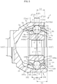
- FIG. 1a is a longitudinal sectional view for illustrating the fixed type constant velocity universal joint according to one embodiment of the present invention.
- FIG. 1b is a right-side view of FIG. 1a .
- FIG. 2a is a longitudinal sectional view for illustrating the outer joint member of FIG. 1a .
- FIG. 2b is a right-side view of FIG. 2a .
- FIG. 3a is a front view for illustrating an inner joint member of FIG. 1a .
- FIG. 3b is a right-side view of FIG. 3a .
- a fixed type constant velocity universal joint 1 is of a cross track groove type and mainly comprises an outer joint member 2, an inner joint member 3, toque transmission balls 4 (hereinafter simply referred to as "balls"), and a cage 5.
- a spherical inner peripheral surface 6 of the outer joint member 2 has eight track grooves 7.
- a spherical outer peripheral surface 8 of the inner joint member 3 has eight track grooves 9 opposed to the track grooves 7 of the outer joint member 2.
- the cage 5 configured to retain the balls 4 is arranged between the spherical inner peripheral surface 6 of the outer joint member 2 and the spherical outer peripheral surface 8 of the inner joint member 3.
- a spherical outer peripheral surface 12 of the cage 5 is fitted to the spherical inner peripheral surface 6 of the outer joint member 2 in a freely slidable manner, and a spherical inner peripheral surface 13 of the cage 5 is fitted to the spherical outer peripheral surface 8 of the inner joint member 3 in a freely slidable manner.
- a curvature center of the spherical inner peripheral surface 6 of the outer joint member 2 and the curvature center of the spherical outer peripheral surface 8 of the inner joint member 3 are each formed at a joint center O.
- the curvature centers of the spherical outer peripheral surface 12 and the spherical inner peripheral surface 13 of the cage 5 which are fitted to the spherical inner peripheral surface 6 of the outer joint member 2 and the spherical outer peripheral surface 8 of the inner joint member 3, respectively, are also located at the joint center O.
- a radially inner hole 10 of the inner joint member 3 has a female spline (the spline includes a serration, which similarly applies in the following description) 11, and a male spline 15 formed at an end portion of an intermediate shaft 14 (see FIG. 6a ) is fitted to the female spline 11, thereby coupling the intermediate shaft 14 to the inner joint member 3 so as to enable transmission of torque.
- the inner joint member 3 and the intermediate shaft 14 are positioned in an axial direction by a stopper ring 16.
- the eight track grooves 7 and 9 of the outer joint member 2 and the inner joint member 3 extend substantially in the axial direction.
- the track grooves 7 and 9 are formed with such inclination directions that track grooves 7A and 7B adjacent to each other in the circumferential direction are inclined in opposite directions and that the track grooves 9A and 9B adjacent to each other in the circumferential direction are inclined in opposite directions.
- the eight balls 4 are arranged at respective intersecting portions of paired track grooves 7A and 9A and paired track grooves 7B and 9B of the outer joint member 2 and the inner joint member 3.
- the axis N-N of the joint serves also as an axis No-No of the outer joint member and an axis Ni-Ni of the inner joint member.
- the fixed type constant velocity universal joint according to this embodiment is described as an example of a configuration described in Claims in which "the raceway center line (X) of the track groove of the outer joint member comprises an arc-shaped portion having a curvature center that has no offset with respect to the joint center (O) in the axial direction, and a portion different in shape from the arc-shaped portion, in which the portion different in shape from the arc-shaped portion is smoothly connected to the arc-shaped portion at a connection point (J), and in which the connection point (J) is located more on the opening side of the outer joint member than the joint center (O)".
- the raceway center line (X) of the track groove of the outer joint member comprises an arc-shaped portion having a curvature center that has no offset with respect to the joint center (O) in the axial direction, and a portion different in shape from the arc-shaped portion, in which the portion different in shape from the arc-shaped portion is smoothly connected to the arc-shaped portion at a connection point (J), and in
- the above-mentioned raceway center line X of the track groove of the outer joint member comprises the arc-shaped portion having the curvature center that has no offset with respect to the joint center O in the axial direction, and the portion different in shape from the arc-shaped portion.
- the track groove 7 of the outer joint member 2 has the raceway center line X.
- the track groove 7 is formed of a first track groove portion 7a and a second track groove portion 7b.
- the first track groove portion 7a has an arc-shaped raceway center line Xa having a curvature center at the joint center O.
- the second track groove portion 7b has a linear raceway center line Xb.
- the raceway center line Xb of the second track groove portion 7b is smoothly connected as a tangent to the raceway center line Xa of the first track groove portion 7a.
- the linear portion described above is the portion different in shape from the arc-shaped portion mentioned above.
- the raceway center line Xa of the first track groove portion 7a corresponds to "the arc-shaped portion having the curvature center that has no offset with respect to the joint center (O) in the axial direction", and the raceway center line X of the track groove of the outer joint member in Description and Claims comprises at least the above-mentioned arc-shaped portion.
- raceway center line corresponds to a locus formed by a center of the ball when the ball arranged in the track groove moves along the track groove.
- the track groove 9 of the inner joint member 3 has a raceway center line Y.
- the track groove 9 is formed of a first track groove portion 9a and a second track groove portion 9b.
- the first track groove portion 9a has an arc-shaped raceway center line Ya having a curvature center at the joint center O.
- the second track groove portion 9b has a linear raceway center line Yb.
- the raceway center line Yb of the second track groove portion 9b is smoothly connected as a tangent to the raceway center line Ya of the first track groove portion 9a.
- Respective curvature centers of the raceway center lines Xa and Ya of the first track groove portions 7a and 9a of the outer joint member 2 and the inner joint member 3 are arranged at the joint center O, that is, on the axis N-N of the joint. As a result, the depths of the track grooves can be uniformly set, and processing can easily be carried out.
- FIG. 2a and FIG. 2b a detailed description is made of the state in which the track grooves 7 of the outer joint member 2 are inclined in the circumferential direction with respect to the axis N-N of the joint.
- the track grooves 7 of the outer joint member 2 are denoted by reference symbols 7A and 7B based on the difference in the inclination directions.
- a plane M including the raceway center line X of the track groove 7A and the joint center O is inclined by the angle ⁇ with respect to the axis N-N of the joint.
- the plane M including the raceway center line X of the track groove 7B and the joint center O is inclined by the angle ⁇ with respect to the axis N-N of the joint in the direction opposite to the inclination direction of the track groove 7A.
- the entirety of the raceway center line X of the track groove 7A that is, both of the raceway center line Xa of the first track groove portion 7a and the raceway center line Xb of the second track groove portion 7b are formed on the plane M.
- the entire track groove of the outer joint member 2 is denoted by reference symbol 7.
- the first track groove portion of the track groove is denoted by reference symbol 7a
- the second track groove portion is denoted by reference symbol 7b.
- track grooves having different inclination directions are denoted by reference symbols 7A and 7B for distinction.
- Respective first track groove portions are denoted by reference symbols 7Aa and 7Ba
- respective second track groove portions are denoted by reference symbols 7Ab and 7Bb.
- the track grooves of the inner joint member 3 to be described later are denoted by reference symbols in a similar manner.
- FIG. 3a and FIG. 3b a detailed description is made of the state in which the track grooves 9 of the inner joint member 3 are inclined in the circumferential direction with respect to the axis N-N of the joint.
- the track grooves 9 of the inner joint member 3 are denoted by reference symbols 9A and 9B based on the difference in the inclination directions.
- a plane Q including the raceway center line Y of the track groove 9A and the joint center O is inclined by the angle ⁇ with respect to the axis N-N of the joint.
- the plane Q including the raceway center line Y of the track groove 9B and the joint center O is inclined by the angle ⁇ with respect to the axis N-N of the joint in the direction opposite to the inclination direction of the track groove 9A. It is preferred that the inclination angle ⁇ be set within the range of from 4° to 12° in consideration of the operability of the fixed type constant velocity universal joint 1 and a spherical surface width I on the side on which the track grooves of the inner joint member 3 are closest to each other.
- the entirety of the raceway center line Y of the track groove 9A that is, both of the raceway center line Ya of the first track groove portion 9a and the raceway center line Yb of the second track groove portion 9b are formed on the plane Q.
- the raceway center line Y of the track groove 9 of the inner joint member 3 is formed so as to be mirror-symmetric with the raceway center line X of the paired track groove 7 of the outer joint member 2 with the plane P including the joint center O and being orthogonal to the axis N-N of the joint in the state of the operating angle of 0° as a reference.
- FIG. 1a a detailed description is made of the track grooves of the outer joint member 2 and the inner joint member 3 as seen on the longitudinal cross section.
- FIG. 1a is a sectional view taken along the plane M of FIG. 2a including the raceway center line X of the track groove 7A of the outer joint member 2 and the joint center O.
- FIG. 1a is not a longitudinal sectional view taken along the plane including the axis N-N of the joint and is an illustration of the cross section inclined by the angle ⁇ .
- the track groove 7A of the outer joint member 2 is illustrated.
- the track groove 7B has the inclination direction opposite to that of the track groove 7A, and other configurations of the track groove 7B are the same as those of the track groove 7A. Therefore, description of the track groove 7B is omitted.
- the spherical inner peripheral surface 6 of the outer joint member 2 has the track grooves 7A extending substantially along the axial direction.
- the track groove 7A has the raceway center line X.
- the track groove 7A is formed of the first track groove portion 7Aa and the second track groove portion 7Ab.
- the first track groove portion 7Aa has the arc-shaped raceway center line Xa having a curvature center at the joint center O (no offset in the axial direction).
- the second track groove portion 7Ab has the linear raceway center line Xb.
- the linear raceway center line Xb of the second track groove portion 7Ab is smoothly connected as a tangent. That is, the end portion J serves as a connection point between the first track groove portion 7Aa and the second track groove portion 7Ab.
- the end portion J is located more on the opening side than the joint center O. Therefore, the linear raceway center line Xb of the second track groove portion 7Ab connected as a tangent at the end portion J of the raceway center line Xa of the first track groove portion 7Aa on the opening side is formed in such a manner as to approach the axis N-N of the joint as approaching the opening side.
- the length of the track that is effective can be increased, and the wedge angle can be prevented from being excessively large.
- a straight line connecting the end portion J and the joint center O to each other is denoted by reference symbol S.
- An axis N'-N' of the joint projected on the plane M including the raceway center line X of the track groove 7A and the joint center O is inclined by the angle ⁇ with respect to the axis N-N of the joint, and an angle formed between a perpendicular line K, which is perpendicular to the axis N'-N' at the joint center O, and the straight line S is denoted by reference symbol ⁇ '.
- the perpendicular line K described above is located on the plane P including the joint center O and being orthogonal to the axis N-N of the joint in the state of the operating angle of 0°.
- FIG. 1a is a sectional view taken along the plane Q of FIG. 3a including the raceway center line Y of the track groove 9A of the inner joint member 3 and the joint center O.
- FIG. 1a is not a longitudinal sectional view taken along the plane including the axis N-N of the joint and is an illustration of the cross section inclined by the angle ⁇ .
- the track groove 9A of the inner joint member 3 is illustrated.
- the track groove 9B has the inclination direction opposite to that of the track groove 9A, and other configurations of the track groove 9B are the same as those of the track groove 9A. Therefore, description of the track groove 9B is omitted.
- the spherical outer peripheral surface 8 of the inner joint member 3 has the track grooves 9A extending substantially along the axial direction.
- the track groove 9A has the raceway center line Y.
- the track groove 9A is formed of a first track groove portion 9Aa and a second track groove portion 9Ab.
- the first track groove portion 9Aa has the arc-shaped raceway center line Ya having a curvature center at the joint center O (no offset in the axial direction).
- the second track groove portion 9Ab has the linear raceway center line Yb.
- the raceway center line Yb of the second track groove portion 9Ab is smoothly connected as a tangent. That is, the end portion J' serves as a connection point between the first track groove portion 9Aa and the second track groove portion 9Ab.
- the end portion J' is located more on the back side than the joint center O. Therefore, the linear raceway center line Yb of the second track groove portion 9Ab connected as a tangent at the end portion J' of the raceway center line Ya of the first track groove portion 9Aa on the back side is formed in such a manner as to approach the axis N-N of the joint as approaching the back side. With this configuration, the length of the track that is effective can be increased, and the wedge angle can be prevented from being excessively large.
- a straight line connecting the end portion J' and the joint center O to each other is denoted by reference symbol S'.
- the axis N'-N' of the joint projected on the plane Q including the raceway center line Y of the track groove 9A and the joint center O is inclined by the angle ⁇ with respect to the axis N-N of the joint, and an angle formed between the perpendicular line K, which is perpendicular to the axis N'-N' at the joint center O, and the straight line S' is denoted by reference symbol ⁇ '.
- the perpendicular line K described above is located on the plane P including the joint center O and being orthogonal to the axis N-N of the joint in the state of the operating angle of 0°.
- a normal operating angle of a joint is an operating angle that is formed in a fixed type constant velocity universal joint for a front drive shaft when an automobile with one passenger is steered to go straight on a horizontal and flat road.
- the normal operating angle is selected and determined within the range of from 2° to 15° depending on design conditions for various types of automobiles.
- the end portion J of the raceway center line Xa of the first track groove portion 7Aa corresponds to a center position of the ball that moves most toward the opening side along the axial direction at the time of the normal operating angle.
- the end portion J' of the raceway center line Ya of the first track groove portion 9Aa corresponds to a center position of the ball that moves most toward the back side along the axial direction at the time of the normal operating angle.
- the balls 4 are located at the first track groove portions 7Aa and 9Aa and the first track groove portions 7Ba and 9Ba, which have the opposite inclination direction, of the outer joint member 2 and the inner joint member 3. Therefore, forces acting in opposite directions are applied by the balls 4 to the pockets 5a of the cage 5 adjacent to each other in the circumferential direction, thereby stabilizing the cage 5 at the position of the joint center O (see FIG. 1a ).
- the balls 4 arranged in the circumferential direction are temporarily and separately located at the first track groove portions 7Aa and 9Aa and the second track groove portions 7Ab and 9Ab.
- the contact forces are generated at the spherical-surface contact portions 12 and 6 between the cage 5 and the outer joint member 2 and at the spherical-surface contact portions 13 and 8 between the cage 5 and the inner joint member 3.
- a moment and the forces applied to the cage 5 by the balls 4 are balanced, and hence the cage 5 is stable near a bisecting plane.
- the fixed type constant velocity universal joint 1 is thus capable of suppressing the torque loss and generation of heat as a whole. Accordingly, a fixed type constant velocity universal joint which is small in torque loss and generation of heat and is highly efficient can be achieved.
- FIG. 4 is an enlarged transverse sectional view for illustrating one ball and track grooves taken along the line P-P of FIG. 1a .
- a transverse sectional shape of each of the track grooves 7 of the outer joint member 2 and the track grooves 9 of the inner joint member 3 is an elliptical shape or a gothic-arch shape. As illustrated in FIG.
- an angle (contact angle ⁇ ) formed between a straight line passing through a center Ob of the ball 4 and each of the contacts C1, C2, C3 and C4 and a straight line passing through the center Ob of the ball 4 and the joint center O (see FIG. 1a ) be set to be equal to or larger than 30°.
- the transverse sectional shape of each of the track grooves 7 and 9 may be an arc shape, and the track grooves 7 and 9 and the balls 4 may be brought into circular contact with each other.
- the overall configuration of the fixed type constant velocity universal joint 1 according to this embodiment is as described above.
- the fixed type constant velocity universal joint 1 according to this embodiment is set to have a maximum operating angle that significantly exceeds 50°.
- the characteristic configurations are as described below.
- the fixed type constant velocity universal joint of the cross track groove type has the operation mode in which, when the maximum operating angle is taken, the ball loses a contact.
- the moment and the forces applied to the cage 5 by the balls 4 act so as to be balanced, and hence the cage 5 is not significantly displaced from the bisecting plane.
- the characteristic configuration (2) described above is combined with the advantageous characteristic configuration (1) that is basically provided to the fixed type constant velocity universal joint of the cross track groove type and is capable of minimizing reduction in constant velocity characteristic and transmission efficiency, and minimizing changes of internal forces.
- the fixed type constant velocity universal joint which has the maximum operating angle set to be larger than the hitherto-adopted operating angle (50°) and has the operation mode in which the ball loses a contact, can be dramatically improved in constant velocity characteristic, transmission efficiency, changes of internal forces, strength, and durability.
- FIG. 5 An upper half of FIG. 5 with respect to a center line (axis of the joint) is a longitudinal sectional view for illustrating the fixed type constant velocity universal joint 1 according to this embodiment, and a lower half of FIG. 5 is a longitudinal sectional view for illustrating the fixed type constant velocity universal joint of the cross track groove type having the hitherto-adopted maximum operating angle and comprising eight balls.
- a fixed type constant velocity universal joint 101 of the cross track groove type illustrated in the lower half of FIG. 5 has the hitherto-adopted maximum operating angle, that is, has the maximum operating angle of 47°.
- the fixed type constant velocity universal joint 101 mainly comprises an outer joint member 102, an inner joint member 103, balls 104, and a cage 105.
- Track grooves 107 of the outer joint member 102 and track grooves 109 of the inner joint member 103 of the fixed type constant velocity universal joint 101 are the same as the track grooves 7 and 9 in this embodiment, and hence only outlines thereof are described.
- the track grooves 107 of the outer joint member 102 of the fixed type constant velocity universal joint 101 are each formed of a first track groove portion 107a and a second track groove portion 107b
- the track grooves 109 of the inner joint member 103 of the fixed type constant velocity universal joint 101 are each formed of a first track groove portion 109a and a second track groove portion 109b.
- the first track groove portions 107a and 109a respectively have arc-shaped raceway center lines xa and ya each having a curvature center at the joint center O (no offset in the axial direction)
- the second track groove portions 107b and 109b respectively have linear raceway center lines xb and yb.
- the raceway center line xa of the first track groove portion 107a and the raceway center line xb of the second track groove portion 107b of the outer joint member 102 are tangentially and smoothly connected to each other at a connection point A that is more on the opening side than the joint center O.
- the raceway center line ya of the first track groove portion 109a and the raceway center line yb of the second track groove portion 109b of the inner joint member 103 are tangentially and smoothly connected to each other at a connection point A' on a back side.
- the track grooves 107 of the outer joint member 102 and the track grooves 109 of the inner joint member 103 are inclined in the circumferential direction with respect to the axis N-N of the joint, and are formed with such inclination directions that the track grooves 107 adjacent to each other in the circumferential direction are inclined in opposite directions and that the track grooves 109 adjacent to each other in the circumferential direction are inclined in opposite directions.
- a straight line L or L' connecting the connection point A or A' and the joint center O to each other forms an angle ⁇ 1 with respect to the plane P including the joint center O and being orthogonal to the axis N-N of the joint .
- the angle ⁇ 1 is set to be larger than the angle ⁇ of the fixed type constant velocity universal joint 1 according to this embodiment.
- the fixed type constant velocity universal joint 101 has an operation mode in which the balls 104 are always kept in a contact state with respect to the track grooves 107 of the outer joint member 102 up to the maximum operating angle (47°).
- An inlet chamfer 120 formed at an opening-side end portion of the outer joint member 102 is set such that, at the maximum operating angle, an intermediate shaft does not interfere with the inlet chamfer 120 and that a contact state between the balls 104 and the track grooves 107 of the outer joint member 102 is kept. Accordingly, an axial dimension L2 from the joint center O to an opening-side end surface of the outer joint member 102 is set to be relatively long.
- the intermediate shaft interferes with the inlet chamfer 120.
- the inlet chamfer 120 is moved in the axial direction toward the joint center O, and an inclination angle is suitably increased.
- the maximum operating angle of the fixed type constant velocity universal joint 1 is set to be significantly larger than the hitherto-adopted maximum operating angle.
- an axial dimension L1 from the joint center O to an opening-side end surface of the outer joint member 2 is smaller than the axial dimension L2 from the joint center O to an opening-side end surface of the outer joint member 102 of the fixed type constant velocity universal joint 101 having the hitherto-adopted maximum operating angle, which is illustrated in the lower half of FIG. 5 .
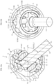
- FIG. 6a is a longitudinal sectional view for illustrating the fixed type constant velocity universal joint 1 when the fixed type constant velocity universal joint 1 takes the maximum operating angle.
- FIG. 6b is a right-side view of FIG. 6a .
- a length of each of the track grooves 7 on the opening side of the outer joint member 2 is reduced. Accordingly, in the operation mode of the fixed type constant velocity universal joint 1 according to this embodiment, as illustrated in FIG.
- FIG. 6a is an illustration of a state in which the axis Ni-Ni of the inner joint member 3 (intermediate shaft 14) is bent with respect to the axis No-No of the outer joint member 2 to the maximum operating angle ⁇ max (for example, 55°) on the drawing sheet of FIG. 6a .
- An axis Nc-Nc of the cage 5 is inclined at a bisecting angle ⁇ max/2.
- an illustration of the center Ob of the uppermost ball 4 is slightly displaced in the circumferential direction from the phase angle of 0° due to a relationship with the inclination angle ⁇ of the track groove 7 of the outer joint member 2.
- the phase angle of 0° refers to an angular position of the center Ob of the uppermost (top) ball 4 in the circumferential direction under a state in which the operating angle is 0° as illustrated in FIG. 1b .
- the phase angle is indicated as proceeding in a counterclockwise direction from the phase angle of 0° (the phase angle of 0° is indicated by " ⁇ 0" in FIG. 6b , and hereinafter also referred to as " ⁇ 0").
- the term "maximum operating angle ⁇ max" is used with the meaning of a maximum operating angle that is allowed when the fixed type constant velocity universal joint 1 is used.
- FIG. 6a is an illustration of a state in which the intermediate shaft 14 is in abutment against the inlet chamfer 20 at the time of the maximum operating angle.
- the inlet chamfer 20 is set so as to have such a shape and a dimension that a slight margin is given with respect to a radially outer surface of the intermediate shaft 14 when the maximum operating angle is taken.
- the inlet chamfer 20 functions as a stopper surface for a case in which the intermediate shaft 14 exceeds the maximum operating angle.
- the ball 4 which is located around the phase angle ⁇ 0 and moves toward the opening side of the track groove 7 of the outer joint member 2, comes off the opening-side end portion of the track groove 7 of the outer joint member 2 (inlet chamfer 20) and loses a contact with the track groove 7. Further, the ball 4 comes off the back-side end portion of the track groove 9 of the inner joint member 3 and loses a contact with the track groove 9. This state is described in detail with reference to FIG. 7 for illustrating the portion E of FIG. 6a in an enlarged manner.
- a surface position 4ao of the ball 4 when the ball 4 comes into contact with the track groove 7 and the inlet chamfer 20 formed at the opening-side end portion of the outer joint member 2, a surface position 4ai of the ball 4 when the ball 4 comes into contact with the track groove 9, and a surface position 4b of the ball 4 when the ball 4 comes into contact with the pocket 5a of the cage 5 are each indicated by a broken line.
- a contact locus obtained by connecting the contacts C2 (or C1, see FIG. 4 ), which are given between the track groove 7 of the outer joint member 2 and the ball 4, in the axial direction is denoted by CLo
- the contact locus CLo and the contact locus CLi are each indicated by a broken line.
- the contact loci CLo and CLi are formed at positions apart from the groove bottoms of the track grooves 7 and 9, respectively.
- the contact locus CLo ends at an edge portion of the inlet chamfer 20 on the opening side of the outer joint member 2.
- the edge portion of the inlet chamfer 20 is the opening-side end portion of the track groove 7 of the outer joint member 2.
- the surface position 4ao of the ball 4 is on a right side in FIG. 7 with respect to the end of the contact locus CLo, and the ball 4 and the track groove 7 are in a non-contact state.
- the ball 4 that loses a contact with the track groove 7 is one or two of the eight balls, and the one or two balls 4 are not involved in torque transmission.
- the contact locus CLi of the track groove 9 of the inner joint member 3 ends at the back-side end portion 3a.
- the surface position 4ai of the ball 4 is on a left side in FIG. 7 with respect to the end of the contact locus CLi, and the ball 4 and the track groove 9 are in a non-contact state.
- An interval between the surface position 4ao of the ball 4 and the end of the contact locus CLo on the track groove 7 of the outer joint member 2 is set to be larger than an interval between the surface position 4ai of the ball 4 and the end of the contact locus CLi on the track groove 9 of the inner joint member 3.
- a contact state between the surface position 4b of the ball 4 and the pocket 5a of the cage 5 is kept at a radial position before the spherical outer peripheral surface 12 of the cage 5.
- the pocket 5a and the ball 4 are fitted to each other with an extremely slight interference margin, and the ball 4 and the track groove 9 of the inner joint member 3 are in a non-contact state.
- no inevitable interference occurs between the track groove 9 and the ball 4.
- the ball 4 is reliably retained in the pocket 5a, and for example, generation of noise is prevented.
- a distance W between the edge portion of the inlet chamfer 20 of the track groove 7 and an edge portion of the pocket 5a of the cage 5 is set so as to satisfy a relationship of Db>W with a diameter Db of the ball 4, and hence the ball 4 is prevented from being dropped off.
- FIG. 8 is an illustration in which the range in which the ball 4 comes off the track groove 7 of the outer joint member 2 at the maximum operating angle is illustrated on FIG. 1b .
- the range in which the ball 4 comes off the track groove 7 of the outer joint member 2 is indicated by the arrows.
- the leader line of each arrow indicates the center Ob of the ball 4.
- the track grooves 7A and 7B of the outer joint member 2 each have the inclination angle ⁇ with respect to the axis N-N of the joint in the circumferential direction, and the track grooves 7A and 7B are formed with such inclination directions that the track grooves 7A and 7B adjacent to each other in the circumferential direction are inclined in opposite directions. Accordingly, as illustrated in FIG. 8 , a phase angle range M A in which the ball 4 comes off the track groove 7A is slightly different from a phase angle range M B in which the ball 4 comes off the track groove 7B.
- the ball 4 comes off the opening-side end portion of the track groove 7A of the outer joint member 2, and loses a contact with the track groove 7A to start a non-contact state with respect to the track groove 7A.
- one ball 4 is described as an example. However, in actuality, when the fixed type constant velocity universal joint 1 is rotated, the eight balls 4 sequentially pass through the phase angle range in which the balls 4 are brought into the non-contact state.
- the ball 4 located in the track groove 7B also has the same operation as that of the ball 4 located in the track groove 7A. However, the track groove 7B is formed so as to have the inclination direction opposite to the inclination direction of the track groove 7A.
- the ball 4 comes off the opening-side end portion of the track groove 7B of the outer joint member 2, and loses a contact with the track groove 7B to start a non-contact state with respect to the track groove 7B.
- the ball 4 returns to the opening-side end portion of the track groove 7B of the outer joint member 2 to start a contact state with respect to the track groove 7B.
- the range M A in which the ball 4 comes off the track groove 7A is slightly different from the range M B in which the ball 4 comes off the track groove 7B.
- FIG. 9 is a development view of an inner peripheral surface of the outer joint member, for illustrating a difference given by inclination directions of the track grooves between ranges in which the torque transmission balls lose contacts with the track grooves of the outer joint member of FIG. 8 .
- a right side of a center line extending in the up-and-down direction of the drawing sheet of FIG. 9 is an illustration of a state in which the ball 4 comes off the track groove 7A, and a left side thereof is an illustration of a state in which the ball 4 comes off the track groove 7B.
- the outline arrow of FIG. 9 indicates a direction of applying torque from the inner joint member 3 to the outer joint member 2.
- the outline arrow of FIG. 11 or FIG. 14 to be described later similarly indicates the torque applying direction.
- the track grooves 7 are inclined with respect to the axis.
- the ball 4 is brought into contact with the track groove 7A at a position displaced toward the back side with respect to the center Ob of the ball 4, and the ball 4 is brought into contact with the track groove 7B at a position displaced toward the opening side with respect to the center Ob of the ball 4.
- the surface position 4ao of the ball 4 arrives at the end of the contact locus CLo of the track groove 7A (edge portion of the inlet chamfer 20) so that the ball 4 is at the phase angle ⁇ 2 A at which the ball 4 loses a contact.
- the surface position 4ao of the ball 4 arrives at the end of the contact locus CLo of the track groove 7B (edge portion of the inlet chamfer 20) so that the ball 4 is at the phase angle ⁇ 2 B at which the ball 4 loses a contact. Accordingly, a difference is made between the phase angles ⁇ 2 A and ⁇ 2 B .
- phase angle ⁇ 1 at which the ball 4 returns to the track groove 7 to start a contact state, and hence a development view is omitted.
- the surface position 4ao of the ball 4 returns to the end of the contact locus CLo of the track groove 7A (edge portion of the inlet chamfer 20) to start a contact state.
- the phase angle ⁇ 1 B at the phase angle ⁇ 1 B (see FIG. 8 ), the surface position 4ao of the ball 4 returns to the end of the contact locus CLo of the track groove 7B (edge portion of the inlet chamfer 20) to start a contact state.
- the range M A in which the ball 4 loses a contact with the track groove 7A is smaller than the range M B in which the ball 4 loses a contact with the track groove 7B.
- the range M A in which the ball 4 loses a contact with the track groove 7A is larger than the range M B in which the ball 4 loses a contact with the track groove 7B.
- the ball 4 located around the phase angle ⁇ 0 which moves toward the opening side of the track groove 7 of the outer joint member 2, comes off the opening-side end portion (inlet chamfer 20) of the track groove 7 of the outer joint member 2 and loses a contact with the track groove 7, and the ball 4 comes off the back-side end portion of the track groove 9 of the inner joint member 3 and loses a contact with the track groove 9.
- the ball 4 comes off the back-side end portion of the track groove 9 of the inner joint member 3 and loses a contact with the track groove 9.
- the characteristic configuration (1) of the fixed type constant velocity universal joint according to this embodiment is summarized below.
- the fixed type constant velocity universal joint of the cross track groove type as a base
- the fixed type constant velocity universal joint according to this embodiment has the operation mode in which the ball loses a contact when the maximum operating angle is taken.
- the moment and the forces applied to the cage 5 by the balls 4 act so as to be balanced, and hence the cage 5 is not significantly displaced from the bisecting plane. Accordingly, reduction in constant velocity characteristic and transmission efficiency, and changes of internal forces can be minimized.
- the characteristic configuration (2) of the fixed type constant velocity universal joint that is, a configuration in which, when the large operating angle is taken, the operating angle ⁇ 2 at which the ball 4 loses a contact with the track groove 9 of the inner joint member 3 is set to be larger than the operating angle ⁇ 1 at which the ball 4 loses a contact with the track groove 7 of the outer joint member 2.
- FIG. 10a is a longitudinal sectional view for illustrating a state in which the torque transmission ball loses a contact with the track groove of the outer joint member when the fixed type constant velocity universal joint of FIG. 1a and FIG. 1b takes a large operating angle.
- FIG. 10b is a right-side view of FIG. 10a .
- FIG. 11 is a development view of the inner peripheral surface of the outer joint member, for illustrating a state in which the torque transmission ball loses a contact with the track groove of the outer joint member of FIG. 10b .
- FIG. 12 is an enlarged longitudinal sectional view for illustrating the portion F of FIG. 10a .
- the ball 4 moves toward the opening side of the track groove 7 of the outer joint member 2, and arrives at the edge portion of the inlet chamfer 20 of the track groove 7 so that the ball 4 loses a contact with the track groove 7 of the outer joint member 2.
- the operating angle at which the ball loses a contact corresponds to the operating angle ⁇ 1 at which the ball 4 loses a contact with the track groove 7 of the outer joint member 2.
- FIG. 11 is an illustration of a state in which, among the balls 4 located in the track grooves 7A, the center Ob of the ball 4, which has moved to an end position in the axial direction toward the opening side of the outer joint member 2, is located at the phase angle ⁇ 0.
- the surface position 4ao of the ball 4 located in the track groove 7A arrives at an opening-side end of the contact locus CLo, that is, the edge portion of the inlet chamfer 20 so that the fixed type constant velocity universal joint 1 takes the operating angle ⁇ 1 A at which the ball 4 loses a contact with the track groove 7A.
- illustration is omitted, the same holds true for a case of the track groove 7B.
- the operating angle ⁇ 1 is defined as an operating angle at which the ball 4 loses a contact when the center Ob of the ball 4 is located at the phase angle ⁇ 0.
- the operating angles ⁇ 1 A and ⁇ 1 B are collectively referred to as "the operating angle ⁇ 1".
- a phrase of "an operating angle ( ⁇ 1) at which the torque transmission ball loses a contact with the track groove of the outer joint member" is used with the meaning described above.
- the track grooves 7B and the balls 4 that are located at the phase angle apart from the phase angle ⁇ 0 are in a contact state at the contacts C1, and bear load.
- the surface position 4ai of the ball 4 is within an axial range of the contact locus CLi of the track groove 9A of the inner joint member 3, and the track groove 9A and the ball 4 are in a contact state at the contact C3. Accordingly, at the point in time when the ball 4 loses a contact with the track groove 7A of the outer joint member 2 and when the ball 4 located with the same positional relationship returns to the track groove 7 of the outer joint member 2, the ball 4 can bear load on the track groove 9 of the inner joint member 3.
- FIG. 13a is a longitudinal sectional view for illustrating a state in which the torque transmission ball loses a contact with the track groove of the inner joint member when the fixed type constant velocity universal joint of FIG. 1a and FIG. 1b takes a large operating angle.
- FIG. 13b is a right-side view of FIG. 13a .
- FIG. 14 is a development view of the inner peripheral surface of the outer joint member, for illustrating a positional relationship between the track groove of the outer joint member and the torque transmission ball when the fixed type constant velocity universal joint takes the operating angle in FIG. 13b .
- FIG. 15 is an enlarged longitudinal sectional view for illustrating the portion H of FIG. 13a .
- FIG. 15 A positional relationship between the track grooves 9 of the inner joint member 3 and the balls 4 at the time of the operating angle ⁇ 2 is described in detail with reference to FIG. 15 .
- a load range between the ball 4 and the track groove 7A or the track groove 7B is the contact locus CLi on the upper side of the drawing sheet of FIG. 14.
- 15 is an illustration of a state in which, when the surface position 4ai of the ball 4, which has lost a contact with the track groove 7A of the outer joint member 2, arrives at the end of the contact locus CLi and the ball 4 loses a contact with the track groove 9A of the inner joint member 3, the center Ob of the ball 4 at this time is located at the phase angle ⁇ 0.
- the operating angle under this state corresponds to an operating angle ⁇ 2 A at which the ball 4 loses a contact with the track groove 9A of the inner joint member 3.
- the operating angle ⁇ 2 at which the ball 4 loses a contact with the track groove 9 of the inner joint member 3 is also defined as the operating angle at which the ball 4 loses a contact when the center Ob of the ball 4 is located at the phase angle ⁇ 0. Further, the operating angles ⁇ 2 A and ⁇ 2 B are collectively referred to as "operating angle ⁇ 2". In Description and Claims, a phrase of "an operating angle ( ⁇ 2) at which the torque transmission ball loses a contact with the track groove of the inner joint member" is used with the meaning described above.
- the operating angle ⁇ 2 at which the torque transmission ball 4 loses a contact with the track groove 9 of the inner joint member 3 is set to be larger than the operating angle ⁇ 1 at which the torque transmission ball 4 loses a contact with the track groove 7 of the outer joint member 2.
- a minimum value of a difference between the operating angle ⁇ 2 at which the torque transmission ball 4 loses a contact with the track groove 9 of the inner joint member 3 and the operating angle ⁇ 1 at which the torque transmission ball 4 loses a contact with the track groove 7 of the outer joint member 2 is set to 3°.
- a maximum value of the difference is set to an angle at which the ball 4 can keep a contact with a radially outer side of the cage.
- the characteristic configuration (2) of this embodiment described above is summarized below.
- the load of the ball 4 can be borne on the track groove 9 of the inner joint member 3. Accordingly, without increasing the internal forces, damage to the opening-side end portion of the outer joint member 2 can be prevented, thereby being capable of improving strength and durability.
- the fixed type constant velocity universal joint 1 has the operation mode in which, when the maximum operating angle is taken, the ball loses a contact in the fixed type constant velocity universal joint of the cross track groove type.
- the characteristic configuration (2) is combined with the advantageous characteristic configuration (1) that is basically provided to the fixed type constant velocity universal joint of the cross track groove type and is capable of minimizing reduction in constant velocity characteristic and transmission efficiency, and minimizing changes of internal forces.
- the fixed type constant velocity universal joint 1 in which the track grooves 7 of the outer joint member 2, which are inclined in the circumferential direction, each comprise the first track groove portion 7a having the arc-shaped raceway center line Xa having the curvature center at the joint center O, and the second track groove portion 7b having the linear raceway center line Xb, and in which the track grooves 9 of the inner joint member 3, which are inclined in the circumferential direction, each comprise the first track groove portion 9a having the arc-shaped raceway center line Ya having the curvature center at the joint center O, and the second track groove portion 9b having the linear raceway center line Yb.
- the present invention is not limited thereto.
- the present invention is also applicable to a fixed type constant velocity universal joint in which the track grooves 7 of the outer joint member 2 inclined in the circumferential direction each have, in an entire axial region thereof, the arc-shaped raceway center line X having the curvature center at the joint center O, and in which the track grooves 9 of the inner joint member 3 inclined in the circumferential direction each have, in an entire axial region thereof, the arc-shaped raceway center line Y having the curvature center at the joint center O.
Landscapes
- Engineering & Computer Science (AREA)
- General Engineering & Computer Science (AREA)
- Mechanical Engineering (AREA)
- Rolling Contact Bearings (AREA)
- Rear-View Mirror Devices That Are Mounted On The Exterior Of The Vehicle (AREA)
- Pivots And Pivotal Connections (AREA)
- Bearings For Parts Moving Linearly (AREA)
Applications Claiming Priority (2)
| Application Number | Priority Date | Filing Date | Title |
|---|---|---|---|
| JP2019072801A JP7458712B2 (ja) | 2019-04-05 | 2019-04-05 | 固定式等速自在継手 |
| PCT/JP2020/011404 WO2020203215A1 (ja) | 2019-04-05 | 2020-03-16 | 固定式等速自在継手 |
Publications (3)
| Publication Number | Publication Date |
|---|---|
| EP3951202A1 true EP3951202A1 (de) | 2022-02-09 |
| EP3951202A4 EP3951202A4 (de) | 2023-01-11 |
| EP3951202B1 EP3951202B1 (de) | 2024-05-15 |
Family
ID=72668606
Family Applications (1)
| Application Number | Title | Priority Date | Filing Date |
|---|---|---|---|
| EP20785388.8A Active EP3951202B1 (de) | 2019-04-05 | 2020-03-16 | Universelles gleichlauffestgelenk |
Country Status (5)
| Country | Link |
|---|---|
| US (1) | US12055188B2 (de) |
| EP (1) | EP3951202B1 (de) |
| JP (1) | JP7458712B2 (de) |
| CN (1) | CN113661337B (de) |
| WO (1) | WO2020203215A1 (de) |
Family Cites Families (20)
| Publication number | Priority date | Publication date | Assignee | Title |
|---|---|---|---|---|
| JPS4885236U (de) | 1972-01-14 | 1973-10-16 | ||
| EP1326027B1 (de) * | 1997-07-16 | 2006-02-01 | Nsk Ltd | Homokinetisches Gelenk für Räder |
| EP1881218A4 (de) * | 2005-05-12 | 2009-03-04 | Ntn Toyo Bearing Co Ltd | Universelles gleichlauffestgelenk |
| DE102005023035A1 (de) | 2005-05-13 | 2006-11-23 | Gkn Driveline Deutschland Gmbh | Gelenk mit vergrößertem Öffnungswinkel |
| JP2006336773A (ja) | 2005-06-02 | 2006-12-14 | Ntn Corp | 固定型等速自在継手 |
| JP2007064404A (ja) * | 2005-08-31 | 2007-03-15 | Ntn Corp | 固定式等速自在継手 |
| JP5073190B2 (ja) * | 2005-09-22 | 2012-11-14 | Ntn株式会社 | 摺動式等速自在継手 |
| JP4885236B2 (ja) | 2005-12-29 | 2012-02-29 | ジーケイエヌ ドライヴライン インターナショナル ゲゼルシャフト ミット ベシュレンクテル ハフツング | 大きな屈曲角の固定式等速自在継手 |
| JP2008075820A (ja) * | 2006-09-22 | 2008-04-03 | Ntn Corp | 固定型等速自在継手 |
| CN101542149B (zh) * | 2006-10-13 | 2013-10-16 | Gkn动力传动系统国际有限责任公司 | 呈相对滚道接头形式的等速球形接头 |
| JP2009228811A (ja) * | 2008-03-24 | 2009-10-08 | Ntn Corp | 等速自在継手 |
| JP5131064B2 (ja) * | 2008-07-14 | 2013-01-30 | 株式会社ジェイテクト | ボール型等速ジョイント |
| JP2012017844A (ja) | 2010-02-16 | 2012-01-26 | Ntn Corp | 固定式等速自在継手及び等速自在継手用ブーツ |
| JP5885997B2 (ja) * | 2011-05-30 | 2016-03-16 | Ntn株式会社 | 固定式等速自在継手 |
| JP5840463B2 (ja) * | 2011-11-10 | 2016-01-06 | Ntn株式会社 | 固定式等速自在継手 |
| KR101336506B1 (ko) * | 2011-11-16 | 2013-12-03 | 현대위아 주식회사 | 차량용 볼타입 등속조인트 |
| JP2017020543A (ja) * | 2015-07-08 | 2017-01-26 | Ntn株式会社 | 固定式等速自在継手 |
| JP6821295B2 (ja) * | 2015-09-24 | 2021-01-27 | Ntn株式会社 | 固定式等速自在継手 |
| JP6832629B2 (ja) * | 2016-03-25 | 2021-02-24 | Ntn株式会社 | 固定式等速自在継手 |
| JP7139269B2 (ja) * | 2018-04-03 | 2022-09-20 | Ntn株式会社 | 固定式等速自在継手 |
-
2019
- 2019-04-05 JP JP2019072801A patent/JP7458712B2/ja active Active
-
2020
- 2020-03-16 US US17/599,770 patent/US12055188B2/en active Active
- 2020-03-16 CN CN202080026424.9A patent/CN113661337B/zh active Active
- 2020-03-16 EP EP20785388.8A patent/EP3951202B1/de active Active
- 2020-03-16 WO PCT/JP2020/011404 patent/WO2020203215A1/ja not_active Ceased
Also Published As
| Publication number | Publication date |
|---|---|
| EP3951202B1 (de) | 2024-05-15 |
| JP2020169716A (ja) | 2020-10-15 |
| WO2020203215A1 (ja) | 2020-10-08 |
| CN113661337B (zh) | 2024-10-29 |
| WO2020203215A8 (ja) | 2021-09-16 |
| CN113661337A (zh) | 2021-11-16 |
| EP3951202A4 (de) | 2023-01-11 |
| US12055188B2 (en) | 2024-08-06 |
| JP7458712B2 (ja) | 2024-04-01 |
| US20220056960A1 (en) | 2022-02-24 |
Similar Documents
| Publication | Publication Date | Title |
|---|---|---|
| EP2719911B1 (de) | Universelles gleichlauffestgelenk | |
| EP2778454B1 (de) | Universales festgleichlaufgelenk | |
| EP2716926B1 (de) | Universelles gleichlauffestgelenk | |
| EP2905491B1 (de) | Festes universelles gleichlaufgelenk | |
| US20140329608A1 (en) | Fixed type constant velocity universal joint | |
| EP2908020B1 (de) | Festes gleichlauf-kardangelenk | |
| EP3951201B1 (de) | Universelles gleichlauffestgelenk | |
| EP2924306B1 (de) | Gleichlaufgelenk stationäre ausführung | |
| EP3067582B1 (de) | Stationäres gleichlaufgelenk | |
| US8342971B2 (en) | Fixed type constant velocity universal joint | |
| EP3951202B1 (de) | Universelles gleichlauffestgelenk | |
| JP2008151182A (ja) | 等速自在継手 | |
| US11927226B2 (en) | Fixed type constant velocity universal joint | |
| EP4394200A1 (de) | Tauchendes gleichlaufgelenk | |
| JP5241078B2 (ja) | 固定式等速自在継手 | |
| JP7370159B2 (ja) | 固定式等速自在継手 | |
| EP3015729B1 (de) | Festes universelles gleichlaufgelenk | |
| JP2008261390A (ja) | 固定式等速自在継手 | |
| WO2019194046A1 (ja) | 固定式等速自在継手 | |
| JP2008267407A (ja) | 固定式等速自在継手 |
Legal Events
| Date | Code | Title | Description |
|---|---|---|---|
| STAA | Information on the status of an ep patent application or granted ep patent |
Free format text: STATUS: THE INTERNATIONAL PUBLICATION HAS BEEN MADE |
|
| PUAI | Public reference made under article 153(3) epc to a published international application that has entered the european phase |
Free format text: ORIGINAL CODE: 0009012 |
|
| STAA | Information on the status of an ep patent application or granted ep patent |
Free format text: STATUS: REQUEST FOR EXAMINATION WAS MADE |
|
| 17P | Request for examination filed |
Effective date: 20211021 |
|
| AK | Designated contracting states |
Kind code of ref document: A1 Designated state(s): AL AT BE BG CH CY CZ DE DK EE ES FI FR GB GR HR HU IE IS IT LI LT LU LV MC MK MT NL NO PL PT RO RS SE SI SK SM TR |
|
| DAV | Request for validation of the european patent (deleted) | ||
| DAX | Request for extension of the european patent (deleted) | ||
| A4 | Supplementary search report drawn up and despatched |
Effective date: 20221209 |
|
| RIC1 | Information provided on ipc code assigned before grant |
Ipc: F16D 3/223 20110101ALI20221205BHEP Ipc: F16D 3/2245 20110101AFI20221205BHEP |
|
| GRAP | Despatch of communication of intention to grant a patent |
Free format text: ORIGINAL CODE: EPIDOSNIGR1 |
|
| STAA | Information on the status of an ep patent application or granted ep patent |
Free format text: STATUS: GRANT OF PATENT IS INTENDED |
|
| INTG | Intention to grant announced |
Effective date: 20240116 |
|
| GRAS | Grant fee paid |
Free format text: ORIGINAL CODE: EPIDOSNIGR3 |
|
| GRAA | (expected) grant |
Free format text: ORIGINAL CODE: 0009210 |
|
| STAA | Information on the status of an ep patent application or granted ep patent |
Free format text: STATUS: THE PATENT HAS BEEN GRANTED |
|
| AK | Designated contracting states |
Kind code of ref document: B1 Designated state(s): AL AT BE BG CH CY CZ DE DK EE ES FI FR GB GR HR HU IE IS IT LI LT LU LV MC MK MT NL NO PL PT RO RS SE SI SK SM TR |
|
| REG | Reference to a national code |
Ref country code: CH Ref legal event code: EP |
|
| REG | Reference to a national code |
Ref country code: IE Ref legal event code: FG4D |
|
| REG | Reference to a national code |
Ref country code: DE Ref legal event code: R096 Ref document number: 602020031011 Country of ref document: DE |
|
| REG | Reference to a national code |
Ref country code: LT Ref legal event code: MG9D |
|
| REG | Reference to a national code |
Ref country code: NL Ref legal event code: MP Effective date: 20240515 |
|
| PG25 | Lapsed in a contracting state [announced via postgrant information from national office to epo] |
Ref country code: IS Free format text: LAPSE BECAUSE OF FAILURE TO SUBMIT A TRANSLATION OF THE DESCRIPTION OR TO PAY THE FEE WITHIN THE PRESCRIBED TIME-LIMIT Effective date: 20240915 |
|
| PG25 | Lapsed in a contracting state [announced via postgrant information from national office to epo] |
Ref country code: BG Free format text: LAPSE BECAUSE OF FAILURE TO SUBMIT A TRANSLATION OF THE DESCRIPTION OR TO PAY THE FEE WITHIN THE PRESCRIBED TIME-LIMIT Effective date: 20240515 |
|
| PG25 | Lapsed in a contracting state [announced via postgrant information from national office to epo] |
Ref country code: HR Free format text: LAPSE BECAUSE OF FAILURE TO SUBMIT A TRANSLATION OF THE DESCRIPTION OR TO PAY THE FEE WITHIN THE PRESCRIBED TIME-LIMIT Effective date: 20240515 Ref country code: FI Free format text: LAPSE BECAUSE OF FAILURE TO SUBMIT A TRANSLATION OF THE DESCRIPTION OR TO PAY THE FEE WITHIN THE PRESCRIBED TIME-LIMIT Effective date: 20240515 |
|
| PG25 | Lapsed in a contracting state [announced via postgrant information from national office to epo] |
Ref country code: GR Free format text: LAPSE BECAUSE OF FAILURE TO SUBMIT A TRANSLATION OF THE DESCRIPTION OR TO PAY THE FEE WITHIN THE PRESCRIBED TIME-LIMIT Effective date: 20240816 |
|
| PG25 | Lapsed in a contracting state [announced via postgrant information from national office to epo] |
Ref country code: PT Free format text: LAPSE BECAUSE OF FAILURE TO SUBMIT A TRANSLATION OF THE DESCRIPTION OR TO PAY THE FEE WITHIN THE PRESCRIBED TIME-LIMIT Effective date: 20240916 |
|
| REG | Reference to a national code |
Ref country code: AT Ref legal event code: MK05 Ref document number: 1687137 Country of ref document: AT Kind code of ref document: T Effective date: 20240515 |
|
| PG25 | Lapsed in a contracting state [announced via postgrant information from national office to epo] |
Ref country code: NL Free format text: LAPSE BECAUSE OF FAILURE TO SUBMIT A TRANSLATION OF THE DESCRIPTION OR TO PAY THE FEE WITHIN THE PRESCRIBED TIME-LIMIT Effective date: 20240515 |
|
| PG25 | Lapsed in a contracting state [announced via postgrant information from national office to epo] |
Ref country code: ES Free format text: LAPSE BECAUSE OF FAILURE TO SUBMIT A TRANSLATION OF THE DESCRIPTION OR TO PAY THE FEE WITHIN THE PRESCRIBED TIME-LIMIT Effective date: 20240515 |
|
| PG25 | Lapsed in a contracting state [announced via postgrant information from national office to epo] |
Ref country code: AT Free format text: LAPSE BECAUSE OF FAILURE TO SUBMIT A TRANSLATION OF THE DESCRIPTION OR TO PAY THE FEE WITHIN THE PRESCRIBED TIME-LIMIT Effective date: 20240515 |
|
| PG25 | Lapsed in a contracting state [announced via postgrant information from national office to epo] |
Ref country code: PL Free format text: LAPSE BECAUSE OF FAILURE TO SUBMIT A TRANSLATION OF THE DESCRIPTION OR TO PAY THE FEE WITHIN THE PRESCRIBED TIME-LIMIT Effective date: 20240515 |
|
| PG25 | Lapsed in a contracting state [announced via postgrant information from national office to epo] |
Ref country code: LV Free format text: LAPSE BECAUSE OF FAILURE TO SUBMIT A TRANSLATION OF THE DESCRIPTION OR TO PAY THE FEE WITHIN THE PRESCRIBED TIME-LIMIT Effective date: 20240515 |
|
| PG25 | Lapsed in a contracting state [announced via postgrant information from national office to epo] |
Ref country code: PT Free format text: LAPSE BECAUSE OF FAILURE TO SUBMIT A TRANSLATION OF THE DESCRIPTION OR TO PAY THE FEE WITHIN THE PRESCRIBED TIME-LIMIT Effective date: 20240916 Ref country code: PL Free format text: LAPSE BECAUSE OF FAILURE TO SUBMIT A TRANSLATION OF THE DESCRIPTION OR TO PAY THE FEE WITHIN THE PRESCRIBED TIME-LIMIT Effective date: 20240515 Ref country code: NO Free format text: LAPSE BECAUSE OF FAILURE TO SUBMIT A TRANSLATION OF THE DESCRIPTION OR TO PAY THE FEE WITHIN THE PRESCRIBED TIME-LIMIT Effective date: 20240815 Ref country code: NL Free format text: LAPSE BECAUSE OF FAILURE TO SUBMIT A TRANSLATION OF THE DESCRIPTION OR TO PAY THE FEE WITHIN THE PRESCRIBED TIME-LIMIT Effective date: 20240515 Ref country code: LV Free format text: LAPSE BECAUSE OF FAILURE TO SUBMIT A TRANSLATION OF THE DESCRIPTION OR TO PAY THE FEE WITHIN THE PRESCRIBED TIME-LIMIT Effective date: 20240515 Ref country code: IS Free format text: LAPSE BECAUSE OF FAILURE TO SUBMIT A TRANSLATION OF THE DESCRIPTION OR TO PAY THE FEE WITHIN THE PRESCRIBED TIME-LIMIT Effective date: 20240915 Ref country code: HR Free format text: LAPSE BECAUSE OF FAILURE TO SUBMIT A TRANSLATION OF THE DESCRIPTION OR TO PAY THE FEE WITHIN THE PRESCRIBED TIME-LIMIT Effective date: 20240515 Ref country code: GR Free format text: LAPSE BECAUSE OF FAILURE TO SUBMIT A TRANSLATION OF THE DESCRIPTION OR TO PAY THE FEE WITHIN THE PRESCRIBED TIME-LIMIT Effective date: 20240816 Ref country code: FI Free format text: LAPSE BECAUSE OF FAILURE TO SUBMIT A TRANSLATION OF THE DESCRIPTION OR TO PAY THE FEE WITHIN THE PRESCRIBED TIME-LIMIT Effective date: 20240515 Ref country code: ES Free format text: LAPSE BECAUSE OF FAILURE TO SUBMIT A TRANSLATION OF THE DESCRIPTION OR TO PAY THE FEE WITHIN THE PRESCRIBED TIME-LIMIT Effective date: 20240515 Ref country code: BG Free format text: LAPSE BECAUSE OF FAILURE TO SUBMIT A TRANSLATION OF THE DESCRIPTION OR TO PAY THE FEE WITHIN THE PRESCRIBED TIME-LIMIT Effective date: 20240515 Ref country code: AT Free format text: LAPSE BECAUSE OF FAILURE TO SUBMIT A TRANSLATION OF THE DESCRIPTION OR TO PAY THE FEE WITHIN THE PRESCRIBED TIME-LIMIT Effective date: 20240515 Ref country code: RS Free format text: LAPSE BECAUSE OF FAILURE TO SUBMIT A TRANSLATION OF THE DESCRIPTION OR TO PAY THE FEE WITHIN THE PRESCRIBED TIME-LIMIT Effective date: 20240815 |
|
| PG25 | Lapsed in a contracting state [announced via postgrant information from national office to epo] |
Ref country code: DK Free format text: LAPSE BECAUSE OF FAILURE TO SUBMIT A TRANSLATION OF THE DESCRIPTION OR TO PAY THE FEE WITHIN THE PRESCRIBED TIME-LIMIT Effective date: 20240515 |
|
| PG25 | Lapsed in a contracting state [announced via postgrant information from national office to epo] |
Ref country code: EE Free format text: LAPSE BECAUSE OF FAILURE TO SUBMIT A TRANSLATION OF THE DESCRIPTION OR TO PAY THE FEE WITHIN THE PRESCRIBED TIME-LIMIT Effective date: 20240515 |
|
| PG25 | Lapsed in a contracting state [announced via postgrant information from national office to epo] |
Ref country code: CZ Free format text: LAPSE BECAUSE OF FAILURE TO SUBMIT A TRANSLATION OF THE DESCRIPTION OR TO PAY THE FEE WITHIN THE PRESCRIBED TIME-LIMIT Effective date: 20240515 |
|
| PG25 | Lapsed in a contracting state [announced via postgrant information from national office to epo] |
Ref country code: SK Free format text: LAPSE BECAUSE OF FAILURE TO SUBMIT A TRANSLATION OF THE DESCRIPTION OR TO PAY THE FEE WITHIN THE PRESCRIBED TIME-LIMIT Effective date: 20240515 Ref country code: RO Free format text: LAPSE BECAUSE OF FAILURE TO SUBMIT A TRANSLATION OF THE DESCRIPTION OR TO PAY THE FEE WITHIN THE PRESCRIBED TIME-LIMIT Effective date: 20240515 |
|
| PG25 | Lapsed in a contracting state [announced via postgrant information from national office to epo] |
Ref country code: SM Free format text: LAPSE BECAUSE OF FAILURE TO SUBMIT A TRANSLATION OF THE DESCRIPTION OR TO PAY THE FEE WITHIN THE PRESCRIBED TIME-LIMIT Effective date: 20240515 |
|
| PG25 | Lapsed in a contracting state [announced via postgrant information from national office to epo] |
Ref country code: SM Free format text: LAPSE BECAUSE OF FAILURE TO SUBMIT A TRANSLATION OF THE DESCRIPTION OR TO PAY THE FEE WITHIN THE PRESCRIBED TIME-LIMIT Effective date: 20240515 Ref country code: SK Free format text: LAPSE BECAUSE OF FAILURE TO SUBMIT A TRANSLATION OF THE DESCRIPTION OR TO PAY THE FEE WITHIN THE PRESCRIBED TIME-LIMIT Effective date: 20240515 Ref country code: RO Free format text: LAPSE BECAUSE OF FAILURE TO SUBMIT A TRANSLATION OF THE DESCRIPTION OR TO PAY THE FEE WITHIN THE PRESCRIBED TIME-LIMIT Effective date: 20240515 Ref country code: EE Free format text: LAPSE BECAUSE OF FAILURE TO SUBMIT A TRANSLATION OF THE DESCRIPTION OR TO PAY THE FEE WITHIN THE PRESCRIBED TIME-LIMIT Effective date: 20240515 Ref country code: DK Free format text: LAPSE BECAUSE OF FAILURE TO SUBMIT A TRANSLATION OF THE DESCRIPTION OR TO PAY THE FEE WITHIN THE PRESCRIBED TIME-LIMIT Effective date: 20240515 Ref country code: CZ Free format text: LAPSE BECAUSE OF FAILURE TO SUBMIT A TRANSLATION OF THE DESCRIPTION OR TO PAY THE FEE WITHIN THE PRESCRIBED TIME-LIMIT Effective date: 20240515 |
|
| PG25 | Lapsed in a contracting state [announced via postgrant information from national office to epo] |
Ref country code: IT Free format text: LAPSE BECAUSE OF FAILURE TO SUBMIT A TRANSLATION OF THE DESCRIPTION OR TO PAY THE FEE WITHIN THE PRESCRIBED TIME-LIMIT Effective date: 20240515 |
|
| REG | Reference to a national code |
Ref country code: DE Ref legal event code: R097 Ref document number: 602020031011 Country of ref document: DE |
|
| PLBE | No opposition filed within time limit |
Free format text: ORIGINAL CODE: 0009261 |
|
| STAA | Information on the status of an ep patent application or granted ep patent |
Free format text: STATUS: NO OPPOSITION FILED WITHIN TIME LIMIT |
|
| 26N | No opposition filed |
Effective date: 20250218 |
|
| PG25 | Lapsed in a contracting state [announced via postgrant information from national office to epo] |
Ref country code: SI Free format text: LAPSE BECAUSE OF FAILURE TO SUBMIT A TRANSLATION OF THE DESCRIPTION OR TO PAY THE FEE WITHIN THE PRESCRIBED TIME-LIMIT Effective date: 20240515 |
|
| PG25 | Lapsed in a contracting state [announced via postgrant information from national office to epo] |
Ref country code: SE Free format text: LAPSE BECAUSE OF FAILURE TO SUBMIT A TRANSLATION OF THE DESCRIPTION OR TO PAY THE FEE WITHIN THE PRESCRIBED TIME-LIMIT Effective date: 20240515 |
|
| PG25 | Lapsed in a contracting state [announced via postgrant information from national office to epo] |
Ref country code: MC Free format text: LAPSE BECAUSE OF FAILURE TO SUBMIT A TRANSLATION OF THE DESCRIPTION OR TO PAY THE FEE WITHIN THE PRESCRIBED TIME-LIMIT Effective date: 20240515 |
|
| REG | Reference to a national code |
Ref country code: CH Ref legal event code: H13 Free format text: ST27 STATUS EVENT CODE: U-0-0-H10-H13 (AS PROVIDED BY THE NATIONAL OFFICE) Effective date: 20251023 |
|
| PG25 | Lapsed in a contracting state [announced via postgrant information from national office to epo] |
Ref country code: LU Free format text: LAPSE BECAUSE OF NON-PAYMENT OF DUE FEES Effective date: 20250316 |
|
| GBPC | Gb: european patent ceased through non-payment of renewal fee |
Effective date: 20250316 |
|
| REG | Reference to a national code |
Ref country code: BE Ref legal event code: MM Effective date: 20250331 |
|
| PG25 | Lapsed in a contracting state [announced via postgrant information from national office to epo] |
Ref country code: GB Free format text: LAPSE BECAUSE OF NON-PAYMENT OF DUE FEES Effective date: 20250316 |
|
| PG25 | Lapsed in a contracting state [announced via postgrant information from national office to epo] |
Ref country code: BE Free format text: LAPSE BECAUSE OF NON-PAYMENT OF DUE FEES Effective date: 20250331 |
|
| PG25 | Lapsed in a contracting state [announced via postgrant information from national office to epo] |
Ref country code: CH Free format text: LAPSE BECAUSE OF NON-PAYMENT OF DUE FEES Effective date: 20250331 |
|
| PG25 | Lapsed in a contracting state [announced via postgrant information from national office to epo] |
Ref country code: IE Free format text: LAPSE BECAUSE OF NON-PAYMENT OF DUE FEES Effective date: 20250316 |
|
| PGFP | Annual fee paid to national office [announced via postgrant information from national office to epo] |
Ref country code: DE Payment date: 20260128 Year of fee payment: 7 |
|
| PGFP | Annual fee paid to national office [announced via postgrant information from national office to epo] |
Ref country code: FR Payment date: 20260209 Year of fee payment: 7 |