EP3951206A1 - Elektrische feststellbremsenvorrichtung - Google Patents
Elektrische feststellbremsenvorrichtung Download PDFInfo
- Publication number
- EP3951206A1 EP3951206A1 EP20779451.2A EP20779451A EP3951206A1 EP 3951206 A1 EP3951206 A1 EP 3951206A1 EP 20779451 A EP20779451 A EP 20779451A EP 3951206 A1 EP3951206 A1 EP 3951206A1
- Authority
- EP
- European Patent Office
- Prior art keywords
- parking brake
- back plate
- electric
- brake
- wheel
- Prior art date
- Legal status (The legal status is an assumption and is not a legal conclusion. Google has not performed a legal analysis and makes no representation as to the accuracy of the status listed.)
- Granted
Links
Images

Classifications
-
- B—PERFORMING OPERATIONS; TRANSPORTING
- B60—VEHICLES IN GENERAL
- B60T—VEHICLE BRAKE CONTROL SYSTEMS OR PARTS THEREOF; BRAKE CONTROL SYSTEMS OR PARTS THEREOF, IN GENERAL; ARRANGEMENT OF BRAKING ELEMENTS ON VEHICLES IN GENERAL; PORTABLE DEVICES FOR PREVENTING UNWANTED MOVEMENT OF VEHICLES; VEHICLE MODIFICATIONS TO FACILITATE COOLING OF BRAKES
- B60T13/00—Transmitting braking action from initiating means to ultimate brake actuator with power assistance or drive; Brake systems incorporating such transmitting means, e.g. air-pressure brake systems
- B60T13/74—Transmitting braking action from initiating means to ultimate brake actuator with power assistance or drive; Brake systems incorporating such transmitting means, e.g. air-pressure brake systems with electrical assistance or drive
- B60T13/741—Transmitting braking action from initiating means to ultimate brake actuator with power assistance or drive; Brake systems incorporating such transmitting means, e.g. air-pressure brake systems with electrical assistance or drive acting on an ultimate actuator
-
- B—PERFORMING OPERATIONS; TRANSPORTING
- B60—VEHICLES IN GENERAL
- B60T—VEHICLE BRAKE CONTROL SYSTEMS OR PARTS THEREOF; BRAKE CONTROL SYSTEMS OR PARTS THEREOF, IN GENERAL; ARRANGEMENT OF BRAKING ELEMENTS ON VEHICLES IN GENERAL; PORTABLE DEVICES FOR PREVENTING UNWANTED MOVEMENT OF VEHICLES; VEHICLE MODIFICATIONS TO FACILITATE COOLING OF BRAKES
- B60T13/00—Transmitting braking action from initiating means to ultimate brake actuator with power assistance or drive; Brake systems incorporating such transmitting means, e.g. air-pressure brake systems
- B60T13/74—Transmitting braking action from initiating means to ultimate brake actuator with power assistance or drive; Brake systems incorporating such transmitting means, e.g. air-pressure brake systems with electrical assistance or drive
- B60T13/746—Transmitting braking action from initiating means to ultimate brake actuator with power assistance or drive; Brake systems incorporating such transmitting means, e.g. air-pressure brake systems with electrical assistance or drive and mechanical transmission of the braking action
-
- F—MECHANICAL ENGINEERING; LIGHTING; HEATING; WEAPONS; BLASTING
- F16—ENGINEERING ELEMENTS AND UNITS; GENERAL MEASURES FOR PRODUCING AND MAINTAINING EFFECTIVE FUNCTIONING OF MACHINES OR INSTALLATIONS; THERMAL INSULATION IN GENERAL
- F16D—COUPLINGS FOR TRANSMITTING ROTATION; CLUTCHES; BRAKES
- F16D51/00—Brakes with outwardly-movable braking members co-operating with the inner surface of a drum or the like
- F16D51/16—Brakes with outwardly-movable braking members co-operating with the inner surface of a drum or the like shaped as brake-shoes pivoted on a fixed or nearly-fixed axis
- F16D51/18—Brakes with outwardly-movable braking members co-operating with the inner surface of a drum or the like shaped as brake-shoes pivoted on a fixed or nearly-fixed axis with two brake-shoes
- F16D51/20—Brakes with outwardly-movable braking members co-operating with the inner surface of a drum or the like shaped as brake-shoes pivoted on a fixed or nearly-fixed axis with two brake-shoes extending in opposite directions from their pivots
- F16D51/22—Brakes with outwardly-movable braking members co-operating with the inner surface of a drum or the like shaped as brake-shoes pivoted on a fixed or nearly-fixed axis with two brake-shoes extending in opposite directions from their pivots mechanically actuated
-
- F—MECHANICAL ENGINEERING; LIGHTING; HEATING; WEAPONS; BLASTING
- F16—ENGINEERING ELEMENTS AND UNITS; GENERAL MEASURES FOR PRODUCING AND MAINTAINING EFFECTIVE FUNCTIONING OF MACHINES OR INSTALLATIONS; THERMAL INSULATION IN GENERAL
- F16D—COUPLINGS FOR TRANSMITTING ROTATION; CLUTCHES; BRAKES
- F16D65/00—Parts or details
- F16D65/14—Actuating mechanisms for brakes; Means for initiating operation at a predetermined position
- F16D65/16—Actuating mechanisms for brakes; Means for initiating operation at a predetermined position arranged in or on the brake
- F16D65/22—Actuating mechanisms for brakes; Means for initiating operation at a predetermined position arranged in or on the brake adapted for pressing members apart, e.g. for drum brakes
-
- F—MECHANICAL ENGINEERING; LIGHTING; HEATING; WEAPONS; BLASTING
- F16—ENGINEERING ELEMENTS AND UNITS; GENERAL MEASURES FOR PRODUCING AND MAINTAINING EFFECTIVE FUNCTIONING OF MACHINES OR INSTALLATIONS; THERMAL INSULATION IN GENERAL
- F16D—COUPLINGS FOR TRANSMITTING ROTATION; CLUTCHES; BRAKES
- F16D2121/00—Type of actuator operation force
- F16D2121/18—Electric or magnetic
- F16D2121/24—Electric or magnetic using motors
-
- F—MECHANICAL ENGINEERING; LIGHTING; HEATING; WEAPONS; BLASTING
- F16—ENGINEERING ELEMENTS AND UNITS; GENERAL MEASURES FOR PRODUCING AND MAINTAINING EFFECTIVE FUNCTIONING OF MACHINES OR INSTALLATIONS; THERMAL INSULATION IN GENERAL
- F16D—COUPLINGS FOR TRANSMITTING ROTATION; CLUTCHES; BRAKES
- F16D2125/00—Components of actuators
- F16D2125/18—Mechanical mechanisms
- F16D2125/20—Mechanical mechanisms converting rotation to linear movement or vice versa
- F16D2125/34—Mechanical mechanisms converting rotation to linear movement or vice versa acting in the direction of the axis of rotation
- F16D2125/40—Screw-and-nut
-
- F—MECHANICAL ENGINEERING; LIGHTING; HEATING; WEAPONS; BLASTING
- F16—ENGINEERING ELEMENTS AND UNITS; GENERAL MEASURES FOR PRODUCING AND MAINTAINING EFFECTIVE FUNCTIONING OF MACHINES OR INSTALLATIONS; THERMAL INSULATION IN GENERAL
- F16D—COUPLINGS FOR TRANSMITTING ROTATION; CLUTCHES; BRAKES
- F16D2125/00—Components of actuators
- F16D2125/18—Mechanical mechanisms
- F16D2125/58—Mechanical mechanisms transmitting linear movement
- F16D2125/68—Lever-link mechanisms, e.g. toggles with change of force ratio
Definitions
- the present invention relates to an electric parking brake device in which a parking brake mechanism capable of generating a parking brake force is provided in the back plate of a drum brake mounted to a wheel and an electric actuator that exerts power for driving the parking brake mechanism is fixedly disposed outside the back plate.
- the flexibility in the layout of the electric actuator is increased by mounting the actuator case of the electric actuator on the back plate behind the axle shaft in the vehicle front-rear direction to prevent interference with various components.
- the electric actuator may be attacked by external factors such as flying stones during travel of the vehicle.
- the present invention addresses such situations with an object of proving an electric parking brake device capable of avoiding attacks on the electric actuator caused by external factors during travel of the vehicle.
- an electric parking brake device in which a parking brake mechanism capable of generating a parking brake force is provided in a back plate of a drum brake mounted to a wheel and an electric actuator that exerts power for driving the parking brake mechanism is fixedly disposed outside the back plate, in which an actuator case of the electric actuator is disposed above a rotating center of the wheel with the drum brake mounted to the wheel.
- the parking brake mechanism includes a parking brake operator that pivots by receiving the power from the electric actuator, at least a portion of link means disposed between the electric actuator and the parking brake operator to transmit the power from the electric actuator, the portion being disposed in the back plate, extends in a tangent direction of a pivot direction of the parking brake operator and connected to the parking brake operator and at least a portion of the link means disposed outside the back plate is bent and connected to the electric actuator.
- the link means is routed at a position below the rotating center of the wheel in the back plate with the drum brake mounted to the wheel.
- the actuator case is disposed at a position inside an outermost circumference of the back plate in side view as seen in a direction parallel to the rotating center of the wheel.
- a posture of the electric actuator is set so that an operating axis line of an output member of the electric actuator is aligned with a vehicle front-rear direction.
- the actuator case is mounted on the back plate.
- At least a portion of the brake cable that is the link means is covered with a cylindrical member, the portion being routed outside the back plate.
- the actuator case of the electric actuator is disposed above the rotating center of the wheel, so attacks on the electric actuator by external factors during travel of a vehicle can be avoided even in a vehicle assumed to travel on a rough road such as, for example, an off-road vehicle.
- At least the portion of the link means, disposed in the back plate, that transmits the power from the electric actuator to the parking brake operator of the parking brake mechanism extends in the tangent direction of the pivot direction of the parking brake operator and at least the portion of the link means disposed outside the back plate is routed while being bent, so the back plate and the link means can follow the concept of a conventional non-electric parking brake device and the electric parking brake with a simple and easy structure can be configured.
- connection is made via the link means routed at a position below the rotating center of the wheel in the back plate, so the link means can easily make connection between the parking brake operator and the electric actuator.
- the actuator case is present at a position inside the outermost circumference of the back plate in side view, so the possibility that the actuator case is attacked by external factors during travel of the vehicle can be reduced.
- the operating axis line of the output member of the electric actuator is aligned with the vehicle front-rear direction, so the brake cable can be easily routed.
- the actuator case is mounted on the back plate, so the actuator case can be mounted easily.
- At least the portion of the brake cable outside the back plate is covered with the cylindrical member, so the flexibility in the routing of the brake cable is increased.
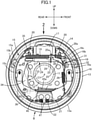
- a drum brake B is provided in a wheel (for example, the left rear wheel) of a four-wheeled vehicle.
- This drum brake B includes a fixed back plate 13 having a through-hole 12, at the central portion thereof, through which an axle shaft 11 of the left rear wheel penetrates, first and second brake shoes 15 and 16 disposed in the back plate 13 so as to make slidable contact with the inner circumference of a brake drum 14 that rotates together with the left rear wheel, a wheel cylinder 17 fixed to the back plate 13 so as to exert a force for expanding the first and second brake shoes 15 and 16, automatic braking gap adjustment means (so-called automatic adjuster) 18 that automatically adjusts the gap between the first and second brake shoes 15 and 16 and the brake drum 14, and return springs 19 disposed between the first and second brake shoes 15 and 16.
- automatic braking gap adjustment means so-called automatic adjuster 18 that automatically adjusts the gap between the first and second brake shoes 15 and 16 and the brake drum 14, and return springs 19 disposed between the first and second brake shoes 15 and 16.
- the first and second brake shoes 15 and 16 include first and second webs 15a and 16a formed in bow-shaped flat plates along the inner circumference of the brake drum 14, first and second rims 15b and 16b consecutively provided orthogonally to the outer circumferences of the first and second webs 15a and 16a, and first and second linings 15c and 16c pasted to the outer circumferences of the first and second rims 15b and 16b.
- the wheel cylinder 17 is operated by the output hydraulic pressure of a master cylinder (not illustrated) operated by a brake pedal and fixed to the back plate 13 at a position between the other end portions of the first and second brake shoes 15 and 16 so as to exert a force for expanding the first and second brake shoes 15 and 16 using the anchor plate 21 as the fulcrums, and the outer end portions of a pair of pistons 20 of this wheel cylinder 17 are disposed so as to face the other end portions (upper end portions in this embodiment) of the first and second webs 15a and 16a.
- a coil spring 22 for biasing the one end portions of the first and second webs 15a and 16a toward the anchor plate 21 is provided between the one end portions of the first and second webs 15a and 16a, and the pair of return springs 19 for biasing the first and second brake shoes 15 and 16 in the contraction direction are provided between the other end portions of the first and second webs 15a and 16a.
- the automatic braking gap adjustment means 18 is provided between the first and second webs 15a and 16a of the first and second brake shoes 15 and 16 and includes a contraction position regulation strut 24 capable of extending by the pivot of an adjustment gear 23, an adjustment lever 25, which has a feed claw 25a engaging with the adjustment gear 23 and is pivotably supported by the second web 16a of the second brake shoe 16 of the first and second brake shoes 15 and 16, and an adjustment spring 26, which biases the adjustment lever 25 to pivot so that the adjustment gear 23 pivots in a direction in which the contraction position regulation strut 24 is extended.
- the contraction position regulation strut 24 regulates the contraction positions of the first and second brake shoes 15 and 16 and includes a first rod 27 having a first engaging connection portion 27a that engages with the portion of the first web 15a of the brake shoe 15 of the first and second brake shoes 15 and 16 close to the other end portion, a second rod 28 that has a second engaging connection portion 28a engaging with the portion of the second web 16a of the second brake shoe 16 close to the other end portion and is disposed coaxially with the first rod 27, and an adjustment bolt 29 that has one end portion to be inserted into the first rod 27 relatively movably in the axial direction and the other end portion to be screwed coaxially with the second rod 28, in which the adjustment gear 23 is disposed between the first and second rods 27 and 28 and formed on the outer circumference of the adjusting bolt 29.
- a first locking recess 30 with which the first engaging connection portion 27a engages is provided in the side edge that faces the axle shaft 11 close to the other end portion of the first web 15a and a second locking recess 31 with which the second engaging connection portion 28a engages is provided in the side edge that faces the axle shaft 11 close to the other end portion of the second web 16a.
- the adjustment lever 25 having the feed claw 25a that engages with the adjustment gear 23 is pivotably supported by the second web 16a via a support shaft 32, and the adjustment spring 26 is provided between the second web 16a and the adjustment lever 25. Moreover, the spring force of the adjustment spring 26 is set smaller than the spring force of the return spring 19.
- the adjustment lever 25 pivots about the axis line of the support shaft 32 due to the spring force of the adjustment spring 26 and the adjustment gear 23 pivots, whereby the effective length of the contraction position regulation strut 24 is increased.
- a parking brake mechanism 33 capable of generating a parking brake force is provided in the back plate 13 of this drum brake B, and the parking brake mechanism 33 includes the first and second brake shoes 15 and 16, which can make slidable contact with the inner circumference of the brake drum 14 and a parking brake lever 34 as the parking brake operator to be pivotably connected to the first brake shoe 15.
- the parking brake lever 34 is disposed so as to overlap with a part of the first web 15a of the first brake shoe 15 in front view seen in a direction (direction illustrated in Fig. 1 ) along the rotation axis line of the brake drum 14 and the parking brake lever 34 extends long in the longitudinal direction of first web 15a.
- the parking brake lever 34 When the parking brake of the vehicle operates, the parking brake lever 34 is pivoted and driven in the counterclockwise direction illustrated in Fig. 1 using the pin 35 as a fulcrum by receiving the power input from an electric actuator 38 (see Figs. 2 and 3 ) via the brake cable 37, and the pivot of the parking brake lever 34 applies, to the second brake sue 16, a force in a direction in which the second lining 16c of the second brake shoe 16 is pressed against the inner circumference of the brake drum 14 via the contraction position regulation strut 24. Furthermore, when the parking brake lever 34 is continuously pivoted and driven in the counterclockwise direction illustrated in Fig.
- the parking brake lever 34 is pivoted using the engaging portion with respect to the first engaging connection portion 27a of the contraction position regulation strut 24 as a fulcrum, the first brake shoe 15 is extended via the pin 35, and the first lining 15c of the first brake shoe 15 is pressed against the inner circumference of the brake drum 14. That is, the parking brake lever 34 operates at an operating position at which the first and second linings 15c and 16c of the first and second brake shoes 15 and 16 are pressed against the inner circumference of the brake drum 14 and the parking brake state is obtained in this state.
- the parking brake lever 34 when the application of the pivot driving force to the parking brake lever 34 is stopped by loosening the brake cable 37, the parking brake lever 34 returns to the non-operating position together with the first and second brake shoes 15 and 16 operated in a direction away from the inner circumference of the brake drum 14 by the spring force of the return spring 19.
- the brake cable 37 can receive the power from the electric actuator 38 fixedly disposed outside the back plate 13 and is towed by the power generated by the electric actuator 38.
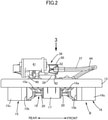
- the electric actuator 38 includes a screw shaft 39 as an output member to be connected to the brake cable 37, an actuator case 40 that supports the screw shaft 39 so as to enable reciprocating motion in the axis line direction while blocking the rotation thereof, an electric motor 41 supported by the actuator case 40 so as to be rotatable forward and backward, and a motion conversion mechanism (not illustrated) that is disposed between the electric motor 41 and the shaft 39 and housed in the actuator case 40 while enabling conversion of the rotational motion generated by the electric motor 41 into the linear motion of the screw shaft 39.
- the actuator case 40 of the electric actuator 38 is disposed above a rotating center C1 of the wheel, that is, the center of the axle shaft 11 with the drum brake B mounted to the wheel.
- the actuator case 40 disposed above a virtual horizontal plane IH passing through the rotating center C1 is mounted on the back plate 13 via an installation member 42 on the opposite side of the wheel cylinder 17.
- the installation member 42 is fixed to the actuator case 40 and the installation member 42 is fastened to the back plate 13 via a plurality of, for example, three bolts 43.
- the actuator case 40 is disposed at a position inside an outermost circumference 13a of the back plate 13 as clearly illustrated in Fig. 3 in side view seen in a direction parallel to the rotating center C1 of the wheel.
- the electric actuator 38 is mounted on the back plate 13 so that an operating axis line C2 of the screw shaft 39, which is an output member, that is, the axis line of the screw shaft 38 is aligned with the vehicle front-rear direction.
- At least the portion of the brake cable 37 that is routed outside the back plate 13 is covered with a cylindrical member and, in this embodiment, at least the portion of the brake cable 37 that is routed outside the back plate 13 is covered with an outer cable 44, which is a cylindrical member formed by, for example, winding an iron wire member into a coil.
- the cylindrical member only needs to be a member that can receive a reaction force due to the output of the electric actuator 38 and may be a metal cylinder member instead of the outer cable 44 described above.
- the screw shaft 39 of the electric actuator 38 is connected to the brake cable 37 via a cable joint 51 and the end portion of the outer cable 44 close to the electric actuator 38 is attached, via a guide tube 52, to a protect cylinder 50 to be mounted on the actuator case 40 so as to cover the connection portion between the screw shaft 39 and the brake cable 37.
- a cylindrical portion 13b projects integrally in the front portion along the vehicle front-rear direction in the lower portion of the back plate 13, and the brake cable 37 covered with the outer cable 44 is introduced into the back plate 13 through an introduction hole 53 provided in the cylindrical portion 13b and routed at a position below the axle shaft 11 so as to be present at a position below the rotating center C1 of the wheel in the back plate 13 with the drum brake B mounted to the wheel.
- the portion of the brake cable 37 disposed in the back plate 13 extends in the tangent direction of the pivot direction of the parking brake lever 34, which is pivotably connected to the first web 15a of the first brake shoe 15 via the pin 35, and connected to the parking brake lever 34, and at least the portion of the brake cable 37 disposed outside the back plate 13 is bent and routed and connected to the electric actuator 38 mounted on the back plate 13 above the virtual horizontal plane IH passing through the rotating center C1 of the wheel.
- a holding plate 45 that sandwiches the anchor plate 21 between the holding plate 45 and the back plate 13 is attached to the lower portion of the back plate 13 by a pair of rivets 47 together with the anchor plate 21, and a guide portion 45a for guiding the brake cable 37 together with the outer cable 44 is provided integrally on the holding plate 45 so as to have a substantially U-shaped cross section.
- the parking brake mechanism 33 provided in the back plate 13 of the drum brake B so as to enable the generation of a parking brake force includes the parking brake lever 34, which is a parking brake operator pivoting by receiving the power from the electric actuator 38, at least the portion of the break cable 37 disposed in the back plate 13, which is the link means provided between the electric actuator 38 and the parking brake lever 34 to transmit the power from the electric actuator 38, extends in the tangent direction of the pivot direction of the parking brake lever 34 and is connected to the parking brake lever 34, and at least the portion of the break cable 37 disposed outside the back plate 13 is bent and connected to the electric actuator 38. Accordingly, the back plate 13 and the brake cable 37 can follow the conventional concept of a non-electric parking brake device, so the electric parking brake device with a simple and easy structure can be configured.
- connection between the parking brake lever 34 and the electric actuator 38 can be easily made while the brake cable 37 is easily routed.
- the actuator case 40 is disposed at a position inside the outermost circumference 13a of the back plate 13 in side view seen in a direction parallel to the rotating center C1 of the wheel, the possibility that the actuator case 40 is attacked by external factors during travel of the vehicle can be reduced.
- the brake cable 37 can be easily routed.
- the actuator case 40 is mounted on the back plate 13, the actuator case 40 can be easily mounted.
- the outer cable 44 which is a cylindrical member, the flexibility in the routing of the brake cable 37 is increased.
- the actuator case 40 of the electric actuator 38 is mounted on the back plate 13 in the embodiment described above, but the actuator case 40 may be mounted to the undercarriage component of the vehicle.
- the present invention is also applicable to an electric parking brake device in which the back plate does not have the through-hole through which the axle shaft penetrates and the back plate is mounted to the wheel hub.
Landscapes
- Engineering & Computer Science (AREA)
- General Engineering & Computer Science (AREA)
- Mechanical Engineering (AREA)
- Transportation (AREA)
- Braking Arrangements (AREA)
- Braking Systems And Boosters (AREA)
Applications Claiming Priority (2)
| Application Number | Priority Date | Filing Date | Title |
|---|---|---|---|
| JP2019058096 | 2019-03-26 | ||
| PCT/JP2020/011133 WO2020195961A1 (ja) | 2019-03-26 | 2020-03-13 | 電動パーキングブレーキ装置 |
Publications (3)
| Publication Number | Publication Date |
|---|---|
| EP3951206A1 true EP3951206A1 (de) | 2022-02-09 |
| EP3951206A4 EP3951206A4 (de) | 2023-02-22 |
| EP3951206B1 EP3951206B1 (de) | 2024-05-08 |
Family
ID=72611429
Family Applications (1)
| Application Number | Title | Priority Date | Filing Date |
|---|---|---|---|
| EP20779451.2A Active EP3951206B1 (de) | 2019-03-26 | 2020-03-13 | Elektrische feststellbremsenvorrichtung |
Country Status (4)
| Country | Link |
|---|---|
| EP (1) | EP3951206B1 (de) |
| JP (1) | JP7451496B2 (de) |
| CN (1) | CN113518869A (de) |
| WO (1) | WO2020195961A1 (de) |
Families Citing this family (1)
| Publication number | Priority date | Publication date | Assignee | Title |
|---|---|---|---|---|
| CN116658543B (zh) * | 2023-06-01 | 2025-09-02 | 海盐欧亚特汽配有限公司 | 一种快速贴合制动鼓的刹车片安装结构 |
Family Cites Families (10)
| Publication number | Priority date | Publication date | Assignee | Title |
|---|---|---|---|---|
| JP3708011B2 (ja) * | 2000-09-13 | 2005-10-19 | トヨタ自動車株式会社 | 車両用ブレーキの制御装置 |
| JP2010241271A (ja) * | 2009-04-06 | 2010-10-28 | Toyota Motor Corp | ブレーキ制御装置 |
| JP2015110967A (ja) | 2013-12-06 | 2015-06-18 | 曙ブレーキ工業株式会社 | ドラム式電動駐車ブレーキ装置用アクチュエータユニット |
| EP3163113B1 (de) | 2014-06-26 | 2020-06-03 | Akebono Brake Industry Co., Ltd. | Trommelbremsvorrichtung |
| FR3029874B1 (fr) * | 2014-12-11 | 2016-12-23 | Foundation Brakes France | Actionneur electrique pour levier de frein de parking au sein d'un frein a tambour |
| JP6472287B2 (ja) * | 2015-03-20 | 2019-02-20 | 日信工業株式会社 | 車両用ブレーキ装置 |
| JP6472288B2 (ja) * | 2015-03-20 | 2019-02-20 | 日信工業株式会社 | 車両用ブレーキ装置 |
| JP6537468B2 (ja) * | 2016-03-31 | 2019-07-03 | 株式会社アドヴィックス | 車両用ブレーキ |
| JP2018021575A (ja) * | 2016-08-01 | 2018-02-08 | アスモ株式会社 | 電動パーキングブレーキ装置 |
| JP2018173104A (ja) * | 2017-03-31 | 2018-11-08 | 豊生ブレーキ工業株式会社 | 電動式ドラムブレーキ |
-
2020
- 2020-03-13 CN CN202080018400.9A patent/CN113518869A/zh active Pending
- 2020-03-13 EP EP20779451.2A patent/EP3951206B1/de active Active
- 2020-03-13 WO PCT/JP2020/011133 patent/WO2020195961A1/ja not_active Ceased
- 2020-03-13 JP JP2021509052A patent/JP7451496B2/ja active Active
Also Published As
| Publication number | Publication date |
|---|---|
| JPWO2020195961A1 (de) | 2020-10-01 |
| JP7451496B2 (ja) | 2024-03-18 |
| CN113518869A (zh) | 2021-10-19 |
| WO2020195961A1 (ja) | 2020-10-01 |
| EP3951206B1 (de) | 2024-05-08 |
| EP3951206A4 (de) | 2023-02-22 |
Similar Documents
| Publication | Publication Date | Title |
|---|---|---|
| US10138966B2 (en) | Vehicle brake apparatus | |
| EP3951206B1 (de) | Elektrische feststellbremsenvorrichtung | |
| US5360086A (en) | Drum brake with cam operated parking brake lever | |
| US3498419A (en) | Mechanical actuating means for internal-expansion brakes | |
| JP2020051519A (ja) | 車両用ブレーキ装置 | |
| JP6157384B2 (ja) | 車両用ブレーキ装置 | |
| US20050145451A1 (en) | Adapter for vehicle brake assembly | |
| CN114127435B (zh) | 车辆用鼓式制动器 | |
| KR20060063092A (ko) | 차량용 드럼브레이크시스템 | |
| WO2020004524A1 (ja) | ブレーキ装置 | |
| US12491855B2 (en) | Electric parking brake device for vehicle | |
| JP7037518B2 (ja) | 車両用ドラムブレーキ | |
| US1966140A (en) | Brake | |
| JP6268594B2 (ja) | 車両用ブレーキ装置 | |
| US1790672A (en) | lyford | |
| US1339895A (en) | Brake mechanism for automobiles | |
| KR19990032143U (ko) | 차량용 브레이크장치의 드럼브레이크 | |
| KR100931490B1 (ko) | 드럼 브레이크 | |
| JPH066297Y2 (ja) | パーキングブレーキ付き車両用ドラムブレーキ | |
| KR20050105332A (ko) | 차량용 드럼브레이크시스템 | |
| KR20050105892A (ko) | 차량용 드럼브레이크시스템 | |
| JP2015187463A (ja) | 車両用ブレーキ装置 | |
| KR20040071877A (ko) | 드럼브레이크 | |
| KR20190049245A (ko) | 자동차용 bir타입 브레이크 캘리퍼 | |
| JP2017155844A (ja) | パーキングブレーキの取付構造 |
Legal Events
| Date | Code | Title | Description |
|---|---|---|---|
| STAA | Information on the status of an ep patent application or granted ep patent |
Free format text: STATUS: THE INTERNATIONAL PUBLICATION HAS BEEN MADE |
|
| PUAI | Public reference made under article 153(3) epc to a published international application that has entered the european phase |
Free format text: ORIGINAL CODE: 0009012 |
|
| STAA | Information on the status of an ep patent application or granted ep patent |
Free format text: STATUS: REQUEST FOR EXAMINATION WAS MADE |
|
| 17P | Request for examination filed |
Effective date: 20211014 |
|
| AK | Designated contracting states |
Kind code of ref document: A1 Designated state(s): AL AT BE BG CH CY CZ DE DK EE ES FI FR GB GR HR HU IE IS IT LI LT LU LV MC MK MT NL NO PL PT RO RS SE SI SK SM TR |
|
| DAV | Request for validation of the european patent (deleted) | ||
| DAX | Request for extension of the european patent (deleted) | ||
| A4 | Supplementary search report drawn up and despatched |
Effective date: 20230120 |
|
| RIC1 | Information provided on ipc code assigned before grant |
Ipc: B60T 13/74 20060101ALI20230116BHEP Ipc: F16D 125/60 20120101ALI20230116BHEP Ipc: F16D 121/24 20120101ALI20230116BHEP Ipc: F16D 65/22 20060101ALI20230116BHEP Ipc: F16D 65/09 20060101ALI20230116BHEP Ipc: F16D 51/22 20060101AFI20230116BHEP |
|
| GRAP | Despatch of communication of intention to grant a patent |
Free format text: ORIGINAL CODE: EPIDOSNIGR1 |
|
| STAA | Information on the status of an ep patent application or granted ep patent |
Free format text: STATUS: GRANT OF PATENT IS INTENDED |
|
| INTG | Intention to grant announced |
Effective date: 20231204 |
|
| GRAS | Grant fee paid |
Free format text: ORIGINAL CODE: EPIDOSNIGR3 |
|
| GRAA | (expected) grant |
Free format text: ORIGINAL CODE: 0009210 |
|
| STAA | Information on the status of an ep patent application or granted ep patent |
Free format text: STATUS: THE PATENT HAS BEEN GRANTED |
|
| AK | Designated contracting states |
Kind code of ref document: B1 Designated state(s): AL AT BE BG CH CY CZ DE DK EE ES FI FR GB GR HR HU IE IS IT LI LT LU LV MC MK MT NL NO PL PT RO RS SE SI SK SM TR |
|
| REG | Reference to a national code |
Ref country code: GB Ref legal event code: FG4D |
|
| REG | Reference to a national code |
Ref country code: CH Ref legal event code: EP |
|
| REG | Reference to a national code |
Ref country code: DE Ref legal event code: R096 Ref document number: 602020030681 Country of ref document: DE |
|
| REG | Reference to a national code |
Ref country code: IE Ref legal event code: FG4D |
|
| REG | Reference to a national code |
Ref country code: LT Ref legal event code: MG9D |
|
| REG | Reference to a national code |
Ref country code: NL Ref legal event code: MP Effective date: 20240508 |
|
| PG25 | Lapsed in a contracting state [announced via postgrant information from national office to epo] |
Ref country code: IS Free format text: LAPSE BECAUSE OF FAILURE TO SUBMIT A TRANSLATION OF THE DESCRIPTION OR TO PAY THE FEE WITHIN THE PRESCRIBED TIME-LIMIT Effective date: 20240908 |
|
| PG25 | Lapsed in a contracting state [announced via postgrant information from national office to epo] |
Ref country code: BG Free format text: LAPSE BECAUSE OF FAILURE TO SUBMIT A TRANSLATION OF THE DESCRIPTION OR TO PAY THE FEE WITHIN THE PRESCRIBED TIME-LIMIT Effective date: 20240508 |
|
| PG25 | Lapsed in a contracting state [announced via postgrant information from national office to epo] |
Ref country code: HR Free format text: LAPSE BECAUSE OF FAILURE TO SUBMIT A TRANSLATION OF THE DESCRIPTION OR TO PAY THE FEE WITHIN THE PRESCRIBED TIME-LIMIT Effective date: 20240508 Ref country code: FI Free format text: LAPSE BECAUSE OF FAILURE TO SUBMIT A TRANSLATION OF THE DESCRIPTION OR TO PAY THE FEE WITHIN THE PRESCRIBED TIME-LIMIT Effective date: 20240508 |
|
| PG25 | Lapsed in a contracting state [announced via postgrant information from national office to epo] |
Ref country code: GR Free format text: LAPSE BECAUSE OF FAILURE TO SUBMIT A TRANSLATION OF THE DESCRIPTION OR TO PAY THE FEE WITHIN THE PRESCRIBED TIME-LIMIT Effective date: 20240809 |
|
| PG25 | Lapsed in a contracting state [announced via postgrant information from national office to epo] |
Ref country code: PT Free format text: LAPSE BECAUSE OF FAILURE TO SUBMIT A TRANSLATION OF THE DESCRIPTION OR TO PAY THE FEE WITHIN THE PRESCRIBED TIME-LIMIT Effective date: 20240909 |
|
| REG | Reference to a national code |
Ref country code: AT Ref legal event code: MK05 Ref document number: 1685223 Country of ref document: AT Kind code of ref document: T Effective date: 20240508 |
|
| PG25 | Lapsed in a contracting state [announced via postgrant information from national office to epo] |
Ref country code: NL Free format text: LAPSE BECAUSE OF FAILURE TO SUBMIT A TRANSLATION OF THE DESCRIPTION OR TO PAY THE FEE WITHIN THE PRESCRIBED TIME-LIMIT Effective date: 20240508 |
|
| PG25 | Lapsed in a contracting state [announced via postgrant information from national office to epo] |
Ref country code: ES Free format text: LAPSE BECAUSE OF FAILURE TO SUBMIT A TRANSLATION OF THE DESCRIPTION OR TO PAY THE FEE WITHIN THE PRESCRIBED TIME-LIMIT Effective date: 20240508 |
|
| PG25 | Lapsed in a contracting state [announced via postgrant information from national office to epo] |
Ref country code: AT Free format text: LAPSE BECAUSE OF FAILURE TO SUBMIT A TRANSLATION OF THE DESCRIPTION OR TO PAY THE FEE WITHIN THE PRESCRIBED TIME-LIMIT Effective date: 20240508 |
|
| PG25 | Lapsed in a contracting state [announced via postgrant information from national office to epo] |
Ref country code: PL Free format text: LAPSE BECAUSE OF FAILURE TO SUBMIT A TRANSLATION OF THE DESCRIPTION OR TO PAY THE FEE WITHIN THE PRESCRIBED TIME-LIMIT Effective date: 20240508 |
|
| PG25 | Lapsed in a contracting state [announced via postgrant information from national office to epo] |
Ref country code: LV Free format text: LAPSE BECAUSE OF FAILURE TO SUBMIT A TRANSLATION OF THE DESCRIPTION OR TO PAY THE FEE WITHIN THE PRESCRIBED TIME-LIMIT Effective date: 20240508 |
|
| PG25 | Lapsed in a contracting state [announced via postgrant information from national office to epo] |
Ref country code: PT Free format text: LAPSE BECAUSE OF FAILURE TO SUBMIT A TRANSLATION OF THE DESCRIPTION OR TO PAY THE FEE WITHIN THE PRESCRIBED TIME-LIMIT Effective date: 20240909 Ref country code: PL Free format text: LAPSE BECAUSE OF FAILURE TO SUBMIT A TRANSLATION OF THE DESCRIPTION OR TO PAY THE FEE WITHIN THE PRESCRIBED TIME-LIMIT Effective date: 20240508 Ref country code: NO Free format text: LAPSE BECAUSE OF FAILURE TO SUBMIT A TRANSLATION OF THE DESCRIPTION OR TO PAY THE FEE WITHIN THE PRESCRIBED TIME-LIMIT Effective date: 20240808 Ref country code: NL Free format text: LAPSE BECAUSE OF FAILURE TO SUBMIT A TRANSLATION OF THE DESCRIPTION OR TO PAY THE FEE WITHIN THE PRESCRIBED TIME-LIMIT Effective date: 20240508 Ref country code: LV Free format text: LAPSE BECAUSE OF FAILURE TO SUBMIT A TRANSLATION OF THE DESCRIPTION OR TO PAY THE FEE WITHIN THE PRESCRIBED TIME-LIMIT Effective date: 20240508 Ref country code: IS Free format text: LAPSE BECAUSE OF FAILURE TO SUBMIT A TRANSLATION OF THE DESCRIPTION OR TO PAY THE FEE WITHIN THE PRESCRIBED TIME-LIMIT Effective date: 20240908 Ref country code: HR Free format text: LAPSE BECAUSE OF FAILURE TO SUBMIT A TRANSLATION OF THE DESCRIPTION OR TO PAY THE FEE WITHIN THE PRESCRIBED TIME-LIMIT Effective date: 20240508 Ref country code: GR Free format text: LAPSE BECAUSE OF FAILURE TO SUBMIT A TRANSLATION OF THE DESCRIPTION OR TO PAY THE FEE WITHIN THE PRESCRIBED TIME-LIMIT Effective date: 20240809 Ref country code: FI Free format text: LAPSE BECAUSE OF FAILURE TO SUBMIT A TRANSLATION OF THE DESCRIPTION OR TO PAY THE FEE WITHIN THE PRESCRIBED TIME-LIMIT Effective date: 20240508 Ref country code: ES Free format text: LAPSE BECAUSE OF FAILURE TO SUBMIT A TRANSLATION OF THE DESCRIPTION OR TO PAY THE FEE WITHIN THE PRESCRIBED TIME-LIMIT Effective date: 20240508 Ref country code: BG Free format text: LAPSE BECAUSE OF FAILURE TO SUBMIT A TRANSLATION OF THE DESCRIPTION OR TO PAY THE FEE WITHIN THE PRESCRIBED TIME-LIMIT Effective date: 20240508 Ref country code: AT Free format text: LAPSE BECAUSE OF FAILURE TO SUBMIT A TRANSLATION OF THE DESCRIPTION OR TO PAY THE FEE WITHIN THE PRESCRIBED TIME-LIMIT Effective date: 20240508 Ref country code: RS Free format text: LAPSE BECAUSE OF FAILURE TO SUBMIT A TRANSLATION OF THE DESCRIPTION OR TO PAY THE FEE WITHIN THE PRESCRIBED TIME-LIMIT Effective date: 20240808 |
|
| PG25 | Lapsed in a contracting state [announced via postgrant information from national office to epo] |
Ref country code: DK Free format text: LAPSE BECAUSE OF FAILURE TO SUBMIT A TRANSLATION OF THE DESCRIPTION OR TO PAY THE FEE WITHIN THE PRESCRIBED TIME-LIMIT Effective date: 20240508 |
|
| PG25 | Lapsed in a contracting state [announced via postgrant information from national office to epo] |
Ref country code: EE Free format text: LAPSE BECAUSE OF FAILURE TO SUBMIT A TRANSLATION OF THE DESCRIPTION OR TO PAY THE FEE WITHIN THE PRESCRIBED TIME-LIMIT Effective date: 20240508 |
|
| PG25 | Lapsed in a contracting state [announced via postgrant information from national office to epo] |
Ref country code: CZ Free format text: LAPSE BECAUSE OF FAILURE TO SUBMIT A TRANSLATION OF THE DESCRIPTION OR TO PAY THE FEE WITHIN THE PRESCRIBED TIME-LIMIT Effective date: 20240508 |
|
| PG25 | Lapsed in a contracting state [announced via postgrant information from national office to epo] |
Ref country code: SK Free format text: LAPSE BECAUSE OF FAILURE TO SUBMIT A TRANSLATION OF THE DESCRIPTION OR TO PAY THE FEE WITHIN THE PRESCRIBED TIME-LIMIT Effective date: 20240508 Ref country code: RO Free format text: LAPSE BECAUSE OF FAILURE TO SUBMIT A TRANSLATION OF THE DESCRIPTION OR TO PAY THE FEE WITHIN THE PRESCRIBED TIME-LIMIT Effective date: 20240508 |
|
| PG25 | Lapsed in a contracting state [announced via postgrant information from national office to epo] |
Ref country code: SM Free format text: LAPSE BECAUSE OF FAILURE TO SUBMIT A TRANSLATION OF THE DESCRIPTION OR TO PAY THE FEE WITHIN THE PRESCRIBED TIME-LIMIT Effective date: 20240508 |
|
| PG25 | Lapsed in a contracting state [announced via postgrant information from national office to epo] |
Ref country code: SM Free format text: LAPSE BECAUSE OF FAILURE TO SUBMIT A TRANSLATION OF THE DESCRIPTION OR TO PAY THE FEE WITHIN THE PRESCRIBED TIME-LIMIT Effective date: 20240508 Ref country code: SK Free format text: LAPSE BECAUSE OF FAILURE TO SUBMIT A TRANSLATION OF THE DESCRIPTION OR TO PAY THE FEE WITHIN THE PRESCRIBED TIME-LIMIT Effective date: 20240508 Ref country code: RO Free format text: LAPSE BECAUSE OF FAILURE TO SUBMIT A TRANSLATION OF THE DESCRIPTION OR TO PAY THE FEE WITHIN THE PRESCRIBED TIME-LIMIT Effective date: 20240508 Ref country code: EE Free format text: LAPSE BECAUSE OF FAILURE TO SUBMIT A TRANSLATION OF THE DESCRIPTION OR TO PAY THE FEE WITHIN THE PRESCRIBED TIME-LIMIT Effective date: 20240508 Ref country code: DK Free format text: LAPSE BECAUSE OF FAILURE TO SUBMIT A TRANSLATION OF THE DESCRIPTION OR TO PAY THE FEE WITHIN THE PRESCRIBED TIME-LIMIT Effective date: 20240508 Ref country code: CZ Free format text: LAPSE BECAUSE OF FAILURE TO SUBMIT A TRANSLATION OF THE DESCRIPTION OR TO PAY THE FEE WITHIN THE PRESCRIBED TIME-LIMIT Effective date: 20240508 |
|
| REG | Reference to a national code |
Ref country code: DE Ref legal event code: R097 Ref document number: 602020030681 Country of ref document: DE |
|
| PLBE | No opposition filed within time limit |
Free format text: ORIGINAL CODE: 0009261 |
|
| STAA | Information on the status of an ep patent application or granted ep patent |
Free format text: STATUS: NO OPPOSITION FILED WITHIN TIME LIMIT |
|
| 26N | No opposition filed |
Effective date: 20250211 |
|
| PG25 | Lapsed in a contracting state [announced via postgrant information from national office to epo] |
Ref country code: SI Free format text: LAPSE BECAUSE OF FAILURE TO SUBMIT A TRANSLATION OF THE DESCRIPTION OR TO PAY THE FEE WITHIN THE PRESCRIBED TIME-LIMIT Effective date: 20240508 |
|
| PG25 | Lapsed in a contracting state [announced via postgrant information from national office to epo] |
Ref country code: SE Free format text: LAPSE BECAUSE OF FAILURE TO SUBMIT A TRANSLATION OF THE DESCRIPTION OR TO PAY THE FEE WITHIN THE PRESCRIBED TIME-LIMIT Effective date: 20240508 |
|
| PG25 | Lapsed in a contracting state [announced via postgrant information from national office to epo] |
Ref country code: MC Free format text: LAPSE BECAUSE OF FAILURE TO SUBMIT A TRANSLATION OF THE DESCRIPTION OR TO PAY THE FEE WITHIN THE PRESCRIBED TIME-LIMIT Effective date: 20240508 |
|
| REG | Reference to a national code |
Ref country code: CH Ref legal event code: H13 Free format text: ST27 STATUS EVENT CODE: U-0-0-H10-H13 (AS PROVIDED BY THE NATIONAL OFFICE) Effective date: 20251023 |
|
| PG25 | Lapsed in a contracting state [announced via postgrant information from national office to epo] |
Ref country code: LU Free format text: LAPSE BECAUSE OF NON-PAYMENT OF DUE FEES Effective date: 20250313 |
|
| REG | Reference to a national code |
Ref country code: BE Ref legal event code: MM Effective date: 20250331 |
|
| PG25 | Lapsed in a contracting state [announced via postgrant information from national office to epo] |
Ref country code: BE Free format text: LAPSE BECAUSE OF NON-PAYMENT OF DUE FEES Effective date: 20250331 |
|
| PG25 | Lapsed in a contracting state [announced via postgrant information from national office to epo] |
Ref country code: CH Free format text: LAPSE BECAUSE OF NON-PAYMENT OF DUE FEES Effective date: 20250331 |
|
| PG25 | Lapsed in a contracting state [announced via postgrant information from national office to epo] |
Ref country code: IE Free format text: LAPSE BECAUSE OF NON-PAYMENT OF DUE FEES Effective date: 20250313 |
|
| PGFP | Annual fee paid to national office [announced via postgrant information from national office to epo] |
Ref country code: GB Payment date: 20260202 Year of fee payment: 7 |
|
| PGFP | Annual fee paid to national office [announced via postgrant information from national office to epo] |
Ref country code: DE Payment date: 20260128 Year of fee payment: 7 |
|
| PGFP | Annual fee paid to national office [announced via postgrant information from national office to epo] |
Ref country code: IT Payment date: 20260220 Year of fee payment: 7 |
|
| PGFP | Annual fee paid to national office [announced via postgrant information from national office to epo] |
Ref country code: FR Payment date: 20260209 Year of fee payment: 7 |