EP3951224B1 - Flüssigkeitsabgabevorrichtung mit sicherheitsventil - Google Patents
Flüssigkeitsabgabevorrichtung mit sicherheitsventil Download PDFInfo
- Publication number
- EP3951224B1 EP3951224B1 EP21189196.5A EP21189196A EP3951224B1 EP 3951224 B1 EP3951224 B1 EP 3951224B1 EP 21189196 A EP21189196 A EP 21189196A EP 3951224 B1 EP3951224 B1 EP 3951224B1
- Authority
- EP
- European Patent Office
- Prior art keywords
- shutter
- valve seat
- fluid
- outlet opening
- opening
- Prior art date
- Legal status (The legal status is an assumption and is not a legal conclusion. Google has not performed a legal analysis and makes no representation as to the accuracy of the status listed.)
- Active
Links
Images


Classifications
-
- F—MECHANICAL ENGINEERING; LIGHTING; HEATING; WEAPONS; BLASTING
- F16—ENGINEERING ELEMENTS AND UNITS; GENERAL MEASURES FOR PRODUCING AND MAINTAINING EFFECTIVE FUNCTIONING OF MACHINES OR INSTALLATIONS; THERMAL INSULATION IN GENERAL
- F16K—VALVES; TAPS; COCKS; ACTUATING-FLOATS; DEVICES FOR VENTING OR AERATING
- F16K17/00—Safety valves; Equalising valves, e.g. pressure relief valves
- F16K17/02—Safety valves; Equalising valves, e.g. pressure relief valves opening on surplus pressure on one side; closing on insufficient pressure on one side
- F16K17/04—Safety valves; Equalising valves, e.g. pressure relief valves opening on surplus pressure on one side; closing on insufficient pressure on one side spring-loaded
-
- B—PERFORMING OPERATIONS; TRANSPORTING
- B05—SPRAYING OR ATOMISING IN GENERAL; APPLYING FLUENT MATERIALS TO SURFACES, IN GENERAL
- B05B—SPRAYING APPARATUS; ATOMISING APPARATUS; NOZZLES
- B05B1/00—Nozzles, spray heads or other outlets, with or without auxiliary devices such as valves, heating means
- B05B1/30—Nozzles, spray heads or other outlets, with or without auxiliary devices such as valves, heating means designed to control volume of flow, e.g. with adjustable passages
- B05B1/3006—Nozzles, spray heads or other outlets, with or without auxiliary devices such as valves, heating means designed to control volume of flow, e.g. with adjustable passages the controlling element being actuated by the pressure of the fluid to be sprayed
-
- B—PERFORMING OPERATIONS; TRANSPORTING
- B05—SPRAYING OR ATOMISING IN GENERAL; APPLYING FLUENT MATERIALS TO SURFACES, IN GENERAL
- B05B—SPRAYING APPARATUS; ATOMISING APPARATUS; NOZZLES
- B05B15/00—Details of spraying plant or spraying apparatus not otherwise provided for; Accessories
- B05B15/14—Arrangements for preventing or controlling structural damage to spraying apparatus or its outlets, e.g. for breaking at desired places; Arrangements for handling or replacing damaged parts
-
- E—FIXED CONSTRUCTIONS
- E03—WATER SUPPLY; SEWERAGE
- E03C—DOMESTIC PLUMBING INSTALLATIONS FOR FRESH WATER OR WASTE WATER; SINKS
- E03C1/00—Domestic plumbing installations for fresh water or waste water; Sinks
- E03C1/02—Plumbing installations for fresh water
- E03C1/08—Jet regulators or jet guides, e.g. anti-splash devices
- E03C1/084—Jet regulators with aerating means
-
- E—FIXED CONSTRUCTIONS
- E03—WATER SUPPLY; SEWERAGE
- E03C—DOMESTIC PLUMBING INSTALLATIONS FOR FRESH WATER OR WASTE WATER; SINKS
- E03C1/00—Domestic plumbing installations for fresh water or waste water; Sinks
- E03C1/02—Plumbing installations for fresh water
- E03C1/10—Devices for preventing contamination of drinking-water pipes, e.g. means for aerating self-closing flushing valves
- E03C1/104—Devices for preventing contamination of drinking-water pipes, e.g. means for aerating self-closing flushing valves using a single check valve
-
- F—MECHANICAL ENGINEERING; LIGHTING; HEATING; WEAPONS; BLASTING
- F16—ENGINEERING ELEMENTS AND UNITS; GENERAL MEASURES FOR PRODUCING AND MAINTAINING EFFECTIVE FUNCTIONING OF MACHINES OR INSTALLATIONS; THERMAL INSULATION IN GENERAL
- F16K—VALVES; TAPS; COCKS; ACTUATING-FLOATS; DEVICES FOR VENTING OR AERATING
- F16K15/00—Check valves
- F16K15/02—Check valves with guided rigid valve members
- F16K15/06—Check valves with guided rigid valve members with guided stems
- F16K15/063—Check valves with guided rigid valve members with guided stems the valve being loaded by a spring
-
- F—MECHANICAL ENGINEERING; LIGHTING; HEATING; WEAPONS; BLASTING
- F16—ENGINEERING ELEMENTS AND UNITS; GENERAL MEASURES FOR PRODUCING AND MAINTAINING EFFECTIVE FUNCTIONING OF MACHINES OR INSTALLATIONS; THERMAL INSULATION IN GENERAL
- F16K—VALVES; TAPS; COCKS; ACTUATING-FLOATS; DEVICES FOR VENTING OR AERATING
- F16K27/00—Construction of housing; Use of materials therefor
- F16K27/02—Construction of housing; Use of materials therefor of lift valves
- F16K27/0209—Check valves or pivoted valves
-
- F—MECHANICAL ENGINEERING; LIGHTING; HEATING; WEAPONS; BLASTING
- F16—ENGINEERING ELEMENTS AND UNITS; GENERAL MEASURES FOR PRODUCING AND MAINTAINING EFFECTIVE FUNCTIONING OF MACHINES OR INSTALLATIONS; THERMAL INSULATION IN GENERAL
- F16K—VALVES; TAPS; COCKS; ACTUATING-FLOATS; DEVICES FOR VENTING OR AERATING
- F16K2200/00—Details of valves
- F16K2200/30—Spring arrangements
-
- F—MECHANICAL ENGINEERING; LIGHTING; HEATING; WEAPONS; BLASTING
- F16—ENGINEERING ELEMENTS AND UNITS; GENERAL MEASURES FOR PRODUCING AND MAINTAINING EFFECTIVE FUNCTIONING OF MACHINES OR INSTALLATIONS; THERMAL INSULATION IN GENERAL
- F16K—VALVES; TAPS; COCKS; ACTUATING-FLOATS; DEVICES FOR VENTING OR AERATING
- F16K2200/00—Details of valves
- F16K2200/50—Self-contained valve assemblies
- F16K2200/502—Cages for valves, i.e. means to be inserted within the valve housing, surrounding and guiding the closure member
Definitions
- the present invention relates to a tap comprising a safety valve and an aerator, according to claim 1.
- the present invention mainly, but not exclusively, applies to the field of tap fittings, in which it is known to connect an accessory, usually identified with the term "aerator" to the water outlet opening, which aerator mixes the water with air, making it flow in a more uniform and smoother manner, and which can also perform a function of filter.
- an accessory usually identified with the term "aerator”
- aerator mixes the water with air, making it flow in a more uniform and smoother manner, and which can also perform a function of filter.
- Such an obj ect is achieved by a tap according to claim 1.
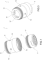
- a safety valve for controlling the dispensing of a fluid according to the invention is indicated as a whole in said drawings by numeral 1.
- the safety valve 1 is combined with an aerator 2 so as to form a single dispensing device 3 of a water flow. As shown in Figure 6 , such a dispensing device 3 of a water flow is connected to the outlet mouth of a tap 4.
- the safety valve 1 can also be used in other circumstances, where an increase in the pressure of the fluid downstream of the safety valve 1 can occur.
- the safety valve 1 comprises a valve body 8 which forms an inlet opening 10 of the fluid, an outlet opening 12 of the fluid, a main passageway 14 for the fluid which fluidly connects the inlet opening 10 to the outlet opening 12.
- the valve body 8 also forms at least one fluid relief opening 16 which fluidly communicates with the outlet opening 12 through a valve seat 18.
- the safety valve 1 comprises a shutter 20 elastically cooperating with the valve seat 18 so as to be normally biased by an elastic means 22 to sealingly close the valve seat 18 and open the valve seat 18 when the pressure of the fluid in the outlet opening 12 exceeds the force applied by the elastic means 22.
- the pressure of the fluid in the outlet opening 12 increases when the outlet opening 12 is in some way throttled or even completely closed, for example by a partially or completely obstructed aerator 2.
- shutter 20 closes the valve seat 18 and therefore the inlet fluid leaves the safety valve 1 through the outlet opening 12.
- shutter 20 opens the valve seat 18 so as to allow the pressurized fluid to be discharged towards the outside through the relief opening 16.
- the pressure of the fluid is then immediately brought below the preset threshold value, avoiding risks of compromising the integrity of the fluid dispensing system.
- a shutter chamber 24 open towards the outlet opening 12 and communicating with the at least one relief opening 16 is obtained in the valve body 8.
- a shutter insert 26 comprising shutter 20 and an annular portion 28 sealingly coupled with the shutter chamber 24 and defining the valve seat 18 cooperating with shutter 20, is accommodated in this shutter chamber 24.
- the shutter chamber 24 is substantially cylindrical in shape, with a chamber opening 24' directly facing the outlet opening 12 of the safety valve 1.
- the annular portion 28 can be toroidal in shape with a "C" cross section open outwards so as to accommodate a sealing element 28', e.g. an O-ring, which cooperates with the wall of the shutter chamber 24 that delimits the chamber opening 24'.
- the shutter insert 26 is inserted into the shutter chamber 24 with a shape and/or force coupling.
- the force coupling can be obtained by the interference between the sealing element 28' and the wall of the shutter chamber 24.
- the shutter chamber 24 is closed at the end opposite to the chamber opening 24' and forms an abutment 30 for the shutter insert 26.
- valve body 8 is formed by an outer tubular portion 80 and by a cartridge portion 100 sealingly accommodated in the outer tubular portion 80.
- the outer tubular portion 80 extends between a first open end 82, which forms the inlet opening 10, a second open end 84, which forms the outlet opening 12.
- the outer tubular portion 80 has a side wall 86 in which the at least one relief opening 16 is obtained.
- the outer tubular portion 80 extends about a body axis X.
- the outer tubular portion 80 is substantially cylindrical in shape.
- the first end 82 can have an outer thread 82, for example for a screwing, with the interposition of an annular sealing gasket 90, to the outlet mouth of the spout of a tap 4; the second end 84 can have an inner thread 84, for example for screwing the aerator 2.
- the shutter chamber 24 and the main passageway 14 are obtained in the cartridge portion 100.
- the cartridge portion 100 comprises a central portion 102 in which there is obtained the shutter chamber 24 and a peripheral portion 104 sealingly coupled with the inner surface of the side wall 86 of the outer tubular portion 80.
- the main passageway 14 is formed by a plurality of channels 14' which cross the peripheral portion 104, for example obtained in uniformly distributed manner about the body axis X. Such channels therefore 14' surround the central portion 100.
- Radial slits 106 which put the valve seat 18 in communication with respective relief openings 16 are obtained in an axially intermediate portion of the peripheral portion 104.
- each radial slit 16 communicates with the shutter chamber 24.
- shutter 20 is axially translatable in the shutter chamber 24 between an advanced closed position of the valve seat 18 ( Figure 5 ) and a retracted open position of the valve seat 18 ( Figure 5a ).
- shutter 20 comprises a shutter portion 202 suitable to sealingly engage the valve seat 18 when shutter 20 is in advanced position, and a guide stem 204 which extends from the shutter portion 202.
- the shutter insert 26 comprises a frame 262, for example made in one piece with the annular element 28, which forms a guide portion 264 which slidingly supports the guide stem 204.
- the elastic means 22 are a helical spring which acts on shutter 20 by compression.
- the helical spring can, for example extend about the guide stem 204 and have an end which acts on the shutter portion 202 and the other end abutting against the frame 262.
- the object of the invention is a dispensing device 3 for a liquid, in particular water, that uses the above-described safety valve 1 and an aerator 2 of the known type, connected to the outlet opening 12 of the safety valve 1.
- Aerator 2 can conventionally be provided with an externally threaded attachment portion 2' which is screwed to the second end 84 of the outer tubular portion 80.
- annular sealing element 5 which rests for example against the peripheral portion 104 of the cartridge portion 100, can be interposed between aerator 2 and the cartridge portion 100.
- the end of the cartridge portion 100 facing aerator 2 is spaced apart from the aerator itself so as to form a liquid outlet chamber 6 into which the channels 14' lead and towards which the valve seat 18 faces.
- the liquid collected in this outlet chamber 6 can reach a pressure level such as to induce the translation of shutter 20 into retracted open position of the valve seat 20 ( Figure 5a ). Thereby, the outlet chamber 6 is put into fluid communication with the radial slits 106 and therefore, with the relief openings 16.
- the increase in pressure downstream of the outlet opening 12 can also be induced in voluntary manner by plugging the outlet opening 12, for example also manually, to force the fluid flow to pass through the relief openings 16 rather than through the outlet opening 12.
Landscapes
- Engineering & Computer Science (AREA)
- General Engineering & Computer Science (AREA)
- Mechanical Engineering (AREA)
- Health & Medical Sciences (AREA)
- Life Sciences & Earth Sciences (AREA)
- Hydrology & Water Resources (AREA)
- Public Health (AREA)
- Water Supply & Treatment (AREA)
- Safety Valves (AREA)
- Devices For Dispensing Beverages (AREA)
- Feeding And Controlling Fuel (AREA)
- Containers And Packaging Bodies Having A Special Means To Remove Contents (AREA)
- Domestic Plumbing Installations (AREA)
Claims (8)
- Hahn (4), umfassend eine Auslassöffnung für die Flüssigkeit bzw. das Fluid, wobei mit der Auslassöffnung eine Abgabevorrichtung (3) für einen Flüssigkeits- bzw. Fluidstrom verbunden ist, umfassend:
ein Sicherheitsventil (1) zum Steuern bzw. Regeln der Abgabe des Flüssigkeitsstroms aus der Auslassöffnung, umfassend:- einen Ventilkörper (8), der eine Einlassöffnung (10) für die Flüssigkeit, eine Auslassöffnung (12) für die Flüssigkeit, einen Hauptdurchgang (14) für die Flüssigkeit, der die Einlassöffnung (10) fluidisch bzw. flüssigkeitsmäßig mit der Auslassöffnung (12) verbindet, zumindest eine Flüssigkeitsentlastungsöffnung (16), die durch einen Ventilsitz (18) fluidisch bzw. flüssigkeitsmäßig mit der Auslassöffnung (12) kommuniziert bzw. in Verbindung ist, bildet;- einen Verschluss (20), der elastisch mit dem Ventilsitz (18) zusammenwirkt, so dass er normal durch ein elastisches Mittel (22) vorgespannt ist, um den Ventilsitz (18) dichtend abzuschließen und den Sitz (18) zu öffnen, wenn der Druck der Flüssigkeit in der Auslassöffnung (12) die durch das elastische Mittel (22) ausgeübte Kraft übersteigt;- einen Belüfter bzw. Strahlregler (2), der mit der Auslassöffnung (12) des Sicherheitsventils (1) verbunden ist. - Hahn nach Anspruch 1, wobei eine Verschlusskammer (24), die zu der Auslassöffnung (12) hin offen ist und mit der zumindest einen Entlastungsöffnung (16) in Verbindung ist, in dem Ventilkörper (8) enthalten bzw. ausgebildet ist, wobei ein Verschlusseinsatz (26), der den Verschluss (20) und einen ringförmigen Abschnitt (28) umfasst, der dichtend mit der Verschlusskammer (24) gekoppelt ist und den Ventilsitz (18) für den Verschluss (20) definiert, in der Verschlusskammer (24) untergebracht ist.
- Hahn nach Anspruch 1 oder 2, wobei der Ventilkörper (8) umfasst:- einen äußeren rohrförmigen Abschnitt (80) mit einem ersten offenen Ende (82), das die Einlassöffnung (10) bildet, einem zweiten offenen Ende (84), das die Auslassöffnung (12) bildet, und einer Seitenwand (86), in der die zumindest eine Entlastungsöffnung (16) ausgebildet ist;- einen Patronenabschnitt (100), der in dem äußeren rohrförmigen Abschnitt (80) untergebracht ist, wobei die Verschlusskammer (24) und der Hauptdurchgang (14) in dem Patronenabschnitt (100) enthalten bzw. ausgebildet sind.
- Hahn nach Anspruch 2 oder 3, wobei der Verschluss (20) in der Verschlusskammer (24) zwischen einer vorgeschobenen geschlossenen Position des Ventilsitzes (18) und einer zurückgezogenen offenen Position des Ventilsitzes (18) beweglich ist.
- Hahn nach dem vorhergehenden Anspruch, wobei der Verschluss (20) einen Verschlussabschnitt (202), der geeignet ist, dichtend in den Ventilsitz (18) einzugreifen, wenn sich der Verschluss (20) in der vorgeschobenen Position befindet, und einen Führungsschaft (204) umfasst, der sich von dem Verschlussabschnitt (202) erstreckt.
- Hahn nach dem vorhergehenden Anspruch, wobei der Verschlusseinsatz (26) einen Führungsabschnitt (264) umfasst, der den Führungsschaft (204) gleitend stützt bzw. trägt.
- Hahn nach einem der vorhergehenden Ansprüche, wobei das elastische Mittel (22) eine Schraubenfeder ist, die durch Kompression auf den Verschluss (20) wirkt.
- Hahn nach einem der Ansprüche 3 bis 7, wobei der Patronenabschnitt (100) einen zentralen Abschnitt (102), in dem die Verschlusskammer (24) enthalten bzw. ausgebildet ist, und einen Umfangsabschnitt (104) umfasst, der dichtend mit der Seitenwand (86) des äußeren rohrförmigen Abschnitts (80) gekoppelt ist, wobei der Hauptdurchgang (14) durch eine Mehrzahl von Kanälen (14') gebildet ist, die den Umfangsabschnitt (104) kreuzen, wobei radiale Schlitze (106), die den Ventilsitz (18) mit jeweiligen Entlastungsöffnungen (16) in Kommunikation bzw. Verbindung bringen, in einem axial mittleren Abschnitt des Umfangsabschnitt (104) enthalten bzw. ausgebildet sind.
Applications Claiming Priority (1)
| Application Number | Priority Date | Filing Date | Title |
|---|---|---|---|
| IT102020000019291A IT202000019291A1 (it) | 2020-08-05 | 2020-08-05 | Dispositivo di erogazione di un fluido con valvola di sicurezza |
Publications (2)
| Publication Number | Publication Date |
|---|---|
| EP3951224A1 EP3951224A1 (de) | 2022-02-09 |
| EP3951224B1 true EP3951224B1 (de) | 2024-07-31 |
Family
ID=72886009
Family Applications (1)
| Application Number | Title | Priority Date | Filing Date |
|---|---|---|---|
| EP21189196.5A Active EP3951224B1 (de) | 2020-08-05 | 2021-08-02 | Flüssigkeitsabgabevorrichtung mit sicherheitsventil |
Country Status (5)
| Country | Link |
|---|---|
| US (1) | US11668405B2 (de) |
| EP (1) | EP3951224B1 (de) |
| JP (1) | JP2022031230A (de) |
| IT (1) | IT202000019291A1 (de) |
| MX (1) | MX2021009387A (de) |
Citations (2)
| Publication number | Priority date | Publication date | Assignee | Title |
|---|---|---|---|---|
| US3884418A (en) * | 1974-08-30 | 1975-05-20 | Cranda Corp | Aerating and spraying attachment for faucets |
| DE102018200530A1 (de) * | 2018-01-15 | 2019-07-18 | Hansgrohe Se | Fluidleitungseinsatz |
Family Cites Families (9)
| Publication number | Priority date | Publication date | Assignee | Title |
|---|---|---|---|---|
| FR2576939B1 (fr) * | 1985-02-01 | 1987-02-13 | Presto Robinets Sa | Dispositif de fixation d'un brise-jet aerateur dans le bec d'un robinet |
| JPS6369779U (de) * | 1986-10-27 | 1988-05-11 | ||
| DE3722665A1 (de) * | 1987-07-09 | 1989-01-26 | Wildfang Dieter Kg | Rueckflussverhinderer |
| DE10259884B4 (de) * | 2002-12-20 | 2008-05-08 | Joma-Polytec Kunststofftechnik Gmbh | Ölfilteranordnung |
| CN102671791B (zh) * | 2012-05-10 | 2014-12-10 | 厦门松霖科技有限公司 | 防爆球头 |
| WO2013166809A1 (zh) * | 2012-05-10 | 2013-11-14 | 厦门松霖科技有限公司 | 防爆球头 |
| US10801632B2 (en) * | 2014-05-08 | 2020-10-13 | Amg Container Controls, Inc. | Two-way valve with rapid decompression flow dynamics |
| CN104971834A (zh) * | 2015-06-30 | 2015-10-14 | 开平市汉顺洁具实业有限公司 | 一种防爆花洒 |
| DE202016006536U1 (de) * | 2016-10-24 | 2018-01-25 | Neoperl Gmbh | Einsetzteil mit einem wasserführenden Patronengehäuse |
-
2020
- 2020-08-05 IT IT102020000019291A patent/IT202000019291A1/it unknown
-
2021
- 2021-08-02 EP EP21189196.5A patent/EP3951224B1/de active Active
- 2021-08-04 US US17/394,139 patent/US11668405B2/en active Active
- 2021-08-04 MX MX2021009387A patent/MX2021009387A/es unknown
- 2021-08-05 JP JP2021128906A patent/JP2022031230A/ja active Pending
Patent Citations (2)
| Publication number | Priority date | Publication date | Assignee | Title |
|---|---|---|---|---|
| US3884418A (en) * | 1974-08-30 | 1975-05-20 | Cranda Corp | Aerating and spraying attachment for faucets |
| DE102018200530A1 (de) * | 2018-01-15 | 2019-07-18 | Hansgrohe Se | Fluidleitungseinsatz |
Also Published As
| Publication number | Publication date |
|---|---|
| US20220042612A1 (en) | 2022-02-10 |
| MX2021009387A (es) | 2022-05-26 |
| IT202000019291A1 (it) | 2022-02-05 |
| JP2022031230A (ja) | 2022-02-18 |
| US11668405B2 (en) | 2023-06-06 |
| EP3951224A1 (de) | 2022-02-09 |
Similar Documents
| Publication | Publication Date | Title |
|---|---|---|
| EP1627169B1 (de) | Überströmabsperrorgan | |
| US5462081A (en) | Excess flow valve | |
| CN103968117B (zh) | 流体调节器及通过调节器加压流体管道的方法 | |
| EP2898386B1 (de) | Ausgeglichener regler mit einer einlassdruckmesssonde | |
| US10296019B2 (en) | Pressure relief vavle | |
| EP1229417A2 (de) | Thermostatventil zum Gebrauch in Notfalldusch- und Augenspülsystemen | |
| WO1998008012A1 (en) | Outlet pressure limiting valve | |
| US4265271A (en) | Relief valve | |
| US11668405B2 (en) | Fluid dispensing device with safety valve | |
| GB2246840A (en) | Safety relief valve | |
| CN106979366B (zh) | 具有定向升压传感管的平衡调节器 | |
| EP1813846A2 (de) | Sicherheitsventil für Fluide | |
| WO1994001706A1 (en) | Valve assembly with backflow prevention and atmospheric vacuum breaker devices | |
| WO2017035172A1 (en) | Back pressure control regulator with in-line overpressure relief | |
| EP4182767B1 (de) | Membrandruckminderer | |
| CH717718A2 (it) | Dispositivo di erogazione di un fluido con valvola di sicurezza. | |
| EP0777074B1 (de) | Verbesserungen an Druckentlastungsventilen | |
| AU2018220117B2 (en) | Fluid Flow Control Device | |
| EP1005670B1 (de) | Druckkompensiertes durchflussventil | |
| CZ279221B6 (cs) | Pojistný ventil přímočinný | |
| EP1008789A2 (de) | Doppelsicherheitsventil zur Druckentlastung mit Schliesshysteresis | |
| US20040231721A1 (en) | Spill-resistant relief valve | |
| AU4547793A (en) | Valve assembly with backflow prevention and atmospheric vacuum breaker devices | |
| AU2005203084A1 (en) | Improved Valve | |
| AU3763497A (en) | Outlet pressure limiting valve |
Legal Events
| Date | Code | Title | Description |
|---|---|---|---|
| PUAI | Public reference made under article 153(3) epc to a published international application that has entered the european phase |
Free format text: ORIGINAL CODE: 0009012 |
|
| STAA | Information on the status of an ep patent application or granted ep patent |
Free format text: STATUS: THE APPLICATION HAS BEEN PUBLISHED |
|
| AK | Designated contracting states |
Kind code of ref document: A1 Designated state(s): AL AT BE BG CH CY CZ DE DK EE ES FI FR GB GR HR HU IE IS IT LI LT LU LV MC MK MT NL NO PL PT RO RS SE SI SK SM TR |
|
| STAA | Information on the status of an ep patent application or granted ep patent |
Free format text: STATUS: REQUEST FOR EXAMINATION WAS MADE |
|
| 17P | Request for examination filed |
Effective date: 20220802 |
|
| RBV | Designated contracting states (corrected) |
Designated state(s): AL AT BE BG CH CY CZ DE DK EE ES FI FR GB GR HR HU IE IS IT LI LT LU LV MC MK MT NL NO PL PT RO RS SE SI SK SM TR |
|
| GRAP | Despatch of communication of intention to grant a patent |
Free format text: ORIGINAL CODE: EPIDOSNIGR1 |
|
| STAA | Information on the status of an ep patent application or granted ep patent |
Free format text: STATUS: GRANT OF PATENT IS INTENDED |
|
| INTG | Intention to grant announced |
Effective date: 20240328 |
|
| GRAS | Grant fee paid |
Free format text: ORIGINAL CODE: EPIDOSNIGR3 |
|
| GRAA | (expected) grant |
Free format text: ORIGINAL CODE: 0009210 |
|
| STAA | Information on the status of an ep patent application or granted ep patent |
Free format text: STATUS: THE PATENT HAS BEEN GRANTED |
|
| AK | Designated contracting states |
Kind code of ref document: B1 Designated state(s): AL AT BE BG CH CY CZ DE DK EE ES FI FR GB GR HR HU IE IS IT LI LT LU LV MC MK MT NL NO PL PT RO RS SE SI SK SM TR |
|
| REG | Reference to a national code |
Ref country code: CH Ref legal event code: EP Ref country code: GB Ref legal event code: FG4D |
|
| REG | Reference to a national code |
Ref country code: DE Ref legal event code: R096 Ref document number: 602021016376 Country of ref document: DE |
|
| REG | Reference to a national code |
Ref country code: IE Ref legal event code: FG4D |
|
| REG | Reference to a national code |
Ref country code: LT Ref legal event code: MG9D |
|
| REG | Reference to a national code |
Ref country code: NL Ref legal event code: MP Effective date: 20240731 |
|
| PG25 | Lapsed in a contracting state [announced via postgrant information from national office to epo] |
Ref country code: PT Free format text: LAPSE BECAUSE OF FAILURE TO SUBMIT A TRANSLATION OF THE DESCRIPTION OR TO PAY THE FEE WITHIN THE PRESCRIBED TIME-LIMIT Effective date: 20241202 |
|
| REG | Reference to a national code |
Ref country code: AT Ref legal event code: MK05 Ref document number: 1708730 Country of ref document: AT Kind code of ref document: T Effective date: 20240731 |
|
| PG25 | Lapsed in a contracting state [announced via postgrant information from national office to epo] |
Ref country code: PT Free format text: LAPSE BECAUSE OF FAILURE TO SUBMIT A TRANSLATION OF THE DESCRIPTION OR TO PAY THE FEE WITHIN THE PRESCRIBED TIME-LIMIT Effective date: 20241202 |
|
| PG25 | Lapsed in a contracting state [announced via postgrant information from national office to epo] |
Ref country code: NO Free format text: LAPSE BECAUSE OF FAILURE TO SUBMIT A TRANSLATION OF THE DESCRIPTION OR TO PAY THE FEE WITHIN THE PRESCRIBED TIME-LIMIT Effective date: 20241031 |
|
| PG25 | Lapsed in a contracting state [announced via postgrant information from national office to epo] |
Ref country code: NL Free format text: LAPSE BECAUSE OF FAILURE TO SUBMIT A TRANSLATION OF THE DESCRIPTION OR TO PAY THE FEE WITHIN THE PRESCRIBED TIME-LIMIT Effective date: 20240731 Ref country code: GR Free format text: LAPSE BECAUSE OF FAILURE TO SUBMIT A TRANSLATION OF THE DESCRIPTION OR TO PAY THE FEE WITHIN THE PRESCRIBED TIME-LIMIT Effective date: 20241101 Ref country code: PL Free format text: LAPSE BECAUSE OF FAILURE TO SUBMIT A TRANSLATION OF THE DESCRIPTION OR TO PAY THE FEE WITHIN THE PRESCRIBED TIME-LIMIT Effective date: 20240731 Ref country code: FI Free format text: LAPSE BECAUSE OF FAILURE TO SUBMIT A TRANSLATION OF THE DESCRIPTION OR TO PAY THE FEE WITHIN THE PRESCRIBED TIME-LIMIT Effective date: 20240731 |
|
| PG25 | Lapsed in a contracting state [announced via postgrant information from national office to epo] |
Ref country code: BG Free format text: LAPSE BECAUSE OF FAILURE TO SUBMIT A TRANSLATION OF THE DESCRIPTION OR TO PAY THE FEE WITHIN THE PRESCRIBED TIME-LIMIT Effective date: 20240731 |
|
| PG25 | Lapsed in a contracting state [announced via postgrant information from national office to epo] |
Ref country code: LV Free format text: LAPSE BECAUSE OF FAILURE TO SUBMIT A TRANSLATION OF THE DESCRIPTION OR TO PAY THE FEE WITHIN THE PRESCRIBED TIME-LIMIT Effective date: 20240731 |
|
| PG25 | Lapsed in a contracting state [announced via postgrant information from national office to epo] |
Ref country code: AT Free format text: LAPSE BECAUSE OF FAILURE TO SUBMIT A TRANSLATION OF THE DESCRIPTION OR TO PAY THE FEE WITHIN THE PRESCRIBED TIME-LIMIT Effective date: 20240731 Ref country code: IS Free format text: LAPSE BECAUSE OF FAILURE TO SUBMIT A TRANSLATION OF THE DESCRIPTION OR TO PAY THE FEE WITHIN THE PRESCRIBED TIME-LIMIT Effective date: 20241130 |
|
| PG25 | Lapsed in a contracting state [announced via postgrant information from national office to epo] |
Ref country code: HR Free format text: LAPSE BECAUSE OF FAILURE TO SUBMIT A TRANSLATION OF THE DESCRIPTION OR TO PAY THE FEE WITHIN THE PRESCRIBED TIME-LIMIT Effective date: 20240731 |
|
| PG25 | Lapsed in a contracting state [announced via postgrant information from national office to epo] |
Ref country code: RS Free format text: LAPSE BECAUSE OF FAILURE TO SUBMIT A TRANSLATION OF THE DESCRIPTION OR TO PAY THE FEE WITHIN THE PRESCRIBED TIME-LIMIT Effective date: 20241031 Ref country code: ES Free format text: LAPSE BECAUSE OF FAILURE TO SUBMIT A TRANSLATION OF THE DESCRIPTION OR TO PAY THE FEE WITHIN THE PRESCRIBED TIME-LIMIT Effective date: 20240731 |
|
| PG25 | Lapsed in a contracting state [announced via postgrant information from national office to epo] |
Ref country code: RS Free format text: LAPSE BECAUSE OF FAILURE TO SUBMIT A TRANSLATION OF THE DESCRIPTION OR TO PAY THE FEE WITHIN THE PRESCRIBED TIME-LIMIT Effective date: 20241031 Ref country code: PL Free format text: LAPSE BECAUSE OF FAILURE TO SUBMIT A TRANSLATION OF THE DESCRIPTION OR TO PAY THE FEE WITHIN THE PRESCRIBED TIME-LIMIT Effective date: 20240731 Ref country code: NO Free format text: LAPSE BECAUSE OF FAILURE TO SUBMIT A TRANSLATION OF THE DESCRIPTION OR TO PAY THE FEE WITHIN THE PRESCRIBED TIME-LIMIT Effective date: 20241031 Ref country code: NL Free format text: LAPSE BECAUSE OF FAILURE TO SUBMIT A TRANSLATION OF THE DESCRIPTION OR TO PAY THE FEE WITHIN THE PRESCRIBED TIME-LIMIT Effective date: 20240731 Ref country code: LV Free format text: LAPSE BECAUSE OF FAILURE TO SUBMIT A TRANSLATION OF THE DESCRIPTION OR TO PAY THE FEE WITHIN THE PRESCRIBED TIME-LIMIT Effective date: 20240731 Ref country code: IS Free format text: LAPSE BECAUSE OF FAILURE TO SUBMIT A TRANSLATION OF THE DESCRIPTION OR TO PAY THE FEE WITHIN THE PRESCRIBED TIME-LIMIT Effective date: 20241130 Ref country code: HR Free format text: LAPSE BECAUSE OF FAILURE TO SUBMIT A TRANSLATION OF THE DESCRIPTION OR TO PAY THE FEE WITHIN THE PRESCRIBED TIME-LIMIT Effective date: 20240731 Ref country code: GR Free format text: LAPSE BECAUSE OF FAILURE TO SUBMIT A TRANSLATION OF THE DESCRIPTION OR TO PAY THE FEE WITHIN THE PRESCRIBED TIME-LIMIT Effective date: 20241101 Ref country code: FI Free format text: LAPSE BECAUSE OF FAILURE TO SUBMIT A TRANSLATION OF THE DESCRIPTION OR TO PAY THE FEE WITHIN THE PRESCRIBED TIME-LIMIT Effective date: 20240731 Ref country code: ES Free format text: LAPSE BECAUSE OF FAILURE TO SUBMIT A TRANSLATION OF THE DESCRIPTION OR TO PAY THE FEE WITHIN THE PRESCRIBED TIME-LIMIT Effective date: 20240731 Ref country code: BG Free format text: LAPSE BECAUSE OF FAILURE TO SUBMIT A TRANSLATION OF THE DESCRIPTION OR TO PAY THE FEE WITHIN THE PRESCRIBED TIME-LIMIT Effective date: 20240731 Ref country code: AT Free format text: LAPSE BECAUSE OF FAILURE TO SUBMIT A TRANSLATION OF THE DESCRIPTION OR TO PAY THE FEE WITHIN THE PRESCRIBED TIME-LIMIT Effective date: 20240731 |
|
| REG | Reference to a national code |
Ref country code: CH Ref legal event code: PL |
|
| PG25 | Lapsed in a contracting state [announced via postgrant information from national office to epo] |
Ref country code: DK Free format text: LAPSE BECAUSE OF FAILURE TO SUBMIT A TRANSLATION OF THE DESCRIPTION OR TO PAY THE FEE WITHIN THE PRESCRIBED TIME-LIMIT Effective date: 20240731 Ref country code: RO Free format text: LAPSE BECAUSE OF FAILURE TO SUBMIT A TRANSLATION OF THE DESCRIPTION OR TO PAY THE FEE WITHIN THE PRESCRIBED TIME-LIMIT Effective date: 20240731 Ref country code: SM Free format text: LAPSE BECAUSE OF FAILURE TO SUBMIT A TRANSLATION OF THE DESCRIPTION OR TO PAY THE FEE WITHIN THE PRESCRIBED TIME-LIMIT Effective date: 20240731 |
|
| PG25 | Lapsed in a contracting state [announced via postgrant information from national office to epo] |
Ref country code: LU Free format text: LAPSE BECAUSE OF NON-PAYMENT OF DUE FEES Effective date: 20240802 |
|
| PG25 | Lapsed in a contracting state [announced via postgrant information from national office to epo] |
Ref country code: MC Free format text: LAPSE BECAUSE OF FAILURE TO SUBMIT A TRANSLATION OF THE DESCRIPTION OR TO PAY THE FEE WITHIN THE PRESCRIBED TIME-LIMIT Effective date: 20240731 Ref country code: CH Free format text: LAPSE BECAUSE OF NON-PAYMENT OF DUE FEES Effective date: 20240831 Ref country code: EE Free format text: LAPSE BECAUSE OF FAILURE TO SUBMIT A TRANSLATION OF THE DESCRIPTION OR TO PAY THE FEE WITHIN THE PRESCRIBED TIME-LIMIT Effective date: 20240731 |
|
| PG25 | Lapsed in a contracting state [announced via postgrant information from national office to epo] |
Ref country code: CZ Free format text: LAPSE BECAUSE OF FAILURE TO SUBMIT A TRANSLATION OF THE DESCRIPTION OR TO PAY THE FEE WITHIN THE PRESCRIBED TIME-LIMIT Effective date: 20240731 |
|
| PG25 | Lapsed in a contracting state [announced via postgrant information from national office to epo] |
Ref country code: SK Free format text: LAPSE BECAUSE OF FAILURE TO SUBMIT A TRANSLATION OF THE DESCRIPTION OR TO PAY THE FEE WITHIN THE PRESCRIBED TIME-LIMIT Effective date: 20240731 Ref country code: IT Free format text: LAPSE BECAUSE OF FAILURE TO SUBMIT A TRANSLATION OF THE DESCRIPTION OR TO PAY THE FEE WITHIN THE PRESCRIBED TIME-LIMIT Effective date: 20240731 |
|
| REG | Reference to a national code |
Ref country code: DE Ref legal event code: R097 Ref document number: 602021016376 Country of ref document: DE |
|
| PLBE | No opposition filed within time limit |
Free format text: ORIGINAL CODE: 0009261 |
|
| STAA | Information on the status of an ep patent application or granted ep patent |
Free format text: STATUS: NO OPPOSITION FILED WITHIN TIME LIMIT |
|
| REG | Reference to a national code |
Ref country code: BE Ref legal event code: MM Effective date: 20240831 |
|
| 26N | No opposition filed |
Effective date: 20250501 |
|
| PG25 | Lapsed in a contracting state [announced via postgrant information from national office to epo] |
Ref country code: BE Free format text: LAPSE BECAUSE OF NON-PAYMENT OF DUE FEES Effective date: 20240831 |
|
| PG25 | Lapsed in a contracting state [announced via postgrant information from national office to epo] |
Ref country code: FR Free format text: LAPSE BECAUSE OF NON-PAYMENT OF DUE FEES Effective date: 20240930 |
|
| PG25 | Lapsed in a contracting state [announced via postgrant information from national office to epo] |
Ref country code: IE Free format text: LAPSE BECAUSE OF NON-PAYMENT OF DUE FEES Effective date: 20240802 |
|
| PG25 | Lapsed in a contracting state [announced via postgrant information from national office to epo] |
Ref country code: SE Free format text: LAPSE BECAUSE OF FAILURE TO SUBMIT A TRANSLATION OF THE DESCRIPTION OR TO PAY THE FEE WITHIN THE PRESCRIBED TIME-LIMIT Effective date: 20240731 |
|
| PG25 | Lapsed in a contracting state [announced via postgrant information from national office to epo] |
Ref country code: CY Free format text: LAPSE BECAUSE OF FAILURE TO SUBMIT A TRANSLATION OF THE DESCRIPTION OR TO PAY THE FEE WITHIN THE PRESCRIBED TIME-LIMIT; INVALID AB INITIO Effective date: 20210802 |
|
| PG25 | Lapsed in a contracting state [announced via postgrant information from national office to epo] |
Ref country code: HU Free format text: LAPSE BECAUSE OF FAILURE TO SUBMIT A TRANSLATION OF THE DESCRIPTION OR TO PAY THE FEE WITHIN THE PRESCRIBED TIME-LIMIT; INVALID AB INITIO Effective date: 20210802 |
|
| PGFP | Annual fee paid to national office [announced via postgrant information from national office to epo] |
Ref country code: DE Payment date: 20260203 Year of fee payment: 5 |
|
| GBPC | Gb: european patent ceased through non-payment of renewal fee |
Effective date: 20250802 |