EP3951230A2 - Système de connexion pour système distributer de l'eau - Google Patents
Système de connexion pour système distributer de l'eau Download PDFInfo
- Publication number
- EP3951230A2 EP3951230A2 EP21189167.6A EP21189167A EP3951230A2 EP 3951230 A2 EP3951230 A2 EP 3951230A2 EP 21189167 A EP21189167 A EP 21189167A EP 3951230 A2 EP3951230 A2 EP 3951230A2
- Authority
- EP
- European Patent Office
- Prior art keywords
- pipe
- connection system
- end portion
- connection
- insert
- Prior art date
- Legal status (The legal status is an assumption and is not a legal conclusion. Google has not performed a legal analysis and makes no representation as to the accuracy of the status listed.)
- Pending
Links
Images



Classifications
-
- F—MECHANICAL ENGINEERING; LIGHTING; HEATING; WEAPONS; BLASTING
- F16—ENGINEERING ELEMENTS AND UNITS; GENERAL MEASURES FOR PRODUCING AND MAINTAINING EFFECTIVE FUNCTIONING OF MACHINES OR INSTALLATIONS; THERMAL INSULATION IN GENERAL
- F16L—PIPES; JOINTS OR FITTINGS FOR PIPES; SUPPORTS FOR PIPES, CABLES OR PROTECTIVE TUBING; MEANS FOR THERMAL INSULATION IN GENERAL
- F16L33/00—Arrangements for connecting hoses to rigid members; Rigid hose-connectors, i.e. single members engaging both hoses
- F16L33/20—Undivided rings, sleeves, or like members contracted on the hose or expanded inside the hose by means of tools; Arrangements using such members
- F16L33/207—Undivided rings, sleeves, or like members contracted on the hose or expanded inside the hose by means of tools; Arrangements using such members only a sleeve being contracted on the hose
- F16L33/2071—Undivided rings, sleeves, or like members contracted on the hose or expanded inside the hose by means of tools; Arrangements using such members only a sleeve being contracted on the hose the sleeve being a separate connecting member
- F16L33/2078—Undivided rings, sleeves, or like members contracted on the hose or expanded inside the hose by means of tools; Arrangements using such members only a sleeve being contracted on the hose the sleeve being a separate connecting member connected to the rigid member via an intermediate element
-
- F—MECHANICAL ENGINEERING; LIGHTING; HEATING; WEAPONS; BLASTING
- F16—ENGINEERING ELEMENTS AND UNITS; GENERAL MEASURES FOR PRODUCING AND MAINTAINING EFFECTIVE FUNCTIONING OF MACHINES OR INSTALLATIONS; THERMAL INSULATION IN GENERAL
- F16L—PIPES; JOINTS OR FITTINGS FOR PIPES; SUPPORTS FOR PIPES, CABLES OR PROTECTIVE TUBING; MEANS FOR THERMAL INSULATION IN GENERAL
- F16L27/00—Adjustable joints; Joints allowing movement
- F16L27/10—Adjustable joints; Joints allowing movement comprising a flexible connection only
- F16L27/107—Adjustable joints; Joints allowing movement comprising a flexible connection only the ends of the pipe being interconnected by a flexible sleeve
-
- F—MECHANICAL ENGINEERING; LIGHTING; HEATING; WEAPONS; BLASTING
- F16—ENGINEERING ELEMENTS AND UNITS; GENERAL MEASURES FOR PRODUCING AND MAINTAINING EFFECTIVE FUNCTIONING OF MACHINES OR INSTALLATIONS; THERMAL INSULATION IN GENERAL
- F16L—PIPES; JOINTS OR FITTINGS FOR PIPES; SUPPORTS FOR PIPES, CABLES OR PROTECTIVE TUBING; MEANS FOR THERMAL INSULATION IN GENERAL
- F16L11/00—Hoses, i.e. flexible pipes
- F16L11/04—Hoses, i.e. flexible pipes made of rubber or flexible plastics
- F16L11/08—Hoses, i.e. flexible pipes made of rubber or flexible plastics with reinforcements embedded in the wall
-
- F—MECHANICAL ENGINEERING; LIGHTING; HEATING; WEAPONS; BLASTING
- F16—ENGINEERING ELEMENTS AND UNITS; GENERAL MEASURES FOR PRODUCING AND MAINTAINING EFFECTIVE FUNCTIONING OF MACHINES OR INSTALLATIONS; THERMAL INSULATION IN GENERAL
- F16L—PIPES; JOINTS OR FITTINGS FOR PIPES; SUPPORTS FOR PIPES, CABLES OR PROTECTIVE TUBING; MEANS FOR THERMAL INSULATION IN GENERAL
- F16L27/00—Adjustable joints; Joints allowing movement
- F16L27/08—Adjustable joints; Joints allowing movement allowing adjustment or movement only about the axis of one pipe
- F16L27/0804—Adjustable joints; Joints allowing movement allowing adjustment or movement only about the axis of one pipe the fluid passing axially from one joint element to another
- F16L27/0808—Adjustable joints; Joints allowing movement allowing adjustment or movement only about the axis of one pipe the fluid passing axially from one joint element to another the joint elements extending coaxially for some distance from their point of separation
-
- F—MECHANICAL ENGINEERING; LIGHTING; HEATING; WEAPONS; BLASTING
- F16—ENGINEERING ELEMENTS AND UNITS; GENERAL MEASURES FOR PRODUCING AND MAINTAINING EFFECTIVE FUNCTIONING OF MACHINES OR INSTALLATIONS; THERMAL INSULATION IN GENERAL
- F16L—PIPES; JOINTS OR FITTINGS FOR PIPES; SUPPORTS FOR PIPES, CABLES OR PROTECTIVE TUBING; MEANS FOR THERMAL INSULATION IN GENERAL
- F16L27/00—Adjustable joints; Joints allowing movement
- F16L27/08—Adjustable joints; Joints allowing movement allowing adjustment or movement only about the axis of one pipe
- F16L27/0804—Adjustable joints; Joints allowing movement allowing adjustment or movement only about the axis of one pipe the fluid passing axially from one joint element to another
- F16L27/0808—Adjustable joints; Joints allowing movement allowing adjustment or movement only about the axis of one pipe the fluid passing axially from one joint element to another the joint elements extending coaxially for some distance from their point of separation
- F16L27/0812—Adjustable joints; Joints allowing movement allowing adjustment or movement only about the axis of one pipe the fluid passing axially from one joint element to another the joint elements extending coaxially for some distance from their point of separation with slide bearings
- F16L27/0816—Adjustable joints; Joints allowing movement allowing adjustment or movement only about the axis of one pipe the fluid passing axially from one joint element to another the joint elements extending coaxially for some distance from their point of separation with slide bearings having radial sealing
-
- F—MECHANICAL ENGINEERING; LIGHTING; HEATING; WEAPONS; BLASTING
- F16—ENGINEERING ELEMENTS AND UNITS; GENERAL MEASURES FOR PRODUCING AND MAINTAINING EFFECTIVE FUNCTIONING OF MACHINES OR INSTALLATIONS; THERMAL INSULATION IN GENERAL
- F16L—PIPES; JOINTS OR FITTINGS FOR PIPES; SUPPORTS FOR PIPES, CABLES OR PROTECTIVE TUBING; MEANS FOR THERMAL INSULATION IN GENERAL
- F16L27/00—Adjustable joints; Joints allowing movement
- F16L27/10—Adjustable joints; Joints allowing movement comprising a flexible connection only
- F16L27/1012—Flanged joints
-
- F—MECHANICAL ENGINEERING; LIGHTING; HEATING; WEAPONS; BLASTING
- F16—ENGINEERING ELEMENTS AND UNITS; GENERAL MEASURES FOR PRODUCING AND MAINTAINING EFFECTIVE FUNCTIONING OF MACHINES OR INSTALLATIONS; THERMAL INSULATION IN GENERAL
- F16L—PIPES; JOINTS OR FITTINGS FOR PIPES; SUPPORTS FOR PIPES, CABLES OR PROTECTIVE TUBING; MEANS FOR THERMAL INSULATION IN GENERAL
- F16L33/00—Arrangements for connecting hoses to rigid members; Rigid hose-connectors, i.e. single members engaging both hoses
- F16L33/22—Arrangements for connecting hoses to rigid members; Rigid hose-connectors, i.e. single members engaging both hoses with means not mentioned in the preceding groups for gripping the hose between inner and outer parts
Definitions
- the present invention relates to a connection system for distributing water in a domestic system.
- the technical field to which the present invention applies is that of domestic plumbing systems.
- plumbing system means the domestic system which allows the distribution and access to water by virtue of a faucet or other hydraulic connector.
- plastic pipes are prone to show dirt due to the local accumulation of water over time, ending up being less hygienic, thus less suitable to contact with drinking water, as well as having a poorer appearance.
- connection system which applies to the aforementioned technical field and having mechanical properties suitable to withstand the forces impressed during the clamping.
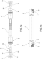
- reference numeral 1 indicates as a whole the connection system according to the present invention.
- connection system 1 comprises a flexible pipe 2 having at least one end portion which is suitable for the connection to a hydraulic connector, not depicted in the figures.
- connection system can connect a showerhead to a wall-mounted hydraulic connector of a shower, or can connect a spout of a faucet of a sink, such as a kitchen sink, for example, to the domestic plumbing system.
- the pipe 2 comprises an inner PVC layer, an outer PVC layer, and an intermediate layer comprising longitudinal twisted fabric fibers and comprising a silver paint.
- said pipe 2 is made of a material complying with the DVGW W270:2007 standard.
- the pipe 2 is made of a material suitable to come into contact with drinking water supplied by a plumbing system, without altering the properties which make the water suitable for human consumption over time.
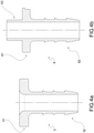
- connection system 1 comprises at least one hollow insert 3; 6 which axially engages at least one of the two opposite end portions of the flexible pipe 2.
- the hollow insert 3; 6 comprises a head portion 31; 61 having a flange-like shape which abuts against the free end of the pipe 2.
- a reinforcement portion 31; 62 extends from the head portion 32; 61, being housed inside the end portion of the pipe 2.
- the insert 3; 6 is preferably made in one piece of a material complying with the DVGW W270:2007 standard.
- the insert 3; 6 is made of a material suitable to come into contact with drinking water supplied by a plumbing system, without altering the properties which make the water suitable for human consumption over time.
- connection system 1 comprises an annular bushing 4 mechanically clamped onto the end portion of the pipe 2 which accommodates the reinforcement portion 32; 62 of the insert 3; 6.
- the annular bushing 4 makes the end portion of the pipe 2 and the hollow insert 3; 6 integral with each other. Thereby, the hollow insert 3; 6 cannot translate axially with respect to the pipe 2.
- the hollow insert 3; 6 comprises one or more annular teeth 35; 65 axially spaced apart from one another along the reinforcement portion 32; 62.
- annular teeth 35; 65 engage the inner wall of the pipe 2, interpenetrating therewith. Furthermore, the orientation of the annular teeth 35; 65 can be chosen so that the thrust applied to the hollow insert by the pressurized water present in the pipe 2 further contributes to making the annular teeth 35; 65 penetrate the wall of the pipe 2.
- connection system 1 comprises at least one connecting element 5, having a truncated cone shape, for example, fitted onto the end portion of the pipe 2 and comprising means for the connection to the hydraulic connector.
- the connecting element 5 allows the actual connection of the connection system to the hydraulic connector of the domestic system.
- connection means are threaded connection means.
- connection means comprise a thread 55 obtained in the inner surface of the side wall of the connecting element 5.
- the insert 6 comprises a hollow pin 63 which extends from the head portion 61 in a direction opposite to the reinforcement portion 62.
- the hollow pin 63 is made in one piece with the hollow insert 6.
- a rotatable annular element 7 is fitted about the hollow pin 63 with rotation possibility, being suitable to decouple the pipe 2 under rotation from the connecting element 5 when the latter is integral with the hydraulic connector.
- the presence of the rotatable annular element 7 allows to vary the angular position of the pipe 2 with respect to the connecting element 5 when using the connection system.
- the rotatable annular element 7 is also made of a material complying with the DVGW W270:2007 standard.
- the rotatable annular element 7 houses a hydraulic sealing element 71, such as an O-ring, for example, which cooperates with the side wall of the hollow pin 63.
- the hydraulic sealing element 71 achieves a hydraulic continuity between the insert 6 and the end portion of the pipe 2 in which it is inserted.
- the connecting element 5 internally forms a seat for the annular element 7.
- the end portion of the pipe 2 comprises a terminal co-molded with the pipe 2.
- the terminal 8 and the pipe 2 are preferably made of a material complying with the DVGW W270:2007 standard.
- a rotating bushing 9 made of a material complying with the DVGW W270:2007 standard, for example, is inserted into the co-molded terminal 8.
- Such a rotating bushing 9 preferably comprises a guiding portion 91 inserted into the co-molded terminal 8 and a flanged head 92 which abuts against the edge of the co-molded terminal 8.
- a non-return valve 11 is inserted into the co-molded terminal 8.
- a flow limiter 10 is inserted into the co-molded terminal 8.
- the connecting element 5 comprises at least one hydraulic seal, such as an O-ring, for example.
- the hollow inserts allow optimal clamping, because the plastics involved do not give yield due to the impressed forces nor are damaged, thus reducing the risk of sudden failure of the pipe.
- the teeth of the hollow inserts after clamping, also locally interpenetrate into the inner wall of the pipe, thus avoiding the risk of axial release of the insert due to internal pressures.
- connection system has an end equipped with elements which are free to rotate reciprocally, which prevent the pipe from winding on itself.
- connection system described in the present invention is also made of a material complying with the DVGW W270:2007 standard, whereby it is particularly suitable to come into contact with drinking water, even for prolonged use over time.
- connection system comprises a pipe made of a plastic material, therefore less expensive, but flexible and durable at the same time.
- the pipe is painted with a durable silver paint which is not attacked by scaling, thus having a better appearance.
Landscapes
- Engineering & Computer Science (AREA)
- General Engineering & Computer Science (AREA)
- Mechanical Engineering (AREA)
- Domestic Plumbing Installations (AREA)
- Quick-Acting Or Multi-Walled Pipe Joints (AREA)
- Joints That Cut Off Fluids, And Hose Joints (AREA)
- Joints Allowing Movement (AREA)
Applications Claiming Priority (1)
| Application Number | Priority Date | Filing Date | Title |
|---|---|---|---|
| IT202000004645 | 2020-08-05 |
Publications (2)
| Publication Number | Publication Date |
|---|---|
| EP3951230A2 true EP3951230A2 (fr) | 2022-02-09 |
| EP3951230A3 EP3951230A3 (fr) | 2022-06-15 |
Family
ID=79554205
Family Applications (1)
| Application Number | Title | Priority Date | Filing Date |
|---|---|---|---|
| EP21189167.6A Pending EP3951230A3 (fr) | 2020-08-05 | 2021-08-02 | Système de connexion pour système distributer de l'eau |
Country Status (4)
| Country | Link |
|---|---|
| US (1) | US11774019B2 (fr) |
| EP (1) | EP3951230A3 (fr) |
| JP (1) | JP2022031231A (fr) |
| MX (1) | MX2021009386A (fr) |
Families Citing this family (2)
| Publication number | Priority date | Publication date | Assignee | Title |
|---|---|---|---|---|
| US12504104B2 (en) * | 2023-09-08 | 2025-12-23 | Guangzhou Fengxue Technology Co., Ltd. | Adapter assembly |
| EP4607073A1 (fr) * | 2024-02-20 | 2025-08-27 | Graco Minnesota Inc. | Raccord rapide pour un système de pulvérisation |
Family Cites Families (18)
| Publication number | Priority date | Publication date | Assignee | Title |
|---|---|---|---|---|
| US2273397A (en) * | 1941-04-05 | 1942-02-17 | Flex O Tube Company | Swivel hose fitting |
| US3999781A (en) * | 1973-05-02 | 1976-12-28 | Todd William H | Universal swivel hose coupling |
| JPS5483B2 (fr) * | 1974-04-02 | 1979-01-06 | ||
| JPS5659093A (en) * | 1979-10-17 | 1981-05-22 | Bridgestone Tire Co Ltd | Calking joint of hose |
| DE9005930U1 (de) * | 1990-05-25 | 1990-08-16 | Ruhnke, Gottfried, 6200 Wiesbaden | Schraubanschluß für einen Duschenschlauch |
| US5160178A (en) * | 1991-12-17 | 1992-11-03 | Kabushiki Kaisha Com | Direct sealing coupling |
| DE4430114C2 (de) * | 1994-07-19 | 1997-12-04 | Friedhelm Ramspott Metall Und | Anschlußstück für einen Kunststoffschlauch einer Badezimmer-Handbrause |
| ATE180553T1 (de) * | 1995-02-21 | 1999-06-15 | Oldoplast Kunststoffprofile Gmbh | Sanitärschlauch mit drehbarer kupplung eines anschlussstückes |
| JP2003524734A (ja) * | 1998-02-09 | 2003-08-19 | リンキンデクス・リミテッド | ホースコネクタ及びホースコネクタのためのネジ付カラー |
| AU2002242794A1 (en) * | 2002-02-28 | 2003-09-09 | Pierre Tournier | Adjustable-flow insert for a tube that is intended for bathroom facilities |
| US7108292B2 (en) * | 2003-04-08 | 2006-09-19 | Fiskars Brands, Inc. | Hose coupler |
| US20080217432A1 (en) * | 2007-03-09 | 2008-09-11 | Chao-Chang Wu | Sealing connection assembly for a handheld showerhead assembly |
| DE102010039541B4 (de) * | 2010-08-19 | 2014-10-02 | Hansgrohe Se | Schlauchanschlussnippel |
| US9303800B2 (en) * | 2010-11-12 | 2016-04-05 | Fluidmaster, Inc. | Torque limiting fluid connector system |
| JP2012122533A (ja) * | 2010-12-07 | 2012-06-28 | Toyox Co Ltd | ホース接続具及びシャワーホース用継手構造 |
| CA2863872C (fr) * | 2013-09-13 | 2019-10-22 | Neal Wood | Raccord hydraulique pour flexible hydraulique |
| JP6048978B2 (ja) * | 2014-12-05 | 2016-12-21 | 株式会社トヨックス | 管継手及びシャワーホース接続構造 |
| US10458574B2 (en) * | 2015-04-24 | 2019-10-29 | Teknor Apex Company | Lightweight, high flow hose assembly and method of manufacture |
-
2021
- 2021-08-02 EP EP21189167.6A patent/EP3951230A3/fr active Pending
- 2021-08-04 US US17/393,842 patent/US11774019B2/en active Active
- 2021-08-04 MX MX2021009386A patent/MX2021009386A/es unknown
- 2021-08-05 JP JP2021128907A patent/JP2022031231A/ja active Pending
Also Published As
| Publication number | Publication date |
|---|---|
| US11774019B2 (en) | 2023-10-03 |
| MX2021009386A (es) | 2022-04-25 |
| EP3951230A3 (fr) | 2022-06-15 |
| US20220042633A1 (en) | 2022-02-10 |
| JP2022031231A (ja) | 2022-02-18 |
Similar Documents
| Publication | Publication Date | Title |
|---|---|---|
| US5419363A (en) | Plumbing adapter | |
| US8985142B2 (en) | Flow quantity regulator | |
| US11774019B2 (en) | Connection system for distributing water | |
| CN112443674B (zh) | 一种龙头出水构件 | |
| KR102304858B1 (ko) | 꼬임방지 기능을 갖는 수도배관용 고압호스 연결구 | |
| CA1270724A (fr) | Robinet sanitaire de coupure ou mitigeur | |
| US8011384B2 (en) | Bridge faucet | |
| US7100637B1 (en) | Wall hydrant having backflow preventor | |
| US11274424B2 (en) | Detachable faucet connector | |
| CN211039728U (zh) | 可调节伸缩式角阀 | |
| US10619334B2 (en) | Tub spout with flexible portion and inflexible portion | |
| US12018466B2 (en) | Tub spout diverter seal member | |
| CN221170882U (zh) | 一种复合型环保浴缸龙头 | |
| CN208764524U (zh) | 一种防缠绕淋浴软管 | |
| CN108105443B (zh) | 可旋转出水管及包括该可旋转出水管的多功能水龙头 | |
| KR200442311Y1 (ko) | 분기용 밸브캡 조립체 | |
| JP2660904B2 (ja) | 節水器具 | |
| AU2008202706B2 (en) | Shower Pivot | |
| CH717717B1 (it) | Sistema di connessione per la distribuzione di acqua. | |
| US11002388B2 (en) | Fire hydrant nozzle | |
| KR20210076578A (ko) | 수전과 급수관 연결용 자유회전 구조를 갖춘 앵글밸브 | |
| US20250198649A1 (en) | Valve assembly for ac condensate line | |
| CN210716085U (zh) | 塑料混水龙头连接件 | |
| KR101912309B1 (ko) | 급수밸브 | |
| AU2011101054A4 (en) | Adaptor fitting |
Legal Events
| Date | Code | Title | Description |
|---|---|---|---|
| PUAI | Public reference made under article 153(3) epc to a published international application that has entered the european phase |
Free format text: ORIGINAL CODE: 0009012 |
|
| STAA | Information on the status of an ep patent application or granted ep patent |
Free format text: STATUS: THE APPLICATION HAS BEEN PUBLISHED |
|
| AK | Designated contracting states |
Kind code of ref document: A2 Designated state(s): AL AT BE BG CH CY CZ DE DK EE ES FI FR GB GR HR HU IE IS IT LI LT LU LV MC MK MT NL NO PL PT RO RS SE SI SK SM TR |
|
| PUAL | Search report despatched |
Free format text: ORIGINAL CODE: 0009013 |
|
| AK | Designated contracting states |
Kind code of ref document: A3 Designated state(s): AL AT BE BG CH CY CZ DE DK EE ES FI FR GB GR HR HU IE IS IT LI LT LU LV MC MK MT NL NO PL PT RO RS SE SI SK SM TR |
|
| RIC1 | Information provided on ipc code assigned before grant |
Ipc: F16L 33/22 20060101ALI20220506BHEP Ipc: F16L 33/207 20060101ALI20220506BHEP Ipc: F16L 27/08 20060101AFI20220506BHEP |
|
| STAA | Information on the status of an ep patent application or granted ep patent |
Free format text: STATUS: REQUEST FOR EXAMINATION WAS MADE |
|
| 17P | Request for examination filed |
Effective date: 20221214 |
|
| RBV | Designated contracting states (corrected) |
Designated state(s): AL AT BE BG CH CY CZ DE DK EE ES FI FR GB GR HR HU IE IS IT LI LT LU LV MC MK MT NL NO PL PT RO RS SE SI SK SM TR |
|
| STAA | Information on the status of an ep patent application or granted ep patent |
Free format text: STATUS: EXAMINATION IS IN PROGRESS |
|
| 17Q | First examination report despatched |
Effective date: 20240403 |