EP3951264B1 - Wärmeaustauschanordnung und wärmeaustauschvorrichtung - Google Patents
Wärmeaustauschanordnung und wärmeaustauschvorrichtung Download PDFInfo
- Publication number
- EP3951264B1 EP3951264B1 EP19921587.2A EP19921587A EP3951264B1 EP 3951264 B1 EP3951264 B1 EP 3951264B1 EP 19921587 A EP19921587 A EP 19921587A EP 3951264 B1 EP3951264 B1 EP 3951264B1
- Authority
- EP
- European Patent Office
- Prior art keywords
- flue gas
- flue
- heat exchange
- dampers
- tube bank
- Prior art date
- Legal status (The legal status is an assumption and is not a legal conclusion. Google has not performed a legal analysis and makes no representation as to the accuracy of the status listed.)
- Active
Links
Images


Classifications
-
- F—MECHANICAL ENGINEERING; LIGHTING; HEATING; WEAPONS; BLASTING
- F23—COMBUSTION APPARATUS; COMBUSTION PROCESSES
- F23J—REMOVAL OR TREATMENT OF COMBUSTION PRODUCTS OR COMBUSTION RESIDUES; FLUES
- F23J11/00—Devices for conducting smoke or fumes, e.g. flues
-
- F—MECHANICAL ENGINEERING; LIGHTING; HEATING; WEAPONS; BLASTING
- F23—COMBUSTION APPARATUS; COMBUSTION PROCESSES
- F23J—REMOVAL OR TREATMENT OF COMBUSTION PRODUCTS OR COMBUSTION RESIDUES; FLUES
- F23J13/00—Fittings for chimneys or flues
- F23J13/02—Linings; Jackets; Casings
-
- F—MECHANICAL ENGINEERING; LIGHTING; HEATING; WEAPONS; BLASTING
- F23—COMBUSTION APPARATUS; COMBUSTION PROCESSES
- F23J—REMOVAL OR TREATMENT OF COMBUSTION PRODUCTS OR COMBUSTION RESIDUES; FLUES
- F23J13/00—Fittings for chimneys or flues
- F23J13/08—Doors or covers specially adapted for smoke-boxes, flues, or chimneys
-
- F—MECHANICAL ENGINEERING; LIGHTING; HEATING; WEAPONS; BLASTING
- F23—COMBUSTION APPARATUS; COMBUSTION PROCESSES
- F23J—REMOVAL OR TREATMENT OF COMBUSTION PRODUCTS OR COMBUSTION RESIDUES; FLUES
- F23J15/00—Arrangements of devices for treating smoke or fumes
- F23J15/06—Arrangements of devices for treating smoke or fumes of coolers
-
- F—MECHANICAL ENGINEERING; LIGHTING; HEATING; WEAPONS; BLASTING
- F23—COMBUSTION APPARATUS; COMBUSTION PROCESSES
- F23J—REMOVAL OR TREATMENT OF COMBUSTION PRODUCTS OR COMBUSTION RESIDUES; FLUES
- F23J2211/00—Flue gas duct systems
-
- F—MECHANICAL ENGINEERING; LIGHTING; HEATING; WEAPONS; BLASTING
- F23—COMBUSTION APPARATUS; COMBUSTION PROCESSES
- F23J—REMOVAL OR TREATMENT OF COMBUSTION PRODUCTS OR COMBUSTION RESIDUES; FLUES
- F23J2213/00—Chimneys or flues
- F23J2213/60—Service arrangements
-
- F—MECHANICAL ENGINEERING; LIGHTING; HEATING; WEAPONS; BLASTING
- F23—COMBUSTION APPARATUS; COMBUSTION PROCESSES
- F23N—REGULATING OR CONTROLLING COMBUSTION
- F23N2235/00—Valves, nozzles or pumps
- F23N2235/02—Air or combustion gas valves or dampers
- F23N2235/04—Air or combustion gas valves or dampers in stacks
-
- F—MECHANICAL ENGINEERING; LIGHTING; HEATING; WEAPONS; BLASTING
- F23—COMBUSTION APPARATUS; COMBUSTION PROCESSES
- F23N—REGULATING OR CONTROLLING COMBUSTION
- F23N2235/00—Valves, nozzles or pumps
- F23N2235/02—Air or combustion gas valves or dampers
- F23N2235/08—Air or combustion gas valves or dampers used with heat exchanges
-
- F—MECHANICAL ENGINEERING; LIGHTING; HEATING; WEAPONS; BLASTING
- F23—COMBUSTION APPARATUS; COMBUSTION PROCESSES
- F23N—REGULATING OR CONTROLLING COMBUSTION
- F23N2235/00—Valves, nozzles or pumps
- F23N2235/02—Air or combustion gas valves or dampers
- F23N2235/10—Air or combustion gas valves or dampers power assisted, e.g. using electric motors
-
- Y—GENERAL TAGGING OF NEW TECHNOLOGICAL DEVELOPMENTS; GENERAL TAGGING OF CROSS-SECTIONAL TECHNOLOGIES SPANNING OVER SEVERAL SECTIONS OF THE IPC; TECHNICAL SUBJECTS COVERED BY FORMER USPC CROSS-REFERENCE ART COLLECTIONS [XRACs] AND DIGESTS
- Y02—TECHNOLOGIES OR APPLICATIONS FOR MITIGATION OR ADAPTATION AGAINST CLIMATE CHANGE
- Y02E—REDUCTION OF GREENHOUSE GAS [GHG] EMISSIONS, RELATED TO ENERGY GENERATION, TRANSMISSION OR DISTRIBUTION
- Y02E20/00—Combustion technologies with mitigation potential
- Y02E20/30—Technologies for a more efficient combustion or heat usage
Definitions
- the present invention relates to a heat exchange flue and a heat exchange device such as a boiler including the heat exchange flue.
- DE 621876C provides a soot cleaning device for flue gas preheaters, the flue gas itself or low-pressure air is driven at high speed perpendicular to the operating gas flow path between the tubes by means of flaps arranged at the inlet and outlet of the tube bundle, thereby agitating and entraining the soot deposits located in the flow shadow.
- US 2716021A provides a method and apparatus for cleaning tube banks. This invention relates to tubular fluid heat exchangers and to a novel method of and novel damper apparatus for effecting cleaning of deposited solids from the external tube surfaces of such heat ex-changers by effecting a controlled flow of heating gases thereacross.
- DE 112014003577T5 provides a convection heat transfer exhaust system, which includes an exhaust wall and convection heating surface groups arranged within the exhaust wall. Adjustable shut-off dampers are placed between adjacent convection heating surface groups and at the flue gas inlet and outlet of the convection heat transfer exhaust system.
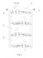
- CN104344413B (as shown in Figure 1 ) proposes to periodically reverse the flow direction of flue gas in the flue to remove the ash on the heat exchange tube.
- the flue wall 1' defines the flue divided into a plurality of flue sections by a plurality of flue gas dampers 3' horizontally orientated and vertically spaced, and a heat exchange tube bank (i.e., heating surface) 2' is arranged horizontally in each flue section.
- the opening state of each flue gas damper 3' is adjustable (by means of the flappers 4'), thereby allowing the flue gas flow direction in the flue to be periodically reversed, to thus remove the ash on the heat exchange tube (which is usually deposited on a leeward side of the tube).
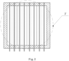
- each flue gas damper 3' extends horizontally to cross the entire flue section, as shown in Figure 2 , so that each individual flue gas damper has a big size, especially in terms of its frame (the long side may be as long as ten or twenty meters, and the short side may be as long as a few meters), which causes difficulties in the manufacture, installation, and maintenance of the flue gas damper. Moreover, the thermal expansion and contraction effect is significant, which further increases the difficulty of installation. Meanwhile, a big amount of materials (such as steel) is required to manufacture the frame, which leads to a high manufacturing cost. Most importantly, no matter how the flue gas dampers are adjusted, the flue gas must exchange heat with a part of the heating surface (that is, a part of the heat exchange tube bank).
- the flue gas temperature will be further reduced after the flue gas passes through the heating surface, which will easily cause condensation, produce acid rot, sticky dust and other problems which may hinder heat transfer and even block the heating surface.
- the flue gas velocity will gradually decrease along each layer of the horizontal flue section, due to the resistance of the heat exchange tube bank used as the heating surface, which leads to undesired ash accumulation or unsatisfactory ash removal from the downstream heating surface.
- the present invention is aimed to provide a heat exchange flue and a corresponding heat exchange device that can overcome at least one of the above-mentioned drawbacks.
- heating surface equals to "heat exchange tube bank”.
- the present invention first of all, by redesign the main flue as a "sandwich"-type structure with left and right side flues and a heating surface in the middle, and by designing the large-sized flue gas damper as small-sized flue gas dampers that are only installed in the left and right side flues, the structure and size of the flue gas damper is greatly simplified, thereby facilitating disassembly, assembly, and maintenance of the flue gas damper.
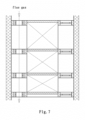
- the flue gas can directly pass the left and/or right side flue (as shown in Figure 7 ), without heat exchange with the heating surface, and thus the working load adjustment range can be maximized while ensuring a desired temperature of the flue gas and preventing condensation.
- a large space is provided at both ends of each horizontal flue section corresponding to each side flue, where access openings can be provided on the flue walls to facilitate the installation and maintenance of each layer of flue gas dampers and heating surface.
- each flue gas damper can be opened and closed independently, so that the flue gas flow path through the heat exchange section is diverse.
- the heights of horizontal flue sections gradually decrease from top to bottom, so as to ensure that the flue gas flow rate does not drop or drop too much when flowing downstream, to thus ensure no ash accumulation on the low temperature section of the heating surface.
- the present invention relates to a heat exchange flue, as shown in FIG. 3 , which has a top flue gas chamber 1, a bottom flue gas chamber 10 and a heat exchange section H located between the two chambers.
- the heat exchange section H includes a heat exchange tube bank (i.e., a heating surface) 4 in the middle, and a left side flue 5 and a right side flue 12 respectively on the left and right sides of the heat exchange tube bank 4.
- the heat exchange tube bank 4 is preferably oriented vertically, that is, its axis is substantially vertical, but the bank may also be horizontally oriented with substantially extending back and forth, or oriented in any orientation between the vertical orientation and substantially front-rear horizontal orientation.
- the axis of the heat exchange tube bank is positioned in a vertical plane extending substantially forward and backward, thereby allowing the flue gas to wash or flush the surface of the heat exchange tube laterally.
- the top flue gas chamber 1 is defined by the surrounding flue walls 20 and collects the flue gas from the upstream and allows the flue gas to flow into the left side flue 5 and/or the right side flue 12.
- the bottom flue gas chamber 10 is also defined by the surrounding flue walls 20 but collects the flue gas from the left side flue 5 and/or the right side flue 12 and discharges it downstream.
- the left and right side flues 5 and 12 are respectively located on the left and right sides of the heating surface 4, and are each in a vertical box shape (for example, with a rectangular cross-section when viewed from the top as shown in fig. 4 ), and are defined by the surrounding flue walls (e.g., the front flue wall, the rear flue wall, and the left/right side flue wall) and the heating surface 4.
- the surrounding flue walls e.g., the front flue wall, the rear flue wall, and the left/right side flue wall
- the left and right side flues 5, 12 each have a plurality of (at least two) flue gas dampers 3, and the flue gas dampers 3 in each side flue are vertically spaced apart, and the flue gas dampers 3 in the left side flue are horizontally aligned with the corresponding flue gas dampers in the right side flue.
- Each flue gas damper 3 has a flue gas damper frame 13 defining a flue gas port 2, and has a flue gas port opening and closing device capable of selectively opening and closing the flue gas port.
- the flue gas damper frame 13 is hollow out and is horizontally arranged.
- the door frame 13 has an outer periphery consistent with the cross-sectional shape of the left/ right side flues (for example, in the shape of rectangular, or other shapes), and air-tightly connected to the surrounding flue walls (for example, in case the frame is rectangular, three of its four sides are connected to the front flue wall, and the rear flue wall, and a corresponding one of the left and right side flue wall, respectively).
- the part of the frame corresponding to the heat exchange tube bank 4 (for example, the fourth side in case of a rectangular frame) is air-tightly connected to a substantially horizontal flue gas shield plate 6 which will be described below.
- the flue gas shield plate 6 is a plate made of e.g., steel, formed with holes to receive the heat exchange tubes air-tightly, in the case that the shield plate intersects with the heat exchange tube bank 4 of the heating surface, for example when the tube bank is arranged vertically; or formed with no holes in the case that the shield plate does not intersects with the heat exchange tube bank of the heating surface, such as when the tube bank is arranged horizontally.
- the flue gas shield plates 6 has its front and rear sides air-tightly fixed to the corresponding front and rear flue walls 20, and has its left and right sides air-tightly connected to the corresponding left and right side flue gas damper frame 13 respectively.
- each layer of the left and right side flue gas dampers 3 and the corresponding flue gas shield plate 6, in combination with an adjacent layer of the left and right side flue gas dampers 3 and the corresponding flue gas shield plates 6, define a horizontal flue section.
- the upper most flue gas shield plate 6 is formed with no holes, so that the flue gas from the top flue gas chamber 1 can only enter the left and/or right side flues through the top left side flue gas damper and/or right side flue gas damper, without directly entering the heating surface.
- access openings 7 can be provided in the flue walls near both ends of each horizontal flue section (as shown in Figure 1 ), so as to facilitate installation, maintenance and repair by an operator. With the access openings, the operator can easily access each side flue, so as to install each layer of flue gas dampers 3 and perform maintenance to the flue gas dampers 3 and the heating surface 4.
- each flue gas damper 3 has a flue gas port 2 (e.g., a rectangular opening as in the figure) defined by a flue gas damper frame 13, and has a corresponding flue gas port opening and closing device which includes: a rotating shaft 23; a flap member 22 fixedly connected to the rotating shaft 23 to rotate with it so as to close or open at least a part of the flue gas port; a plurality of supporting plates 21 for supporting the rotating shaft 23; and a rotating shaft driving device.
- a flue gas port 2 e.g., a rectangular opening as in the figure
- a flue gas damper frame 13 e.g., a rectangular opening as in the figure
- a corresponding flue gas port opening and closing device which includes: a rotating shaft 23; a flap member 22 fixedly connected to the rotating shaft 23 to rotate with it so as to close or open at least a part of the flue gas port; a plurality of supporting plates 21 for supporting the rotating shaft 23; and a rotating shaft driving device.
- the supporting plate 21 is in the shape of an elongated sheet, with two ends respectively fixedly connected to opposite sides of the flue gas damper frame
- the rotating shaft driving device includes: a bracket 19 stationary relative to the flue gas damper frame 13 (for example, the bracket 19 is fixed on the flue wall), and rocker arms 15 rotatably supported by the bracket 19.
- Each rocker arm has one end fixedly connected to the rotating shaft and the other end pivotally connected to an actuation rod 16 which is optionally connected to an actuator 24.
- the actuation rod 16 is moved manually (if there is no actuator 24), or by the actuator 24, to a predetermined position, thereby driving the rocker arms 15 to rotate relative to the bracket 19, and thus in turn driving the rotation shaft 23 to rotate, and then driving the flap member 22 to rotate, so as to close or open the flue gas port 2.
- the predetermined position can be achieved by a suitable stopper.
- the rotating shaft 23 can be actuated via other actuation configurations.
- the rotating shaft 23 can itself extend outside the flue or extend outside the flue by means of a rod connected to it, and then is connected to actuating mechanisms such as belt transmission mechanism, chain transmission mechanism, or gear transmission mechanism, so as to realize rotation.
- each flue gas damper frame 13 has a plurality of rotating shafts 23 arranged in parallel, and these shafts 23 are interlinked with each other so that all the flap members 22 carried by these rotating shafts can be opened or closed simultaneously like a window blind. In order to close the entire flue gas port, adjacent flap members 22 abut against each other or are partially overlapped with each other.
- each flue gas damper frame 13 has a group of stationary gates 62 spaced apart from each other, with adjacent gates defining a flue gas port.
- the flue gas port opening and closing device includes: a pulling rod 64; a group of sliding gates 63 fixed to the pulling rod 64 at intervals along the pulling rod; a plurality of support plates (similar to the support plate 21, not shown) for reciprocally supporting the pulling rod 64; and an actuating device 65 for driving the pulling rod to move back and forth.
- the stationary gates 62 and the sliding gates 63 are alternate to each other.
- the size of the sliding gate 63 is slightly larger than that of the flue gas port.
- the sliding gates 3 can block or open the flue gas port.
- the predetermined position can be achieved by a stopper.
- the flue gas port opening and closing devices of the flue gas damper frames on the left and right sides can be operated in linkage or independently.
- the heat exchange flue can be configured: to allow the flue gas to pass through each horizontal flue section sequentially along a serpentine path, as shown in Fig. 3 ; or such that all the flue gas dampers of the left side flue are in the open position and meanwhile all the flue gas dampers of the right side flue are in the closed position, and thus the flue gas does not pass through the heat exchange tube bank but directly flows through the left side flue, as shown in Fig.
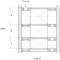
- the vertical distance between adjacent flue gas dampers 3 decreases from top to bottom, and accordingly the vertical heights of the horizontal flue sections decrease from top to bottom, as shown in Figures 3 , 7 , and 8 (especially see a>b>c in Figure 8 for easy understanding, a, b, and c respectively represent the vertical heights of the respective horizontal flue sections).
- the heat exchange tube bank on the heating surface is preferably oriented vertically, so as to further avoid ash accumulation due to gravity.
- other orientations are also possible, as long as the flue gas in the horizontal flue section wipes the heat exchange tube banks laterally.
- the present invention first of all, by redesign the main flue as a "sandwich"-type structure with left and right side flues and a heating surface in the middle, and designing the large flue gas damper as small-sized flue gas dampers that are only installed in the left and right side flues, the structure and size of the flue gas damper is greatly simplified, thereby facilitating disassembly, assembly, and maintenance of the glue gas door.
- the flue gas can directly pass the left and/or right side flue (as shown in Figure 7 ), without heat exchange with the heating surface, and thus the working load adjustment range can be maximized while ensuring a desired temperature of the flue gas and preventing the condensation.
- each horizontal flue section has a vertical height bigger than the downstream horizontal flue section, so as to ensure that the flue gas flow rate does not drop or drop too much when flowing downstream, to thus ensure no dust accumulation in the low temperature section of the heating surface.
Landscapes
- Engineering & Computer Science (AREA)
- Mechanical Engineering (AREA)
- General Engineering & Computer Science (AREA)
- Air Supply (AREA)
- Heat-Exchange Devices With Radiators And Conduit Assemblies (AREA)
Claims (15)
- Wärmetauscherschacht, der eine obere Abgaskammer (1), eine untere Abgaskammer (10) und einen zwischen den beiden Kammern (1, 10) angeordneten Wärmetauscherabschnitt (H) umfasst, wobei der Wärmetauscherabschnitt (H) ein Wärmetauscherrohrbündel (4) in der Mitte und einen linken Seitenschacht (5) und einen rechten Seitenschacht (12) jeweils auf der linken und rechten Seite des Wärmetauscherrohrbündels (4) umfasst;wobei die obere Abgaskammer (1) von den umgebenden Schachtwänden (20) begrenzt wird, die das stromaufwärts gerichtete Abgas sammeln und das Abgas in den linken Seitenschacht (5) und/oder den rechten Seitenschacht (12) strömen lassen, unddie untere Abgaskammer (10) ebenfalls durch die umgebenden Schachtwände (20) begrenzt ist, die das Abgas aus dem linken (5) und/oder dem rechten (12) Seitenschacht sammelt und stromabwärts ableitet, undder linke und der rechte Seitenschacht (5, 12) haben jeweils die Form eines vertikalen Kastens, der von den umgebenden Schachtwänden (20) und dem Wärmetauscherrohrbündel (4) begrenzt wird;der linke und der rechte Seitenschacht (5, 12) jeweils eine Vielzahl von Abgasklappen (3) aufweisen, und die Abgasklappen (3) in jedem Seitenschacht vertikal voneinander beabstandet sind, und die Abgasklappen (3) im linken Seitenschacht (5) horizontal mit den entsprechenden Abgasklappen (3) im rechten Seitenschacht (12) ausgerichtet sind, jede Abgasklappe (3) einen Abgasklappenrahmen (13) aufweist, der eine Abgasöffnung (2) definiert, und eine Abgasöffnungs- und Schließvorrichtung aufweist, die in der Lage ist, die Abgasöffnung (2) selektiv zu öffnen und zu schließen;wobei jeder Abgasklappenrahmen (13) hohl und horizontal angeordnet ist und eine Außenkontur aufweist, die mit der Querschnittsform des linken oder rechten Seitenschachts (5, 12) übereinstimmt, wobei die Umfangskanten des Abgasklappenrahmens (13) jeweils luftdicht mit den umgebenden Schachtwänden (20) verbunden sind, wobei der dem Wärmetauscherrohrbündel (4) entsprechende Teil des Abgasklappenrahmens (13) luftdicht mit einer im wesentlichen horizontalen Abgasabschirmplatte (6) verbunden ist;jede Abgasabschirmplatte (6) mit ihrer Vorder- und Rückseite luftdicht an den entsprechenden vorderen und hinteren Schachtwänden (20) befestigt ist und mit ihrer linken und rechten Seite luftdicht mit dem entsprechenden linken bzw. rechten Abgasklappenrahmen (13) verbunden ist, so dass jede Schicht der linken und rechten seitlichen Abgasklappen (3) und der entsprechenden Abgasabschirmplatte (6) in Kombination mit einer benachbarten Schicht der linken und rechten seitlichen Abgasklappen (3) und der entsprechenden Abgasabschirmplatten (6) einen horizontalen Abgasabschnitt definieren;das Wärmetauscherrohrbündel (4) so ausgerichtet ist, dass es sich mit einer der Abgasabschirmplatten (6) schneidet oder nicht schneidet; falls das Wärmetauscherrohrbündel (4) so ausgerichtet ist, dass es sich mit einer Abgasabschirmplatte (6) schneidet, ist diese Abgasabschirmplatte (6) mit Löchern zur luftdichten Aufnahme der Wärmetauscherrohre versehen.
- Wärmetauscherschacht nach Anspruch 1, wobei die oberste Abgasabschirmplatte (6) ohne Löcher ausgebildet ist, so dass das Abgas aus der oberen Abgaskammer (1) nur durch die oberste linke Abgasklappe (3) und/oder die oberste rechte Abgasklappe (3) in den linken und/oder rechten Seitenschächten (5, 12) eintreten kann, ohne direkt in das Wärmetauscherrohrbündel (4) zu gelangen.
- Wärmetauscherschacht nach Anspruch 1, wobei in den Schachtwänden (20) an beiden Enden jedes horizontalen Schachtabschnitts Zugangsöffnungen (7) vorgesehen sind, die den linken und rechten Seitenschächten (5, 12) entsprechen, so dass ein Bediener Zugang zu jedem Seitenschacht (5, 12) hat.
- Wärmetauscherschacht nach Anspruch 1, wobei
jede Abgasklappe (3) eine Abgasöffnung (2) aufweist, die durch einen Abgasklappenrahmen (13) definiert ist, und jede Vorrichtung zum Öffnen und Schließen der Abgasöffnung umfasst: eine rotierende Welle (23), ein Klappenelement (22), das fest mit der rotierenden Welle (23) verbunden ist, um sich mit ihr zu drehen, um zumindest einen Teil der Abgasöffnung (2) zu schließen oder zu öffnen, eine Vielzahl von Stützplatten (21) zum drehbaren Stützen der rotierenden Welle (23); und eine Antriebsvorrichtung (15, 16, 19, 24) der rotierenden Welle. - Wärmetauscherschacht nach Anspruch 4, wobei jede Stützplatte (21) die Form eines länglichen Blechs hat, dessen beide Enden jeweils fest mit gegenüberliegenden Seiten des jeweiligen Abgasklappenrahmens (13) verbunden sind.
- Wärmetauscherschacht nach Anspruch 4, wobei die Antriebsvorrichtung (15, 16, 19, 24) für die rotierende Welle umfasst: eine in Bezug auf den Abgasklappenrahmen (13) stationäre Halterung (19); Kipphebel (15), die drehbar von der Halterung (19) getragen werden, wobei jeder Kipphebel (15) mit einem Ende fest mit der rotierenden Welle (23) und mit dem anderen Ende schwenkbar mit einer Betätigungsstange (16) verbunden ist, die mit einem Stellglied (24) verbunden ist.
- Wärmetauscherschacht nach Anspruch 4, wobei sich die rotierende Welle (23) selbst außerhalb des Schachts (5, 12) erstreckt oder sich mittels einer mit ihr verbundenen Stange außerhalb des Schachts (5, 12) erstreckt und dann mit einem Riemenübertragungsmechanismus oder einem Kettenübertragungsmechanismus oder einem Zahnradübertragungsmechanismus als Antriebsvorrichtung für die rotierende Welle verbunden ist, so dass sie durch den Mechanismus drehbar ist.
- Wärmetauscherschacht nach Anspruch 4, wobei jeder Abgasklappenrahmen (13) mehrere parallel angeordnete rotierende Wellen (23) aufweist, die miteinander verbunden sind, so dass benachbarte Klappenelemente (22) aneinander stoßen können oder sich teilweise überlappen, um die gesamte Abgasöffnung (2) zu schließen.
- Wärmetauscherschacht nach Anspruch 1, wobeijeder Abgasklappenrahmen (13) eine Gruppe von stationären Toren (62) aufweist, die voneinander beabstandet sind, wobei benachbarte stationäre Tore (62) die Abgasöffnung (2) definieren; unddie Vorrichtung zum Öffnen und Schließen des Abgasanschlusses umfasst: eine Zugstange (64); eine Gruppe von Schiebetoren (63), die in Abständen entlang der Zugstange (64) an der Zugstange (64) befestigt sind; eine Vielzahl von Stützplatten zum hin- und hergehenden Stützen der Zugstange (64); und eine Antriebsvorrichtung (65) zum Antreiben der Zugstange, damit diese sich vor und zurück bewegt; unddie stationären Tore (62) und die Schiebetore (63) einander abwechseln, und jedes Schiebetor (63) eine Größe hat, die geringfügig größer ist als die der Abgasöffnung (2), so dass, wenn die Zugstange (64) in eine vorbestimmte Position gezogen wird,die Schiebetore (63) zumindest einen Teil der Abgasöffnung (2) blockieren oder öffnen können.
- Wärmetauscherschacht nach Anspruch 1, wobei die Öffnungs- und Schließvorrichtungen der Abgasklappenrahmen (13) jeweils im Verbund oder unabhängig voneinander betrieben werden.
- Wärmetauscherschacht nach Anspruch 10, wobei die Abgasklappen (3) konfigurierbar sind:so dass das Abgas im Falle mehrerer horizontaler Rauchabschnitte nacheinander durch jeden horizontalen Rauchabschnitt entlang eines Serpentinenwegs strömen kann; oderso dass alle Abgasklappen (3) des linken Seitenschachts (5) in der offenen Position sind und währenddessen alle Abgasklappen (3) des rechten Seitenschachts (12) in der geschlossenen Position sind, und somit das Abgas nicht durch das Wärmetauscherrohrbündel (4), sondern direkt durch den linken Seitenschacht (5) strömt; oderso dass alle Abgasklappen (3) des rechten Seitenschachts (12) in der offenen Position sind und währenddessen alle Abgasklappen (3) des linken Seitenschachts (5) in der geschlossenen Position sind, und somit das Abgas nicht durch das Wärmetauscherrohrbündel (4), sondern direkt durch den rechten Seitenschacht (12) strömt; oderalle Abgasklappen (3) in geöffneter Stellung sind, so dass das Abgas gleichzeitig durch den linken und den rechten Seitenschacht (5, 12) strömt, ohne durch das Wärmetauscherrohrbündel (4) zu gehen; oderdas Öffnen und Schließen der Abgasklappen (3) im linken und rechten Seitenschacht (5, 12) so einzustellen, dass das Abgas bei mehreren horizontalen Schachtabschnitten nur durch einen Teil und nicht durch alle horizontalen Schachtabschnitte strömt.
- Wärmetauscherschacht nach Anspruch 1, wobei die vertikalen Höhen der horizontalen Schachtabschnitte im Falle mehrerer horizontaler Schachtabschnitte von oben nach unten abnehmen.
- Wärmetauscherschacht nach Anspruch 1, wobei das Wärmetauscherrohrbündel (4) so ausgerichtet ist, dass ihre Achse in einer vertikalen Ebene liegt, die sich im Wesentlichen nach vorne und hinten erstreckt, wodurch das Abgas die Oberfläche des Wärmetauscherrohrs seitlich umspülen kann.
- Wärmetauschervorrichtung, die den Wärmetauscherschacht nach Anspruch 1 umfasst.
- Wärmeaustauschvorrichtung nach Anspruch 14, wobei die Vorrichtung ein Heizkessel ist.
Applications Claiming Priority (2)
| Application Number | Priority Date | Filing Date | Title |
|---|---|---|---|
| CN201910263998.7A CN111750370B (zh) | 2019-03-28 | 2019-03-28 | 换热烟道以及换热设备 |
| PCT/CN2019/105998 WO2020192035A1 (zh) | 2019-03-28 | 2019-09-16 | 换热烟道以及换热设备 |
Publications (3)
| Publication Number | Publication Date |
|---|---|
| EP3951264A1 EP3951264A1 (de) | 2022-02-09 |
| EP3951264A4 EP3951264A4 (de) | 2022-12-28 |
| EP3951264B1 true EP3951264B1 (de) | 2024-09-04 |
Family
ID=72611243
Family Applications (1)
| Application Number | Title | Priority Date | Filing Date |
|---|---|---|---|
| EP19921587.2A Active EP3951264B1 (de) | 2019-03-28 | 2019-09-16 | Wärmeaustauschanordnung und wärmeaustauschvorrichtung |
Country Status (4)
| Country | Link |
|---|---|
| US (1) | US12449125B2 (de) |
| EP (1) | EP3951264B1 (de) |
| CN (1) | CN111750370B (de) |
| WO (1) | WO2020192035A1 (de) |
Families Citing this family (7)
| Publication number | Priority date | Publication date | Assignee | Title |
|---|---|---|---|---|
| CN112902128A (zh) * | 2021-02-03 | 2021-06-04 | 聊城市鲁西化工工程设计有限责任公司 | 一种水管式余热锅炉及尾气处理系统 |
| CN115307168A (zh) * | 2021-05-08 | 2022-11-08 | 马成果 | 烟气脱硝调温烟道及锅炉 |
| CN113405083A (zh) * | 2021-07-16 | 2021-09-17 | 江苏太湖锅炉股份有限公司 | 一种抽屉式烟道受热面 |
| CN114526475A (zh) * | 2022-02-25 | 2022-05-24 | 西安西热锅炉环保工程有限公司 | 一种可调节换热面积的热管低温省煤器及其工作方法 |
| CN115164223B (zh) * | 2022-07-13 | 2024-07-02 | 洛阳新普石化设备开发有限公司 | 一种方便装卸的气封式零泄露挡板及其使用方法 |
| CN117109020A (zh) * | 2022-12-06 | 2023-11-24 | 江苏美标环保机械有限公司 | 一种用于脱硫脱硝设备的自动烟气挡板门 |
| CN121274713B (zh) * | 2025-12-09 | 2026-04-17 | 新疆西部明珠工程建设有限公司 | 一种防堵塞的卧式烟气换热装置 |
Family Cites Families (15)
| Publication number | Priority date | Publication date | Assignee | Title |
|---|---|---|---|---|
| DE621876C (de) | 1935-11-14 | Engelbert Jungeblodt Dipl Ing | Russreinigungseinrichtung an Rauchgasvorwaermern | |
| US2716021A (en) * | 1952-12-22 | 1955-08-23 | Babcock & Wilcox Co | Method of and damper apparatus for cleaning tube banks |
| US4033320A (en) * | 1974-07-15 | 1977-07-05 | Jury Gene R | Furnace and cold air return systems |
| US4207864A (en) * | 1978-06-08 | 1980-06-17 | General Electric Company | Damper |
| US4699317A (en) | 1984-04-18 | 1987-10-13 | Temperature Adjusters, Inc. | Heat exchanger flue |
| DE3533969A1 (de) * | 1985-09-24 | 1987-04-02 | Horst F Langner | Kaminaufsatz |
| US4999167A (en) * | 1989-06-20 | 1991-03-12 | Skelley Arthur P | Low temperature Nox /Sox removal apparatus |
| US20030056944A1 (en) * | 1999-09-23 | 2003-03-27 | Joseph C. Ferraro | External flue heat exchangers |
| US20080314260A1 (en) * | 2007-06-22 | 2008-12-25 | Paul Hardenburger | Dual damper control apparatus and method |
| CN104344413B (zh) * | 2013-08-02 | 2017-05-10 | 马成果 | 一种抗积灰结露和跟踪负荷的可控多向流对流换热烟道 |
| CN105546562A (zh) | 2016-01-29 | 2016-05-04 | 上海久试电力技术有限公司 | 控制烟温的烟道和控制方法以及烟道的改进方法 |
| CN205690416U (zh) * | 2016-01-29 | 2016-11-16 | 上海久试电力技术有限公司 | 控制烟温的烟道 |
| CN107449295B (zh) | 2016-06-01 | 2023-08-11 | 马成果 | 可实现反向冲刷清灰的固定式列管水管热交换器 |
| CN206959070U (zh) * | 2017-06-16 | 2018-02-02 | 宁波方太厨具有限公司 | 进风方向可调的吸油烟机 |
| CN209819568U (zh) * | 2019-03-28 | 2019-12-20 | 马成果 | 换热烟道以及换热设备 |
-
2019
- 2019-03-28 CN CN201910263998.7A patent/CN111750370B/zh active Active
- 2019-09-16 WO PCT/CN2019/105998 patent/WO2020192035A1/zh not_active Ceased
- 2019-09-16 EP EP19921587.2A patent/EP3951264B1/de active Active
- 2019-09-16 US US17/599,005 patent/US12449125B2/en active Active
Also Published As
| Publication number | Publication date |
|---|---|
| CN111750370B (zh) | 2025-03-25 |
| WO2020192035A1 (zh) | 2020-10-01 |
| CN111750370A (zh) | 2020-10-09 |
| EP3951264A4 (de) | 2022-12-28 |
| US20220178536A1 (en) | 2022-06-09 |
| EP3951264A1 (de) | 2022-02-09 |
| US12449125B2 (en) | 2025-10-21 |
Similar Documents
| Publication | Publication Date | Title |
|---|---|---|
| EP3951264B1 (de) | Wärmeaustauschanordnung und wärmeaustauschvorrichtung | |
| RU2643374C2 (ru) | Канал конвективного теплообмена | |
| TWI507643B (zh) | 可減少冷端積垢之再生型空氣預熱器 | |
| CN207316946U (zh) | 具有自动清灰功能的防堵型烟道换热器 | |
| WO2021179928A1 (zh) | 一种自洁式空气预热器 | |
| CN209819568U (zh) | 换热烟道以及换热设备 | |
| CN110822551B (zh) | 一种室内机及空调器 | |
| GB2049148A (en) | Heat exchanger tube support | |
| CN110822552B (zh) | 一种室内机及空调器 | |
| CN107062956A (zh) | 一种用于大容量烟气余热利用的螺旋鳍片管换热装置 | |
| CN110822550B (zh) | 一种室内机及空调器 | |
| US6497230B1 (en) | Air port damper | |
| CN222011966U (zh) | 一种能减少积灰的锅炉 | |
| CN113831003B (zh) | 一种控风可靠的玻璃钢化送风系统 | |
| CN107014223A (zh) | 大容量烟气余热利用低低温减排用防磨高效换热装置 | |
| CN120627113A (zh) | 一种能减少积灰的锅炉 | |
| US4403649A (en) | Omni-directional face-and-bypass coil | |
| CN110274256B (zh) | 一种无窜风蓄热式空气预热器 | |
| CN115597391A (zh) | 一种抗积灰可调温的可变对流烟道及加热炉 | |
| CN101625193A (zh) | 木材干燥装置节能型空气动力源系统 | |
| CN117006835B (zh) | 一种高效保质型粮食干燥系统 | |
| CN211176871U (zh) | 风压降尘回风换热螺旋清灰生物质烤烟炉 | |
| CN211178034U (zh) | 回风式螺旋清灰烤烟炉散热器 | |
| CN2932200Y (zh) | 常压卧式直水管三回程型煤热水锅炉 | |
| CN113819767A (zh) | 一种粗烟气预冷及烟气粉尘收集装置 |
Legal Events
| Date | Code | Title | Description |
|---|---|---|---|
| STAA | Information on the status of an ep patent application or granted ep patent |
Free format text: STATUS: THE INTERNATIONAL PUBLICATION HAS BEEN MADE |
|
| PUAI | Public reference made under article 153(3) epc to a published international application that has entered the european phase |
Free format text: ORIGINAL CODE: 0009012 |
|
| STAA | Information on the status of an ep patent application or granted ep patent |
Free format text: STATUS: REQUEST FOR EXAMINATION WAS MADE |
|
| 17P | Request for examination filed |
Effective date: 20210930 |
|
| AK | Designated contracting states |
Kind code of ref document: A1 Designated state(s): AL AT BE BG CH CY CZ DE DK EE ES FI FR GB GR HR HU IE IS IT LI LT LU LV MC MK MT NL NO PL PT RO RS SE SI SK SM TR |
|
| DAV | Request for validation of the european patent (deleted) | ||
| DAX | Request for extension of the european patent (deleted) | ||
| REG | Reference to a national code |
Ref country code: DE Ref legal event code: R079 Free format text: PREVIOUS MAIN CLASS: F23J0011000000 Ipc: F23J0015060000 Ref document number: 602019058538 Country of ref document: DE |
|
| A4 | Supplementary search report drawn up and despatched |
Effective date: 20221124 |
|
| RIC1 | Information provided on ipc code assigned before grant |
Ipc: F28F 13/08 20060101ALI20221118BHEP Ipc: F28F 19/00 20060101ALI20221118BHEP Ipc: F23J 11/00 20060101ALI20221118BHEP Ipc: F23J 15/06 20060101AFI20221118BHEP |
|
| STAA | Information on the status of an ep patent application or granted ep patent |
Free format text: STATUS: EXAMINATION IS IN PROGRESS |
|
| 17Q | First examination report despatched |
Effective date: 20230912 |
|
| GRAP | Despatch of communication of intention to grant a patent |
Free format text: ORIGINAL CODE: EPIDOSNIGR1 |
|
| STAA | Information on the status of an ep patent application or granted ep patent |
Free format text: STATUS: GRANT OF PATENT IS INTENDED |
|
| INTG | Intention to grant announced |
Effective date: 20240328 |
|
| GRAS | Grant fee paid |
Free format text: ORIGINAL CODE: EPIDOSNIGR3 |
|
| GRAA | (expected) grant |
Free format text: ORIGINAL CODE: 0009210 |
|
| STAA | Information on the status of an ep patent application or granted ep patent |
Free format text: STATUS: THE PATENT HAS BEEN GRANTED |
|
| AK | Designated contracting states |
Kind code of ref document: B1 Designated state(s): AL AT BE BG CH CY CZ DE DK EE ES FI FR GB GR HR HU IE IS IT LI LT LU LV MC MK MT NL NO PL PT RO RS SE SI SK SM TR |
|
| REG | Reference to a national code |
Ref country code: GB Ref legal event code: FG4D |
|
| REG | Reference to a national code |
Ref country code: CH Ref legal event code: EP |
|
| REG | Reference to a national code |
Ref country code: IE Ref legal event code: FG4D |
|
| REG | Reference to a national code |
Ref country code: DE Ref legal event code: R096 Ref document number: 602019058538 Country of ref document: DE |
|
| REG | Reference to a national code |
Ref country code: LT Ref legal event code: MG9D |
|
| REG | Reference to a national code |
Ref country code: NL Ref legal event code: MP Effective date: 20240904 |
|
| PG25 | Lapsed in a contracting state [announced via postgrant information from national office to epo] |
Ref country code: NO Free format text: LAPSE BECAUSE OF FAILURE TO SUBMIT A TRANSLATION OF THE DESCRIPTION OR TO PAY THE FEE WITHIN THE PRESCRIBED TIME-LIMIT Effective date: 20241204 |
|
| PG25 | Lapsed in a contracting state [announced via postgrant information from national office to epo] |
Ref country code: GR Free format text: LAPSE BECAUSE OF FAILURE TO SUBMIT A TRANSLATION OF THE DESCRIPTION OR TO PAY THE FEE WITHIN THE PRESCRIBED TIME-LIMIT Effective date: 20241205 Ref country code: PL Free format text: LAPSE BECAUSE OF FAILURE TO SUBMIT A TRANSLATION OF THE DESCRIPTION OR TO PAY THE FEE WITHIN THE PRESCRIBED TIME-LIMIT Effective date: 20240904 Ref country code: FI Free format text: LAPSE BECAUSE OF FAILURE TO SUBMIT A TRANSLATION OF THE DESCRIPTION OR TO PAY THE FEE WITHIN THE PRESCRIBED TIME-LIMIT Effective date: 20240904 |
|
| PG25 | Lapsed in a contracting state [announced via postgrant information from national office to epo] |
Ref country code: BG Free format text: LAPSE BECAUSE OF FAILURE TO SUBMIT A TRANSLATION OF THE DESCRIPTION OR TO PAY THE FEE WITHIN THE PRESCRIBED TIME-LIMIT Effective date: 20240904 |
|
| PG25 | Lapsed in a contracting state [announced via postgrant information from national office to epo] |
Ref country code: LV Free format text: LAPSE BECAUSE OF FAILURE TO SUBMIT A TRANSLATION OF THE DESCRIPTION OR TO PAY THE FEE WITHIN THE PRESCRIBED TIME-LIMIT Effective date: 20240904 |
|
| PG25 | Lapsed in a contracting state [announced via postgrant information from national office to epo] |
Ref country code: HR Free format text: LAPSE BECAUSE OF FAILURE TO SUBMIT A TRANSLATION OF THE DESCRIPTION OR TO PAY THE FEE WITHIN THE PRESCRIBED TIME-LIMIT Effective date: 20240904 |
|
| PG25 | Lapsed in a contracting state [announced via postgrant information from national office to epo] |
Ref country code: ES Free format text: LAPSE BECAUSE OF FAILURE TO SUBMIT A TRANSLATION OF THE DESCRIPTION OR TO PAY THE FEE WITHIN THE PRESCRIBED TIME-LIMIT Effective date: 20240904 Ref country code: RS Free format text: LAPSE BECAUSE OF FAILURE TO SUBMIT A TRANSLATION OF THE DESCRIPTION OR TO PAY THE FEE WITHIN THE PRESCRIBED TIME-LIMIT Effective date: 20241204 |
|
| PG25 | Lapsed in a contracting state [announced via postgrant information from national office to epo] |
Ref country code: RS Free format text: LAPSE BECAUSE OF FAILURE TO SUBMIT A TRANSLATION OF THE DESCRIPTION OR TO PAY THE FEE WITHIN THE PRESCRIBED TIME-LIMIT Effective date: 20241204 Ref country code: PL Free format text: LAPSE BECAUSE OF FAILURE TO SUBMIT A TRANSLATION OF THE DESCRIPTION OR TO PAY THE FEE WITHIN THE PRESCRIBED TIME-LIMIT Effective date: 20240904 Ref country code: NO Free format text: LAPSE BECAUSE OF FAILURE TO SUBMIT A TRANSLATION OF THE DESCRIPTION OR TO PAY THE FEE WITHIN THE PRESCRIBED TIME-LIMIT Effective date: 20241204 Ref country code: LV Free format text: LAPSE BECAUSE OF FAILURE TO SUBMIT A TRANSLATION OF THE DESCRIPTION OR TO PAY THE FEE WITHIN THE PRESCRIBED TIME-LIMIT Effective date: 20240904 Ref country code: HR Free format text: LAPSE BECAUSE OF FAILURE TO SUBMIT A TRANSLATION OF THE DESCRIPTION OR TO PAY THE FEE WITHIN THE PRESCRIBED TIME-LIMIT Effective date: 20240904 Ref country code: GR Free format text: LAPSE BECAUSE OF FAILURE TO SUBMIT A TRANSLATION OF THE DESCRIPTION OR TO PAY THE FEE WITHIN THE PRESCRIBED TIME-LIMIT Effective date: 20241205 Ref country code: FI Free format text: LAPSE BECAUSE OF FAILURE TO SUBMIT A TRANSLATION OF THE DESCRIPTION OR TO PAY THE FEE WITHIN THE PRESCRIBED TIME-LIMIT Effective date: 20240904 Ref country code: ES Free format text: LAPSE BECAUSE OF FAILURE TO SUBMIT A TRANSLATION OF THE DESCRIPTION OR TO PAY THE FEE WITHIN THE PRESCRIBED TIME-LIMIT Effective date: 20240904 Ref country code: BG Free format text: LAPSE BECAUSE OF FAILURE TO SUBMIT A TRANSLATION OF THE DESCRIPTION OR TO PAY THE FEE WITHIN THE PRESCRIBED TIME-LIMIT Effective date: 20240904 |
|
| REG | Reference to a national code |
Ref country code: AT Ref legal event code: MK05 Ref document number: 1720745 Country of ref document: AT Kind code of ref document: T Effective date: 20240904 |
|
| PG25 | Lapsed in a contracting state [announced via postgrant information from national office to epo] |
Ref country code: NL Free format text: LAPSE BECAUSE OF FAILURE TO SUBMIT A TRANSLATION OF THE DESCRIPTION OR TO PAY THE FEE WITHIN THE PRESCRIBED TIME-LIMIT Effective date: 20240904 |
|
| PG25 | Lapsed in a contracting state [announced via postgrant information from national office to epo] |
Ref country code: PT Free format text: LAPSE BECAUSE OF FAILURE TO SUBMIT A TRANSLATION OF THE DESCRIPTION OR TO PAY THE FEE WITHIN THE PRESCRIBED TIME-LIMIT Effective date: 20250106 Ref country code: IS Free format text: LAPSE BECAUSE OF FAILURE TO SUBMIT A TRANSLATION OF THE DESCRIPTION OR TO PAY THE FEE WITHIN THE PRESCRIBED TIME-LIMIT Effective date: 20250104 |
|
| PG25 | Lapsed in a contracting state [announced via postgrant information from national office to epo] |
Ref country code: RO Free format text: LAPSE BECAUSE OF FAILURE TO SUBMIT A TRANSLATION OF THE DESCRIPTION OR TO PAY THE FEE WITHIN THE PRESCRIBED TIME-LIMIT Effective date: 20240904 Ref country code: SM Free format text: LAPSE BECAUSE OF FAILURE TO SUBMIT A TRANSLATION OF THE DESCRIPTION OR TO PAY THE FEE WITHIN THE PRESCRIBED TIME-LIMIT Effective date: 20240904 |
|
| PG25 | Lapsed in a contracting state [announced via postgrant information from national office to epo] |
Ref country code: EE Free format text: LAPSE BECAUSE OF FAILURE TO SUBMIT A TRANSLATION OF THE DESCRIPTION OR TO PAY THE FEE WITHIN THE PRESCRIBED TIME-LIMIT Effective date: 20240904 Ref country code: AT Free format text: LAPSE BECAUSE OF FAILURE TO SUBMIT A TRANSLATION OF THE DESCRIPTION OR TO PAY THE FEE WITHIN THE PRESCRIBED TIME-LIMIT Effective date: 20240904 |
|
| PG25 | Lapsed in a contracting state [announced via postgrant information from national office to epo] |
Ref country code: CZ Free format text: LAPSE BECAUSE OF FAILURE TO SUBMIT A TRANSLATION OF THE DESCRIPTION OR TO PAY THE FEE WITHIN THE PRESCRIBED TIME-LIMIT Effective date: 20240904 |
|
| PG25 | Lapsed in a contracting state [announced via postgrant information from national office to epo] |
Ref country code: SK Free format text: LAPSE BECAUSE OF FAILURE TO SUBMIT A TRANSLATION OF THE DESCRIPTION OR TO PAY THE FEE WITHIN THE PRESCRIBED TIME-LIMIT Effective date: 20240904 Ref country code: IT Free format text: LAPSE BECAUSE OF FAILURE TO SUBMIT A TRANSLATION OF THE DESCRIPTION OR TO PAY THE FEE WITHIN THE PRESCRIBED TIME-LIMIT Effective date: 20240904 |
|
| REG | Reference to a national code |
Ref country code: CH Ref legal event code: PL |
|
| PG25 | Lapsed in a contracting state [announced via postgrant information from national office to epo] |
Ref country code: LU Free format text: LAPSE BECAUSE OF NON-PAYMENT OF DUE FEES Effective date: 20240916 |
|
| REG | Reference to a national code |
Ref country code: DE Ref legal event code: R097 Ref document number: 602019058538 Country of ref document: DE |
|
| PG25 | Lapsed in a contracting state [announced via postgrant information from national office to epo] |
Ref country code: MC Free format text: LAPSE BECAUSE OF FAILURE TO SUBMIT A TRANSLATION OF THE DESCRIPTION OR TO PAY THE FEE WITHIN THE PRESCRIBED TIME-LIMIT Effective date: 20240904 |
|
| PG25 | Lapsed in a contracting state [announced via postgrant information from national office to epo] |
Ref country code: DK Free format text: LAPSE BECAUSE OF FAILURE TO SUBMIT A TRANSLATION OF THE DESCRIPTION OR TO PAY THE FEE WITHIN THE PRESCRIBED TIME-LIMIT Effective date: 20240904 |
|
| REG | Reference to a national code |
Ref country code: BE Ref legal event code: MM Effective date: 20240930 |
|
| PLBE | No opposition filed within time limit |
Free format text: ORIGINAL CODE: 0009261 |
|
| STAA | Information on the status of an ep patent application or granted ep patent |
Free format text: STATUS: NO OPPOSITION FILED WITHIN TIME LIMIT |
|
| PG25 | Lapsed in a contracting state [announced via postgrant information from national office to epo] |
Ref country code: BE Free format text: LAPSE BECAUSE OF NON-PAYMENT OF DUE FEES Effective date: 20240930 |
|
| PG25 | Lapsed in a contracting state [announced via postgrant information from national office to epo] |
Ref country code: CH Free format text: LAPSE BECAUSE OF NON-PAYMENT OF DUE FEES Effective date: 20240930 |
|
| PG25 | Lapsed in a contracting state [announced via postgrant information from national office to epo] |
Ref country code: IE Free format text: LAPSE BECAUSE OF NON-PAYMENT OF DUE FEES Effective date: 20240916 |
|
| 26N | No opposition filed |
Effective date: 20250605 |
|
| GBPC | Gb: european patent ceased through non-payment of renewal fee |
Effective date: 20241204 |
|
| PG25 | Lapsed in a contracting state [announced via postgrant information from national office to epo] |
Ref country code: SE Free format text: LAPSE BECAUSE OF FAILURE TO SUBMIT A TRANSLATION OF THE DESCRIPTION OR TO PAY THE FEE WITHIN THE PRESCRIBED TIME-LIMIT Effective date: 20240904 |
|
| PGFP | Annual fee paid to national office [announced via postgrant information from national office to epo] |
Ref country code: DE Payment date: 20250919 Year of fee payment: 7 |
|
| PG25 | Lapsed in a contracting state [announced via postgrant information from national office to epo] |
Ref country code: GB Free format text: LAPSE BECAUSE OF NON-PAYMENT OF DUE FEES Effective date: 20241204 |
|
| PG25 | Lapsed in a contracting state [announced via postgrant information from national office to epo] |
Ref country code: FR Free format text: LAPSE BECAUSE OF NON-PAYMENT OF DUE FEES Effective date: 20241104 |
|
| PG25 | Lapsed in a contracting state [announced via postgrant information from national office to epo] |
Ref country code: CY Free format text: LAPSE BECAUSE OF FAILURE TO SUBMIT A TRANSLATION OF THE DESCRIPTION OR TO PAY THE FEE WITHIN THE PRESCRIBED TIME-LIMIT; INVALID AB INITIO Effective date: 20190916 |
|
| PG25 | Lapsed in a contracting state [announced via postgrant information from national office to epo] |
Ref country code: HU Free format text: LAPSE BECAUSE OF FAILURE TO SUBMIT A TRANSLATION OF THE DESCRIPTION OR TO PAY THE FEE WITHIN THE PRESCRIBED TIME-LIMIT; INVALID AB INITIO Effective date: 20190916 |