EP3951268B1 - Procédé de fonctionnement d'une plaque de cuisson - Google Patents
Procédé de fonctionnement d'une plaque de cuisson Download PDFInfo
- Publication number
- EP3951268B1 EP3951268B1 EP21188675.9A EP21188675A EP3951268B1 EP 3951268 B1 EP3951268 B1 EP 3951268B1 EP 21188675 A EP21188675 A EP 21188675A EP 3951268 B1 EP3951268 B1 EP 3951268B1
- Authority
- EP
- European Patent Office
- Prior art keywords
- cooking
- hob
- display means
- power supply
- presence sensor
- Prior art date
- Legal status (The legal status is an assumption and is not a legal conclusion. Google has not performed a legal analysis and makes no representation as to the accuracy of the status listed.)
- Active
Links
Images
Classifications
-
- F—MECHANICAL ENGINEERING; LIGHTING; HEATING; WEAPONS; BLASTING
- F24—HEATING; RANGES; VENTILATING
- F24C—DOMESTIC STOVES OR RANGES ; DETAILS OF DOMESTIC STOVES OR RANGES, OF GENERAL APPLICATION
- F24C7/00—Stoves or ranges heated by electric energy
- F24C7/08—Arrangement or mounting of control or safety devices
- F24C7/082—Arrangement or mounting of control or safety devices on ranges, e.g. control panels, illumination
- F24C7/083—Arrangement or mounting of control or safety devices on ranges, e.g. control panels, illumination on tops, hot plates
-
- H—ELECTRICITY
- H05—ELECTRIC TECHNIQUES NOT OTHERWISE PROVIDED FOR
- H05B—ELECTRIC HEATING; ELECTRIC LIGHT SOURCES NOT OTHERWISE PROVIDED FOR; CIRCUIT ARRANGEMENTS FOR ELECTRIC LIGHT SOURCES, IN GENERAL
- H05B6/00—Heating by electric, magnetic or electromagnetic fields
- H05B6/02—Induction heating
- H05B6/06—Control, e.g. of temperature, of power
- H05B6/062—Control, e.g. of temperature, of power for cooking plates or the like
-
- H—ELECTRICITY
- H05—ELECTRIC TECHNIQUES NOT OTHERWISE PROVIDED FOR
- H05B—ELECTRIC HEATING; ELECTRIC LIGHT SOURCES NOT OTHERWISE PROVIDED FOR; CIRCUIT ARRANGEMENTS FOR ELECTRIC LIGHT SOURCES, IN GENERAL
- H05B6/00—Heating by electric, magnetic or electromagnetic fields
- H05B6/02—Induction heating
- H05B6/10—Induction heating apparatus, other than furnaces, for specific applications
- H05B6/12—Cooking devices
- H05B6/1209—Cooking devices induction cooking plates or the like and devices to be used in combination with them
- H05B6/1218—Cooking devices induction cooking plates or the like and devices to be used in combination with them with arrangements using lights for heating zone state indication
-
- H—ELECTRICITY
- H05—ELECTRIC TECHNIQUES NOT OTHERWISE PROVIDED FOR
- H05B—ELECTRIC HEATING; ELECTRIC LIGHT SOURCES NOT OTHERWISE PROVIDED FOR; CIRCUIT ARRANGEMENTS FOR ELECTRIC LIGHT SOURCES, IN GENERAL
- H05B2213/00—Aspects relating both to resistive heating and to induction heating, covered by H05B3/00 and H05B6/00
- H05B2213/05—Heating plates with pan detection means
Definitions
- the invention relates to a method for operating a hob with a flat hob plate and heating devices on the hob plate.
- a hob with illuminated displays is known.
- a rotary knob that can be illuminated is provided to adjust the power of a heating device on a hob. This can provide information and operating assistance to an operator.
- the invention is based on the object of creating a method as mentioned above with which problems of the prior art can be avoided and in particular a safe and instinctive operation of a hob as well as its advantageous operation is possible.
- the hob has a flat hob plate and heating devices on this hob plate or underneath. These can be different heating devices, advantageously induction heating coils. It also has an operating device for the hob with operating elements, the operating elements being at least partially manually operable rotary knobs. They can be arranged in particular on a vertical control panel in front of and below the level of the hob plate. Knob display means are provided on at least one rotary knob, advantageously LEDs or lamps, particularly advantageously on the front thereof. At least one display or knob display means can be provided per rotary knob. Partial segments, color gradients or color changes depending on residual heat are also conceivable.
- Further operating elements can advantageously be touch switches or touch sensors, as are known, for example, in a capacitive design.
- the operating device of the hob has at least one such operating element on or under the hob plate. Additionally or alternatively, one or more operating elements can be located on or on the rotary knob, or the rotary knobs themselves form the operating elements of the hob.
- the hob also has hob display means on or under the hob plate, which are designed to illuminate through the hob plate. They can also be designed in a known way, in particular have LEDs. They can be part of the operating device or be independent.
- the hob has pan detection means that are advantageously arranged under the hob plate.
- pan detection means that are advantageously arranged under the hob plate.
- sensor means under the hob plate on cooking areas that can inductively or capacitively detect a pot on the cooking area.
- Induction heating coils are advantageous, as they can also form the aforementioned heating devices, i.e. offer both functions.
- the hob has a power supply to supply the heating devices with power, either as simple switches or as power electronics or power semiconductors for induction heating coils. They preferably work with a power level specified by the control device.
- the hob has a presence sensor, which is advantageously built into it, for example on or under the hob plate or on an aforementioned control panel. It can also be formed by integrated touch sensors. Alternatively, it can be connected to an associated presence sensor, which is arranged elsewhere outside the hob, for example on an extractor hood or on a cupboard above it, or positioned elsewhere in the environment. Communication can advantageously take place wirelessly.
- the hob has a power supply for the operating device, and possibly also for the presence sensor if it is integrated in the hob or is part of it. This can be or have a switching power supply. This power supply advantageously has low energy consumption when the hob is in standby mode, i.e. not in use.
- the voltage supply and the power supply are designed separately, i.e. by different components or different functional units. They can also be arranged on different circuit boards under certain circumstances.
- the at least one presence sensor can be arranged on one of the rotary knobs or directly next to it, advantageously at a distance of less than 10 cm or even less than 5 cm.
- the advantage of mounting it in this location is that the rotary knob itself or the control panel on which it is arranged is directed into the room and can therefore much better detect the presence of an approaching person.
- a single presence sensor can be provided for the entire hob. This alone should be sufficient to detect the approach of an operator, both at a short distance such as 10 cm to 50 cm and at a long distance such as 1 m to 5 m. If the distance between the operator and the presence sensor is detected to be below a predetermined limit distance, which can in particular be less than 2 m or less than 50 cm, the presence sensor activates the hob display means and/or the toggle display means. For this purpose, it also activates a control of the operating device or the hob accordingly, or this controls it. and evaluates it, wherein the control then activates, in particular illuminates, the toggle display means according to the invention.
- a presence sensor can be designed as known from motion detectors, but also capacitively using capacitive sensors, for example. Even the aforementioned capacitive touch switches can form a presence sensor, which can then detect an operator at a relatively short distance such as 3 cm to 20 cm, especially if they bend over the hob when putting a pot on.
- a circuit board for the hob display means can preferably be provided under the hob plate, on which certain components are arranged.
- the aforementioned additional control elements can also be arranged here.
- the control of the operating device can be arranged on this circuit board for the hob display means or on a separate circuit board directly behind the rotary knobs. This control can advantageously be the entire hob control, so that no further control is required.
- the heating devices on the hob plate form defined cooking zones, in particular at least partially per cooking zone.
- at least one rotary knob for power adjustment is assigned to at least one heating device, whereby each heating device can be assigned exactly one separate rotary knob intended only for this heating device.
- the heating devices can be induction heating coils, wherein preferably these induction heating coils then also form the aforementioned pot detection means, so that they can detect pots inductively.
- the hob is operated in a standby mode in which all heating devices and the power supply are switched off, in particular also the pan detection means.
- the hob display means are also switched off.
- the hob is operated in a cooking mode in which the power supply is switched on and at least one heating device can be supplied with power to heat a pan placed above it, wherein preferably at least one hob display means is also switched on.
- the power supply can operate the pan detection means if these are formed by induction heating coils as described above.
- the presence sensor is active and is supplied with power from the power supply, which is switched on and activated.
- One of the heating devices can be activated or operated and heat, but it does not have to.
- the following steps are carried out.
- an operator approaches the presence sensor, which is also activated in standby mode. If the operator is less than a limit distance from the presence sensor, in particular less than 2 m or less than 50 cm, the presence sensor activates the toggle display means, and possibly also the hob display means.
- the power supply can be activated with the pot detection, and after a pot is detected, the display means can be activated. This means that information relating to the hob or the status of the hob can be output to the operator or the information can be displayed to the operator.
- information can be displayed, in particular relating to the detected size of the pots, residual heat on a cooking area according to a known hot indicator or the like.
- the hob can be switched from standby mode to cooking mode, whereupon the pot detection system searches for pots placed on the hob plate.
- the pot detection means are supplied with power from the power supply. In the case of induction heating coils as pot detection means, it is necessary that the power supply has been switched on. However, they do not actually have to heat, they only have to carry out pot detection. Pots placed on the hob plate and detected by the pot detection system can then be displayed with their corresponding position on the corresponding hob display means and/or knob display means.
- the hob indicators and/or the knob indicators can be deactivated either immediately or after a predefined waiting time.
- the power supply can then also be switched off again so that the hob is operated in standby mode again. The pan detection system is then no longer needed.
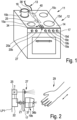
- Fig.1 is an oblique view of a hob 11 on a so-called stove 12, i.e. with an oven underneath, whereby the hob could also be installed alone.
- the hob 11 has a hob plate 14, for example made of known translucent reddish-brown glass ceramic.
- Four distributed cooking zones 15a to 15d are provided, as is known from the prior art. Each of the four cooking zones 15a to 15d is formed by an induction heating coil of a corresponding size, which is arranged below the hob plate 14.
- a pot 16 is placed on the cooking zone 15b at the rear left.
- the corresponding induction heating coil 15c' is shown for illustration purposes. It is connected to a power supply 38.
- a control panel 17 is arranged at the front of the stove 12 or the hob 11 below the level of the hob plate 14.
- the control panel 17 In the right-hand area of the control panel 17 there are four rotary knobs 19a to 19d for the hob 12.
- Each of the rotary knobs 19a to 19d is assigned to a cooking zone 15a to 15d and thus to the induction heating coil associated with it for operation.
- two rotary knobs 20a and 20b are provided for the functions of the oven arranged under the hob 11. This will not be discussed here.
- a presence sensor 27 is arranged between the two groups of rotary knobs 19 and 20.
- This can be designed, for example, like a conventional motion detector, alternatively it can be designed like a reflex light barrier or as a capacitive presence sensor. Its range or a distance that can serve as a limit distance for the distance to an operator can be between a few centimeters and a few meters, and this can possibly also be adjusted or individually set via a connected control 25.
- the presence sensor 27 could also be arranged directly on the rotary knob 19b or on one of the rotary knobs 19 or 20. As a further alternative, it can be integrated in the operating unit 34 and preferably use the existing operating elements or sensors or touch sensors.
- a connecting cable 13 extends schematically from the rear to the hob 12. It is connected to a left-hand power supply 38, with which the induction heating coils of the hobs 15a to 15d are supplied with power in a known manner.
- the power supply 38 has a conventional power electronics for induction heating coils.
- the connecting cable 13 is connected to a voltage supply 40 for the control 25 and above all for an operating device 34.
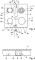
- the operating device 34 is provided in the front middle area of the hob plate 14. It has several illuminated operating elements 35, with the Fig.3 a control element 35b is shown and illuminated at the rear left. These control elements 35 are advantageously designed as capacitive touch switches, as is known from the prior art.
- the power supply 40 also serves to supply the presence sensor 27 and possible further displays or illuminated displays.
- Such further illuminated displays are, according to one possibility, as illuminated displays 33a in front of the cooking area 15a on the left front in Fig.3 activated. They can represent a locally assigned hot indicator, i.e. signal to an operator that this cooking zone 15a still has a temperature above 40°C or 50°C, as is the case with a normal hot indicator.
- a hot indicator could also be provided as an illuminated display in the area of the operating device 34 and be arranged there for the cooking zone 15a on the left front.
- the light indicators 33b surround the cooking area 15b in the form of a circular segment at a small distance.
- the induction heating coil as a pot detection means has detected the presence of the pot 16 on it. They do not form a hot indicator but indicate that a pot has been detected.
- the detection of the pot 16 can be displayed on the left rear control element 35b on the operating device 34 by its illumination, as shown in the Fig.3 shows.
- the control 25 is always supplied with power by the power supply 40, even if the hob 12 is switched off or in standby mode. Furthermore, the power supply 40 also supplies the presence sensor 27 with power or voltage so that it always works. If an operator approaches the presence sensor at a distance below a predetermined limit distance, the presence sensor 27 detects this. This limit distance can be less than 2 m or even less than 50 cm. In the present case, the Fig.2 This is a hand 29 of an operator that approaches the presence sensor 27 below the limit distance, for example because it moves towards a rotary knob 19 on the front panel 21.
- This rotary knob 19 can adjust a conventional power control device 22 by means of a shaft 21, which is connected to the control 25 in order to set a power of one of the cooking zones 15a to 15d or their induction heating coils.
- the control 25 can then activate different display options. On the one hand, it can activate a knob display means 36 on the front of the rotary knob 19, advantageously implemented by an LED, for Fig.2 shown lights.
- the knob display means 36 is connected to the control 25 by means of a connecting cable 37 within the rotary knob 19 and within the rotary axis 21, and can therefore be controlled by it. For example, it can be indicated that the presence of the operator or their hand 29 has been detected.
- the hot indicator 33a when the presence of an operator is detected by the presence sensor 27, the hot indicator 33a can also be activated, which was previously deactivated because the hob 12 was switched off in standby mode. This can serve to ensure that the hot indicator of the light indicators 33a does not have to be operated when no operator is nearby. Then there is also no danger of an operator burning or injuring themselves here.
- the indicator lights 33b on the cooking area 15b could light up to indicate to an operator that the pot 16 has been detected by the cooking area 12.
- the control 25 switches on the power supply 38 after detecting the presence of the operator. This is necessary for controlling the induction heating coils on the cooking areas 15a to 15d.
- the control 25 can now cause the induction heating coils to work as a pot detection device in accordance with their usual pot detection function, which is known from the prior art.
- the induction heating coil of the cooking area 15b will detect the pot 16, and this is indicated by the light displays 33b.
- An additional or alternative display of the detected pot 16 can be made on the rotary knob 19b by means of the knob display means 36b, so that this only lights up when a pot 16 was also placed on the cooking area 15b associated with the rotary knob 19b and has been detected.
- the light indicators 33, 35 and 36 are only activated and thus displayed when the operator has approached the stove 11 or the hob 12 at a distance below the limit distance.
- the special feature here is that not only is the detection of presence indicated in some way, for example by means of the toggle indicator 36b or the light indicators 33a as a hot indicator, but that the pan detection is started.
- the power supply 38 for the induction heating coils must first be switched on so that the induction heating coils can work as a pan detection device.
- the power supply alone is not sufficient or not designed to operate the induction heating coils as a pan detection device.
- the power control device 22 is arranged on the same circuit board LP1 as the control 25. All power control devices of the control panel 17 are advantageously arranged on this circuit board LP1, or at least those that belong to one of the groups of rotary knobs 19 or 20.
- the control 25 can then be connected to the operating device 34 by means of a cable or the like.
- the Fig.4 shows an arrangement of the operating device 34 with the illuminated operating elements 35 below the hob plate 14.
- the operating device 34 is arranged on a circuit board LP2.
- the control 25 can also be arranged on this, as indicated by the dashed line, and not on the circuit board LP1 of the power control devices 22.
- the hob 12 In the idle state after connecting the hob 12 to the connection cable 13, the hob 12 is in standby mode. If the power supply 38 is then switched on, for example by switching on the hob 12 or by operating an ON switch, it is in Cooking mode, into which it has changed from standby mode. In cooking mode, it is not necessary to cook or operate one of the induction heating coils for heating. In the invention, it is also not necessary for the hob 12 to be switched from standby mode to cooking mode after the presence of an operator has been detected by the presence sensor 27. This is only the case if it is considered necessary for certain reasons, or in order to activate the induction heating coils of the cooking zones 15 for the function as a pan detection means.
Landscapes
- Physics & Mathematics (AREA)
- Electromagnetism (AREA)
- Engineering & Computer Science (AREA)
- Chemical & Material Sciences (AREA)
- Combustion & Propulsion (AREA)
- Mechanical Engineering (AREA)
- General Engineering & Computer Science (AREA)
- Electric Stoves And Ranges (AREA)
- Induction Heating Cooking Devices (AREA)
Claims (12)
- Procédé de fonctionnement d'une table de cuisson (11), la table de cuisson (11) comprenant :- une plaque de cuisson plane (14) et des dispositifs de chauffage sur ou sous la plaque de cuisson (14),- un dispositif de commande (34) pour la table de cuisson (11) avec des éléments de commande (19, 19b, 20, 35, 35b), les éléments de commande présentant des manettes rotatives (19, 19b, 20) actionnables manuellement, en particulier disposées sur un panneau de commande vertical (17) devant et en dessous du plan de la plaque de cuisson (14),- des moyens d'affichage de la plaque de cuisson (33, 33a, 33b, 35, 35b) sur la plaque de cuisson (14), qui sont conçus pour éclairer à travers la plaque de cuisson (14),où :- le dispositif de commande (34) de la table de cuisson (11) présente au moins un élément de commande (19, 19b, 20, 35, 35b) ou les manettes rotatives (19, 19b, 20) sur la plaque de cuisson (14),- la table de cuisson (11) comporte des moyens de détection de casserole,- la table de cuisson (11) présente une alimentation en puissance (38) pour alimenter les dispositifs de chauffage en puissance, de préférence avec un niveau de puissance prédéfini par le dispositif de commande (34),- la table de cuisson (11) présente un capteur de présence (27) ou est reliée à un capteur de présence (27) qui lui est associé,- la table de cuisson (11) présente une alimentation électrique (40) pour le dispositif de commande (34) et pour le capteur de présence (27),- des moyens d'affichage de manette (36, 36b) sont prévus sur au moins une manette rotative (19, 19b, 20),caractérisé en ce que la table de cuisson (11)d'une part, elle fonctionne dans un mode d'attente dans lequel tous les dispositifs de chauffage et l'alimentation en puissance (38) sont éteints, de préférence également les moyens d'affichage de la table de cuisson (33, 33a, 33b, 35, 35b) sont éteints, etd'autre part, dans un mode de cuisson dans lequel l'alimentation électrique (38) est activée et au moins un dispositif de chauffage peut être alimenté en puissance pour chauffer une casserole (16) placée au-dessus de lui,- dans lequel, en mode d'attente, le capteur de présence (27) est actif et est alimenté par l'alimentation électrique (40), l'alimentation électrique (40) étant en marche et activée,- en mode cuisson, l'alimentation en puissance (38) est activée et activée,dans lequel, à partir d'une table de cuisson (11) fonctionnant en mode veille, un opérateur (29) s'approche du capteur de présence (27) et, lorsque l'opérateur (29) est à une distance du capteur de présence (27) inférieure à une distance limite, le capteur de présence (27) active les moyens d'affichage à manette (36, 36b) pour délivrer une information à l'opérateur (29) ou afficher l'information à l'opérateur (29), l'information concernant la table de cuisson (11) ou l'état de la table de cuisson (11).
- Procédé selon la revendication 1, caractérisé en ce que la distance limite est inférieure à 2 m, de préférence inférieure à 50 cm.
- Procédé selon la revendication 1 ou 2, caractérisé en ce que la table de cuisson (11) comprend un moyen d'affichage de table de cuisson (33, 33a, 33b, 35, 35b), dans lequel, dans le mode de cuisson, au moins un moyen d'affichage de table de cuisson (33, 33a, 33b, 35, 35b) est également allumé et les moyens de détection de casserole sont actifs.
- Procédé selon l'une des revendications précédentes, caractérisé en ce que- la table de cuisson (11) est commutée du mode veille au mode cuisson,- les moyens de détection de casseroles recherchent des casseroles (16) placées sur la plaque de cuisson (14), les moyens de détection de casseroles étant alimentés en puissance par l'alimentation électrique (38),- des casseroles (16) éventuellement placées sur la plaque de cuisson (14) et reconnues par le système de détection de casseroles sont affichées avec leur position correspondante sur des moyens d'affichage de plaque de cuisson (33, 33a, 33b, 35, 35b) et/ou des moyens d'affichage de manette (36, 36b) correspondants.
- Procédé selon l'une des revendications précédentes, caractérisé en ce que, dans le cas où la détection de casseroles n'a pas pu détecter de casseroles (16) sur la plaque de cuisson (14) et qu'un opérateur (29) s'éloigne à nouveau du capteur de présence (27) au-delà de la distance limite, soit immédiatement, soit après l'écoulement d'un temps d'attente prédéterminé, les moyens d'affichage de la plaque de cuisson (33, 33a, 33b, 35, 35b) et/ou les moyens d'affichage de la manette (36, 36b) sont désactivés et l'alimentation électrique (38) est à nouveau coupée, de sorte que la plaque de cuisson (11) est à nouveau exploitée en mode d'attente.
- Procédé selon l'une des revendications précédentes, caractérisé en ce que, après le passage de la table de cuisson (11) du mode d'attente au mode de cuisson, une information est affichée en fonction des casseroles (16) détectées, l'information concernant en particulier la taille détectée des casseroles (16), la chaleur résiduelle ou similaire.
- Procédé selon l'une des revendications précédentes, caractérisé en ce que le au moins un capteur de présence (27) est disposé sur l'une des manettes rotatives (19, 19b, 20).
- Procédé selon l'une des revendications précédentes, caractérisé en ce qu'un seul capteur de présence (27) est prévu pour l'ensemble de la table de cuisson (11).
- Procédé selon l'une des revendications précédentes, caractérisé en ce qu'une carte de circuit imprimé (LP2) est prévue dans la table de cuisson (11) pour les moyens d'affichage de la table de cuisson (33, 33a, 33b, 35, 35b) sous la plaque de cuisson (14), une commande (25) du dispositif de commande (34) étant notamment disposée sur cette carte imprimée (LP2) pour les moyens d'affichage de la plaque de cuisson (33, 33a, 33b, 35, 35b) ou sur une carte imprimée séparée (LP1) directement derrière les manettes rotatives (19, 19b, 20).
- Procédé selon l'une des revendications précédentes, caractérisé en ce que les dispositifs de chauffage forment des zones de cuisson (15) définies sur la plaque de cuisson (14).
- Procédé selon la revendication 10, caractérisé en ce qu'à au moins un dispositif de chauffage est associé exactement un bouton rotatif (19, 19b, 20) pour le réglage de la puissance, un seul bouton rotatif (19, 19b, 20) propre et prévu uniquement pour ce dispositif de chauffage étant de préférence associé à chaque dispositif de chauffage.
- Procédé selon l'une des revendications précédentes, caractérisé en ce que les dispositifs de chauffage sont des bobines de chauffage par induction, les bobines de chauffage par induction constituant de préférence également les moyens de détection de casserole. - - - - - - - - - - - - - - -
Applications Claiming Priority (1)
| Application Number | Priority Date | Filing Date | Title |
|---|---|---|---|
| DE102020209940.5A DE102020209940B4 (de) | 2020-08-06 | 2020-08-06 | Verfahren zum Betrieb eines Kochfelds |
Publications (2)
| Publication Number | Publication Date |
|---|---|
| EP3951268A1 EP3951268A1 (fr) | 2022-02-09 |
| EP3951268B1 true EP3951268B1 (fr) | 2024-07-24 |
Family
ID=77155614
Family Applications (1)
| Application Number | Title | Priority Date | Filing Date |
|---|---|---|---|
| EP21188675.9A Active EP3951268B1 (fr) | 2020-08-06 | 2021-07-30 | Procédé de fonctionnement d'une plaque de cuisson |
Country Status (4)
| Country | Link |
|---|---|
| EP (1) | EP3951268B1 (fr) |
| DE (1) | DE102020209940B4 (fr) |
| ES (1) | ES2994446T3 (fr) |
| PL (1) | PL3951268T3 (fr) |
Families Citing this family (1)
| Publication number | Priority date | Publication date | Assignee | Title |
|---|---|---|---|---|
| WO2025114184A1 (fr) * | 2023-11-29 | 2025-06-05 | BSH Hausgeräte GmbH | Appareil ménager à activation automatique d'un dispositif d'ouverture de porte sur la base d'une détection de présence, et procédé de fonctionnement d'un appareil ménager |
Citations (1)
| Publication number | Priority date | Publication date | Assignee | Title |
|---|---|---|---|---|
| DE102008014804A1 (de) * | 2008-03-10 | 2009-06-18 | E.G.O. Elektro-Gerätebau GmbH | Steuergerät zur Funktionssteuerung eines Haushaltsgeräts |
Family Cites Families (7)
| Publication number | Priority date | Publication date | Assignee | Title |
|---|---|---|---|---|
| DE10256464B4 (de) * | 2002-12-03 | 2013-10-24 | BSH Bosch und Siemens Hausgeräte GmbH | Verfahren zur Steuerung eines elektrischen Geräts sowie Gerätesteuerung für elektrische Geräte |
| US20100231506A1 (en) | 2004-09-07 | 2010-09-16 | Timothy Pryor | Control of appliances, kitchen and home |
| DE102007057076B4 (de) * | 2007-11-21 | 2012-03-29 | E.G.O. Elektro-Gerätebau GmbH | Kochfeld und Verfahren zum Betrieb eines Kochfeldes |
| DE102009020905A1 (de) * | 2009-05-12 | 2010-12-09 | Diehl Ako Stiftung & Co. Kg | Kochfeld |
| US20130270251A1 (en) | 2012-04-16 | 2013-10-17 | Whirlpool Corporation | Lighted signals to provide direction to user |
| CN105432140B (zh) * | 2012-10-24 | 2018-04-03 | 松下知识产权经营株式会社 | 感应加热装置 |
| KR101635048B1 (ko) * | 2014-12-26 | 2016-06-30 | 엘지전자 주식회사 | 조리기기의 구동회로, 조리기기의 구동시스템, 조리기기 및 조리기기의 구동방법 |
-
2020
- 2020-08-06 DE DE102020209940.5A patent/DE102020209940B4/de not_active Expired - Fee Related
-
2021
- 2021-07-30 PL PL21188675.9T patent/PL3951268T3/pl unknown
- 2021-07-30 ES ES21188675T patent/ES2994446T3/es active Active
- 2021-07-30 EP EP21188675.9A patent/EP3951268B1/fr active Active
Patent Citations (1)
| Publication number | Priority date | Publication date | Assignee | Title |
|---|---|---|---|---|
| DE102008014804A1 (de) * | 2008-03-10 | 2009-06-18 | E.G.O. Elektro-Gerätebau GmbH | Steuergerät zur Funktionssteuerung eines Haushaltsgeräts |
Also Published As
| Publication number | Publication date |
|---|---|
| PL3951268T3 (pl) | 2025-04-07 |
| DE102020209940A1 (de) | 2022-02-10 |
| EP3951268A1 (fr) | 2022-02-09 |
| DE102020209940B4 (de) | 2022-11-03 |
| ES2994446T3 (en) | 2025-01-23 |
Similar Documents
| Publication | Publication Date | Title |
|---|---|---|
| DE102007057076B4 (de) | Kochfeld und Verfahren zum Betrieb eines Kochfeldes | |
| EP1775650B1 (fr) | Dispositif de commande pour appareil électrique | |
| EP2302799B1 (fr) | Procédé et dispositif destinés à la commande d'un appareil électrique | |
| DE112008000413B4 (de) | Kochfeld mit einem bewegbaren Heizelement | |
| EP2986917B1 (fr) | Table de cuisson comprenant une zone de cuisson et un symbole réduit dans la zone de cuisson dans une unité d'affichage, ainsi que procédé servant à faire fonctionner une table de cuisson | |
| WO2014108521A1 (fr) | Plaque de cuisson, plan de travail de cuisine avec plaque de cuisson intégrée et bloc-cuisine | |
| DE102009001934B4 (de) | Gargerät mit mindestens einem Kochfeld | |
| EP3781869B1 (fr) | Élément d'équipement avec organe de commande | |
| DE102009020905A1 (de) | Kochfeld | |
| EP1158838B1 (fr) | Dispositif de commutation commandé par effleurement | |
| EP2258987A2 (fr) | Appareil ménager doté d'un écran tactile | |
| EP2600065A2 (fr) | Procédé destiné au fonctionnement d'un plan de cuisson ainsi que plan de cuisson | |
| EP1580487B1 (fr) | Plaque de cuisson controlé de manière électronique avec plusieurs plaques électriques et procédé pour son opération | |
| EP3951268B1 (fr) | Procédé de fonctionnement d'une plaque de cuisson | |
| DE10211047B4 (de) | Anordnung zur Steuerung eines Kochfeldes | |
| EP3537049B1 (fr) | Champ de cuisson et procédé de représentation d'un affichage sur cet champ de cuisson | |
| DE20217528U1 (de) | Anzeigeeinrichtung mit Leuchteinrichtungen für ein Haushalts-Elektrowärmegerät | |
| EP3330617B1 (fr) | Plaque de cuisson et procédé de fonctionnement d'une telle plaque de cuisson | |
| EP2258986A2 (fr) | Plaque de cuisson | |
| EP1758431B1 (fr) | Plaque de cuisson commandée électroniquement comportant plusieurs feux et le procédé de commande de tels feux | |
| DE102011087479A1 (de) | Verfahren zum Betreiben eines Kochfelds sowie Kochfeld | |
| WO2018050716A1 (fr) | Dispositif formant hotte aspirante pourvu de commande de lumière | |
| DE102006038412B4 (de) | Kochmulde mit wenigstens einer Bedienelementenanordnung | |
| EP0982972B1 (fr) | Dispositif de commutation dans un chauffage électrique | |
| EP2708818A2 (fr) | Dispositif de champ de cuisson |
Legal Events
| Date | Code | Title | Description |
|---|---|---|---|
| PUAI | Public reference made under article 153(3) epc to a published international application that has entered the european phase |
Free format text: ORIGINAL CODE: 0009012 |
|
| STAA | Information on the status of an ep patent application or granted ep patent |
Free format text: STATUS: THE APPLICATION HAS BEEN PUBLISHED |
|
| AK | Designated contracting states |
Kind code of ref document: A1 Designated state(s): AL AT BE BG CH CY CZ DE DK EE ES FI FR GB GR HR HU IE IS IT LI LT LU LV MC MK MT NL NO PL PT RO RS SE SI SK SM TR |
|
| STAA | Information on the status of an ep patent application or granted ep patent |
Free format text: STATUS: REQUEST FOR EXAMINATION WAS MADE |
|
| 17P | Request for examination filed |
Effective date: 20220804 |
|
| RBV | Designated contracting states (corrected) |
Designated state(s): AL AT BE BG CH CY CZ DE DK EE ES FI FR GB GR HR HU IE IS IT LI LT LU LV MC MK MT NL NO PL PT RO RS SE SI SK SM TR |
|
| GRAP | Despatch of communication of intention to grant a patent |
Free format text: ORIGINAL CODE: EPIDOSNIGR1 |
|
| STAA | Information on the status of an ep patent application or granted ep patent |
Free format text: STATUS: GRANT OF PATENT IS INTENDED |
|
| RIC1 | Information provided on ipc code assigned before grant |
Ipc: H05B 6/12 20060101ALI20240304BHEP Ipc: H05B 6/06 20060101ALI20240304BHEP Ipc: F24C 7/08 20060101AFI20240304BHEP |
|
| INTG | Intention to grant announced |
Effective date: 20240405 |
|
| GRAS | Grant fee paid |
Free format text: ORIGINAL CODE: EPIDOSNIGR3 |
|
| GRAA | (expected) grant |
Free format text: ORIGINAL CODE: 0009210 |
|
| STAA | Information on the status of an ep patent application or granted ep patent |
Free format text: STATUS: THE PATENT HAS BEEN GRANTED |
|
| AK | Designated contracting states |
Kind code of ref document: B1 Designated state(s): AL AT BE BG CH CY CZ DE DK EE ES FI FR GB GR HR HU IE IS IT LI LT LU LV MC MK MT NL NO PL PT RO RS SE SI SK SM TR |
|
| REG | Reference to a national code |
Ref country code: GB Ref legal event code: FG4D Free format text: NOT ENGLISH |
|
| REG | Reference to a national code |
Ref country code: CH Ref legal event code: EP |
|
| REG | Reference to a national code |
Ref country code: DE Ref legal event code: R096 Ref document number: 502021004470 Country of ref document: DE |
|
| REG | Reference to a national code |
Ref country code: IE Ref legal event code: FG4D Free format text: LANGUAGE OF EP DOCUMENT: GERMAN |
|
| REG | Reference to a national code |
Ref country code: LT Ref legal event code: MG9D |
|
| REG | Reference to a national code |
Ref country code: NL Ref legal event code: MP Effective date: 20240724 |
|
| PG25 | Lapsed in a contracting state [announced via postgrant information from national office to epo] |
Ref country code: PT Free format text: LAPSE BECAUSE OF FAILURE TO SUBMIT A TRANSLATION OF THE DESCRIPTION OR TO PAY THE FEE WITHIN THE PRESCRIBED TIME-LIMIT Effective date: 20241125 |
|
| PG25 | Lapsed in a contracting state [announced via postgrant information from national office to epo] |
Ref country code: NL Free format text: LAPSE BECAUSE OF FAILURE TO SUBMIT A TRANSLATION OF THE DESCRIPTION OR TO PAY THE FEE WITHIN THE PRESCRIBED TIME-LIMIT Effective date: 20240724 |
|
| PG25 | Lapsed in a contracting state [announced via postgrant information from national office to epo] |
Ref country code: PT Free format text: LAPSE BECAUSE OF FAILURE TO SUBMIT A TRANSLATION OF THE DESCRIPTION OR TO PAY THE FEE WITHIN THE PRESCRIBED TIME-LIMIT Effective date: 20241125 Ref country code: NL Free format text: LAPSE BECAUSE OF FAILURE TO SUBMIT A TRANSLATION OF THE DESCRIPTION OR TO PAY THE FEE WITHIN THE PRESCRIBED TIME-LIMIT Effective date: 20240724 |
|
| PG25 | Lapsed in a contracting state [announced via postgrant information from national office to epo] |
Ref country code: NO Free format text: LAPSE BECAUSE OF FAILURE TO SUBMIT A TRANSLATION OF THE DESCRIPTION OR TO PAY THE FEE WITHIN THE PRESCRIBED TIME-LIMIT Effective date: 20241024 |
|
| PG25 | Lapsed in a contracting state [announced via postgrant information from national office to epo] |
Ref country code: FI Free format text: LAPSE BECAUSE OF FAILURE TO SUBMIT A TRANSLATION OF THE DESCRIPTION OR TO PAY THE FEE WITHIN THE PRESCRIBED TIME-LIMIT Effective date: 20240724 Ref country code: GR Free format text: LAPSE BECAUSE OF FAILURE TO SUBMIT A TRANSLATION OF THE DESCRIPTION OR TO PAY THE FEE WITHIN THE PRESCRIBED TIME-LIMIT Effective date: 20241025 |
|
| PG25 | Lapsed in a contracting state [announced via postgrant information from national office to epo] |
Ref country code: BG Free format text: LAPSE BECAUSE OF FAILURE TO SUBMIT A TRANSLATION OF THE DESCRIPTION OR TO PAY THE FEE WITHIN THE PRESCRIBED TIME-LIMIT Effective date: 20240724 |
|
| PG25 | Lapsed in a contracting state [announced via postgrant information from national office to epo] |
Ref country code: LV Free format text: LAPSE BECAUSE OF FAILURE TO SUBMIT A TRANSLATION OF THE DESCRIPTION OR TO PAY THE FEE WITHIN THE PRESCRIBED TIME-LIMIT Effective date: 20240724 |
|
| PG25 | Lapsed in a contracting state [announced via postgrant information from national office to epo] |
Ref country code: IS Free format text: LAPSE BECAUSE OF FAILURE TO SUBMIT A TRANSLATION OF THE DESCRIPTION OR TO PAY THE FEE WITHIN THE PRESCRIBED TIME-LIMIT Effective date: 20241124 |
|
| REG | Reference to a national code |
Ref country code: ES Ref legal event code: FG2A Ref document number: 2994446 Country of ref document: ES Kind code of ref document: T3 Effective date: 20250123 |
|
| PG25 | Lapsed in a contracting state [announced via postgrant information from national office to epo] |
Ref country code: HR Free format text: LAPSE BECAUSE OF FAILURE TO SUBMIT A TRANSLATION OF THE DESCRIPTION OR TO PAY THE FEE WITHIN THE PRESCRIBED TIME-LIMIT Effective date: 20240724 |
|
| PG25 | Lapsed in a contracting state [announced via postgrant information from national office to epo] |
Ref country code: RS Free format text: LAPSE BECAUSE OF FAILURE TO SUBMIT A TRANSLATION OF THE DESCRIPTION OR TO PAY THE FEE WITHIN THE PRESCRIBED TIME-LIMIT Effective date: 20241024 |
|
| PG25 | Lapsed in a contracting state [announced via postgrant information from national office to epo] |
Ref country code: RS Free format text: LAPSE BECAUSE OF FAILURE TO SUBMIT A TRANSLATION OF THE DESCRIPTION OR TO PAY THE FEE WITHIN THE PRESCRIBED TIME-LIMIT Effective date: 20241024 Ref country code: NO Free format text: LAPSE BECAUSE OF FAILURE TO SUBMIT A TRANSLATION OF THE DESCRIPTION OR TO PAY THE FEE WITHIN THE PRESCRIBED TIME-LIMIT Effective date: 20241024 Ref country code: LV Free format text: LAPSE BECAUSE OF FAILURE TO SUBMIT A TRANSLATION OF THE DESCRIPTION OR TO PAY THE FEE WITHIN THE PRESCRIBED TIME-LIMIT Effective date: 20240724 Ref country code: IS Free format text: LAPSE BECAUSE OF FAILURE TO SUBMIT A TRANSLATION OF THE DESCRIPTION OR TO PAY THE FEE WITHIN THE PRESCRIBED TIME-LIMIT Effective date: 20241124 Ref country code: HR Free format text: LAPSE BECAUSE OF FAILURE TO SUBMIT A TRANSLATION OF THE DESCRIPTION OR TO PAY THE FEE WITHIN THE PRESCRIBED TIME-LIMIT Effective date: 20240724 Ref country code: GR Free format text: LAPSE BECAUSE OF FAILURE TO SUBMIT A TRANSLATION OF THE DESCRIPTION OR TO PAY THE FEE WITHIN THE PRESCRIBED TIME-LIMIT Effective date: 20241025 Ref country code: FI Free format text: LAPSE BECAUSE OF FAILURE TO SUBMIT A TRANSLATION OF THE DESCRIPTION OR TO PAY THE FEE WITHIN THE PRESCRIBED TIME-LIMIT Effective date: 20240724 Ref country code: BG Free format text: LAPSE BECAUSE OF FAILURE TO SUBMIT A TRANSLATION OF THE DESCRIPTION OR TO PAY THE FEE WITHIN THE PRESCRIBED TIME-LIMIT Effective date: 20240724 |
|
| REG | Reference to a national code |
Ref country code: CH Ref legal event code: PL |
|
| PG25 | Lapsed in a contracting state [announced via postgrant information from national office to epo] |
Ref country code: LU Free format text: LAPSE BECAUSE OF NON-PAYMENT OF DUE FEES Effective date: 20240730 |
|
| PG25 | Lapsed in a contracting state [announced via postgrant information from national office to epo] |
Ref country code: LU Free format text: LAPSE BECAUSE OF NON-PAYMENT OF DUE FEES Effective date: 20240730 |
|
| PG25 | Lapsed in a contracting state [announced via postgrant information from national office to epo] |
Ref country code: RO Free format text: LAPSE BECAUSE OF FAILURE TO SUBMIT A TRANSLATION OF THE DESCRIPTION OR TO PAY THE FEE WITHIN THE PRESCRIBED TIME-LIMIT Effective date: 20240724 Ref country code: DK Free format text: LAPSE BECAUSE OF FAILURE TO SUBMIT A TRANSLATION OF THE DESCRIPTION OR TO PAY THE FEE WITHIN THE PRESCRIBED TIME-LIMIT Effective date: 20240724 Ref country code: SM Free format text: LAPSE BECAUSE OF FAILURE TO SUBMIT A TRANSLATION OF THE DESCRIPTION OR TO PAY THE FEE WITHIN THE PRESCRIBED TIME-LIMIT Effective date: 20240724 |
|
| PG25 | Lapsed in a contracting state [announced via postgrant information from national office to epo] |
Ref country code: MC Free format text: LAPSE BECAUSE OF FAILURE TO SUBMIT A TRANSLATION OF THE DESCRIPTION OR TO PAY THE FEE WITHIN THE PRESCRIBED TIME-LIMIT Effective date: 20240724 Ref country code: CH Free format text: LAPSE BECAUSE OF NON-PAYMENT OF DUE FEES Effective date: 20240731 Ref country code: BE Free format text: LAPSE BECAUSE OF NON-PAYMENT OF DUE FEES Effective date: 20240731 Ref country code: EE Free format text: LAPSE BECAUSE OF FAILURE TO SUBMIT A TRANSLATION OF THE DESCRIPTION OR TO PAY THE FEE WITHIN THE PRESCRIBED TIME-LIMIT Effective date: 20240724 |
|
| PG25 | Lapsed in a contracting state [announced via postgrant information from national office to epo] |
Ref country code: CZ Free format text: LAPSE BECAUSE OF FAILURE TO SUBMIT A TRANSLATION OF THE DESCRIPTION OR TO PAY THE FEE WITHIN THE PRESCRIBED TIME-LIMIT Effective date: 20240724 |
|
| REG | Reference to a national code |
Ref country code: DE Ref legal event code: R097 Ref document number: 502021004470 Country of ref document: DE |
|
| PG25 | Lapsed in a contracting state [announced via postgrant information from national office to epo] |
Ref country code: SK Free format text: LAPSE BECAUSE OF FAILURE TO SUBMIT A TRANSLATION OF THE DESCRIPTION OR TO PAY THE FEE WITHIN THE PRESCRIBED TIME-LIMIT Effective date: 20240724 |
|
| PLBE | No opposition filed within time limit |
Free format text: ORIGINAL CODE: 0009261 |
|
| STAA | Information on the status of an ep patent application or granted ep patent |
Free format text: STATUS: NO OPPOSITION FILED WITHIN TIME LIMIT |
|
| REG | Reference to a national code |
Ref country code: BE Ref legal event code: MM Effective date: 20240731 |
|
| 26N | No opposition filed |
Effective date: 20250425 |
|
| PGFP | Annual fee paid to national office [announced via postgrant information from national office to epo] |
Ref country code: PL Payment date: 20250627 Year of fee payment: 5 |
|
| PG25 | Lapsed in a contracting state [announced via postgrant information from national office to epo] |
Ref country code: IE Free format text: LAPSE BECAUSE OF NON-PAYMENT OF DUE FEES Effective date: 20240730 |
|
| PG25 | Lapsed in a contracting state [announced via postgrant information from national office to epo] |
Ref country code: SE Free format text: LAPSE BECAUSE OF FAILURE TO SUBMIT A TRANSLATION OF THE DESCRIPTION OR TO PAY THE FEE WITHIN THE PRESCRIBED TIME-LIMIT Effective date: 20240724 |
|
| PGFP | Annual fee paid to national office [announced via postgrant information from national office to epo] |
Ref country code: ES Payment date: 20250819 Year of fee payment: 5 |
|
| PGFP | Annual fee paid to national office [announced via postgrant information from national office to epo] |
Ref country code: DE Payment date: 20250723 Year of fee payment: 5 |
|
| PGFP | Annual fee paid to national office [announced via postgrant information from national office to epo] |
Ref country code: IT Payment date: 20250731 Year of fee payment: 5 |
|
| PGFP | Annual fee paid to national office [announced via postgrant information from national office to epo] |
Ref country code: GB Payment date: 20250724 Year of fee payment: 5 |
|
| PGFP | Annual fee paid to national office [announced via postgrant information from national office to epo] |
Ref country code: FR Payment date: 20250723 Year of fee payment: 5 Ref country code: AT Payment date: 20251020 Year of fee payment: 5 |
|
| PG25 | Lapsed in a contracting state [announced via postgrant information from national office to epo] |
Ref country code: CY Free format text: LAPSE BECAUSE OF FAILURE TO SUBMIT A TRANSLATION OF THE DESCRIPTION OR TO PAY THE FEE WITHIN THE PRESCRIBED TIME-LIMIT; INVALID AB INITIO Effective date: 20210730 |
|
| PG25 | Lapsed in a contracting state [announced via postgrant information from national office to epo] |
Ref country code: HU Free format text: LAPSE BECAUSE OF FAILURE TO SUBMIT A TRANSLATION OF THE DESCRIPTION OR TO PAY THE FEE WITHIN THE PRESCRIBED TIME-LIMIT; INVALID AB INITIO Effective date: 20210730 |