EP3951286B1 - Wärmetauscher - Google Patents
Wärmetauscher Download PDFInfo
- Publication number
- EP3951286B1 EP3951286B1 EP20783711.3A EP20783711A EP3951286B1 EP 3951286 B1 EP3951286 B1 EP 3951286B1 EP 20783711 A EP20783711 A EP 20783711A EP 3951286 B1 EP3951286 B1 EP 3951286B1
- Authority
- EP
- European Patent Office
- Prior art keywords
- refrigerant
- circulation portion
- dividing plate
- heat exchanger
- path
- Prior art date
- Legal status (The legal status is an assumption and is not a legal conclusion. Google has not performed a legal analysis and makes no representation as to the accuracy of the status listed.)
- Active
Links
Images




Classifications
-
- F—MECHANICAL ENGINEERING; LIGHTING; HEATING; WEAPONS; BLASTING
- F28—HEAT EXCHANGE IN GENERAL
- F28F—DETAILS OF HEAT-EXCHANGE AND HEAT-TRANSFER APPARATUS, OF GENERAL APPLICATION
- F28F9/00—Casings; Header boxes; Auxiliary supports for elements; Auxiliary members within casings
- F28F9/02—Header boxes; End plates
- F28F9/0243—Header boxes having a circular cross-section
-
- F—MECHANICAL ENGINEERING; LIGHTING; HEATING; WEAPONS; BLASTING
- F28—HEAT EXCHANGE IN GENERAL
- F28D—HEAT-EXCHANGE APPARATUS, NOT PROVIDED FOR IN ANOTHER SUBCLASS, IN WHICH THE HEAT-EXCHANGE MEDIA DO NOT COME INTO DIRECT CONTACT
- F28D7/00—Heat-exchange apparatus having stationary tubular conduit assemblies for both heat-exchange media, the media being in contact with different sides of a conduit wall
- F28D7/16—Heat-exchange apparatus having stationary tubular conduit assemblies for both heat-exchange media, the media being in contact with different sides of a conduit wall the conduits being arranged in parallel spaced relation
- F28D7/163—Heat-exchange apparatus having stationary tubular conduit assemblies for both heat-exchange media, the media being in contact with different sides of a conduit wall the conduits being arranged in parallel spaced relation with conduit assemblies having a particular shape, e.g. square or annular; with assemblies of conduits having different geometrical features; with multiple groups of conduits connected in series or parallel and arranged inside common casing
- F28D7/1653—Heat-exchange apparatus having stationary tubular conduit assemblies for both heat-exchange media, the media being in contact with different sides of a conduit wall the conduits being arranged in parallel spaced relation with conduit assemblies having a particular shape, e.g. square or annular; with assemblies of conduits having different geometrical features; with multiple groups of conduits connected in series or parallel and arranged inside common casing the conduit assemblies having a square or rectangular shape
-
- F—MECHANICAL ENGINEERING; LIGHTING; HEATING; WEAPONS; BLASTING
- F25—REFRIGERATION OR COOLING; COMBINED HEATING AND REFRIGERATION SYSTEMS; HEAT PUMP SYSTEMS; MANUFACTURE OR STORAGE OF ICE; LIQUEFACTION SOLIDIFICATION OF GASES
- F25B—REFRIGERATION MACHINES, PLANTS OR SYSTEMS; COMBINED HEATING AND REFRIGERATION SYSTEMS; HEAT PUMP SYSTEMS
- F25B39/00—Evaporators; Condensers
-
- F—MECHANICAL ENGINEERING; LIGHTING; HEATING; WEAPONS; BLASTING
- F28—HEAT EXCHANGE IN GENERAL
- F28D—HEAT-EXCHANGE APPARATUS, NOT PROVIDED FOR IN ANOTHER SUBCLASS, IN WHICH THE HEAT-EXCHANGE MEDIA DO NOT COME INTO DIRECT CONTACT
- F28D1/00—Heat-exchange apparatus having stationary conduit assemblies for one heat-exchange medium only, the media being in contact with different sides of the conduit wall, in which the other heat-exchange medium is a large body of fluid, e.g. domestic or motor car radiators
- F28D1/02—Heat-exchange apparatus having stationary conduit assemblies for one heat-exchange medium only, the media being in contact with different sides of the conduit wall, in which the other heat-exchange medium is a large body of fluid, e.g. domestic or motor car radiators with heat-exchange conduits immersed in the body of fluid
- F28D1/04—Heat-exchange apparatus having stationary conduit assemblies for one heat-exchange medium only, the media being in contact with different sides of the conduit wall, in which the other heat-exchange medium is a large body of fluid, e.g. domestic or motor car radiators with heat-exchange conduits immersed in the body of fluid with tubular conduits
- F28D1/053—Heat-exchange apparatus having stationary conduit assemblies for one heat-exchange medium only, the media being in contact with different sides of the conduit wall, in which the other heat-exchange medium is a large body of fluid, e.g. domestic or motor car radiators with heat-exchange conduits immersed in the body of fluid with tubular conduits the conduits being straight
- F28D1/0535—Heat-exchange apparatus having stationary conduit assemblies for one heat-exchange medium only, the media being in contact with different sides of the conduit wall, in which the other heat-exchange medium is a large body of fluid, e.g. domestic or motor car radiators with heat-exchange conduits immersed in the body of fluid with tubular conduits the conduits being straight the conduits having a non-circular cross-section
- F28D1/05366—Assemblies of conduits connected to common headers, e.g. core type radiators
-
- F—MECHANICAL ENGINEERING; LIGHTING; HEATING; WEAPONS; BLASTING
- F28—HEAT EXCHANGE IN GENERAL
- F28F—DETAILS OF HEAT-EXCHANGE AND HEAT-TRANSFER APPARATUS, OF GENERAL APPLICATION
- F28F1/00—Tubular elements; Assemblies of tubular elements
- F28F1/10—Tubular elements and assemblies thereof with means for increasing heat-transfer area, e.g. with fins, with projections, with recesses
- F28F1/12—Tubular elements and assemblies thereof with means for increasing heat-transfer area, e.g. with fins, with projections, with recesses the means being only outside the tubular element
- F28F1/24—Tubular elements and assemblies thereof with means for increasing heat-transfer area, e.g. with fins, with projections, with recesses the means being only outside the tubular element and extending transversely
-
- F—MECHANICAL ENGINEERING; LIGHTING; HEATING; WEAPONS; BLASTING
- F28—HEAT EXCHANGE IN GENERAL
- F28F—DETAILS OF HEAT-EXCHANGE AND HEAT-TRANSFER APPARATUS, OF GENERAL APPLICATION
- F28F9/00—Casings; Header boxes; Auxiliary supports for elements; Auxiliary members within casings
- F28F9/02—Header boxes; End plates
- F28F9/0202—Header boxes having their inner space divided by partitions
- F28F9/0204—Header boxes having their inner space divided by partitions for elongated header box, e.g. with transversal and longitudinal partitions
-
- F—MECHANICAL ENGINEERING; LIGHTING; HEATING; WEAPONS; BLASTING
- F28—HEAT EXCHANGE IN GENERAL
- F28F—DETAILS OF HEAT-EXCHANGE AND HEAT-TRANSFER APPARATUS, OF GENERAL APPLICATION
- F28F9/00—Casings; Header boxes; Auxiliary supports for elements; Auxiliary members within casings
- F28F9/02—Header boxes; End plates
- F28F9/0202—Header boxes having their inner space divided by partitions
- F28F9/0204—Header boxes having their inner space divided by partitions for elongated header box, e.g. with transversal and longitudinal partitions
- F28F9/0207—Header boxes having their inner space divided by partitions for elongated header box, e.g. with transversal and longitudinal partitions the longitudinal or transversal partitions being separate elements attached to header boxes
-
- F—MECHANICAL ENGINEERING; LIGHTING; HEATING; WEAPONS; BLASTING
- F28—HEAT EXCHANGE IN GENERAL
- F28F—DETAILS OF HEAT-EXCHANGE AND HEAT-TRANSFER APPARATUS, OF GENERAL APPLICATION
- F28F9/00—Casings; Header boxes; Auxiliary supports for elements; Auxiliary members within casings
- F28F9/02—Header boxes; End plates
- F28F9/026—Header boxes; End plates with static flow control means, e.g. with means for uniformly distributing heat exchange media into conduits
- F28F9/0265—Header boxes; End plates with static flow control means, e.g. with means for uniformly distributing heat exchange media into conduits by using guiding means or impingement means inside the header box
- F28F9/0268—Header boxes; End plates with static flow control means, e.g. with means for uniformly distributing heat exchange media into conduits by using guiding means or impingement means inside the header box in the form of multiple deflectors for channeling the heat exchange medium
-
- F—MECHANICAL ENGINEERING; LIGHTING; HEATING; WEAPONS; BLASTING
- F28—HEAT EXCHANGE IN GENERAL
- F28F—DETAILS OF HEAT-EXCHANGE AND HEAT-TRANSFER APPARATUS, OF GENERAL APPLICATION
- F28F9/00—Casings; Header boxes; Auxiliary supports for elements; Auxiliary members within casings
- F28F9/02—Header boxes; End plates
- F28F9/026—Header boxes; End plates with static flow control means, e.g. with means for uniformly distributing heat exchange media into conduits
- F28F9/028—Header boxes; End plates with static flow control means, e.g. with means for uniformly distributing heat exchange media into conduits by using inserts for modifying the pattern of flow inside the header box, e.g. by using flow restrictors or permeable bodies or blocks with channels
-
- F—MECHANICAL ENGINEERING; LIGHTING; HEATING; WEAPONS; BLASTING
- F28—HEAT EXCHANGE IN GENERAL
- F28D—HEAT-EXCHANGE APPARATUS, NOT PROVIDED FOR IN ANOTHER SUBCLASS, IN WHICH THE HEAT-EXCHANGE MEDIA DO NOT COME INTO DIRECT CONTACT
- F28D21/00—Heat-exchange apparatus not covered by any of the groups F28D1/00 - F28D20/00
- F28D2021/0019—Other heat exchangers for particular applications; Heat exchange systems not otherwise provided for
- F28D2021/0068—Other heat exchangers for particular applications; Heat exchange systems not otherwise provided for for refrigerant cycles
-
- F—MECHANICAL ENGINEERING; LIGHTING; HEATING; WEAPONS; BLASTING
- F28—HEAT EXCHANGE IN GENERAL
- F28D—HEAT-EXCHANGE APPARATUS, NOT PROVIDED FOR IN ANOTHER SUBCLASS, IN WHICH THE HEAT-EXCHANGE MEDIA DO NOT COME INTO DIRECT CONTACT
- F28D21/00—Heat-exchange apparatus not covered by any of the groups F28D1/00 - F28D20/00
- F28D2021/0019—Other heat exchangers for particular applications; Heat exchange systems not otherwise provided for
- F28D2021/008—Other heat exchangers for particular applications; Heat exchange systems not otherwise provided for for vehicles
- F28D2021/0084—Condensers
-
- F—MECHANICAL ENGINEERING; LIGHTING; HEATING; WEAPONS; BLASTING
- F28—HEAT EXCHANGE IN GENERAL
- F28D—HEAT-EXCHANGE APPARATUS, NOT PROVIDED FOR IN ANOTHER SUBCLASS, IN WHICH THE HEAT-EXCHANGE MEDIA DO NOT COME INTO DIRECT CONTACT
- F28D21/00—Heat-exchange apparatus not covered by any of the groups F28D1/00 - F28D20/00
- F28D2021/0019—Other heat exchangers for particular applications; Heat exchange systems not otherwise provided for
- F28D2021/008—Other heat exchangers for particular applications; Heat exchange systems not otherwise provided for for vehicles
- F28D2021/0085—Evaporators
-
- F—MECHANICAL ENGINEERING; LIGHTING; HEATING; WEAPONS; BLASTING
- F28—HEAT EXCHANGE IN GENERAL
- F28F—DETAILS OF HEAT-EXCHANGE AND HEAT-TRANSFER APPARATUS, OF GENERAL APPLICATION
- F28F9/00—Casings; Header boxes; Auxiliary supports for elements; Auxiliary members within casings
- F28F9/22—Arrangements for directing heat-exchange media into successive compartments, e.g. arrangements of guide plates
- F28F2009/222—Particular guide plates, baffles or deflectors, e.g. having particular orientation relative to an elongated casing or conduit
- F28F2009/224—Longitudinal partitions
-
- F—MECHANICAL ENGINEERING; LIGHTING; HEATING; WEAPONS; BLASTING
- F28—HEAT EXCHANGE IN GENERAL
- F28F—DETAILS OF HEAT-EXCHANGE AND HEAT-TRANSFER APPARATUS, OF GENERAL APPLICATION
- F28F9/00—Casings; Header boxes; Auxiliary supports for elements; Auxiliary members within casings
- F28F9/22—Arrangements for directing heat-exchange media into successive compartments, e.g. arrangements of guide plates
- F28F2009/222—Particular guide plates, baffles or deflectors, e.g. having particular orientation relative to an elongated casing or conduit
- F28F2009/226—Transversal partitions
Definitions
- the present invention relates to a heat exchanger, and relates particularly to a heat exchanger used in an air conditioner. More specifically, the invention relates to a heat exchanger as defined in the preamble of claim 1, and as illustrated on figure 10 of CN 105 849 498 .
- a heat exchanger having a structure in which both ends of a flat tube (heat transfer tube) having a plurality of flow path holes are connected to a header, and flow divergence of refrigerant to the flat tube is performed in the header.
- a plurality of flat tubes is stacked in a direction vertical to a refrigerant flow direction.
- a refrigerant flow speed inside the header is low, retention of liquid refrigerant occurs in a lower part the header due to the influence of gravitational force.
- a refrigerant flow speed inside the header is high, retention of liquid refrigerant occurs in an upper part of the header.
- Patent Literature 1 discloses a heat exchanger 5A including, as illustrated in FIG. 5A , an orifice 151A (ejection hole) provided on an inflow plate 15A that separates a refrigerant inflow portion 14A and a circulation portion 16A of a header 12A, a dividing plate 161A that is arranged parallel to a direction in which flat tubes are stacked, and divides the circulation portion 16A inside the header 12A into spaces on an internal side 16iA (side to which flat tubes are connected) and an external side 16oA (opposite side of flat tubes), an upper accessway 162A provided above the dividing plate 161A, and a lower accessway 163A provided below the dividing plate 161A.
- Patent Literature 1 while suppressing liquid refrigerant retention in a lower part of the circulation portion 16A by increasing flow speed of liquid refrigerant flowing into the refrigerant inflow portion 14A from an inflow tube 13A, by the orifice 151A, retention in an upper part is also suppressed by returning liquid refrigerant that has circulated in the circulation portion 16A divided by the upper accessway 162A and the lower accessway 163A, and the dividing plate 161A, and has moved to the upper part of the circulation portion 16A, to the lower part (flow of refrigerant is indicated by an arrow in the drawing). Nevertheless the configuration of Patent Literature 1 has such a problem that it is impossible to improve non-uniformity of the state of the refrigerant between the windward side and the leeward side of a flat tube 11A.
- a heat exchanger 5B including a first dividing plate 161B that divides a circulation portion 16B inside a header 12B into spaces on an internal side 16iB being a flat tube 11B side, and an external side 16oB being an opposite side of the flat tube 11B side, a second dividing plate 164B that further divides the space on the external side 16oB into a space on a windward side 16uoB and a space on a leeward side 16doB, an upper accessway 162B provided above the second dividing plate 164B, a lower accessway 163B provided below the second dividing plate 164B, and gaps 165B and 166B provided on the side surfaces of the first dividing plate 161B.
- the refrigerant gradually flows to the space on the internal side 16iB while circulating.
- a flow speed becomes slower, and a larger amount of liquid refrigerant can be flowed to the windward side of the internal side 16iB via the gap 165B.
- non-uniformity of the state of the refrigerant between the windward side and the leeward side of the flat tube 11B can be improved.
- liquid refrigerant R is retained (indicated by hatching) near the lower accessway 163B in a return side space of the circulation route, and drifts to the flat tube 11B. Note that, in FIG. 7A , the illustration of a part of the flat tube 11B is omitted.
- Patent Literature 1 JP2015-127618 A
- the present invention has been devised in view of the above-described problematic point, and aims to provide a heat exchanger that uniformizes flow divergence of refrigerant to each flat tube, improves non-uniformity of the state of the refrigerant between the windward side and the leeward side of the flat tube, and suppresses drift of liquid refrigerant retained in a return side space of circulation, to the flat tube.
- a heat exchanger includes a plurality of flat tubes that stack in a direction vertical to a flow direction of refrigerant flowing inside thereof, a header to which the plurality of flat tubes is connected at one end, an inflow plate that separated a refrigerant inflow portion and a lower circulation portion provided above the refrigerant inflow portion in the header, a vertical dividing plate that separated the lower circulation portion and an upper circulation portion provided above the lower circulation portion in the header, a lower dividing plate that is extending parallel to a stack direction of the flat tubes, in an ascent path on an internal side and a descent path of an external side of the lower circulation portion, a lower accessway that connects the ascent path and the descent path of the lower circulation portion between the inflow plate and the lower dividing plate, an upper dividing plate that is extending parallel to the stack direction of the flat tubes, in an ascent path provided on at least part of a leeward side, and a descent path provided at least on a windward side of the upper circulation portion
- the present invention it is possible to provide a heat exchanger that uniformizes flow divergence of refrigerant to each flat tube, improves non-uniformity of the state of the refrigerant between the windward side and the leeward side in the flat tube, and suppresses drift of liquid refrigerant retained in a return side space of circulation, to the flat tube.
- FIGS. 1 to 4B a first embodiment of the present invention will be described using FIGS. 1 to 4B .
- FIG. 1 illustrates a configuration of an air conditioner to which a heat exchanger according to the first embodiment of the present invention is applied.
- an air conditioner 1 includes an indoor unit 2 and an outdoor unit 3.
- An indoor heat exchanger 4 is provided in the indoor unit 2, and an outdoor heat exchanger 5, a compressor 6, an expansion valve 7, a four-way valve 8, and the like are provided in the outdoor unit 3.
- high-temperature and high-pressure gas refrigerant ejected from the compressor 6 of the outdoor unit 3 flows into the indoor heat exchanger 4 via the four-way valve 8.
- refrigerant flows in a direction indicated by a black arrow.
- the indoor heat exchanger 4 functions as a condenser, and refrigerant heat-exchanged with air condenses and liquefies.
- high-pressure liquid refrigerant is depressurized by passing through the expansion valve 7 of the outdoor unit 3, and becomes low-temperature and low-pressure air-liquid two-phase refrigerant to flow into the outdoor heat exchanger 5.
- the outdoor heat exchanger 5 functions as an evaporator, and refrigerant heat-exchanged with outside air gasifies. After that, low-pressure gas refrigerant is sucked into the compressor 6 via the four-way valve 8.
- high-temperature and high-pressure gas refrigerant ejected from the compressor 6 of the outdoor unit 3 flows into the outdoor heat exchanger 5 via the four-way valve 8.
- refrigerant flows in a direction indicated by an open arrow.
- the outdoor heat exchanger 5 functions as a condenser, and refrigerant heat-exchanged with outside air condenses and liquefies.
- high-pressure liquid refrigerant is depressurized by passing through the expansion valve 7 of the outdoor unit 3, and becomes low-temperature and low-pressure air-liquid two-phase refrigerant to flow into the indoor heat exchanger 4.
- the indoor heat exchanger 4 functions as an evaporator, and refrigerant heat-exchanged with air gasifies. After that, low-pressure gas refrigerant is sucked into the compressor 6 via the four-way valve 8.
- the heat exchanger of this first embodiment can be applied to the indoor heat exchanger 4 and the outdoor heat exchanger 5, but the following description will be given assuming that the heat exchanger is applied to the heat exchanger 5 of the outdoor unit 3 that functions as an evaporator during a heating operation.
- the heat exchanger 5 of the outdoor unit 3 may be used in a flat shape or may be used in an L-shape in a planar view. Normally, in a case where the heat exchanger 5 is used in an L-shape in a planar view, the heat exchanger 5 can be obtained by performing a bending work of the heat exchanger 5 formed in a flat shape.
- an L-shaped heat exchanger 5 is manufactured through an assembly process of assembling the flat-shaped heat exchanger 5 using members to which brazing filler metal is applied to the surface, a brazing process of brazing the assembled flat-shaped heat exchanger 5 into a furnace, and a bending process of bending the brazed flat-shaped heat exchanger 5 into an L-shape.
- the heat exchanger of the present invention will be described as a flat-shaped heat exchanger 5.
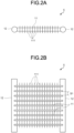
- FIGS. 2A and 2B are diagrams describing the heat exchanger 5 according to this first embodiment, and FIG. 2A illustrates a plan view of the heat exchanger 5 and FIG. 2B illustrate a front view of the heat exchanger 5.
- Flat tubes 11 (first flat tube 11a and second flat tube 11b) each have a flat cross section extending in a direction in which air flows, and a plurality of flow paths through which refrigerant flows is formed inside the flat tubes 11 with being arranged in an air flowing direction.
- the heat exchanger 5 includes a plurality of flat tubes 11 arrayed vertically in such a manner that wide ranging surfaces (wide surfaces) of sides of the flat tubes 11 face, a pair of left and right headers 12 connected to the both ends of the flat tubes 11, and a plurality of fins 111 arranged in a direction intersecting with the flat tubes 11 and bonded with the flat tubes 11.
- a refrigerant pipe through which refrigerant flows is provided on the header 12 for connecting with the other components of the air conditioner 1.
- the flat tubes 11 are arranged vertically in parallel via intervals S1 for letting air through, and the both ends are connected to the pair of headers 12. Specifically, the plurality of flat tubes 11 extending horizontally are arrayed vertically at predetermined intervals S1, and the both ends are connected to the header 12.
- the header 12 has a cylindrical shape. Inside the header 12, refrigerant flow paths (not illustrated) for flowing refrigerant supplied to the heat exchanger 5 to be branched into the plurality of flat tubes 11, and joining refrigerant flowing out from the plurality of flat tubes 11 are formed.
- the fins 111 have a flat plate shape arranged with extending in a direction intersecting with the flat tubes 11 in a front view, and are arrayed horizontally at predetermined array pitches via intervals for letting air through.
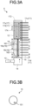
- FIGS. 3A, 3B , 3C, 3D , 3E , 4A, and 4B the header 12 of the heat exchanger 5 according to this first embodiment will be described using FIGS. 3A, 3B , 3C, 3D , 3E , 4A, and 4B .
- the pair of left and right headers 12 are provided. The following description will be given using the left header 12.
- a flat tube 11 side (right side in the drawing) of a lower dividing plate 161 to be described below will be referred to as an internal side, and an opposite side (left side in the drawing) thereof will be referred to as an external side.
- an upper side in the drawing of an upper dividing plate 174 to be described below will be referred to as windward, and an opposite side thereof will be referred to as leeward (lower side in the drawing).
- the fins 111 are omitted.
- a down-pointing arrow in an upper part of a cross-sectional diagram indicates a flowing direction of air.
- FIG. 3A An internal structure of the header 12 will be described using a schematic diagram in FIG. 3A .
- the header 12 is formed into a hollow shape in such a manner that refrigerant is diverged into the plurality of flat tubes 11.
- the header 12 is compartmented into a refrigerant inflow portion 14, a lower circulation portion 16, and an upper circulation portion 17 in order from below.
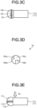
- FIGS. 3B , 3C, 3D, and 3E illustrate cross-sectional diagrams of the header 12 in FIG. 3A viewed from a stack direction of the flat tubes
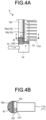
- FIG. 4B illustrates a cross-sectional diagram of the header 12 in FIG. 4A viewed from the stack direction of the flat tubes.
- An inflow tube 13 into which refrigerant flows is connected to the refrigerant inflow portion 14.
- the plurality of flat tubes 11 stacked in a direction vertical to a flow direction of refrigerant flowing in the flat tubes 11 is connected to the header 12 at their one ends, and is classified into a lower flat tube group 11d connected to the lower circulation portion 16, and an upper flat tube group 11u connected to the upper circulation portion 17.
- a plurality of flow path holes (not illustrated) through which refrigerant flows is arranged in parallel to each other from the windward side to the leeward side.
- the refrigerant inflow portion 14 and the lower circulation portion 16 provided above the refrigerant inflow portion 14 are compartmented by an inflow plate 15.
- an ejection hole 151 (orifice) through which refrigerant is ejected from the refrigerant inflow portion 14 toward the lower circulation portion 16 is provided.
- the ejection hole 151 is provided on the leeward side and the internal side of the inflow plate 15, and is located between the lower dividing plate 161 to be described below and one end side of the flat tube 11.
- the ejection hole 151 is arranged at a position not overlapping the one end side of the flat tube 11, it is possible to prevent refrigerant ejected from the ejection hole 151 toward the lower circulation portion 16, from being decelerated by the flat tube 11.
- the lower circulation portion 16 is divided by the lower dividing plate 161 into an ascent path 16i of refrigerant being an internal side (the flat tube 11B side of the lower circulation portion 16), and a descent path 16o of refrigerant being an external side (opposite side of the flat tube 11B side of the lower circulation portion 16).
- the lower dividing plate 161 is arranged with extending downward in the stack direction of flat tubes from a vertical dividing plate 18 to be described below, in such a manner as to divide the lower circulation portion 16 into the internal side and the external side, and the internal side and the external side are connected with each other via the lower accessway 163 at a lower end of the lower dividing plate 161.
- the lower end of the lower dividing plate 161 is located inferiorly to the lowermost flat tube 11 of the lower flat tube group 11d.
- the lower circulation portion 16 and the upper circulation portion 17 provided above the lower circulation portion 16 are compartmented by the vertical dividing plate 18.
- the vertical dividing plate 18 includes a first passing port 18di that lets through refrigerant flowing on the ascent path 16i, toward the upper circulation portion 17, and is provided on the leeward side and the internal side of the header 12, and a first closed portion 18ui that does not let through refrigerant, and is provided on the windward side and the internal side.
- the vertical dividing plate 18 includes a second passing port 18uo that lets through refrigerant from the upper circulation portion 17 toward the lower circulation portion 16, and is provided on the windward side and the external side of the header 12, and a second closed portion 18do that does not let through refrigerant, and is provided on the leeward side and the external side.
- the second closed portion 18do needs not be configured to close a flow path, and may be opened integrally with the second passing port 18uo. Even if the second passing port 18uo is provided only on the windward side and the external side, or even if the second passing port 18uo is provided on the external side from the windward toward the leeward, it is sufficient that the second passing port 18uo can guide refrigerant to the descent path 16o on the external side of the lower circulation portion 16. In short, it is sufficient that the vertical dividing plate 18 includes the second passing port 18uo that lets refrigerant through in a descending direction, at least on the windward external side.
- the upper circulation portion 17 is divided by an upper dividing plate 174 into an ascent path 17d on the leeward side of the header 12, and a descent path 17u on the windward side.
- the upper dividing plate 174 is arranged with extending upward in the stack direction of flat tubes from the above-described vertical dividing plate 18, in such a manner as to divide the upper circulation portion 17 into the windward side and the leeward side.
- the windward side and the leeward side are connected with each other via the upper accessway 172 at an upper end of the upper dividing plate 174.
- a recessed portion is provided at a point corresponding to the upper flat tube group 11u, and the flat tube 11 is inserted thereinto.
- the upper end of the upper dividing plate 174 is located superiorly to the uppermost flat tube 11 of the upper flat tube group 11u.
- FIG. 3A illustrates an example in which the lower flat tube group 11d and the upper flat tube group 11u each include seven flat tubes 11, but the number of flat tubes 11 in each flat tube group is not limited to this.
- the number of flat tubes 11 needs not be the same number between flat tube groups provided across the vertical dividing plate 18.
- cross-sectional areas of the ascent path 16i, the descent path 16o, the ascent path 17d, and the descent path 17u are preliminarily designed in accordance with the state and type of flowing refrigerant. These items can be appropriately set in accordance with demanded performance of the heat exchanger 5.
- refrigerant is diverged into the flat tubes 11 of the lower flat tube group 11d and the upper flat tube group 11u.
- refrigerant is initially ejected from the refrigerant inflow portion 14 toward the ascent path 16i on the internal side of the lower circulation portion 16 via the ejection hole 151 of the inflow plate 15. After that, refrigerant is guided to the ascent path 17d on the leeward side of the upper circulation portion 17 via the first passing port 18di of the vertical dividing plate 18.
- refrigerant turns around at the upper accessway 172, and as indicated by a broken like arrow in FIG. 3A , returns to the descent path 17u on the windward side of the upper circulation portion 17.
- refrigerant is guided to the descent path 16o on the external side of the lower circulation portion 16 via the second passing port 18uo of the vertical dividing plate 18.
- the second passing port 18uo of the vertical dividing plate 18 may be provided only on the windward side and the external side of the header 12, or may be provided on the external side from the windward side toward the leeward side. In short, it is sufficient that the second passing port 18uo can guide refrigerant to the descent path 16o on the external side of the lower circulation portion 16.
- Refrigerant guided to the descent path 16o on the external side of the lower circulation portion 16 turns around at the lower accessway 163, and circulates again to the ascent path 16i on the internal side of the lower circulation portion 16.
- Refrigerant joins refrigerant flowing into the lower circulation portion 16 via the ejection hole 151 of the inflow plate 15, and is diverged into the flat tubes 11.
- areas of the ejection hole 151, the first passing port 18di, and the second passing port 18uo can be appropriately set in accordance with demanded performance of the heat exchanger 5.
- a circulation route from the ascent path 17d on the leeward side toward the descent path 17u on the windward side is formed, and a rate of liquid refrigerant increases on the descent path 17u side being a return pace.
- liquid refrigerant R (indicated by hatching in FIGS. 4A and 4B ) retained on the descent path 16o being a return space of the circulation route of the lower circulation portion 16 will be described using FIGS. 4A and 4B .
- the descent path 16o of the lower circulation portion 16 is an external side space to which the flat tubes 11 are not connected, and the retained liquid refrigerant R does not drift to the flat tubes 11.
- the liquid refrigerant R is prevented from moving toward the ascent path 16i.
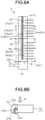
- FIGS. 8A, 8B , 8C, 8D, and 8E illustrate cross-sectional diagrams of the header 12 in FIG. 8A viewed from a stack direction of the flat tubes.
- a header 22 will be described below.
- the second embodiment is similar to the first embodiment in that the description will be given using a left header 22 of a pair of left and right headers 22, and with respect to the header 22, a flat tube 11 side (right side in the drawing) within the header 22 that is compartmented by a lower dividing plate 261 to be described below will be referred to as an internal side, and an opposite side (left side in the drawing) thereof will be referred to as an external side, and an upper side in the drawing of an upper dividing plate 274 to be described below will be referred to as windward, and an opposite side thereof will be referred to as leeward (lower side in the drawing), and the fins 111 are omitted in FIG. 8A .
- the second embodiment aims to enable flow divergence of liquid refrigerant to be appropriately performed in the descent path 17u (space in which refrigerant returns to a lower part) of the upper circulation portion 17 in the first embodiment in a situation in which a circulation amount of refrigerant is large.
- the header 22 includes the upper dividing plate 274 provided in an upper circulation portion 27.
- the upper dividing plate 274 has an L-shaped cross-sectional shape when viewed in a cross section vertical to the stack direction of flat tubes as illustrated in FIG. 8B .
- the upper dividing plate 274 is formed by combining a first dividing portion 274x dividing the internal side of the upper circulation portion 27 into the windward side and the leeward side, and a second dividing portion 274y dividing the leeward side of the header 22 into the external side and the internal side.
- the first dividing portion 274x is provided up to a position inferior to at least the uppermost flat tube of the upper flat tube group 11u, and an upper accessway 272 is provided between an upper end of the upper circulation portion 27.
- a recessed portion is provided at a point corresponding to the upper flat tube group 11u, and the flat tube 11 is inserted thereinto.
- the upper circulation portion 27 is divided into an ascent path 27di of refrigerant on the leeward side and the internal side, a descent path 27u of refrigerant on the windward side, and a descent path 27do of refrigerant on the leeward external side.
- the descent path 27u and the descent path 27do are formed as an integrated space.
- the upper circulation portion 27 is divided in such a manner that the leeward side and the internal side corresponding to a partial space on the leeward side of the upper circulation portion 27 is divided into the ascent path 27di, and a space obtained by adding a partial space on the leeward side and the external side to all spaces on the windward side is divided into the descent paths 27u and 27do.
- the upper dividing plate 174 or 274 divides the upper circulation portion 17 or 27 excluding the upper accessway 172 or 272, into the ascent path 17d or 27di provided on at least part of the leeward side, and the descent path 17u, or 27u/27do provided at least on the windward side.
- refrigerant is diverged into the flat tubes 11 of the lower flat tube group 11d and the upper flat tube group 11u.
- refrigerant is initially ejected from a refrigerant inflow portion 24 toward an ascent path 26i on the internal side of a lower circulation portion 26 via an ejection hole 251 on the leeward side and internal side of an inflow plate 25.
- refrigerant is guided to the ascent path 27di on the leeward side and internal side of the upper circulation portion 27 via the first passing port 28di of the vertical dividing plate 28. Note that FIG.
- FIG. 8C illustrates an example in which another ejection hole 252 is provided on the windward side and the internal side of the inflow plate 25, but this not indispensable as the second embodiment, and it is sufficient that the ejection hole 252 is provided only in a case where ejection of refrigerant to the lower circulation portion 26 needs to be promoted.
- refrigerant turns around at the upper accessway 272, and returns to the descent path 27u on the windward side of the upper circulation portion 27 and the descent path 27do of the leeward external side.
- refrigerant is guided to the descent path 26o on the external side of the lower circulation portion 26 via the second passing port 28uo of the vertical dividing plate 28.
- the second passing port 28uo of the vertical dividing plate 28 may be provided only on the windward external side, or may be provided on the external side from the windward side toward the leeward side. In short, it is sufficient that the second passing port 28uo can guide refrigerant to the descent path 26o on the external side of the lower circulation portion 26.
- Refrigerant guided to the descent path 26o on the external side of the lower circulation portion 26 turns around at the lower accessway 263, and circulates again to the ascent path 26i on the internal side of the lower circulation portion 26.
- the first embodiment can uniformize flow divergence of refrigerant to each flat tube 11, improve non-uniformity of the state of the refrigerant between the windward side and the leeward side in the flat tube 11, and suppresses drift of liquid refrigerant retained in the descent path 16o (return space of refrigerant) of the lower circulation portion 16, to the flat tube 11.
- the second embodiment can suppress influence of retention of liquid refrigerant, and further improve drift in the height direction.
Landscapes
- Engineering & Computer Science (AREA)
- Physics & Mathematics (AREA)
- Thermal Sciences (AREA)
- Mechanical Engineering (AREA)
- General Engineering & Computer Science (AREA)
- Geometry (AREA)
- Heat-Exchange Devices With Radiators And Conduit Assemblies (AREA)
- Details Of Heat-Exchange And Heat-Transfer (AREA)
Claims (4)
- Wärmetauscher (5), der Folgendes aufweist:eine Vielzahl von flachen Rohren (11), die in einer Richtung senkrecht zu einer Strömungsrichtung eines in ihnen strömenden Kältemittels gestapelt sind;einen Sammler (12), mit dem die Vielzahl von flachen Rohren (11) an einem Ende verbunden ist;eine Einströmungsplatte (15), die einen Kältemitteleinströmungsabschnitt (14) und einen unteren Zirkulationsabschnitt (16) trennt, der oberhalb des Kältemitteleinströmungsabschnitts (14) in dem Sammler (12) vorgesehen ist;eine untere Trennplatte (161), die parallel zu einer Stapelrichtung der Vielzahl von flachen Rohren (11) angeordnet ist, um den unteren Zirkulationsabschnitt (16) in einen unteren Aufstiegsweg (16i) auf einer inneren Seite und einen unteren Abstiegsweg (16o) auf einer äußeren Seite zu trennen;einen unteren Zugangsweg (163), der den unteren Aufstiegsweg (16i) und den unteren Abstiegsweg (16o) des unteren Zirkulationsabschnitts (16) zwischen der Einströmungsplatte (15) und der unteren Trennplatte (161) verbindet;wobei die Einströmungsplatte (15) ein Ausstoßloch aufweist, das Kältemittel ausstößt, auf einer leeseitigen Seite und einer inneren Seite,der Wärmetauscher dadurch gekennzeichnet ist, dasser des Weiteren eine senkrechte Trennplatte (174), die den unteren Zirkulationsabschnitt und einen oberen Zirkulationsabschnitt trennt, der oberhalb des unteren Zirkulationsabschnitts in dem Sammler vorgesehen ist; eine obere Trennplatte (172), die sich parallel zu der Stapelrichtung der Vielzahl von flachen Rohren erstreckt, in einem Aufstiegsweg, der auf zumindest einem Teil einer leeseitigen Seite vorgesehen ist, und einem Abstiegsweg, der auf zumindest einer luvseitigen Seite des oberen Zirkulationswegs vorgesehen ist; einen Zugangsweg aufweist, der den Aufstiegsweg und den Abstiegsweg des oberen Zirkulationsabschnitts verbindet; und darin, dassdie senkrechte Trennplatte (18) eine erste Durchlassöffnung, die Kältemittel auf einer leeseitigen Seite und einer inneren Seite durchlässt, und eine zweite Durchlassöffnung aufweist, die Kältemittel zumindest auf einer luvseitigen äußeren Seite durchlässt.
- Wärmetauscher (5) nach Anspruch 1, wobei das Ausstoßloch der Einströmungsplatte (15) in einer Querschnittsansicht zwischen der unteren Trennplatte (161) und einer Seite der Vielzahl von flachen Rohren (11) angeordnet ist.
- Wärmetauscher (5) nach Anspruch 1, wobei ein unteres Ende der unteren Trennplatte (161) des unteren Zirkulationsabschnitts (16) tieferstehend zu einem untersten flachen Rohr der Vielzahl von flachen Rohren (11) angeordnet ist.
- Wärmetauscher (5) nach Anspruch 1, wobei die obere Trennplatte (174) durch einen ersten Trennabschnitt (274x), der eine innere Seite des oberen Zirkulationsabschnitts (27) in Luv und Lee trennt, und einen zweiten Trennabschnitt (274y) ausgebildet ist, der eine leewärtige Seite des oberen Zirkulationsabschnitts (27) in eine äußere Seite und eine innere Seite trennt, derart, dass ein Querschnitt eine L-Form annimmt, und der obere Aufstiegsweg (27di) auf einer leewärtigen Seite und einer inneren Seite angeordnet ist, und der obere Abstiegsweg (27u, 27do) auf einer luvwärtigen Seite oder einer leewärtigen äußeren Seite angeordnet ist.
Applications Claiming Priority (2)
| Application Number | Priority Date | Filing Date | Title |
|---|---|---|---|
| JP2019065435A JP6693588B1 (ja) | 2019-03-29 | 2019-03-29 | 熱交換器 |
| PCT/JP2020/003636 WO2020202759A1 (ja) | 2019-03-29 | 2020-01-31 | 熱交換器 |
Publications (3)
| Publication Number | Publication Date |
|---|---|
| EP3951286A1 EP3951286A1 (de) | 2022-02-09 |
| EP3951286A4 EP3951286A4 (de) | 2022-12-28 |
| EP3951286B1 true EP3951286B1 (de) | 2023-08-09 |
Family
ID=70549773
Family Applications (1)
| Application Number | Title | Priority Date | Filing Date |
|---|---|---|---|
| EP20783711.3A Active EP3951286B1 (de) | 2019-03-29 | 2020-01-31 | Wärmetauscher |
Country Status (6)
| Country | Link |
|---|---|
| US (1) | US11846472B2 (de) |
| EP (1) | EP3951286B1 (de) |
| JP (1) | JP6693588B1 (de) |
| CN (1) | CN113661367B (de) |
| AU (1) | AU2020255434B2 (de) |
| WO (1) | WO2020202759A1 (de) |
Families Citing this family (8)
| Publication number | Priority date | Publication date | Assignee | Title |
|---|---|---|---|---|
| CN112824769B (zh) * | 2019-11-20 | 2025-01-03 | 青岛海信日立空调系统有限公司 | 一种空调器 |
| JP6915714B1 (ja) * | 2020-03-10 | 2021-08-04 | 株式会社富士通ゼネラル | 熱交換器 |
| JP7036166B2 (ja) * | 2020-08-03 | 2022-03-15 | 株式会社富士通ゼネラル | 熱交換器 |
| JP7214042B1 (ja) * | 2021-04-06 | 2023-01-27 | 三菱電機株式会社 | 熱交換器及び空気調和装置 |
| JPWO2024241381A1 (de) * | 2023-05-19 | 2024-11-28 | ||
| CN116294309B (zh) * | 2023-05-23 | 2023-08-15 | 江苏炳凯富汽车零部件制造有限公司 | 一种汽车空调冷凝器的集流管机构 |
| WO2025203542A1 (ja) * | 2024-03-29 | 2025-10-02 | 三菱電機株式会社 | 熱交換器、および冷凍サイクル装置 |
| WO2025203543A1 (ja) * | 2024-03-29 | 2025-10-02 | 三菱電機株式会社 | 熱交換器、および冷凍サイクル装置 |
Family Cites Families (19)
| Publication number | Priority date | Publication date | Assignee | Title |
|---|---|---|---|---|
| DE19918616C2 (de) * | 1998-10-27 | 2001-10-31 | Valeo Klimatechnik Gmbh | Verflüssiger zum Kondensieren des inneren Kältemittels einer Kraftfahrzeugklimatisierung |
| DE10158436A1 (de) | 2001-11-29 | 2003-06-12 | Behr Gmbh & Co | Wärmetauscher |
| JP4055449B2 (ja) | 2002-03-27 | 2008-03-05 | 三菱電機株式会社 | 熱交換器およびこれを用いた空気調和機 |
| JP2010151381A (ja) * | 2008-12-25 | 2010-07-08 | Calsonic Kansei Corp | 蒸発器 |
| CN202041023U (zh) * | 2011-04-24 | 2011-11-16 | 广州大学 | 一种空调表冷器 |
| CN102278908B (zh) * | 2011-09-16 | 2013-06-26 | 四川长虹空调有限公司 | 微通道换热器 |
| JP5761252B2 (ja) | 2013-05-22 | 2015-08-12 | ダイキン工業株式会社 | 熱交換器 |
| JP5741658B2 (ja) | 2013-09-11 | 2015-07-01 | ダイキン工業株式会社 | 熱交換器及び空気調和機 |
| JP5754490B2 (ja) | 2013-09-30 | 2015-07-29 | ダイキン工業株式会社 | 熱交換器および空気調和装置 |
| JP5741680B1 (ja) | 2013-12-27 | 2015-07-01 | ダイキン工業株式会社 | 熱交換器および空気調和装置 |
| JP5794293B2 (ja) | 2013-12-27 | 2015-10-14 | ダイキン工業株式会社 | 熱交換器および空気調和装置 |
| JP6446990B2 (ja) * | 2014-10-16 | 2019-01-09 | ダイキン工業株式会社 | 冷媒分流器 |
| CN105157441B (zh) | 2015-06-17 | 2017-08-01 | 广东工业大学 | 多管排一体式联箱自动调节分液冷凝器 |
| CN106556184B (zh) * | 2015-09-28 | 2019-07-30 | 曼德电子电器有限公司 | 蒸发器和空调系统 |
| JP6202451B2 (ja) * | 2016-02-29 | 2017-09-27 | 三菱重工業株式会社 | 熱交換器及び空気調和機 |
| JP6583141B2 (ja) * | 2016-05-24 | 2019-10-02 | 日本軽金属株式会社 | パラレルフロー型熱交換器 |
| CN110462332B (zh) | 2017-03-27 | 2020-07-10 | 大金工业株式会社 | 热交换器和空调装置 |
| JP7102686B2 (ja) * | 2017-05-19 | 2022-07-20 | 株式会社富士通ゼネラル | 熱交換器 |
| JP7108177B2 (ja) * | 2018-03-30 | 2022-07-28 | ダイキン工業株式会社 | 熱交換器および空気調和装置 |
-
2019
- 2019-03-29 JP JP2019065435A patent/JP6693588B1/ja active Active
-
2020
- 2020-01-31 AU AU2020255434A patent/AU2020255434B2/en active Active
- 2020-01-31 WO PCT/JP2020/003636 patent/WO2020202759A1/ja not_active Ceased
- 2020-01-31 EP EP20783711.3A patent/EP3951286B1/de active Active
- 2020-01-31 US US17/598,673 patent/US11846472B2/en active Active
- 2020-01-31 CN CN202080026053.4A patent/CN113661367B/zh active Active
Also Published As
| Publication number | Publication date |
|---|---|
| JP2020165570A (ja) | 2020-10-08 |
| JP6693588B1 (ja) | 2020-05-13 |
| CN113661367B (zh) | 2022-09-09 |
| CN113661367A (zh) | 2021-11-16 |
| US11846472B2 (en) | 2023-12-19 |
| EP3951286A4 (de) | 2022-12-28 |
| AU2020255434A1 (en) | 2021-10-21 |
| US20220196335A1 (en) | 2022-06-23 |
| EP3951286A1 (de) | 2022-02-09 |
| WO2020202759A1 (ja) | 2020-10-08 |
| AU2020255434B2 (en) | 2022-09-15 |
Similar Documents
| Publication | Publication Date | Title |
|---|---|---|
| EP3951286B1 (de) | Wärmetauscher | |
| US11236954B2 (en) | Heat exchanger and air-conditioner | |
| EP4119867B1 (de) | Wärmetauscher | |
| JP6419882B2 (ja) | 空気調和機 | |
| CN115280091B (zh) | 换热器 | |
| WO2018181828A1 (ja) | 熱交換器 | |
| EP3521747B1 (de) | Wärmetauscher und klimaanlage | |
| EP2930454B1 (de) | Wärmetauscher | |
| KR20220041165A (ko) | 열교환기 및 냉동 사이클 장치 | |
| JP5716496B2 (ja) | 熱交換器および空気調和機 | |
| US20160370119A1 (en) | Heat exchanger assembly having a refrigerant distribution control using selective tube port closures | |
| JP6617003B2 (ja) | 熱交換器 | |
| JP7327214B2 (ja) | 熱交換器 | |
| JP6816411B2 (ja) | 熱交換器 | |
| JP7310655B2 (ja) | 熱交換器 | |
| JP2020085285A (ja) | 熱交換器 | |
| JP2021139530A (ja) | 熱交換器 | |
| JP2018105606A (ja) | 熱交換器及び空気調和機 | |
| JP2018119747A (ja) | エバポレータ |
Legal Events
| Date | Code | Title | Description |
|---|---|---|---|
| STAA | Information on the status of an ep patent application or granted ep patent |
Free format text: STATUS: THE INTERNATIONAL PUBLICATION HAS BEEN MADE |
|
| PUAI | Public reference made under article 153(3) epc to a published international application that has entered the european phase |
Free format text: ORIGINAL CODE: 0009012 |
|
| STAA | Information on the status of an ep patent application or granted ep patent |
Free format text: STATUS: REQUEST FOR EXAMINATION WAS MADE |
|
| 17P | Request for examination filed |
Effective date: 20210928 |
|
| AK | Designated contracting states |
Kind code of ref document: A1 Designated state(s): AL AT BE BG CH CY CZ DE DK EE ES FI FR GB GR HR HU IE IS IT LI LT LU LV MC MK MT NL NO PL PT RO RS SE SI SK SM TR |
|
| DAV | Request for validation of the european patent (deleted) | ||
| DAX | Request for extension of the european patent (deleted) | ||
| A4 | Supplementary search report drawn up and despatched |
Effective date: 20221125 |
|
| RIC1 | Information provided on ipc code assigned before grant |
Ipc: F28F 9/22 20060101ALI20221121BHEP Ipc: F28F 9/02 20060101ALI20221121BHEP Ipc: F28F 1/02 20060101ALI20221121BHEP Ipc: F28D 1/053 20060101ALI20221121BHEP Ipc: F25B 39/00 20060101AFI20221121BHEP |
|
| GRAP | Despatch of communication of intention to grant a patent |
Free format text: ORIGINAL CODE: EPIDOSNIGR1 |
|
| STAA | Information on the status of an ep patent application or granted ep patent |
Free format text: STATUS: GRANT OF PATENT IS INTENDED |
|
| INTG | Intention to grant announced |
Effective date: 20230223 |
|
| GRAS | Grant fee paid |
Free format text: ORIGINAL CODE: EPIDOSNIGR3 |
|
| GRAA | (expected) grant |
Free format text: ORIGINAL CODE: 0009210 |
|
| STAA | Information on the status of an ep patent application or granted ep patent |
Free format text: STATUS: THE PATENT HAS BEEN GRANTED |
|
| AK | Designated contracting states |
Kind code of ref document: B1 Designated state(s): AL AT BE BG CH CY CZ DE DK EE ES FI FR GB GR HR HU IE IS IT LI LT LU LV MC MK MT NL NO PL PT RO RS SE SI SK SM TR |
|
| REG | Reference to a national code |
Ref country code: GB Ref legal event code: FG4D |
|
| REG | Reference to a national code |
Ref country code: CH Ref legal event code: EP |
|
| REG | Reference to a national code |
Ref country code: IE Ref legal event code: FG4D |
|
| REG | Reference to a national code |
Ref country code: DE Ref legal event code: R096 Ref document number: 602020015561 Country of ref document: DE |
|
| REG | Reference to a national code |
Ref country code: LT Ref legal event code: MG9D |
|
| REG | Reference to a national code |
Ref country code: NL Ref legal event code: MP Effective date: 20230809 |
|
| REG | Reference to a national code |
Ref country code: AT Ref legal event code: MK05 Ref document number: 1597955 Country of ref document: AT Kind code of ref document: T Effective date: 20230809 |
|
| PG25 | Lapsed in a contracting state [announced via postgrant information from national office to epo] |
Ref country code: GR Free format text: LAPSE BECAUSE OF FAILURE TO SUBMIT A TRANSLATION OF THE DESCRIPTION OR TO PAY THE FEE WITHIN THE PRESCRIBED TIME-LIMIT Effective date: 20231110 |
|
| PG25 | Lapsed in a contracting state [announced via postgrant information from national office to epo] |
Ref country code: IS Free format text: LAPSE BECAUSE OF FAILURE TO SUBMIT A TRANSLATION OF THE DESCRIPTION OR TO PAY THE FEE WITHIN THE PRESCRIBED TIME-LIMIT Effective date: 20231209 |
|
| PG25 | Lapsed in a contracting state [announced via postgrant information from national office to epo] |
Ref country code: SE Free format text: LAPSE BECAUSE OF FAILURE TO SUBMIT A TRANSLATION OF THE DESCRIPTION OR TO PAY THE FEE WITHIN THE PRESCRIBED TIME-LIMIT Effective date: 20230809 Ref country code: RS Free format text: LAPSE BECAUSE OF FAILURE TO SUBMIT A TRANSLATION OF THE DESCRIPTION OR TO PAY THE FEE WITHIN THE PRESCRIBED TIME-LIMIT Effective date: 20230809 Ref country code: PT Free format text: LAPSE BECAUSE OF FAILURE TO SUBMIT A TRANSLATION OF THE DESCRIPTION OR TO PAY THE FEE WITHIN THE PRESCRIBED TIME-LIMIT Effective date: 20231211 Ref country code: NO Free format text: LAPSE BECAUSE OF FAILURE TO SUBMIT A TRANSLATION OF THE DESCRIPTION OR TO PAY THE FEE WITHIN THE PRESCRIBED TIME-LIMIT Effective date: 20231109 Ref country code: NL Free format text: LAPSE BECAUSE OF FAILURE TO SUBMIT A TRANSLATION OF THE DESCRIPTION OR TO PAY THE FEE WITHIN THE PRESCRIBED TIME-LIMIT Effective date: 20230809 Ref country code: LV Free format text: LAPSE BECAUSE OF FAILURE TO SUBMIT A TRANSLATION OF THE DESCRIPTION OR TO PAY THE FEE WITHIN THE PRESCRIBED TIME-LIMIT Effective date: 20230809 Ref country code: LT Free format text: LAPSE BECAUSE OF FAILURE TO SUBMIT A TRANSLATION OF THE DESCRIPTION OR TO PAY THE FEE WITHIN THE PRESCRIBED TIME-LIMIT Effective date: 20230809 Ref country code: IS Free format text: LAPSE BECAUSE OF FAILURE TO SUBMIT A TRANSLATION OF THE DESCRIPTION OR TO PAY THE FEE WITHIN THE PRESCRIBED TIME-LIMIT Effective date: 20231209 Ref country code: HR Free format text: LAPSE BECAUSE OF FAILURE TO SUBMIT A TRANSLATION OF THE DESCRIPTION OR TO PAY THE FEE WITHIN THE PRESCRIBED TIME-LIMIT Effective date: 20230809 Ref country code: GR Free format text: LAPSE BECAUSE OF FAILURE TO SUBMIT A TRANSLATION OF THE DESCRIPTION OR TO PAY THE FEE WITHIN THE PRESCRIBED TIME-LIMIT Effective date: 20231110 Ref country code: FI Free format text: LAPSE BECAUSE OF FAILURE TO SUBMIT A TRANSLATION OF THE DESCRIPTION OR TO PAY THE FEE WITHIN THE PRESCRIBED TIME-LIMIT Effective date: 20230809 Ref country code: AT Free format text: LAPSE BECAUSE OF FAILURE TO SUBMIT A TRANSLATION OF THE DESCRIPTION OR TO PAY THE FEE WITHIN THE PRESCRIBED TIME-LIMIT Effective date: 20230809 |
|
| PG25 | Lapsed in a contracting state [announced via postgrant information from national office to epo] |
Ref country code: PL Free format text: LAPSE BECAUSE OF FAILURE TO SUBMIT A TRANSLATION OF THE DESCRIPTION OR TO PAY THE FEE WITHIN THE PRESCRIBED TIME-LIMIT Effective date: 20230809 |
|
| PG25 | Lapsed in a contracting state [announced via postgrant information from national office to epo] |
Ref country code: ES Free format text: LAPSE BECAUSE OF FAILURE TO SUBMIT A TRANSLATION OF THE DESCRIPTION OR TO PAY THE FEE WITHIN THE PRESCRIBED TIME-LIMIT Effective date: 20230809 |
|
| PG25 | Lapsed in a contracting state [announced via postgrant information from national office to epo] |
Ref country code: SM Free format text: LAPSE BECAUSE OF FAILURE TO SUBMIT A TRANSLATION OF THE DESCRIPTION OR TO PAY THE FEE WITHIN THE PRESCRIBED TIME-LIMIT Effective date: 20230809 Ref country code: RO Free format text: LAPSE BECAUSE OF FAILURE TO SUBMIT A TRANSLATION OF THE DESCRIPTION OR TO PAY THE FEE WITHIN THE PRESCRIBED TIME-LIMIT Effective date: 20230809 Ref country code: ES Free format text: LAPSE BECAUSE OF FAILURE TO SUBMIT A TRANSLATION OF THE DESCRIPTION OR TO PAY THE FEE WITHIN THE PRESCRIBED TIME-LIMIT Effective date: 20230809 Ref country code: EE Free format text: LAPSE BECAUSE OF FAILURE TO SUBMIT A TRANSLATION OF THE DESCRIPTION OR TO PAY THE FEE WITHIN THE PRESCRIBED TIME-LIMIT Effective date: 20230809 Ref country code: DK Free format text: LAPSE BECAUSE OF FAILURE TO SUBMIT A TRANSLATION OF THE DESCRIPTION OR TO PAY THE FEE WITHIN THE PRESCRIBED TIME-LIMIT Effective date: 20230809 Ref country code: CZ Free format text: LAPSE BECAUSE OF FAILURE TO SUBMIT A TRANSLATION OF THE DESCRIPTION OR TO PAY THE FEE WITHIN THE PRESCRIBED TIME-LIMIT Effective date: 20230809 Ref country code: SK Free format text: LAPSE BECAUSE OF FAILURE TO SUBMIT A TRANSLATION OF THE DESCRIPTION OR TO PAY THE FEE WITHIN THE PRESCRIBED TIME-LIMIT Effective date: 20230809 |
|
| REG | Reference to a national code |
Ref country code: DE Ref legal event code: R097 Ref document number: 602020015561 Country of ref document: DE |
|
| PG25 | Lapsed in a contracting state [announced via postgrant information from national office to epo] |
Ref country code: IT Free format text: LAPSE BECAUSE OF FAILURE TO SUBMIT A TRANSLATION OF THE DESCRIPTION OR TO PAY THE FEE WITHIN THE PRESCRIBED TIME-LIMIT Effective date: 20230809 |
|
| PLBE | No opposition filed within time limit |
Free format text: ORIGINAL CODE: 0009261 |
|
| STAA | Information on the status of an ep patent application or granted ep patent |
Free format text: STATUS: NO OPPOSITION FILED WITHIN TIME LIMIT |
|
| 26N | No opposition filed |
Effective date: 20240513 |
|
| PG25 | Lapsed in a contracting state [announced via postgrant information from national office to epo] |
Ref country code: SI Free format text: LAPSE BECAUSE OF FAILURE TO SUBMIT A TRANSLATION OF THE DESCRIPTION OR TO PAY THE FEE WITHIN THE PRESCRIBED TIME-LIMIT Effective date: 20230809 |
|
| PG25 | Lapsed in a contracting state [announced via postgrant information from national office to epo] |
Ref country code: MC Free format text: LAPSE BECAUSE OF FAILURE TO SUBMIT A TRANSLATION OF THE DESCRIPTION OR TO PAY THE FEE WITHIN THE PRESCRIBED TIME-LIMIT Effective date: 20230809 |
|
| PG25 | Lapsed in a contracting state [announced via postgrant information from national office to epo] |
Ref country code: MC Free format text: LAPSE BECAUSE OF FAILURE TO SUBMIT A TRANSLATION OF THE DESCRIPTION OR TO PAY THE FEE WITHIN THE PRESCRIBED TIME-LIMIT Effective date: 20230809 |
|
| REG | Reference to a national code |
Ref country code: CH Ref legal event code: PL |
|
| PG25 | Lapsed in a contracting state [announced via postgrant information from national office to epo] |
Ref country code: LU Free format text: LAPSE BECAUSE OF NON-PAYMENT OF DUE FEES Effective date: 20240131 |
|
| PG25 | Lapsed in a contracting state [announced via postgrant information from national office to epo] |
Ref country code: LU Free format text: LAPSE BECAUSE OF NON-PAYMENT OF DUE FEES Effective date: 20240131 |
|
| PG25 | Lapsed in a contracting state [announced via postgrant information from national office to epo] |
Ref country code: BE Free format text: LAPSE BECAUSE OF NON-PAYMENT OF DUE FEES Effective date: 20240131 |
|
| PG25 | Lapsed in a contracting state [announced via postgrant information from national office to epo] |
Ref country code: CH Free format text: LAPSE BECAUSE OF NON-PAYMENT OF DUE FEES Effective date: 20240131 |
|
| PG25 | Lapsed in a contracting state [announced via postgrant information from national office to epo] |
Ref country code: CH Free format text: LAPSE BECAUSE OF NON-PAYMENT OF DUE FEES Effective date: 20240131 Ref country code: BE Free format text: LAPSE BECAUSE OF NON-PAYMENT OF DUE FEES Effective date: 20240131 |
|
| REG | Reference to a national code |
Ref country code: BE Ref legal event code: MM Effective date: 20240131 |
|
| PG25 | Lapsed in a contracting state [announced via postgrant information from national office to epo] |
Ref country code: BG Free format text: LAPSE BECAUSE OF FAILURE TO SUBMIT A TRANSLATION OF THE DESCRIPTION OR TO PAY THE FEE WITHIN THE PRESCRIBED TIME-LIMIT Effective date: 20230809 |
|
| PG25 | Lapsed in a contracting state [announced via postgrant information from national office to epo] |
Ref country code: BG Free format text: LAPSE BECAUSE OF FAILURE TO SUBMIT A TRANSLATION OF THE DESCRIPTION OR TO PAY THE FEE WITHIN THE PRESCRIBED TIME-LIMIT Effective date: 20230809 |
|
| PG25 | Lapsed in a contracting state [announced via postgrant information from national office to epo] |
Ref country code: IE Free format text: LAPSE BECAUSE OF NON-PAYMENT OF DUE FEES Effective date: 20240131 |
|
| PG25 | Lapsed in a contracting state [announced via postgrant information from national office to epo] |
Ref country code: IE Free format text: LAPSE BECAUSE OF NON-PAYMENT OF DUE FEES Effective date: 20240131 |
|
| PG25 | Lapsed in a contracting state [announced via postgrant information from national office to epo] |
Ref country code: CY Free format text: LAPSE BECAUSE OF FAILURE TO SUBMIT A TRANSLATION OF THE DESCRIPTION OR TO PAY THE FEE WITHIN THE PRESCRIBED TIME-LIMIT; INVALID AB INITIO Effective date: 20200131 |
|
| PG25 | Lapsed in a contracting state [announced via postgrant information from national office to epo] |
Ref country code: HU Free format text: LAPSE BECAUSE OF FAILURE TO SUBMIT A TRANSLATION OF THE DESCRIPTION OR TO PAY THE FEE WITHIN THE PRESCRIBED TIME-LIMIT; INVALID AB INITIO Effective date: 20200131 |
|
| PG25 | Lapsed in a contracting state [announced via postgrant information from national office to epo] |
Ref country code: TR Free format text: LAPSE BECAUSE OF FAILURE TO SUBMIT A TRANSLATION OF THE DESCRIPTION OR TO PAY THE FEE WITHIN THE PRESCRIBED TIME-LIMIT Effective date: 20230809 |
|
| PGFP | Annual fee paid to national office [announced via postgrant information from national office to epo] |
Ref country code: GB Payment date: 20260121 Year of fee payment: 7 |
|
| PGFP | Annual fee paid to national office [announced via postgrant information from national office to epo] |
Ref country code: DE Payment date: 20260120 Year of fee payment: 7 |
|
| PGFP | Annual fee paid to national office [announced via postgrant information from national office to epo] |
Ref country code: FR Payment date: 20260121 Year of fee payment: 7 |