EP3951290B1 - Ensemble d'infusion pour réfrigérateur - Google Patents
Ensemble d'infusion pour réfrigérateur Download PDFInfo
- Publication number
- EP3951290B1 EP3951290B1 EP20781793.3A EP20781793A EP3951290B1 EP 3951290 B1 EP3951290 B1 EP 3951290B1 EP 20781793 A EP20781793 A EP 20781793A EP 3951290 B1 EP3951290 B1 EP 3951290B1
- Authority
- EP
- European Patent Office
- Prior art keywords
- water
- assembly
- brewing
- dispensing
- flow
- Prior art date
- Legal status (The legal status is an assumption and is not a legal conclusion. Google has not performed a legal analysis and makes no representation as to the accuracy of the status listed.)
- Active
Links
Images

Classifications
-
- A—HUMAN NECESSITIES
- A47—FURNITURE; DOMESTIC ARTICLES OR APPLIANCES; COFFEE MILLS; SPICE MILLS; SUCTION CLEANERS IN GENERAL
- A47J—KITCHEN EQUIPMENT; COFFEE MILLS; SPICE MILLS; APPARATUS FOR MAKING BEVERAGES
- A47J31/00—Apparatus for making beverages
- A47J31/44—Parts or details or accessories of beverage-making apparatus
- A47J31/46—Dispensing spouts, pumps, drain valves or like liquid transporting devices
- A47J31/462—Dispensing spouts, pumps, drain valves or like liquid transporting devices with an intermediate liquid storage tank
- A47J31/467—Dispensing spouts, pumps, drain valves or like liquid transporting devices with an intermediate liquid storage tank for the infusion
-
- A—HUMAN NECESSITIES
- A47—FURNITURE; DOMESTIC ARTICLES OR APPLIANCES; COFFEE MILLS; SPICE MILLS; SUCTION CLEANERS IN GENERAL
- A47J—KITCHEN EQUIPMENT; COFFEE MILLS; SPICE MILLS; APPARATUS FOR MAKING BEVERAGES
- A47J31/00—Apparatus for making beverages
- A47J31/10—Coffee-making apparatus, in which the brewing vessel, i.e. water heating container, is placed above or in the upper part of the beverage containers i.e. brewing vessel; Drip coffee-makers with the water heating container in a higher position than the brewing vessel
-
- A—HUMAN NECESSITIES
- A47—FURNITURE; DOMESTIC ARTICLES OR APPLIANCES; COFFEE MILLS; SPICE MILLS; SUCTION CLEANERS IN GENERAL
- A47J—KITCHEN EQUIPMENT; COFFEE MILLS; SPICE MILLS; APPARATUS FOR MAKING BEVERAGES
- A47J31/00—Apparatus for making beverages
- A47J31/40—Beverage-making apparatus with dispensing means for adding a measured quantity of ingredients, e.g. coffee, water, sugar, cocoa, milk, tea
- A47J31/407—Beverage-making apparatus with dispensing means for adding a measured quantity of ingredients, e.g. coffee, water, sugar, cocoa, milk, tea with ingredient-containing cartridges; Cartridge-perforating means
-
- A—HUMAN NECESSITIES
- A47—FURNITURE; DOMESTIC ARTICLES OR APPLIANCES; COFFEE MILLS; SPICE MILLS; SUCTION CLEANERS IN GENERAL
- A47J—KITCHEN EQUIPMENT; COFFEE MILLS; SPICE MILLS; APPARATUS FOR MAKING BEVERAGES
- A47J31/00—Apparatus for making beverages
- A47J31/44—Parts or details or accessories of beverage-making apparatus
- A47J31/46—Dispensing spouts, pumps, drain valves or like liquid transporting devices
- A47J31/461—Valves, e.g. drain valves
-
- A—HUMAN NECESSITIES
- A47—FURNITURE; DOMESTIC ARTICLES OR APPLIANCES; COFFEE MILLS; SPICE MILLS; SUCTION CLEANERS IN GENERAL
- A47J—KITCHEN EQUIPMENT; COFFEE MILLS; SPICE MILLS; APPARATUS FOR MAKING BEVERAGES
- A47J31/00—Apparatus for making beverages
- A47J31/44—Parts or details or accessories of beverage-making apparatus
- A47J31/52—Alarm-clock-controlled mechanisms for coffee- or tea-making apparatus ; Timers for coffee- or tea-making apparatus; Electronic control devices for coffee- or tea-making apparatus
- A47J31/525—Alarm-clock-controlled mechanisms for coffee- or tea-making apparatus ; Timers for coffee- or tea-making apparatus; Electronic control devices for coffee- or tea-making apparatus the electronic control being based on monitoring of specific process parameters
-
- F—MECHANICAL ENGINEERING; LIGHTING; HEATING; WEAPONS; BLASTING
- F25—REFRIGERATION OR COOLING; COMBINED HEATING AND REFRIGERATION SYSTEMS; HEAT PUMP SYSTEMS; MANUFACTURE OR STORAGE OF ICE; LIQUEFACTION SOLIDIFICATION OF GASES
- F25D—REFRIGERATORS; COLD ROOMS; ICE-BOXES; COOLING OR FREEZING APPARATUS NOT OTHERWISE PROVIDED FOR
- F25D23/00—General constructional features
- F25D23/12—Arrangements of compartments additional to cooling compartments; Combinations of refrigerators with other equipment, e.g. stove
-
- A—HUMAN NECESSITIES
- A47—FURNITURE; DOMESTIC ARTICLES OR APPLIANCES; COFFEE MILLS; SPICE MILLS; SUCTION CLEANERS IN GENERAL
- A47J—KITCHEN EQUIPMENT; COFFEE MILLS; SPICE MILLS; APPARATUS FOR MAKING BEVERAGES
- A47J31/00—Apparatus for making beverages
- A47J31/02—Coffee-making machines with removable extraction cups, to be placed on top of drinking-vessels i.e. coffee-makers with removable brewing vessels, to be placed on top of beverage containers, into which hot water is poured, e.g. cafe filter
-
- A—HUMAN NECESSITIES
- A47—FURNITURE; DOMESTIC ARTICLES OR APPLIANCES; COFFEE MILLS; SPICE MILLS; SUCTION CLEANERS IN GENERAL
- A47J—KITCHEN EQUIPMENT; COFFEE MILLS; SPICE MILLS; APPARATUS FOR MAKING BEVERAGES
- A47J31/00—Apparatus for making beverages
- A47J31/40—Beverage-making apparatus with dispensing means for adding a measured quantity of ingredients, e.g. coffee, water, sugar, cocoa, milk, tea
-
- F—MECHANICAL ENGINEERING; LIGHTING; HEATING; WEAPONS; BLASTING
- F25—REFRIGERATION OR COOLING; COMBINED HEATING AND REFRIGERATION SYSTEMS; HEAT PUMP SYSTEMS; MANUFACTURE OR STORAGE OF ICE; LIQUEFACTION SOLIDIFICATION OF GASES
- F25D—REFRIGERATORS; COLD ROOMS; ICE-BOXES; COOLING OR FREEZING APPARATUS NOT OTHERWISE PROVIDED FOR
- F25D2331/00—Details or arrangements of other cooling or freezing apparatus not provided for in other groups of this subclass
- F25D2331/80—Type of cooled receptacles
- F25D2331/81—Pitchers
-
- F—MECHANICAL ENGINEERING; LIGHTING; HEATING; WEAPONS; BLASTING
- F25—REFRIGERATION OR COOLING; COMBINED HEATING AND REFRIGERATION SYSTEMS; HEAT PUMP SYSTEMS; MANUFACTURE OR STORAGE OF ICE; LIQUEFACTION SOLIDIFICATION OF GASES
- F25D—REFRIGERATORS; COLD ROOMS; ICE-BOXES; COOLING OR FREEZING APPARATUS NOT OTHERWISE PROVIDED FOR
- F25D2700/00—Means for sensing or measuring; Sensors therefor
- F25D2700/06—Sensors detecting the presence of a product
Definitions
- the present subject matter relates generally to refrigerator appliances, and more particularly to beverage brewing systems and assemblies for refrigerator appliances.
- Typical beverage brewing processes include pouring hot water into beverage contents, e.g., ground coffee or tea leaves, and permitting the hot water to seep through the grounds to create the brewed beverage.
- beverage contents e.g., ground coffee or tea leaves
- hot water e.g., around 93,333 °C, i.e. around 200 °F
- Heated water accelerates the brewing process and allows for heated coffee to be brewed in a matter of minutes.
- Another method of brewing coffee is a cold brew process during which coffee grounds are brewed without hot water.
- such a cold brewing process takes a significantly longer amount of time to brew, e.g., around five to twenty-four hours.
- an improved brewing assembly for cold brew beverages would be useful. More specifically, a cold brew system that facilities a simplified brewing process while maintaining the beverage at a cooled temperature would be particularly beneficial.
- US2018/187964A1 discloses a refrigerator including a body with a storage compartment and a dispenser, a water tank case disposed in the door, a water tank separably mounted in the water tank case, a water level sensor and a water tank valve.
- a refrigerator appliance defining a vertical direction.
- the refrigerator appliance includes a cabinet that defines a chilled chamber for receipt of food articles for storage, a dispensing assembly including an outlet for selectively dispensing a flow of water, and a brewing assembly positionable within the cabinet for receiving the flow of water from the dispensing assembly.
- the brewing assembly includes a pitcher removably positioned within the chilled chamber below the outlet of the dispensing assembly, a brew module positioned within the pitcher and including a plurality canisters for receiving brewing contents and the flow of water from the dispensing assembly to create a brewed beverage, and a lower reservoir positioned below the brew module for receiving the brewed beverage from the one or more canisters.
- a brewing assembly for a refrigerator appliance includes a dispensing assembly for selectively dispensing a flow of water, a pitcher removably positioned within the refrigerator appliance and being fluidly coupled to the dispensing assembly, and an upper reservoir positioned within the pitcher for receiving the flow of water from the dispensing assembly.
- a brew module is positioned within the pitcher below the upper reservoir and includes a plurality of canisters for receiving brewing contents and the flow of water from the upper reservoir to create a brewed beverage and a lower reservoir is positioned below the brew module for receiving the brewed beverage from the plurality of canisters.
- upstream and downstream refer to the relative direction with respect to fluid flow in a fluid pathway. For example, “upstream” refers to the direction from which the fluid flows, and “downstream” refers to the direction to which the fluid flows.
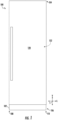
- FIG. 1 provides a front view of a refrigerator appliance 100 according to an exemplary embodiment of the present subject matter.
- refrigerator appliance 100 is a built-in or column refrigerator appliance configured to be built into a wall or cabinetry.
- inventive aspects of the present disclosure apply to other types and styles of refrigerator appliances, such as e.g., bottom mount refrigerator appliances, top mount refrigerator appliances, side-by-side refrigerator appliances, etc. Consequently, the description set forth herein is for illustrative purposes only and is not intended to be limiting in any aspect to any particular refrigerator appliance type or configuration.
- Refrigerator appliance 100 includes a cabinet or housing 102 that extends between a top 104 and a bottom 106 along a vertical direction V, between a first side 108 and a second side 110 along a lateral direction L, and between a front side and a rear side along a transverse direction T (a direction extending into and out of the page in FIG 1 ).
- Each of the vertical direction V, lateral direction L, and transverse direction T are mutually perpendicular to one another and form an orthogonal direction system.
- Housing 102 includes an insulated liner 120 which at least partially defines a chilled chamber for receipt of food items for storage.
- housing 102 and/or liner 120 defines a fresh food chamber 122.
- column refrigerator appliance 100 is a single purpose unit in this example embodiment.
- Refrigerator door 128 is rotatably mounted to an edge of housing 102 for selectively accessing fresh food chamber 122. Refrigerator door 128 is shown in the closed configuration in FIG. 1 .
- FIG. 1 One skilled in the art will appreciate that other chamber and door configurations are possible and within the scope of the present invention.
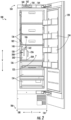
- FIG. 2 provides a front view of refrigerator appliance 100 shown with refrigerator door 128 in the open position.
- various storage components are mounted within fresh food chamber 122 to facilitate storage of food items therein as will be understood by those skilled in the art.
- the storage components may include bins 134 and shelves 136. Each of these storage components are configured for receipt of food items (e.g., beverages and/or solid food items) and may assist with organizing such food items.
- bins 134 may be mounted on refrigerator door 128 or may slide into a receiving space in fresh food chamber 122. It should be appreciated that the illustrated storage components are used only for the purpose of explanation and that other storage components may be used and may have different sizes, shapes, and configurations.
- Dispensing assembly 140 is generally configured for dispensing liquid water for consumption and/or to facilitate a cold brew process as described below. Although an exemplary dispensing assembly 140 is illustrated and described herein, it should be appreciated that variations and modifications may be made to dispensing assembly 140 while remaining within the present subject matter.
- dispensing assembly 140 and its various components may be positioned within fresh food chamber 122.
- dispenser assembly 140 may be positioned on a front side of refrigerator appliance 100 (e.g., on refrigerator door 128) such that a user may operate dispensing assembly 140 without opening refrigerator door 128.
- dispensing assembly 140 includes a water outlet 142 for selectively dispensing the flow of water (e.g. identified herein by reference numeral 144).
- Dispensing assembly 140 may further include an actuation mechanism 146, shown as a push button, for selectively dispensing the flow of water 144 or initiating a cold brew process.
- any suitable actuating mechanism may be used to operate dispensing assembly 140, such as an ultrasonic sensor that detects the presence of a container, a paddle, an input on a refrigerator control panel, etc.
- Refrigerator appliance 100 includes a control panel 160.
- Control panel 160 includes one or more input selectors 162, such as e.g., knobs, buttons, push buttons, touchscreen interfaces, etc.
- input selectors 162 may be used to specify or set various settings of refrigerator appliance 100, such as e.g., settings associated with a cold brew coffee system as will be explained further below.
- Input selectors 162 may be in communication with a processing device or controller 164. Control signals generated in or by controller 164 operate refrigerator appliance 100 in response to input selectors 162.
- control panel 160 may include a display 166, such as an indicator light or a screen. Display 166 is communicatively coupled with controller 164 and may display information in response to signals from controller 164. Further, as will be described herein, controller 164 may be communicatively coupled with other components of refrigerator appliance 100, such as e.g., one or more sensors and components of a cold brew coffee system.
- processing device or “controller” may refer to one or more microprocessors or semiconductor devices and is not restricted necessarily to a single element.
- the processing device can be programmed to operate refrigerator appliance 100.
- the processing device may include, or be associated with, one or more memory elements (e.g., non-transitory storage media).
- the memory elements include electrically erasable, programmable read only memory (EEPROM).
- EEPROM electrically erasable, programmable read only memory
- the memory elements can store information accessible processing device, including instructions that can be executed by processing device.
- the instructions can be software or any set of instructions and/or data that when executed by the processing device, cause the processing device to perform operations.
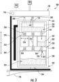
- refrigerator appliance 100 includes a brewing assembly 200 disposed within fresh food chamber 122.
- brewing assembly 200 is configured to cold brew a beverage within refrigerator appliance 100.
- the embodiment described herein describes brewing assembly 100 as being used to make cold brew coffee using coffee grounds.
- brewing assembly 200 may use any other type of brewing contents to brew any other brewed beverage, e.g., such as tea leaves to make cold brew tea.
- brewing assembly 200 includes a pitcher 202 which is removably positioned within the fresh food chamber 122 within pitcher housing 204.
- pitcher housing 204 may be a bracket or receptacle fixed within fresh food chamber 122 for removably receiving pitcher 202 and securing it in place during a brewing process.
- pitcher housing 204 may be configured for placing pitcher 202 fluid communication with dispensing assembly 140 of refrigerator appliance 100.
- controller 164 may operate dispensing assembly 140 perform an autofill process to facilitate the cold brew process. For example, a user may commence the cold brew process by pressing actuation mechanism 146 and dispensing assembly 140 may automatically selectively dispense the flow of water 144 at the desired times and flow rates to facilitate the cold brew process as described below.
- pitcher housing 204 is illustrated herein as being mounted within fresh food chamber 122 and being configured for receiving and supporting pitcher 202, it should be appreciated that according to alternative embodiments, no pitcher housing 204 may be needed at all.
- pitcher 202 may be supported by one of shelves 136 which may have a dedicated spot or recess for receiving pitcher 202.
- another suitable structure such as insulated liner 120 of refrigerator appliance 100 may secure pitcher 202 in position underneath dispensing assembly 140.
- an exemplary brewing assembly 200 is described below, it should be appreciated that variations and modifications may be made to dispensing assembly 140, brewing assembly 200, and other features of refrigerator appliance 100 while remaining within the scope of the present subject matter.
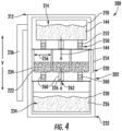
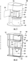
- brewing assembly 200 includes an upper reservoir 210 positioned within pitcher 202 at a top 212 of pitcher 202.
- Upper reservoir 210 generally defines an upper storage volume 214 which is fluidly coupled with outlet 142 of dispensing assembly 140 when pitcher 202 is placed in the installed position within pitcher housing 204.
- upper reservoir 210 is periodically filled with water 144 by dispensing assembly 140 to facilitate the cold brew process.
- Brewing assembly 200 further includes a brew module 220 positioned within pitcher 202 below upper reservoir 210.
- brew module 220 includes one or more canisters 222 for receiving brewing contents (e.g., identified herein by reference numeral 224) and the flow of water 144 selectively dispensed from upper reservoir 210 to create a brewed beverage (e.g., illustrated herein by reference numeral 226).
- the flow of water 144 may seep or pass slowly through brewing contents 224, e.g., coffee grounds, to extract flavor from brewing contents 224 and make the brewed beverage 226.
- brew module 220 is positioned below upper reservoir 210 along the vertical direction V to facilitate a gravity assisted brewing process.
- Brewing assembly 200 further includes a lower reservoir 230 which is positioned below brew module 220 (e.g., at a bottom 232 of pitcher 202) for receiving brewed beverage 226 from canisters 222.
- lower reservoir 230 defines a lower storage volume 234 which is configured for receiving and storing all of brewed beverage 226 after the cold brew process is completed.
- upper storage volume 214 is less than lower storage volume 234.
- dispensing assembly 140 is generally configured for filling upper reservoir 210 two or more times during a brewing process. In this manner, dispensing assembly 140 need not be continuously operated throughout a brewing process, but instead periodically fills upper reservoir 210 which may then selectively dispense the flow of water 144 at a slower rate as described in detail below.
- brewing assembly 200 includes a handle 236 that is mounted to pitcher 202 for removing pitcher 202 altogether from refrigerator appliance 100.
- pitcher 202 may define an outlet conduit (not shown) and an outlet spout (not shown).
- the outlet conduit may extend from lower reservoir 230 to the outlet spout for dispensing brewed beverage 226 for consumption.
- upper reservoir 210, brew module 220, and lower reservoir 230 are substantially self-enclosed such that pitcher 202 does not leak when a user tilts to pour brewed beverage 226.
- brewing assembly 200 may include any other suitable means for pouring or providing access to brewed beverage 226.
- pitcher 202 may include a pivoting access panel (e.g., similar to access panel 270 described below) which a user may open to remove lower reservoir 230 from pitcher 202 after the cold brew process is complete.
- lower reservoir 230 may further include a separate handle (not shown) to facilitate easy pouring of brewed beverage 226.
- upper reservoir 210 is periodically filled by dispensing assembly 140 which then selectively dispenses a flow of water 144 into brew module 220.
- upper reservoir 210 includes a plurality of drip passages 250 which fluidly connect upper storage volume 214 and brew module 220.
- a single drip passage 250 extends substantially along the vertical direction V from upper reservoir 210 to a nozzle positioned immediately above each of canisters 222. In this manner, drip passages 250 may dispense the flow of water 144 directly into each of canisters 222 of brew module 220.
- drip passages 250 are sized so that water 144 drips from upper storage volume 214 into canisters 222 at a desired flow rate.
- brewing assembly 200 includes a plurality of water dispensing valves 252 which are fluidly coupled to upper reservoir 210 for regulating the flow of water 144 through drip passages 250.
- water dispensing valves 252 are fluidly coupled to drip passages 250 for permitting water 144 to drip slowly into canisters 222 during the brewing process, for regulating the residence time of the water within beverage contents 224, or for otherwise regulating the brewing process.
- each of canisters 222 are elongated along the vertical direction V and receive a slow drip of water 144 to achieve a stronger brewed beverage 226.
- each of the canisters 222 may define a height 254 measured along the vertical direction V and an average diameter 256, e.g., measured perpendicular to the vertical direction V.
- height 254 is greater than two times average diameter 256.
- height 254 may be greater than four times average diameter 256 or the ratio of height 254 over average diameter 256 may be even larger, such as 5:1, 10:1, or greater.
- brew module 220 may further include one or more brew valves 260 which are configured for regulating the flow of brewed beverage 226 from brew module 220 into lower reservoir 230.
- each canister 222 may define a canister outlet 262 for selectively dispensing the brewed beverage 226 from that canister 222. If a stronger beverage is desired or if it is desirable to stop the brewing process, brew valves 260 may be closed to stop the flow of brewed beverage into lower reservoir 230.
- controller 164 may regulate the operation of water dispensing valves 252, brew valves 260, etc.
- upper reservoir 210 water dispensing valves 252, and brew valves 260 increase versatility in the brewing process.
- the brewing process may be slowed down or sped up as desired to control the strength of brewed beverage 226.
- the brewing process may be confined to a particular drip passage 250 and respective canister 222.
- lower reservoir 230 may be removed and replaced by a smaller reservoir, e.g., such as a cup (not shown) for directly receiving brewed beverage 226.
- the cop may be positioned underneath a single canister 222 filled with beverage contents 224.
- control panel inputs 162 may be used to specify which water dispensing valve 252 and brew valve 260 to use to facilitate the brew process and to supply brewed beverage 226 into the cup.
- cup proximity or detection sensors may be used to automatically determine which valves should be used.
- brewing assembly 200 is positioned within fresh food chamber 122 of refrigerator appliance 100 ( FIG. 2 )
- the brewed beverage 226 that has dripped into lower reservoir 230 or the cup is maintained at a chilled temperature and is thus instantly ready for consumer consumption at the chilled temperature.
- brewing assembly 200 may further include a weight sensor 264 which is generally configured or detecting the weight of or quantity of beverage contents 224 deposited in canisters 222 in order to determine the proper amount of water 144 which should be supplied from upper reservoir 210.
- weight sensor 264 may be a load cell or other suitable weight measuring mechanism positioned on pitcher housing 204 or on top of shelf 136 for detecting the weight of pitcher 202.
- controller 164 may be configured for measuring the weight of pitcher 202 before and after beverage contents 224 are added.
- dispensing assembly 140 and water dispensing valves 252 may be regulated appropriately to provide the desired amount and flow rate of water 144 to create brewed beverage 226.
- brew module 220 may further include an access panel 270 which provides selective access to brew module 220.
- access panel 270 may be pivoted to an open position to permit a user to fill canisters 222 with brewing contents 224 or to otherwise access components within pitcher 202.
- brew module 220 may include a rotatable plate 272 which is configured for receiving canisters 222. In this manner, a user may rotate rotatable plate 272 to facilitate easy access to each canister 222 or to otherwise service pitcher 202 and its components.
- access panel 270 extends the full vertical length of pitcher 202, e.g., to permit access to upper reservoir 210, brew module 220, and/or lower reservoir 230. In other embodiments such as illustrated, access panel 270 need not extend the full vertical length of pitcher 202.
- brew module 220 may be a removable bin (not shown) which is movable between an installed position and an uninstalled position.
- the removable bin may include a handle which a user may grasp to remove brew module 220, to clean canisters 222, to load canisters 222 with beverage contents 224, or to otherwise access regions within pitcher 202.
- canisters 222 After canisters 222 have been loaded with the desired amount of beverage contents 224, a user may install module 220 back into the installed position and close access panel 270.
- brewing assembly 200 may have different configurations, other access means, and additional or alternative subassemblies for facilitating the cold brew process. Such variations and modifications are deemed to be within scope of the present subject matter.
- dispensing assembly 140 may include features for performing an autofill process to fill upper reservoir 210.
- dispensing assembly 140 may include a water level sensor 280 which is configured for detecting a level of water within upper reservoir 210.
- water level sensor 280 may be positioned on a bottom surface of dispensing assembly 140 for detecting a water level within upper reservoir 210.
- An inlet valve 282 is movable between an open position and a closed position for selectively allowing water 144 to flow from a water supply 284 to upper reservoir 210. In the open position, inlet valve 282 allows water to flow from water supply 284 to upper reservoir 210. In the closed position, inlet valve 282 prevents water from flowing from water supply 284 to upper reservoir 210.
- inlet valve 282 is a normally closed solenoid valve.
- Controller 164 or another processing device dedicated to brewing assembly 200 is communicatively coupled with inlet valve 282. For instance, upon initiation of a cold brewing process by a user input, e.g., via one of input selectors 162 ( FIG. 2 ), controller 164 may control inlet valve 282 to move to the open position so that water may flow from water supply 284 to upper reservoir 210. For instance, controller 164 may send an activation signal to energize inlet valve 282 so that inlet valve 282 moves to the open position. When water within upper reservoir 210 has reached a predetermined water level (e.g., as determined by water level sensor 280), controller 164 may control inlet valve 282 to move to the closed position.
- a predetermined water level e.g., as determined by water level sensor 280
- water level sensor 280 is an infrared sensor for detecting the water level within upper reservoir 210.
- water level sensor 280 could alternatively include a float and reed switch assembly, a capacitive sensor, etc.
- Water level sensor 280 is communicatively coupled with controller 164, e.g., so that one or more signals may be routed therebetween.
- water level sensor 280 is directly communicatively coupled with inlet valve 282 (e.g., via a wired or wireless connection).
- controller 164 may be communicatively coupled to brewing assembly 200 and its various components, such as water dispensing valve 252, weight sensor 264, water level sensor 280, etc. However, it should be appreciated that controller 164 may also permit wireless control and/or communication with a user of brewing assembly 200.
- controller 164 might be connected to a mobile device, tablet, laptop, or other consumer device through any suitable wired or wireless connection. Such communication between controller 164 and a user's mobile device may facilitate monitoring and/or control of the brewing process. For example, a user may remotely initiate a brewing process, may monitor the amount of brewed beverage 226 by measuring the weight utilizing weight sensor 264, or may communicate with brewing assembly 200 or refrigerator appliance 100 for any other suitable purpose.
- an exemplary method 300 of performing a cold brew process will be described. Although the discussion below refers to the exemplary method 300 of operating brewing assembly 200, one skilled in the art will appreciate that the exemplary method 300 is applicable to the operation of a variety of other brewing system configurations and methods of operation. In exemplary embodiments, the various method steps as disclosed herein may be performed by controller 164.
- step 302 includes, at step 302, starting a cold brew process.
- a user may manipulate control panel 160 or press actuation mechanism 146 in order to initiate an autofill process and commence a cold brew process.
- the autofill process is based at least in part on the weight of beverage contents 224.
- step 304 may include measuring the coffee bean weight and calculating the total volume of water 144 required for the brewing process.
- controller 164 may divide the desired brew volume, e.g., the volume which will fill lower storage volume 234, by upper storage volume 214 to determine the number of times upper storage volume 214 must be filled to complete the brewing process.
- Step 306 includes starting to fill process, e.g., by opening inlet valve 282.
- Step 308 includes continuing the fill process until the level of water 144 within upper reservoir 210 reaches the max volume or a fill volume.
- water level sensor 280 may monitor the level of water within upper reservoir 210 and shut inlet valve 282 (e.g., at step 310) when upper reservoir 210 is filled.
- Step 312 generally includes monitoring the water level within upper reservoir 210 until it reaches an empty or low volume level at which time inlet valve 282 will be reopened and the number of fills calculated at step 304 will be decreased by one (e.g. at step 314).
- controller 164 may wait a predetermined amount of time before providing a notification to the user at step 318 that the brewing process is complete.
- the brew process is terminated, all valves are closed, etc.
- a user need not transport the brewed beverage 226 into refrigerator appliance 100 as it is already located therein.
- FIG. 7 depicts steps performed in a particular order for purposes of illustration and discussion. Those of ordinary skill in the art, using the disclosures provided herein, will understand that the steps of any of the methods discussed herein can be adapted, rearranged, expanded, omitted, or modified in various ways without deviating from the scope of the present disclosure. Moreover, although aspects of method 300 are explained using brewing assembly 200 as an example, it should be appreciated that these methods may be applied to the operation of any suitable brewing system in any refrigerator appliance.
- the brewing assembly 200 described herein provide a number of benefits and advantages. For instance, coffee grounds may be steeped with chilled water as opposed to room temperature water. The temperature of the water mixed with the coffee grounds may be maintained as the brewing assembly 200 is positioned within a chilled chamber of a refrigerator appliance. Further, after the brewed coffee has dripped into the coffee container, there is no need to move the coffee container to a chilled chamber to chill the brewed coffee to the desired temperature. As noted above, this is because brewing assembly 200 is positioned within a chilled chamber. Additionally, as brewing assembly 200 is integrated into a refrigerator appliance, there is no need for a consumer to purchase a dedicated cold brew coffee system. Accordingly, valuable countertop or storage space may be utilized for other objects. The brewing assembly 200 described herein may have other advantages and benefits not explicitly listed herein.
Landscapes
- Engineering & Computer Science (AREA)
- Food Science & Technology (AREA)
- Chemical & Material Sciences (AREA)
- Combustion & Propulsion (AREA)
- Physics & Mathematics (AREA)
- Mechanical Engineering (AREA)
- Thermal Sciences (AREA)
- General Engineering & Computer Science (AREA)
- Devices For Dispensing Beverages (AREA)
Claims (7)
- Ensemble d'infusion (200) pour un appareil de réfrigération (100), l'ensemble d'infusion (200) comprenant : un ensemble de distribution (140) pour distribuer sélectivement un flux d'eau ; un pichet configuré pour être positionné de manière amovible à l'intérieur de l'appareil de réfrigération (100) et couplé fluidiquement à l'ensemble de distribution (140) ; un réservoir supérieur (210) positionné à l'intérieur du pichet pour recevoir le flux d'eau de l'ensemble de distribution (140) ; un module d'infusion (220) placé à l'intérieur du pichet sous le réservoir supérieur (210) et comprenant une pluralité de cartouches (222) pour recevoir le contenu d'infusion et l'écoulement d'eau du réservoir supérieur (210) afin de créer une boisson infusée ; un réservoir inférieur (230) placé sous le module d'infusion (220) pour recevoir la boisson infusée provenant de la pluralité de cartouches (222) ; et une pluralité de vannes de distribution d'eau (252) couplées fluidiquement au réservoir supérieur (210), chacune de la pluralité de vannes de distribution d'eau (252) étant positionnée sur l'une des cartouches (222) pour réguler le flux d'eau dans chacune des cartouches (222) ; dans lequel le réservoir supérieur (210) est périodiquement rempli par l'ensemble de distribution (140) et distribue ensuite sélectivement un flux d'eau dans le module d'infusion (220), dans lequel le réservoir supérieur (210) comprend une pluralité de passages d'égouttement (250) qui relient fluidiquement le volume de stockage supérieur (214) et le module d'infusion (220).
- Ensemble d'infusion (200) selon la revendication 1, dans lequel chacune de la pluralité de cartouches définit une hauteur le long de la direction verticale et un diamètre moyen, dans lequel la hauteur est supérieure à trois fois le diamètre moyen.
- Appareil de réfrigération (100) définissant une direction verticale, l'appareil de réfrigération (100) comprenant :une armoire (102) qui définit une chambre froide pour la réception d'articles alimentaires à stocker ;un ensemble de distribution (140) comprenant une sortie (142) pour distribuer sélectivement un flux d'eau ; etun ensemble d'infusion (200) selon l'une quelconque des revendications 1 ou 2, dans lequel l'ensemble d'infusion (200) peut être positionné à l'intérieur de l'armoire (102) pour recevoir le flux d'eau provenant de l'ensemble de distribution (140), l'ensemble d'infusion (200) comprenant :le pichet (202) étant positionné de manière amovible dans la chambre froide sous la sortie (142) de l'ensemble de distribution (140) ;le réservoir supérieur (210) étant positionné au-dessus du module d'infusion (220) pour recevoir le volume de stockage supérieur (214) du flux d'eau provenant de l'ensemble de distribution (140) et distribuer sélectivement le volume de stockage supérieur (214) dans les cartouches (222).
- Appareil de réfrigération (100) selon la revendication 3, dans lequel le réservoir inférieur (230) a un volume de stockage inférieur, le volume de stockage supérieur étant inférieur au volume de stockage inférieur.
- Appareil de réfrigération (100) selon la revendication 3, dans lequel l'ensemble de distribution (140) est configuré pour remplir le réservoir supérieur (210) deux fois ou plus au cours d'un processus d'infusion.
- Appareil de réfrigération (100) selon la revendication 3, dans lequel l'ensemble d'infusion (200) comprend :
un capteur de niveau d'eau pour détecter un niveau d'eau dans le réservoir supérieur (210). - Appareil de réfrigération (100) selon la revendication 3, dans lequel chacune des une ou plusieurs cartouches (222) définit une hauteur le long de la direction verticale et un diamètre moyen, dans lequel la hauteur plus de deux fois supérieure au diamètre moyen.
Applications Claiming Priority (2)
| Application Number | Priority Date | Filing Date | Title |
|---|---|---|---|
| US16/374,846 US11350786B2 (en) | 2019-04-04 | 2019-04-04 | Beverage brewing assembly for a refrigerator appliance |
| PCT/CN2020/082352 WO2020200192A1 (fr) | 2019-04-04 | 2020-03-31 | Réfrigérateur et ensemble d'infusion pour réfrigérateur |
Publications (3)
| Publication Number | Publication Date |
|---|---|
| EP3951290A1 EP3951290A1 (fr) | 2022-02-09 |
| EP3951290A4 EP3951290A4 (fr) | 2022-05-25 |
| EP3951290B1 true EP3951290B1 (fr) | 2024-07-31 |
Family
ID=72663573
Family Applications (1)
| Application Number | Title | Priority Date | Filing Date |
|---|---|---|---|
| EP20781793.3A Active EP3951290B1 (fr) | 2019-04-04 | 2020-03-31 | Ensemble d'infusion pour réfrigérateur |
Country Status (5)
| Country | Link |
|---|---|
| US (1) | US11350786B2 (fr) |
| EP (1) | EP3951290B1 (fr) |
| CN (1) | CN113646600B (fr) |
| AU (1) | AU2020252476B2 (fr) |
| WO (1) | WO2020200192A1 (fr) |
Families Citing this family (6)
| Publication number | Priority date | Publication date | Assignee | Title |
|---|---|---|---|---|
| US11103103B2 (en) * | 2018-09-24 | 2021-08-31 | Haier Us Appliance Solutions, Inc. | Cold brewed coffee system in a refrigerator appliance |
| KR20220087808A (ko) * | 2020-12-18 | 2022-06-27 | 삼성전자주식회사 | 냉장고 및 그 제어방법 |
| CN113587548A (zh) * | 2021-08-10 | 2021-11-02 | 青岛海尔电冰箱有限公司 | 储水装置及冰箱 |
| CN113503690A (zh) * | 2021-08-10 | 2021-10-15 | 青岛海尔电冰箱有限公司 | 储水装置及冰箱 |
| US12528689B2 (en) * | 2024-02-21 | 2026-01-20 | Haier Us Appliance Solutions, Inc. | Autofill pitcher with additive |
| US12583732B2 (en) * | 2024-02-26 | 2026-03-24 | Zhuangyong Chen | System for automatic refilling water pitcher |
Family Cites Families (37)
| Publication number | Priority date | Publication date | Assignee | Title |
|---|---|---|---|---|
| US639131A (en) * | 1899-05-02 | 1899-12-12 | Archibald Angus | Coffee-pot. |
| US3446624A (en) * | 1967-07-28 | 1969-05-27 | William David Luedtke | Disposable coffee drip brewer |
| US3587444A (en) * | 1969-11-26 | 1971-06-28 | Sperry Rand Corp | Drip type coffee maker |
| CN2159666Y (zh) * | 1992-12-14 | 1994-03-30 | 陈宇 | 电冰箱用饮料制作器 |
| US7004355B1 (en) * | 2000-06-08 | 2006-02-28 | Beverage Works, Inc. | Beverage dispensing apparatus having drink supply canister holder |
| JP2003135279A (ja) * | 2001-08-22 | 2003-05-13 | Hoshizaki Electric Co Ltd | 飲料抽出装置 |
| US7363852B2 (en) * | 2002-04-24 | 2008-04-29 | Joseph Mangiapane | Multiple beverage preparation device |
| JP4217768B2 (ja) * | 2004-07-07 | 2009-02-04 | プリマハム株式会社 | 飲料物殺菌方法及び飲料物供給装置 |
| CN2792368Y (zh) * | 2005-05-12 | 2006-07-05 | 进洋食品机械(昆山)有限公司 | 小型冰热饮水及饮料供应机 |
| US7610849B2 (en) * | 2006-03-09 | 2009-11-03 | Whirlpool Corporation | In-door coffee maker for refrigerators |
| US8166867B2 (en) * | 2008-12-18 | 2012-05-01 | Whirlpool Corporation | Liquid flow control through a beverage preparation apparatus |
| ITTO20090646A1 (it) * | 2009-08-14 | 2011-02-15 | Lorenzo Ruscello | Sistema, capsula, macchina percolatrice e metodo per la preparazione di una bevanda per infusione a concentrazione selezionabile dall'utente |
| CN103251310A (zh) * | 2012-02-20 | 2013-08-21 | 茗享家国际有限公司 | 饮料冲泡系统、冲泡程序建立方法与冲泡方法 |
| KR101190147B1 (ko) | 2012-07-02 | 2012-10-12 | 최현진 | 커피 농도 제어 장치 및 이를 구비하는 커피 머신 |
| CN202719822U (zh) * | 2012-07-26 | 2013-02-06 | 海尔集团公司 | 一种饮料冰箱 |
| CN102860752A (zh) * | 2012-09-21 | 2013-01-09 | 浙江工业大学 | 一种供料系统 |
| KR101398674B1 (ko) | 2012-11-14 | 2014-05-27 | 강성호 | 더치식 커피 추출기 |
| KR200469626Y1 (ko) * | 2013-01-02 | 2013-10-29 | 조준형 | 더치커피 추출장치 |
| KR101371904B1 (ko) | 2013-07-24 | 2014-03-10 | 정윤진 | 더치커피 드립 장치 |
| EP3102897B1 (fr) * | 2014-01-31 | 2021-09-15 | The Coca-Cola Company | Systèmes et procédés de réfrigération par le vide d'une boisson |
| KR101562179B1 (ko) | 2014-04-11 | 2015-10-22 | 한세경 | 대용량 더치커피 추출 냉장살균 시스템 |
| US10820742B2 (en) * | 2014-05-13 | 2020-11-03 | Societe Des Produits Nestle S.A. | Beverage preparation device for hot and cold beverages |
| KR101595497B1 (ko) | 2014-09-19 | 2016-02-18 | 김선관 | 더치커피 추출기 |
| KR20160038090A (ko) * | 2014-09-23 | 2016-04-07 | 동부대우전자 주식회사 | 냉장고 및 그 동작방법 |
| CN105725811A (zh) * | 2014-12-12 | 2016-07-06 | 周浩 | 一种饮品冲泡装置 |
| CN204797589U (zh) * | 2015-06-15 | 2015-11-25 | 上海第一屋百货礼品有限公司 | 一种冰滴咖啡过滤壶 |
| US10226058B2 (en) | 2015-09-24 | 2019-03-12 | Jared L. Ingold | Cold brew coffee maker |
| US20170095107A1 (en) * | 2015-10-01 | 2017-04-06 | Jen-Hui Chen | Drip portable cup |
| US10641547B2 (en) * | 2016-02-18 | 2020-05-05 | Vejo Ip Ag | Pod-based smoothie maker |
| US10317134B2 (en) * | 2016-04-12 | 2019-06-11 | Cornelius, Inc. | Rapid cooling systems for beverages |
| CN105686642B (zh) * | 2016-04-22 | 2019-01-29 | 施钟毓 | 带多仓胶囊座的咖啡机设备 |
| US20170319005A1 (en) * | 2016-05-03 | 2017-11-09 | FBW, Inc. | Apparatus and method for brewing and cooling a beverage |
| CN106539498A (zh) * | 2016-11-08 | 2017-03-29 | 天津市山谷环保科技有限公司 | 一种有密封功能的养生水壶 |
| US11033139B2 (en) | 2016-12-20 | 2021-06-15 | TEAnGO Technologies, Inc. | Portable beverage brewing and beverage analyte tracking devices and systems |
| KR102674196B1 (ko) * | 2017-01-03 | 2024-06-12 | 삼성전자주식회사 | 냉장고 |
| JP6310124B1 (ja) * | 2017-06-27 | 2018-04-11 | 株式会社ホリーズ | コーヒー抽出装置 |
| US11103103B2 (en) * | 2018-09-24 | 2021-08-31 | Haier Us Appliance Solutions, Inc. | Cold brewed coffee system in a refrigerator appliance |
-
2019
- 2019-04-04 US US16/374,846 patent/US11350786B2/en active Active
-
2020
- 2020-03-31 WO PCT/CN2020/082352 patent/WO2020200192A1/fr not_active Ceased
- 2020-03-31 CN CN202080022032.5A patent/CN113646600B/zh active Active
- 2020-03-31 EP EP20781793.3A patent/EP3951290B1/fr active Active
- 2020-03-31 AU AU2020252476A patent/AU2020252476B2/en active Active
Also Published As
| Publication number | Publication date |
|---|---|
| US11350786B2 (en) | 2022-06-07 |
| EP3951290A4 (fr) | 2022-05-25 |
| CN113646600A (zh) | 2021-11-12 |
| EP3951290A1 (fr) | 2022-02-09 |
| US20200315397A1 (en) | 2020-10-08 |
| CN113646600B (zh) | 2023-09-29 |
| WO2020200192A1 (fr) | 2020-10-08 |
| AU2020252476B2 (en) | 2023-02-23 |
| AU2020252476A1 (en) | 2021-10-28 |
Similar Documents
| Publication | Publication Date | Title |
|---|---|---|
| AU2020252476B2 (en) | Refrigerator and brewing assembly for refrigerator | |
| EP1924178B1 (fr) | Drain de percolateur | |
| US6155158A (en) | Beverage brewing system | |
| EP3853534B1 (fr) | Système de café infusé à froid dans un appareil de réfrigération | |
| US6612224B2 (en) | Method and apparatus for the preparation of hot beverages | |
| KR101976851B1 (ko) | 가열 탱크로의 자동화된 물 전달을 통한 음료 제조용 장치 및 방법 | |
| KR100518800B1 (ko) | 음료 공급장치 | |
| US4825758A (en) | Coffee and tea making or brewing apparatus | |
| EP1832826A2 (fr) | Machine à café intégrée dans la porte des réfrigérateurs | |
| US20150223635A1 (en) | Computer Controlled Coffeemaker | |
| WO2010138909A2 (fr) | Système et procédé d'infusion de boissons | |
| US10352614B2 (en) | Refrigerator appliance having a dispensing assembly | |
| EP3948111B1 (fr) | Système de distribution de glace | |
| JP2007015706A (ja) | 飲料ディスペンサ | |
| CA2371404C (fr) | Methode et appareil de preparation de boissons chaudes | |
| US2830626A (en) | Vending apparatus | |
| HK1119037B (en) | Drain for beverage forming machine | |
| JPS62257591A (ja) | コ−ヒ−紅茶製造装置 |
Legal Events
| Date | Code | Title | Description |
|---|---|---|---|
| STAA | Information on the status of an ep patent application or granted ep patent |
Free format text: STATUS: THE INTERNATIONAL PUBLICATION HAS BEEN MADE |
|
| PUAI | Public reference made under article 153(3) epc to a published international application that has entered the european phase |
Free format text: ORIGINAL CODE: 0009012 |
|
| STAA | Information on the status of an ep patent application or granted ep patent |
Free format text: STATUS: REQUEST FOR EXAMINATION WAS MADE |
|
| 17P | Request for examination filed |
Effective date: 20210929 |
|
| AK | Designated contracting states |
Kind code of ref document: A1 Designated state(s): AL AT BE BG CH CY CZ DE DK EE ES FI FR GB GR HR HU IE IS IT LI LT LU LV MC MK MT NL NO PL PT RO RS SE SI SK SM TR |
|
| A4 | Supplementary search report drawn up and despatched |
Effective date: 20220425 |
|
| RIC1 | Information provided on ipc code assigned before grant |
Ipc: A47J 31/46 20060101ALN20220419BHEP Ipc: A47J 31/52 20060101ALI20220419BHEP Ipc: F25D 23/12 20060101ALI20220419BHEP Ipc: A47J 31/18 20060101ALI20220419BHEP Ipc: F25D 11/02 20060101AFI20220419BHEP |
|
| DAV | Request for validation of the european patent (deleted) | ||
| DAX | Request for extension of the european patent (deleted) | ||
| GRAP | Despatch of communication of intention to grant a patent |
Free format text: ORIGINAL CODE: EPIDOSNIGR1 |
|
| STAA | Information on the status of an ep patent application or granted ep patent |
Free format text: STATUS: GRANT OF PATENT IS INTENDED |
|
| INTG | Intention to grant announced |
Effective date: 20240318 |
|
| GRAS | Grant fee paid |
Free format text: ORIGINAL CODE: EPIDOSNIGR3 |
|
| GRAA | (expected) grant |
Free format text: ORIGINAL CODE: 0009210 |
|
| STAA | Information on the status of an ep patent application or granted ep patent |
Free format text: STATUS: THE PATENT HAS BEEN GRANTED |
|
| AK | Designated contracting states |
Kind code of ref document: B1 Designated state(s): AL AT BE BG CH CY CZ DE DK EE ES FI FR GB GR HR HU IE IS IT LI LT LU LV MC MK MT NL NO PL PT RO RS SE SI SK SM TR |
|
| REG | Reference to a national code |
Ref country code: CH Ref legal event code: EP Ref country code: GB Ref legal event code: FG4D |
|
| REG | Reference to a national code |
Ref country code: DE Ref legal event code: R096 Ref document number: 602020034946 Country of ref document: DE |
|
| REG | Reference to a national code |
Ref country code: IE Ref legal event code: FG4D |
|
| REG | Reference to a national code |
Ref country code: LT Ref legal event code: MG9D |
|
| REG | Reference to a national code |
Ref country code: NL Ref legal event code: MP Effective date: 20240731 |
|
| PG25 | Lapsed in a contracting state [announced via postgrant information from national office to epo] |
Ref country code: PT Free format text: LAPSE BECAUSE OF FAILURE TO SUBMIT A TRANSLATION OF THE DESCRIPTION OR TO PAY THE FEE WITHIN THE PRESCRIBED TIME-LIMIT Effective date: 20241202 |
|
| REG | Reference to a national code |
Ref country code: AT Ref legal event code: MK05 Ref document number: 1708796 Country of ref document: AT Kind code of ref document: T Effective date: 20240731 |
|
| PG25 | Lapsed in a contracting state [announced via postgrant information from national office to epo] |
Ref country code: PT Free format text: LAPSE BECAUSE OF FAILURE TO SUBMIT A TRANSLATION OF THE DESCRIPTION OR TO PAY THE FEE WITHIN THE PRESCRIBED TIME-LIMIT Effective date: 20241202 |
|
| PG25 | Lapsed in a contracting state [announced via postgrant information from national office to epo] |
Ref country code: NO Free format text: LAPSE BECAUSE OF FAILURE TO SUBMIT A TRANSLATION OF THE DESCRIPTION OR TO PAY THE FEE WITHIN THE PRESCRIBED TIME-LIMIT Effective date: 20241031 |
|
| PG25 | Lapsed in a contracting state [announced via postgrant information from national office to epo] |
Ref country code: FI Free format text: LAPSE BECAUSE OF FAILURE TO SUBMIT A TRANSLATION OF THE DESCRIPTION OR TO PAY THE FEE WITHIN THE PRESCRIBED TIME-LIMIT Effective date: 20240731 Ref country code: NL Free format text: LAPSE BECAUSE OF FAILURE TO SUBMIT A TRANSLATION OF THE DESCRIPTION OR TO PAY THE FEE WITHIN THE PRESCRIBED TIME-LIMIT Effective date: 20240731 Ref country code: GR Free format text: LAPSE BECAUSE OF FAILURE TO SUBMIT A TRANSLATION OF THE DESCRIPTION OR TO PAY THE FEE WITHIN THE PRESCRIBED TIME-LIMIT Effective date: 20241101 Ref country code: PL Free format text: LAPSE BECAUSE OF FAILURE TO SUBMIT A TRANSLATION OF THE DESCRIPTION OR TO PAY THE FEE WITHIN THE PRESCRIBED TIME-LIMIT Effective date: 20240731 |
|
| PG25 | Lapsed in a contracting state [announced via postgrant information from national office to epo] |
Ref country code: BG Free format text: LAPSE BECAUSE OF FAILURE TO SUBMIT A TRANSLATION OF THE DESCRIPTION OR TO PAY THE FEE WITHIN THE PRESCRIBED TIME-LIMIT Effective date: 20240731 |
|
| PG25 | Lapsed in a contracting state [announced via postgrant information from national office to epo] |
Ref country code: LV Free format text: LAPSE BECAUSE OF FAILURE TO SUBMIT A TRANSLATION OF THE DESCRIPTION OR TO PAY THE FEE WITHIN THE PRESCRIBED TIME-LIMIT Effective date: 20240731 |
|
| PG25 | Lapsed in a contracting state [announced via postgrant information from national office to epo] |
Ref country code: AT Free format text: LAPSE BECAUSE OF FAILURE TO SUBMIT A TRANSLATION OF THE DESCRIPTION OR TO PAY THE FEE WITHIN THE PRESCRIBED TIME-LIMIT Effective date: 20240731 Ref country code: IS Free format text: LAPSE BECAUSE OF FAILURE TO SUBMIT A TRANSLATION OF THE DESCRIPTION OR TO PAY THE FEE WITHIN THE PRESCRIBED TIME-LIMIT Effective date: 20241130 |
|
| PG25 | Lapsed in a contracting state [announced via postgrant information from national office to epo] |
Ref country code: HR Free format text: LAPSE BECAUSE OF FAILURE TO SUBMIT A TRANSLATION OF THE DESCRIPTION OR TO PAY THE FEE WITHIN THE PRESCRIBED TIME-LIMIT Effective date: 20240731 |
|
| PG25 | Lapsed in a contracting state [announced via postgrant information from national office to epo] |
Ref country code: RS Free format text: LAPSE BECAUSE OF FAILURE TO SUBMIT A TRANSLATION OF THE DESCRIPTION OR TO PAY THE FEE WITHIN THE PRESCRIBED TIME-LIMIT Effective date: 20241031 Ref country code: ES Free format text: LAPSE BECAUSE OF FAILURE TO SUBMIT A TRANSLATION OF THE DESCRIPTION OR TO PAY THE FEE WITHIN THE PRESCRIBED TIME-LIMIT Effective date: 20240731 |
|
| PG25 | Lapsed in a contracting state [announced via postgrant information from national office to epo] |
Ref country code: RS Free format text: LAPSE BECAUSE OF FAILURE TO SUBMIT A TRANSLATION OF THE DESCRIPTION OR TO PAY THE FEE WITHIN THE PRESCRIBED TIME-LIMIT Effective date: 20241031 Ref country code: PL Free format text: LAPSE BECAUSE OF FAILURE TO SUBMIT A TRANSLATION OF THE DESCRIPTION OR TO PAY THE FEE WITHIN THE PRESCRIBED TIME-LIMIT Effective date: 20240731 Ref country code: NO Free format text: LAPSE BECAUSE OF FAILURE TO SUBMIT A TRANSLATION OF THE DESCRIPTION OR TO PAY THE FEE WITHIN THE PRESCRIBED TIME-LIMIT Effective date: 20241031 Ref country code: NL Free format text: LAPSE BECAUSE OF FAILURE TO SUBMIT A TRANSLATION OF THE DESCRIPTION OR TO PAY THE FEE WITHIN THE PRESCRIBED TIME-LIMIT Effective date: 20240731 Ref country code: LV Free format text: LAPSE BECAUSE OF FAILURE TO SUBMIT A TRANSLATION OF THE DESCRIPTION OR TO PAY THE FEE WITHIN THE PRESCRIBED TIME-LIMIT Effective date: 20240731 Ref country code: IS Free format text: LAPSE BECAUSE OF FAILURE TO SUBMIT A TRANSLATION OF THE DESCRIPTION OR TO PAY THE FEE WITHIN THE PRESCRIBED TIME-LIMIT Effective date: 20241130 Ref country code: HR Free format text: LAPSE BECAUSE OF FAILURE TO SUBMIT A TRANSLATION OF THE DESCRIPTION OR TO PAY THE FEE WITHIN THE PRESCRIBED TIME-LIMIT Effective date: 20240731 Ref country code: GR Free format text: LAPSE BECAUSE OF FAILURE TO SUBMIT A TRANSLATION OF THE DESCRIPTION OR TO PAY THE FEE WITHIN THE PRESCRIBED TIME-LIMIT Effective date: 20241101 Ref country code: FI Free format text: LAPSE BECAUSE OF FAILURE TO SUBMIT A TRANSLATION OF THE DESCRIPTION OR TO PAY THE FEE WITHIN THE PRESCRIBED TIME-LIMIT Effective date: 20240731 Ref country code: ES Free format text: LAPSE BECAUSE OF FAILURE TO SUBMIT A TRANSLATION OF THE DESCRIPTION OR TO PAY THE FEE WITHIN THE PRESCRIBED TIME-LIMIT Effective date: 20240731 Ref country code: BG Free format text: LAPSE BECAUSE OF FAILURE TO SUBMIT A TRANSLATION OF THE DESCRIPTION OR TO PAY THE FEE WITHIN THE PRESCRIBED TIME-LIMIT Effective date: 20240731 Ref country code: AT Free format text: LAPSE BECAUSE OF FAILURE TO SUBMIT A TRANSLATION OF THE DESCRIPTION OR TO PAY THE FEE WITHIN THE PRESCRIBED TIME-LIMIT Effective date: 20240731 |
|
| PG25 | Lapsed in a contracting state [announced via postgrant information from national office to epo] |
Ref country code: RO Free format text: LAPSE BECAUSE OF FAILURE TO SUBMIT A TRANSLATION OF THE DESCRIPTION OR TO PAY THE FEE WITHIN THE PRESCRIBED TIME-LIMIT Effective date: 20240731 Ref country code: DK Free format text: LAPSE BECAUSE OF FAILURE TO SUBMIT A TRANSLATION OF THE DESCRIPTION OR TO PAY THE FEE WITHIN THE PRESCRIBED TIME-LIMIT Effective date: 20240731 Ref country code: SM Free format text: LAPSE BECAUSE OF FAILURE TO SUBMIT A TRANSLATION OF THE DESCRIPTION OR TO PAY THE FEE WITHIN THE PRESCRIBED TIME-LIMIT Effective date: 20240731 |
|
| PG25 | Lapsed in a contracting state [announced via postgrant information from national office to epo] |
Ref country code: EE Free format text: LAPSE BECAUSE OF FAILURE TO SUBMIT A TRANSLATION OF THE DESCRIPTION OR TO PAY THE FEE WITHIN THE PRESCRIBED TIME-LIMIT Effective date: 20240731 |
|
| PG25 | Lapsed in a contracting state [announced via postgrant information from national office to epo] |
Ref country code: CZ Free format text: LAPSE BECAUSE OF FAILURE TO SUBMIT A TRANSLATION OF THE DESCRIPTION OR TO PAY THE FEE WITHIN THE PRESCRIBED TIME-LIMIT Effective date: 20240731 |
|
| PG25 | Lapsed in a contracting state [announced via postgrant information from national office to epo] |
Ref country code: SK Free format text: LAPSE BECAUSE OF FAILURE TO SUBMIT A TRANSLATION OF THE DESCRIPTION OR TO PAY THE FEE WITHIN THE PRESCRIBED TIME-LIMIT Effective date: 20240731 Ref country code: IT Free format text: LAPSE BECAUSE OF FAILURE TO SUBMIT A TRANSLATION OF THE DESCRIPTION OR TO PAY THE FEE WITHIN THE PRESCRIBED TIME-LIMIT Effective date: 20240731 |
|
| REG | Reference to a national code |
Ref country code: DE Ref legal event code: R097 Ref document number: 602020034946 Country of ref document: DE |
|
| PLBE | No opposition filed within time limit |
Free format text: ORIGINAL CODE: 0009261 |
|
| STAA | Information on the status of an ep patent application or granted ep patent |
Free format text: STATUS: NO OPPOSITION FILED WITHIN TIME LIMIT |
|
| 26N | No opposition filed |
Effective date: 20250501 |
|
| PG25 | Lapsed in a contracting state [announced via postgrant information from national office to epo] |
Ref country code: SE Free format text: LAPSE BECAUSE OF FAILURE TO SUBMIT A TRANSLATION OF THE DESCRIPTION OR TO PAY THE FEE WITHIN THE PRESCRIBED TIME-LIMIT Effective date: 20240731 |
|
| PG25 | Lapsed in a contracting state [announced via postgrant information from national office to epo] |
Ref country code: MC Free format text: LAPSE BECAUSE OF FAILURE TO SUBMIT A TRANSLATION OF THE DESCRIPTION OR TO PAY THE FEE WITHIN THE PRESCRIBED TIME-LIMIT Effective date: 20240731 |
|
| REG | Reference to a national code |
Ref country code: CH Ref legal event code: H13 Free format text: ST27 STATUS EVENT CODE: U-0-0-H10-H13 (AS PROVIDED BY THE NATIONAL OFFICE) Effective date: 20251023 |
|
| PG25 | Lapsed in a contracting state [announced via postgrant information from national office to epo] |
Ref country code: LU Free format text: LAPSE BECAUSE OF NON-PAYMENT OF DUE FEES Effective date: 20250331 |
|
| REG | Reference to a national code |
Ref country code: BE Ref legal event code: MM Effective date: 20250331 |
|
| PG25 | Lapsed in a contracting state [announced via postgrant information from national office to epo] |
Ref country code: BE Free format text: LAPSE BECAUSE OF NON-PAYMENT OF DUE FEES Effective date: 20250331 |
|
| PG25 | Lapsed in a contracting state [announced via postgrant information from national office to epo] |
Ref country code: CH Free format text: LAPSE BECAUSE OF NON-PAYMENT OF DUE FEES Effective date: 20250331 |
|
| PG25 | Lapsed in a contracting state [announced via postgrant information from national office to epo] |
Ref country code: IE Free format text: LAPSE BECAUSE OF NON-PAYMENT OF DUE FEES Effective date: 20250331 |
|
| PGFP | Annual fee paid to national office [announced via postgrant information from national office to epo] |
Ref country code: GB Payment date: 20260323 Year of fee payment: 7 |
|
| PGFP | Annual fee paid to national office [announced via postgrant information from national office to epo] |
Ref country code: DE Payment date: 20260313 Year of fee payment: 7 |
|
| PGFP | Annual fee paid to national office [announced via postgrant information from national office to epo] |
Ref country code: FR Payment date: 20260330 Year of fee payment: 7 |
|
| PG25 | Lapsed in a contracting state [announced via postgrant information from national office to epo] |
Ref country code: CY Free format text: LAPSE BECAUSE OF FAILURE TO SUBMIT A TRANSLATION OF THE DESCRIPTION OR TO PAY THE FEE WITHIN THE PRESCRIBED TIME-LIMIT Effective date: 20240731 |
|
| PG25 | Lapsed in a contracting state [announced via postgrant information from national office to epo] |
Ref country code: LT Free format text: LAPSE BECAUSE OF FAILURE TO SUBMIT A TRANSLATION OF THE DESCRIPTION OR TO PAY THE FEE WITHIN THE PRESCRIBED TIME-LIMIT Effective date: 20240731 |