EP3951293B1 - Réfrigérateur - Google Patents
Réfrigérateur Download PDFInfo
- Publication number
- EP3951293B1 EP3951293B1 EP20784238.6A EP20784238A EP3951293B1 EP 3951293 B1 EP3951293 B1 EP 3951293B1 EP 20784238 A EP20784238 A EP 20784238A EP 3951293 B1 EP3951293 B1 EP 3951293B1
- Authority
- EP
- European Patent Office
- Prior art keywords
- section
- evaporator
- signal
- defrost
- output device
- Prior art date
- Legal status (The legal status is an assumption and is not a legal conclusion. Google has not performed a legal analysis and makes no representation as to the accuracy of the status listed.)
- Active
Links
Images


Classifications
-
- F—MECHANICAL ENGINEERING; LIGHTING; HEATING; WEAPONS; BLASTING
- F25—REFRIGERATION OR COOLING; COMBINED HEATING AND REFRIGERATION SYSTEMS; HEAT PUMP SYSTEMS; MANUFACTURE OR STORAGE OF ICE; LIQUEFACTION SOLIDIFICATION OF GASES
- F25D—REFRIGERATORS; COLD ROOMS; ICE-BOXES; COOLING OR FREEZING APPARATUS NOT OTHERWISE PROVIDED FOR
- F25D21/00—Defrosting; Preventing frosting; Removing condensed or defrost water
- F25D21/06—Removing frost
-
- F—MECHANICAL ENGINEERING; LIGHTING; HEATING; WEAPONS; BLASTING
- F25—REFRIGERATION OR COOLING; COMBINED HEATING AND REFRIGERATION SYSTEMS; HEAT PUMP SYSTEMS; MANUFACTURE OR STORAGE OF ICE; LIQUEFACTION SOLIDIFICATION OF GASES
- F25D—REFRIGERATORS; COLD ROOMS; ICE-BOXES; COOLING OR FREEZING APPARATUS NOT OTHERWISE PROVIDED FOR
- F25D21/00—Defrosting; Preventing frosting; Removing condensed or defrost water
- F25D21/02—Detecting the presence of frost or condensate
-
- F—MECHANICAL ENGINEERING; LIGHTING; HEATING; WEAPONS; BLASTING
- F25—REFRIGERATION OR COOLING; COMBINED HEATING AND REFRIGERATION SYSTEMS; HEAT PUMP SYSTEMS; MANUFACTURE OR STORAGE OF ICE; LIQUEFACTION SOLIDIFICATION OF GASES
- F25D—REFRIGERATORS; COLD ROOMS; ICE-BOXES; COOLING OR FREEZING APPARATUS NOT OTHERWISE PROVIDED FOR
- F25D21/00—Defrosting; Preventing frosting; Removing condensed or defrost water
- F25D21/06—Removing frost
- F25D21/08—Removing frost by electric heating
-
- F—MECHANICAL ENGINEERING; LIGHTING; HEATING; WEAPONS; BLASTING
- F25—REFRIGERATION OR COOLING; COMBINED HEATING AND REFRIGERATION SYSTEMS; HEAT PUMP SYSTEMS; MANUFACTURE OR STORAGE OF ICE; LIQUEFACTION SOLIDIFICATION OF GASES
- F25D—REFRIGERATORS; COLD ROOMS; ICE-BOXES; COOLING OR FREEZING APPARATUS NOT OTHERWISE PROVIDED FOR
- F25D29/00—Arrangement or mounting of control or safety devices
-
- H—ELECTRICITY
- H05—ELECTRIC TECHNIQUES NOT OTHERWISE PROVIDED FOR
- H05B—ELECTRIC HEATING; ELECTRIC LIGHT SOURCES NOT OTHERWISE PROVIDED FOR; CIRCUIT ARRANGEMENTS FOR ELECTRIC LIGHT SOURCES, IN GENERAL
- H05B6/00—Heating by electric, magnetic or electromagnetic fields
- H05B6/46—Dielectric heating
- H05B6/48—Circuits
- H05B6/50—Circuits for monitoring or control
-
- H—ELECTRICITY
- H05—ELECTRIC TECHNIQUES NOT OTHERWISE PROVIDED FOR
- H05B—ELECTRIC HEATING; ELECTRIC LIGHT SOURCES NOT OTHERWISE PROVIDED FOR; CIRCUIT ARRANGEMENTS FOR ELECTRIC LIGHT SOURCES, IN GENERAL
- H05B6/00—Heating by electric, magnetic or electromagnetic fields
- H05B6/46—Dielectric heating
- H05B6/62—Apparatus for specific applications
-
- H—ELECTRICITY
- H05—ELECTRIC TECHNIQUES NOT OTHERWISE PROVIDED FOR
- H05B—ELECTRIC HEATING; ELECTRIC LIGHT SOURCES NOT OTHERWISE PROVIDED FOR; CIRCUIT ARRANGEMENTS FOR ELECTRIC LIGHT SOURCES, IN GENERAL
- H05B6/00—Heating by electric, magnetic or electromagnetic fields
- H05B6/64—Heating using microwaves
- H05B6/80—Apparatus for specific applications
-
- F—MECHANICAL ENGINEERING; LIGHTING; HEATING; WEAPONS; BLASTING
- F25—REFRIGERATION OR COOLING; COMBINED HEATING AND REFRIGERATION SYSTEMS; HEAT PUMP SYSTEMS; MANUFACTURE OR STORAGE OF ICE; LIQUEFACTION SOLIDIFICATION OF GASES
- F25D—REFRIGERATORS; COLD ROOMS; ICE-BOXES; COOLING OR FREEZING APPARATUS NOT OTHERWISE PROVIDED FOR
- F25D2600/00—Control issues
- F25D2600/02—Timing
-
- F—MECHANICAL ENGINEERING; LIGHTING; HEATING; WEAPONS; BLASTING
- F25—REFRIGERATION OR COOLING; COMBINED HEATING AND REFRIGERATION SYSTEMS; HEAT PUMP SYSTEMS; MANUFACTURE OR STORAGE OF ICE; LIQUEFACTION SOLIDIFICATION OF GASES
- F25D—REFRIGERATORS; COLD ROOMS; ICE-BOXES; COOLING OR FREEZING APPARATUS NOT OTHERWISE PROVIDED FOR
- F25D2600/00—Control issues
- F25D2600/06—Controlling according to a predetermined profile
-
- F—MECHANICAL ENGINEERING; LIGHTING; HEATING; WEAPONS; BLASTING
- F25—REFRIGERATION OR COOLING; COMBINED HEATING AND REFRIGERATION SYSTEMS; HEAT PUMP SYSTEMS; MANUFACTURE OR STORAGE OF ICE; LIQUEFACTION SOLIDIFICATION OF GASES
- F25D—REFRIGERATORS; COLD ROOMS; ICE-BOXES; COOLING OR FREEZING APPARATUS NOT OTHERWISE PROVIDED FOR
- F25D2700/00—Means for sensing or measuring; Sensors therefor
- F25D2700/10—Sensors measuring the temperature of the evaporator
-
- F—MECHANICAL ENGINEERING; LIGHTING; HEATING; WEAPONS; BLASTING
- F25—REFRIGERATION OR COOLING; COMBINED HEATING AND REFRIGERATION SYSTEMS; HEAT PUMP SYSTEMS; MANUFACTURE OR STORAGE OF ICE; LIQUEFACTION SOLIDIFICATION OF GASES
- F25D—REFRIGERATORS; COLD ROOMS; ICE-BOXES; COOLING OR FREEZING APPARATUS NOT OTHERWISE PROVIDED FOR
- F25D2700/00—Means for sensing or measuring; Sensors therefor
- F25D2700/12—Sensors measuring the inside temperature
Definitions
- the present disclosure relates to a refrigerator capable of performing a defrosting operation by using an RF signal.
- a refrigerator temperature is reduced using a compressor and an evaporator.
- a freezer compartment in the refrigerator is maintained at a temperature of approximately -18 °C.
- Korean Laid-Open Patent Publication KR20050011575A discloses a method of removing frost on a refrigerator evaporator by attaching a heater wire, coated on an insulation film, to the evaporator.
- the method has a problem in that by the operation of the defrost heater wire, temperature of the defrost heater wire increases to approximately 100 °C or higher, such that hot air is introduced into a refrigerating chamber or a freezer chamber, thereby increasing, rather than decreasing, the temperature in the refrigerating chamber or the freezer chamber.
- DE 38 18 491 A1 relates to a capacitive high-frequency defrosting device for a domestic appliance.
- the capacitive arrangement accommodated in a supplementary apparatus suitable for the defrosting process or in a defrosting compartment of a freezer, has at least one adjustable electrode, it being possible for the electrode form to be matched in terms of form to frozen goods to be defrosted.
- the high-frequency generator transmits preferably at a frequency of 40.68 MHz and is switched off by a control unit after the energy maximum has been reached.
- EP 2 741 032 A2 relates to a refrigerator and a method for operating the same.
- the refrigerator includes an evaporator to carry out heat exchange, a frost sensing unit to sense an amount of frost formed on the frost sensing unit, and a heater to be operated for removing the frost from the frost sensing unit, wherein the heater is operated in at least a portion of a defrosting section.
- JP 2000 121233 A relates to a freezer-refrigerator, wherein a plurality of frost quantity sensors is provided above/below, to the left/right, and in the center of an evaporator and detection signals are delivered to a control section. Based on the detection signals from respective sensors, the control section controls the number and output of heating means, i.e., glass tube heaters, disposed below the evaporator and a plurality of heating means, i.e., pipe heaters, provided inContact with the fins of the evaporator.
- heating means i.e., glass tube heaters
- JP H09 250863 A relates to a freezing refrigerator having a first freezing chamber and a second freezing chamber in order from an upper portion.
- a fin is disposed behind the second freezing chamber, a roll bond evaporator is disposed in close contact with the back surface side of the fin, a heat insulating member is disposed in close contact with the roll bond evaporator, and a heating coil is disposed in close contact with the heat insulating member.
- a fan motor is disposed on the back side of the second freezing chamber and above the fin.
- the refrigerator according to claim 1 includes: a compressor configured to compress a refrigerant; an evaporator configured to perform heat exchange using the refrigerant compressed by the compressor; an RF output device configured to output an RF signal to the evaporator for removing frost on the evaporator; and a controller configured to control the RF output device, wherein the controller is configured to: based on the RF signal, control the frost to phase change into a liquid by heat radiated from a plurality of metal fins of the evaporator; and after the phase change, control temperature of the phase changed liquid to increase by a water molecule movement based on the RF signal.
- temperature of the plurality of metal fins of the evaporator is higher than temperature of the phase changed liquid near the metal fins.
- the heat radiated from a plurality of metal fins of the evaporator may increase.
- the heat radiated from the plurality of metal fins may increase.
- the controller may output the RF signal to the evaporator.
- the controller may output the RF signal to the evaporator.
- the controller may turn off the compressor.
- the controller may control the RF output device to stop outputting the RF signal.
- the controller may control the RF output device to be operated during an idle section and a defrost section following the idle section.
- the controller may control the RF output device to be further operated during a portion of a cooling section before defrost before the idle section.
- the controller may control the RF output device to be further operated during an idle section after defrost following the idle section and at least a portion of a cooling section after defrost following the idle section after defrost.
- the refrigerator may further include a fan configured to supply cold air generated by heat exchange in the evaporator into a freezer compartment.
- the controller may operate the fan.
- the controller may control a second idle section after defrost to perform after the fan is operated, and may control a second cooling section after defrost to perform after the second idle section after defrost, wherein during the second idle section after defrost and the second cooling section after defrost, the controller may continuously operate the fan.
- the controller may operate again the RF output device while turning off the compressor.
- the controller may continuously operate the fan during the third idle section after defrost.
- the controller may control power of the RF signal from the RF output device during the third idle section after defrost to be smaller than power of the RF signal during the defrost section.
- the controller may operate again the RF output device while turning off the compressor.
- the controller may continuously operate the fan.
- the controller may control power of the RF signal, output from the RF output device during a portion of the second cooling section after defrost, to be smaller than power of the RF signal during the defrost section.
- the controller may stop the operation of the RF output device.
- the refrigerator may further include a defrost heater, wherein after the operation of the RF output device, the controller may operate the defrost heater.
- the refrigerator may further include a frost sensor configured to detect an amount of frost on the evaporator, wherein during the operation of the RF output device, the controller may change at least one of an output period and output power of the RF signal according to the amount of the deposited frost.
- a frequency of the RF signal according to an embodiment of the present disclosure may be preferably between 13.56 MHz and 433 MHz.
- the RF output device includes a first plate and a second plate; and may include a heat insulating material disposed on a surface opposite to at least one evaporator of the first plate and the second plate.
- At least one of the first plate and the second plate is disposed facing at least a lower portion of the evaporator.
- the RF output device may include at least one of: a power detector configured to detect power of the RF signal reflected from the evaporator; a temperature detector configured to detect temperature of the evaporator; and a camera for photographing the evaporator.
- the controller may be configured to: output an RF signal of a first power during a scan section; and output an RF signal of a second power set based on an RF signal reflected from the evaporator during the scan section.
- the refrigerator may further include: a fan configured to supply cold air generated by heat exchange in the evaporator into a freezer compartment; and a second RF output device disposed in a cavity of the freezer compartment and configured to output a second RF signal.
- defrosting is performed using the RF signal.
- defrosting may be performed while reducing heat generation.
- temperature of the plurality of metal fins of the evaporator is higher than temperature of the phase changed liquid near the metal fins. Accordingly, defrosting may be performed using the RF signal, while reducing heat generation.
- the heat radiated from a plurality of metal fins of the evaporator may increase. Accordingly, defrosting may be performed using the RF signal, while reducing heat generation.
- the controller may increase the frequency of the RF signal. Accordingly, defrosting may be performed efficiently using the RF signal.
- the heat radiated from the plurality of metal fins may increase. Accordingly, defrosting may be performed efficiently using the RF signal.
- the controller outputs the RF signal to the evaporator. Accordingly, defrosting is performed efficiently using the RF signal.
- the controller may output the RF signal to the evaporator. Accordingly, defrosting may be performed stably using the RF signal.
- the controller may turn off the compressor. Accordingly, defrosting may be performed using the RF signal while reducing power consumption.
- the controller may control the RF output device to stop outputting the RF signal. Accordingly, a cooling operation may be performed smoothly during the cooling section, and power consumption of the refrigerator may be reduced.
- the controller may control the RF output device to be operated during an idle section and a defrost section following the idle section. Accordingly, defrosting may be performed efficiently using the RF signal.
- the controller may control the RF output device to be further operated during a portion of a cooling section before defrost before the idle section. Accordingly, defrosting may be performed stably using the RF signal.
- the controller may control the RF output device to be further operated during an idle section after defrost following the idle section and at least a portion of a cooling section after defrost following the idle section after defrost. Accordingly, defrosting may be performed stably using the RF signal.
- the controller may operate a fan after stopping the operation of the RF output device during the cooling section after defrost. Accordingly, a cooling operation may be performed smoothly during the cooling section, and power consumption of the refrigerator may be reduced.
- the controller may control a second idle section after defrost to perform after the fan is operated, and may control a second cooling section after defrost to perform after the second idle section after defrost, wherein during the second idle section after defrost and the second cooling section after defrost, the controller may continuously operate the fan. Accordingly, a cooling operation may be performed smoothly during the cooling section, and power consumption of the refrigerator may be reduced.
- the controller may operate again the RF output device while turning off the compressor. Accordingly, a cooling operation may be performed smoothly using the RF signal, and power consumption of the refrigerator may be reduced.
- the controller may continuously operate the fan during the third idle section after defrost. Accordingly, cold air may be supplied continuously into the refrigerator.
- the controller may control power of the RF signal from the RF output device during the third idle section after defrost to be smaller than power of the RF signal during the defrost section. Accordingly, defrosting may be performed using the RF signal, while reducing power consumption.
- the controller may operate again the RF output device while turning off the compressor. Accordingly, defrosting may be performed using the RF signal, while reducing power consumption.
- the controller may continuously operate the fan. Accordingly, defrosting may be performed using the RF signal, while reducing power consumption.
- the controller may control power of the RF signal, output from the RF output device during a portion of the second cooling section after defrost, to be smaller than power of the RF signal during the defrost section. Accordingly, defrosting may be performed using the RF signal, while reducing power consumption.
- the controller may stop the operation of the RF output device. Accordingly, defrosting may be performed efficiently using the RF signal.
- the refrigerator may further include a defrost heater, wherein after the operation of the RF output device, the controller may operate the defrost heater. Accordingly, defrosting may be performed efficiently using the RF signal.
- the refrigerator may further include a frost sensor configured to detect an amount of frost on the evaporator, wherein during the operation of the RF output device, the controller may change at least one of an output period and output power of the RF signal according to the amount of the deposited frost. Accordingly, defrosting may be performed efficiently using the RF signal.
- a frequency of the RF signal according to an embodiment of the present disclosure may be preferably between 13.56 MHz and 433 MHz. Accordingly, defrosting may be performed efficiently using the RF signal.
- the RF output device includes a first plate and a second plate; and may include a heat insulating material disposed on a surface opposite to at least one evaporator of the first plate and the second plate. Accordingly, defrosting may be performed efficiently using the RF signal.
- At least one of the first plate and the second plate is disposed facing at least a lower portion of the evaporator. Accordingly, defrosting may be performed efficiently using the RF signal.
- the RF output device may include at least one of: a power detector configured to detect power of the RF signal reflected from the evaporator; a temperature detector configured to detect temperature of the evaporator; and a camera for photographing the evaporator. Accordingly, defrosting may be performed efficiently using the RF signal.
- the controller may be configured to: output an RF signal of a first power during a scan section; and output an RF signal of a second power set based on an RF signal reflected from the evaporator during the scan section. Accordingly, defrosting may be performed efficiently using the RF signal.
- the refrigerator may further include: a fan configured to supply cold air generated by heat exchange in the evaporator into a freezer compartment; and a second RF output device disposed in a cavity of the freezer compartment and configured to output a second RF signal. Accordingly, freshness of goods in the cavity may be maintained using the RF signal.
- Figures 1-6 , 7B and 8-16 show embodiments being useful for understanding the invention, which are outside the subject-matter of the claims.
- Figures 7A and 7C show embodiments according to the present invention, which disclose a refrigerator according to claim 1.
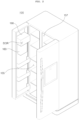
- a refrigerator 100 forms a rough outer shape by a case 110 having an internal space divided, although not shown, into a freezer compartment and a refrigerating compartment, a freezer compartment door 120 that shields the freezer compartment, and a refrigerator door 140 to shield the refrigerating compartment.
- the front surface of the freezer compartment door 120 and the refrigerating compartment door 140 is further provided with a door handle 121 protruding forward, so that a user easily grips and rotates the freezer compartment door 120 and the refrigerating compartment door 140.
- the front surface of the refrigerating compartment door 140 may be further provided with a home bar 180 which is a convenient means for allowing a user to take out a storage such as a beverage contained therein without opening the refrigerating compartment door 140.
- the front surface of the freezer compartment door 120 may be provided with a dispenser 160 which is a convenient means for allowing the user to easily take out ice or drinking water without opening the freezer compartment door 120, and a control panel 210 for controlling the driving operation of the refrigerator 100 and displaying the state of the refrigerator 100 being operated on a screen may be further provided in an upper side of the dispenser 160.
- the dispenser 160 is disposed in the front surface of the freezer compartment door 120, but is not limited thereto, and may be disposed in the front surface of the refrigerating compartment door 140.
- the control panel 210 may include an input device 220 formed of a plurality of buttons, and a display device 230 for displaying a control screen, an operation state, and the like.
- the display device 230 displays information such as a control screen, an operation state, a temperature inside the refrigerator, and the like.
- the display device 230 may display the set temperature of the freezer compartment and the set temperature of the refrigerating compartment.
- the display device 230 may be implemented in various ways, such as a liquid crystal display (LCD), a light emitting diode (LED), an organic light emitting diode (OLED), and the like.
- the display device 230 may be implemented as a touch screen capable of serving as the input device 220.
- the input device 220 may include a plurality of operation buttons.
- the input device 220 may include a freezer compartment temperature setting button (not shown) for setting the freezer compartment temperature, and a refrigerating compartment temperature setting button (not shown) for setting the refrigerating compartment temperature.
- the input device 220 may be implemented as a touch screen that may also function as the display device 230.
- the refrigerator according to an embodiment of the present disclosure is not limited to a double door type shown in the drawing, but may be a one door type, a sliding door type, a curtain door type, and the like regardless of its type.
- FIG. 2 is a perspective view of a door of the refrigerator of FIG. 1 .
- a freezer compartment 155 is disposed inside the freezer compartment door 120, and a refrigerating compartment 157 is disposed inside the refrigerating compartment door 140.
- An RF output device 190 may be disposed in the inner upper portion of the freezer compartment 155 to freeze the goods by using cold air in the freezer compartment while maintaining the freshness.
- the RF output device 190 is attached to the freezer compartment door 120, but the present disclosure is not limited thereto, and it is also possible that the RF output device190 is disposed in a space inside the freezer compartment instead of the freezer compartment door 120.
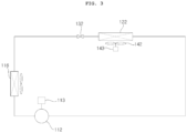
- FIG. 3 is a view schematically illustrating a configuration of the refrigerator of FIG. 1 .
- the refrigerator 100 may include a compressor 112, a condenser 116 for condensing a refrigerant compressed by the compressor 112, a freezer compartment evaporator 122 which is supplied with the refrigerant condensed in the condenser 116 to evaporate, and is disposed in a freezer compartment (not shown), and a freezer compartment expansion valve 132 for expanding the refrigerant supplied to the freezer compartment evaporator 122.
- the refrigerator 100 may further include a refrigerating compartment evaporator (not shown) disposed in a refrigerator compartment (not shown), a three-way valve (not shown) for supplying the refrigerant condensed in the condenser 116 to the refrigerating compartment evaporator (not shown) or the freezer compartment evaporator 122, and a refrigerating compartment expansion valve (not shown) for expanding the refrigerant supplied to the refrigerating compartment evaporator (not shown).
- a refrigerating compartment evaporator (not shown) disposed in a refrigerator compartment (not shown)
- a three-way valve for supplying the refrigerant condensed in the condenser 116 to the refrigerating compartment evaporator (not shown) or the freezer compartment evaporator 122
- a refrigerating compartment expansion valve not shown
- the refrigerator 100 may further include a gas-liquid separator (not shown) which separates the refrigerant passed through the evaporator 122 into a liquid and a gas.
- a gas-liquid separator (not shown) which separates the refrigerant passed through the evaporator 122 into a liquid and a gas.
- the refrigerator 100 may further include a refrigerating compartment fan (not shown) and a freezer compartment fan 144 that suck cold air that passed through the freezer compartment evaporator 122 and blow the sucked cold air into a refrigerating compartment (not shown) and a freezer compartment (not shown) respectively.
- the refrigerator 100 may further include a compressor driver 113 for driving the compressor 112, and a refrigerating compartment fan driver (not shown) and a freezer compartment fan driver 145 for driving the refrigerating compartment fan (not shown) and the freezer compartment 144.
- a damper (not shown) may be installed between the refrigerating compartment and the freezer compartment, and a fan (not shown) may forcibly blow the cold air generated in one evaporator to be supplied to the freezer compartment and the refrigerating compartment.
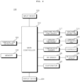
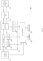
- FIG. 4 is a block diagram schematically illustrating the inside of the refrigerator shown in FIG. 1 .
- the refrigerator of FIG. 4 includes a compressor 112, a machine room fan 115, a freezer compartment fan 144, a main controller 310, a heater 330, an RF output device 190, an RF driver 195, a temperature detector 320, and a memory 240.
- the refrigerator may further include a compressor driver 113, a machine room fan driver 117, a freezer compartment fan driver 145, a heater driver 332, an RF driver 195, an RF output device 190, a display device 230, and an input device 220.
- the compressor 112 the machine room fan 115, and the freezer compartment fan 144 are described with reference to FIG. 2 .
- the input device 220 includes a plurality of operation buttons, and transmits a signal for an input freezer compartment set temperature or refrigerating compartment set temperature to the main controller 310.
- the display device 230 may display an operation state of the refrigerator. Meanwhile, the display device 230 is operable under the control of a display controller (not shown).
- the memory 240 may store data necessary for operating the refrigerator.
- the memory 240 may store power consumption information for each of the plurality of power consumption devices. In addition, the memory 240 may output corresponding power consumption information to the main controller 310 based on the operation of each power consumption device in the refrigerator.
- the temperature detector 320 detects a temperature in the refrigerator and transmits a signal for the detected temperature to the main controller 310.
- the temperature detector 320 detects the refrigerating compartment temperature and the freezer compartment temperature respectively.
- the temperature of each chamber in the refrigerating compartment or each chamber in the freezer compartment may be detected.
- the main controller 310 may control the compressor driver 113, the fan driver 117 or 145, and the RF driver 195 to finally control the compressor 112, the fan 115 or 144, and the RF output device 190.
- the fan driver may be the machine room fan driver 117 or the freezer compartment fan driver 145.
- the main controller 310 may output a corresponding speed command value signal to the compressor driver 113 or the fan driver 117 or 145 respectively.
- the compressor driver 113 and the freezer compartment fan driver 145 described above are provided with a compressor motor (not shown) and a freezer compartment fan motor (not shown) respectively, and each motor (not shown) may be operated at a target rotational speed under the control of the main controller 310.
- the machine room fan driver 117 includes a machine room fan motor (not shown), and the machine room fan motor (not shown) may be operated at a target rotational speed under the control of the main controller 310.
- each motor may be controlled by a switching operation in an inverter (not shown) or may be controlled at a constant speed by using an AC power source intactly.
- each motor may be any one of an induction motor, a Blush less DC (BLDC) motor, a synchronous reluctance motor (synRM) motor, and the like.
- the main controller 310 may control the overall operation of the refrigerator 100, in addition to the operation control of the compressor 112 and the fan 115 or 144.
- the main controller 310 may control the overall operation of the refrigerant cycle based on the set temperature from the input device 220.
- the main controller 310 may further control a three-way valve (not shown), a refrigerating compartment expansion valve (not shown), and a freezer compartment expansion valve 132, in addition to the compressor driver 113, the refrigerating compartment fan driver 143, and the freezer compartment fan driver 145.
- the operation of the condenser 116 may also be controlled.
- the main controller 310 may control the operation of the display device 230.
- the heater 330 may be a freezer compartment defrost heater. For removing frost attached to the freezer compartment evaporator 122, the freezer compartment defrost heater 330 may operate. To this end, the heater driver 332 may control the operation of the heater 330. Meanwhile, the main controller 310 may control the heater driver 332.
- the main controller 310 may output a driving signal to the RF driver 195 so as to control the RF output device 190.
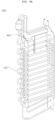
- FIG. 5A is a perspective view illustrating an example of an evaporator associated with the present disclosure
- FIG. 5B is a diagram referred to in the description of FIG. 5A .
- the evaporator 122 in a refrigerator 100x may be a freezer compartment evaporator, as illustrated in FIG. 2 .
- a sensor mounter 400 may be attached to the evaporator 122.
- FIG. 5B illustrates an example in which frost ICE is formed on the evaporator 122.
- the frost ICE is formed on a center portion of the evaporator 122, but the frost is not limited thereto and may be formed from a lower region of the evaporator 122 and grows upward.
- FIG. 6 is a perspective view illustrating another example of an evaporator associated with the present disclosure.
- a heater wire 230 coated on an insulation film may be attached to the evaporator 122 to remove the frost ICE illustrated in FIG. 5B .
- the operation of the defrost heater wire leads to a rise in temperature of the defrost heater wire to approximately 100 °C or higher.
- the heat transferred in the opposite direction Dot to the evaporator 122 causes a problem in that hot air is introduced into the refrigerating chamber or the freezer chamber, such that temperature inside the refrigerating chamber or the freezer chamber may rather increase.
- the present disclosure provides a method of performing a defrosting operation by using an RF signal while reducing heat generation, which will be describe below with reference to FIG. 7A and the following figures.
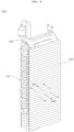
- FIG. 7A is a diagram illustrating an RF output device and an evaporator according to an embodiment of the present invention, which discloses a refrigerator according to claim 1.
- a refrigerator 100a includes an evaporator 122 configured to perform heat exchange by using a refrigerant compressed by a compressor 112; an RF output device 190 configured to output an RF signal to the evaporator 122 for removing frost formed on the evaporator 122; and a main controller 310 configured to control the RF output device 190.
- the evaporator 122 may be a freezer compartment evaporator, as illustrated in FIG. 2 .
- the sensor mounter 400 may be attached to the evaporator 122.
- the sensor mounter 400 may have a frame portion, and leg portions attached to the frame portion and extending in a vertical direction. Further, a pipe connector, which may be connected to a pipe of the evaporator 122, may be disposed at the respective leg portions.
- the frame portion may have an insertion space, into which a circuit board (not shown) having a frost sensor (not shown) for detecting the presence of frost may be inserted.
- the circuit board 450 illustrated in the drawing may be slidably inserted into the insertion space in the frame portion and may be fixed thereto.
- At least one of the first plate AND and the second plate CAP is disposed facing at least a lower portion of the evaporator 122. This is because, as illustrated in FIG. 5B , a position where frost is first formed on the evaporator 120 is the lower portion, and the frost grows upward from the lower portion.
- the evaporator 122 has a height of ho
- the first plate AND and the second plate CAP have a height of hb, which is lower than ho.
- At least one of the first plate AND and the second plate CAP may be electrically connected to an RF signal transmitter 312.
- the RF signal is output to the frost ICE on the evaporator 122.
- the frost ICE on the evaporator 122 may be removed using the RF signal, without using a separate defrost heater.
- the main controller 310 controls the frost ICE to phase change into a liquid by heat radiated from a plurality of metal fins of the evaporator 122; and after the phase change, the main controller 310 controls temperature of the phase changed liquid to increase by the water molecule movement based on the RF signal. Accordingly, defrosting is performed using the RF signal. Particularly, defrosting may be performed while reducing heat generation.
- temperature of the plurality of metal fins of the evaporator 122 is higher than temperature of the phase changed liquid near the metal fins. Accordingly, defrosting may be performed while reducing heat generation.
- thermoelectric cooler 100 As a frequency of the RF signal increases, temperature of heat radiated from the plurality of metal fins may increase. Accordingly, defrosting may be performed while reducing heat generation.
- the refrigerator 100 As the number of the metal fins of the evaporator 122 increases, or as a distance between the metals fins of the evaporator 122 decreases, heat radiated from the metal fins may increase. Accordingly, defrosting may be performed efficiently using the RF signal.
- the refrigerator 100 may further include a defrost heater for removing frost on the evaporator 122, and the main controller 310 may control the defrost heater to operate following the operation of the RF output device 190. Accordingly, defrosting may be performed efficiently using the RF signal.
- the refrigerator 100 may further include a defrost sensor for sensing the amount of frost on the evaporator 122, and the main controller 310 may change at least one of an output period and output power of the RF signal based on the amount of frost during the operation of the RF output device 190. Accordingly, defrosting may be performed efficiently using the RF signal.
- a frequency of the RF signal according to an embodiment of the present disclosure is preferably between 13.56 MHz and 433 MHz. Accordingly, defrosting may be performed efficiently using the RF signal.
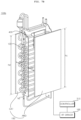
- FIG. 7B is a diagram illustrating an RF output device and an evaporator according to another embodiment of the present disclosure.
- a refrigerator 100b may include an evaporator 122 configured to perform heat exchange by using a refrigerant compressed by a compressor 112; an RF output device 190 configured to output an RF signal to the evaporator 122 for removing frost on the evaporator 122; and a main controller 310 configured to control the RF output device 190.
- the evaporator 122 has a height of ho
- the first plate AND and the second plate CAP have heights of hc and hd, respectively, which are almost the same as the height of the evaporator 122.
- the RF signal may be output over the whole area of the evaporator 122, such that frost may be removed from the entire area of the evaporator 122.
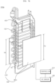
- FIG. 7C is a diagram illustrating an RF output device and an evaporator according to yet another embodiment of the present invention, which discloses a refrigerator according to claim 1.
- a refrigerator 100c includes an evaporator 122 configured to perform heat exchange by using a refrigerant compressed by a compressor 112; an RF output device 190 configured to output an RF signal to the evaporator 122 for removing frost on the evaporator 122; and a main controller 310 configured to control the RF output device 190.
- the RF output device 190 includes a first plate AND and a second plate CAP which are spaced apart from each other on the evaporator 122.
- the RF output device 190 may further include a heat insulating material 230 disposed on a surface opposite to at least one evaporator 122 of the first plate AND and the second plate CAP.
- frost formed on the evaporator 122 may be removed more efficiently.
- the heat insulating material has a height which is almost the same as the height ho of the evaporator 122, and is greater than the height ha of the first plate AND and the second plate CAP.
- FIG. 8 is a block diagram illustrating the interior of an RF output device according to an embodiment of the present disclosure.
- the RF output device 190 may be connected to the RF signal transmitter 312, and the RF signal transmitter 312 may be connected to the RF driver 195.
- the input device 220 may include a separate button for operating on or off the RF output device 190.
- the display device 230 may display information related to the operating on or off of the RF output device 190.
- the main controller 310 may control the RF output device 190 by using the RF driver 195.
- the RF driver 195 may include a frequency oscillator 332, a level adjuster 334, an amplifier 336, a directional coupler 338, and a power detector 342.
- the frequency oscillating device 332 oscillates to output an RF signal of a corresponding frequency, by a frequency control signal from the main controller 310.
- the frequency oscillator 322 may include a voltage controlled oscillator VCO. Based on the voltage level of the frequency control signal, the voltage controlled oscillator VCO oscillates a corresponding frequency. For example, as the voltage level of the frequency control signal becomes higher, the frequency oscillated and generated by the voltage controlled oscillator VCO becomes higher.
- the level adjuster 334 may oscillate the frequency signal oscillated by the frequency oscillator 332 to output an RF signal with a corresponding power based on the power control signal.
- the level adjuster 334 may include a voltage controlled attenuator VCA.
- the voltage controlled attenuator VCA Based on the voltage level of the power control signal, the voltage controlled attenuator VCA performs a correction operation so that an RF signal is output with a corresponding power. For example, as the voltage level of the power control signal becomes higher, the power level of the signal output from the voltage controlled attenuator VCA becomes higher.
- the amplifier 336 may output a RF signal by amplifying the oscillated frequency signal, based on the frequency signal oscillated by the frequency oscillator 332 and the power control signal by the level adjuster 334.
- the amplifier 336 may include a solid state power amplifier SSPA using a semiconductor device, and in particular, may include a Monolithic Microwave Integrated Circuits MMIC using a single substrate. Thus, the size thereof is reduced, and the integration of device can be achieved.
- the frequency oscillator 332, the level adjuster 334, and the amplifier 336, described above, may be implemented as a single device, which may be referred to as a solid state power oscillator SSPO.
- the directional coupler DC 338 transmits the RF signal amplified and output by the amplifier 336 to the RF signal transmitter 312.
- the RF signal output from the RF signal transmitter 312 is output to the goods in the RF output device 190.
- the RF signal that is not absorbed and reflected by the goods in the RF output device 190 may be input to the directional coupler 338 through the RF signal transmitter 312.
- the directional coupler 338 transfers the reflected RF signal to the main controller 310.
- the power detector 342 is disposed between the directional coupler 338 and the main controller 310, and detects the output power of the RF signal which is amplified and output by the amplifier 336 and transferred to the RF signal transmitter 312 via the directional coupler 338.
- the detected power signal is input to the main controller 310, and is used for a signal output efficiency calculation.
- the power detector 342 may be implemented of a diode device, or the like to detect a power.
- the power detector 342 is disposed between the directional coupler 338 and the main controller 310, and detects the power of the reflected RF signal reflected by the RF output device 190 and received by the directional coupler 338.
- the detected power signal is input to the main controller 310, and is used for signal output efficiency calculation.
- the power detector 342 may be implemented of a diode device, or the like to detect a power.
- the RF driver 195 is disposed between the amplifier 336 and the directional coupler 338, and may further include an isolation device (not shown) for passing through the RF signal in the case of transferring the RF signal amplified by the amplifier 336 to the RF output device 190, and blocking the RF signal reflected from the RF output device 190.
- the isolation device (not shown) may be implemented of an isolator.
- the main controller 310 may calculate signal output efficiency, based on the RF signal which is not absorbed and reflected by the goods among the RF signals emitted into the RF output device 190.
- the main controller 310 calculates signal output efficiency for each frequency of the plurality of RF signals.
- the main controller 310 may control a RF signal output section to be divided into a scan section and a main operation section so as to output signal efficiently.
- the main controller 310 may sequentially output a plurality of RF signals into the RF output device 190 during the scan section, and calculate signal output efficiency based on the reflected RF signal.
- the main controller 310 may output RF signals having different output periods respectively or output only the RF signal having a certain frequency, in the main operation section, based on the signal output efficiency calculated in the scan section. Meanwhile, it is preferable that the power of the RF signal in the main operation section is significantly higher than the power of the RF signal in the scan section. Thus, power consumption can be reduced.
- the main controller 310 may generate and output a frequency control signal to vary the output period of the RF signal based on the calculated signal output efficiency.
- the main controller 310 may control to output the RF signal of corresponding frequency, only when the signal output efficiency calculated for each frequency is equal to or greater than a set value.
- the power supply 114 may boost the power input to the refrigerator 100 to a high voltage and output to the RF driver 195.
- the power supply 114 may be implemented of a high voltage transformer or an inverter.
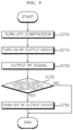
- FIG. 9 is a flowchart illustrating an operating method of a refrigerator according to an embodiment of the present disclosure
- FIGS. 10C to 13 are diagrams referred to in the description of FIG. 10A and 10B .
- the main controller 310 turns off the compressor 1120 (S705).
- the main controller 310 turns on the RF output device 190 (S710) for defrosting, such that the RF signal is output to the evaporator 122 (S720).
- the RF signal that causes the movement of water molecules in the goods is output to remove frost formed on the evaporator 122.
- a frequency of the RF signal is preferably between 13.56 MHz and 433 MHz.
- the frequency of the RF signal is between 13.56 MHz and 433 MHz, as it is not 2.4 GHz for high-speed vibration of water molecules, the water molecule motion is performed in a range where an object is not heated. Thus, frost may be removed efficiently while reducing the rise in ambient temperature.
- the main controller 310 determines whether an operating period is greater than or equal to a first period, or ambient temperature around the evaporator is greater than or equal to a first temperature (S730), and if so, the main controller 310 may turn off the RF output device 190 (S750).
- FIG. 10A illustrates an example in which the evaporator 122 is disposed between the first plate AND and the second plate CAP, and frost ICE is formed on the evaporator 122.
- the main controller 310 controls the frost to phase change into a liquid by heat radiated from the plurality of metal fins of the evaporator 122, and after the phase change, the main controller 310 controls temperature of the phase changed liquid to increase by the water molecule movement based on the RF signal. Accordingly, defrosting may be performed using the RF signal. Particularly, defrosting may be performed while reducing heat generation.
- FIG. 10B (a) illustrates an example in which the RF signal is output at a first time point to the frost ICE formed on the evaporator 122 within the first plate AND, in which as it is still at the initial stage, almost no frost ICE is melted.
- FIG. 10B (b) illustrates an example in which the RF signal is output at a second time point, after the first time point, to frost ICE formed on the evaporator 122 within the first plate AND.
- the plurality of metal fins react to the RF signal, such that a surrounding region OPb around the plurality of metal fins of the evaporator 122 is melted first.
- a defrosting method of a defrost heater is a method of removing frost using a defrost heater, in which a surrounding region around the heater is melted first, and a surrounding region around the plurality of metal fins of the evaporator 122 is melted last.
- the defrost heater method has a problem in that it is difficult to continuously remove frost formed in the surrounding region around the plurality of metal fins of the evaporator 122.
- the surrounding area OPb around the plurality of metal fins is melted first, and then other surrounding regions are sequentially melted, such that defrosting may be performed efficiently in a short time.
- FIG. 10C illustrates an ambient temperature curve Wava around the RF output device 190, and a temperature curve Wavb of frost on the evaporator 122.
- the main controller 310 may control the evaporator 122 to operate during periods, which are divided into a first period in which the RF signal is output such that temperature of a liquid around the evaporator 122 decreases, and a second period in which the liquid temperature increases after the first period, and then is maintained within a predetermined range.
- the first period corresponds to a predetermined period after the RF signal is output, and despite the output of the RF signal, the temperature of the liquid around the evaporator 122 may decrease due to the heat exchange in the evaporator 122.
- the second period may correspond to the entire section of the temperature curve Wavb of the frost illustrated in FIG. 10C .
- the liquid temperature may increase, and then may be maintained within a predetermined range. Accordingly, defrosting may be performed using the RF signal. Particularly, defrosting may be performed while reducing heat generation.
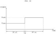
- FIG. 11 illustrates a range of frequencies output by the RF output device 190.
- a frequency range fscop of the RF signal is preferably between 13.56 MHz and 433 MHz.
- the frequency of the RF signal is lower than 13.56 MHz, movement of water molecules in the goods may not be active; and if the frequency of the RF signal is higher than 433 MHz, movement of water molecules in the goods may be too active, causing a temperature rise of the goods.
- the frequency range fscop of the RF signal used in the RF output device 190 is between 13.56 MHz and 433 MHz.
- the frequency of the RF signal may vary between 13.56 MHz and 433 MHz.
- the frequency of the RF signal may increase.
- power consumption may increase during the operation of the RF output device 190, rather than before the operation of the RF output device 190, which will be described below with reference to FIG. 12 .
- FIG. 12 illustrates an example in which power consumed by the compressor 112 before the operation of the RF output device 190 is Powa, and power consumed by the compressor 112 during the operation of the RF output device 190 is Powb which is greater than Powa.
- power consumed by the compressor 112 may increase more during the operation of the RF output device 190, in order to maintain a setting temperature of the freezer compartment at -18°C.
- the RF output device 190 mainly operates in a defrost interval, which will be described below with reference to FIGS. 13A and 13B .
- FIG. 13A illustrates an example of a defrosting operation.
- FIG. 13A is a timing diagram illustrating an operating period of a refrigerator and power consumption during the operating period of the refrigerator.
- a first section t1 is a cooling section, in which the compressor 112 is turned on to operate and a fan 144 is also turned on to operate. During the cooling section t1, first power L1 is consumed to perform the compressor 112.
- the first section t1 may be referred to as a deep cooling section or a cooling section before defrosting starts.
- a second section t2 is an idle section, in which the compressor 112 is turned off, and the fan 144 is also turned off. Meanwhile, the second section t2 may be referred to as an idle section before defrosting starts.
- the refrigerant in the evaporator 122 may be removed during the second section t2 before defrosting starts. Such operation may be referred to as pump down.
- a third section t3 is a defrost section, in which the RF output device 190 operates. Accordingly, frost near the evaporator 122 may be removed efficiently and stably.
- second power L2 which is lower than the power consumed in the cooling section t1, may be consumed during the defrost section t3.
- a fourth section t4 is an idle section after defrost. Accordingly, the compressor 112 may be turned off.
- a fifth section t5 is a cooling section after defrost, in which the compressor 112 is turned on to operate, and the fan 144 is also turned on to operate.
- the cooling section after defrost t5 the first power L1 is consumed to operate the compressor 112.
- a sixth section t6 is a second idle section after defrost, in which the compressor 112 may be turned off.
- a seventh section t7 is a second cooling section after defrost, in which the compressor 112 is turned on to operate, and the fan 144 is also turned on to operate.
- third power L3 which is lower than the first power L1 and the second power L2, is consumed, and then the first power L1 is consumed again.
- an eighth section t8 is a third idle section after defrost, in which the compressor 112 may be turned off.
- a ninth section t9 is a third cooling section after defrost, in which the compressor 112 is turned on to operate, and the fan 144 is also turned on to operate.
- the third power L3 which is lower than the first power L1 and the second power L2, is consumed, and then the first power L1 is consumed again.
- a tenth section t10 is a fourth idle section after defrost, in which the compressor 112 may be turned off.
- the main controller 310 may increase the frequency of the RF signal. Accordingly, defrosting may be performed efficiently by using the RF signal.
- the main controller 310 may control the RF signal to be output to the evaporator 122 during at least the defrost section t3 . Accordingly, defrosting may be performed efficiently by using the RF signal.
- the main controller 310 may control the RF signal to be output to the evaporator 122. Accordingly, defrosting may be performed stably by using the RF signal.
- the main controller 310 may control the compressor 112 to be turned off during the operation of the RF output device 190. Accordingly, power consumption may be reduced while performing defrosting using the RF signal.
- the main controller 310 may control the RF output device 190 to stop outputting the RF signal. Accordingly, a cooling operation may be performed smoothly during the cooling section, and power consumption of the refrigerator 100 may be reduced.
- the main controller 310 may control the RF output device 190 to operate in the idle section t2 and the defrost section t3 following the idle section t2. Accordingly, defrosting may be performed efficiently using the RF signal.
- the main controller 310 may control the RF output device 190 to be further operated during a portion of the cooling section before defrost t1 before the idle section t2. Accordingly, defrosting may be performed stably using the RF signal.
- the main controller 310 may control the RF output device 190 to be further operated during at least a portion of the idle section after defrost t4 following the idle section t2, and the cooling section after defrost t5 following the idle section after defrost t4. Accordingly, defrosting may be performed stably using the RF signal.
- the main controller 310 may operate the fan after stopping the operation of the RF output device 190 during the cooling section after defrost t5. Accordingly, a cooling operation may be performed smoothly during the cooling section, and power consumption of the refrigerator 100 may be reduced.
- the main controller 310 may control the second idle section after defrost t6 to perform after the fan is operated, and may control the second cooling section after defrost t7 to perform after the second idle section after defrost t6, and may continuously operate the fan during the second idle section after defrost t6 and the second cooling section after defrost t7. Accordingly, defrosting may be performed smoothly during the cooling section, and power consumption of the refrigerator 100 may be reduced.
- the main controller 310 may turn off the compressor 112. Accordingly, defrosting may be performed smoothly using the RF signal, and power consumption of the refrigerator 100 may be reduced.
- the main controller 310 may continuously operate the fan during the third idle section after defrost t8. Accordingly, cold air may be supplied continuously into the refrigerator 100.
- the main controller 310 may control power of the RF signal, output from the RF output device 190 during the third idle section after defrost t8, to be smaller than power of the RF signal during the defrost section t3. Accordingly, power consumption may be reduced while performing defrosting using the RF signal.
- the main controller 310 may turn off the compressor 112 while operating again the RF output device 190 during a portion of the second cooling section after defrost t7. Accordingly, power consumption may be reduced while performing defrosting using the RF signal.
- the main controller 310 may continuously operate the fan during a portion of the second cooling section after defrost t7. Accordingly, power consumption may be reduced while performing defrosting using the RF signal.
- the main controller 310 may control the power of the RF signal, output from the RF output device 190 during a portion of the second cooling section after defrost t7, to be smaller than power of the RF signal during the defrost section t3 . Accordingly, power consumption may be reduced while performing defrosting using the RF signal.
- the main controller 310 may stop the operation of the RF output device 190. Accordingly, defrosting may be performed efficiently using the RF signal.
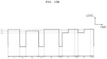
- FIG. 13B illustrates another example of a defrosting operation.
- FIG. 13B is different in that a cooling operation is performed during the eighth section t8 and the tenth section t10 which are idle periods in FIG. 13A , and particularly, the first power L1 is consumed in the eighth section t8 and the tenth section t10. Accordingly, cooling may be performed stably after defrosting.
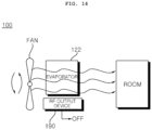
- FIG. 14 illustrates an example of a positional relationship between the fan 144, the evaporator 122, the RF output device 190, and the refrigerating compartment or the freezing compartment ROOM.
- the cold air evaporated by the evaporator 122 may be supplied to the refrigerating compartment or the freezer compartment ROOM by the operation of the fan 144.
- the RF output device 190 may be preferably turned off. Accordingly, cold air may be supplied efficiently.
- the RF output device 190 operates during defrosting, and the operation of the fan 144 may be temporarily stopped, thereby allowing efficient defrosting.
- the RF output device 190 may include at least one of the following: a power detector 342 configured to detect power of the RF signal reflected from the evaporator 122; a temperature detector 320 configured to detect temperature of the evaporator 122; and a camera (not shown) configured to photograph the evaporator 122. Accordingly, defrosting may be performed efficiently using the RF signal.
- the RF output device 190 may operate based on the signal detected by the power detector 342.
- the RF output device 190 may operate based on the detected temperature of the evaporator 122.
- the RF output device 190 may operate when defrost is detected from an image related to the evaporator 122 which is captured by the camera (not shown).
- the refrigerator 100 may further include: a fan configured to supply cold air, generated by heat exchange in the evaporator 122, to the freezer compartment 155; and a second RF output device (not shown) disposed in a cavity of the freezer compartment 155 and configured to output a second RF signal, such that the water molecules of goods in the cavity may move, thereby delaying freezing of the goods and maintaining freshness of the goods.
- a fan configured to supply cold air, generated by heat exchange in the evaporator 122, to the freezer compartment 155
- a second RF output device (not shown) disposed in a cavity of the freezer compartment 155 and configured to output a second RF signal, such that the water molecules of goods in the cavity may move, thereby delaying freezing of the goods and maintaining freshness of the goods.
- FIG. 15 is a flowchart illustrating an operating method of a refrigerator according to another embodiment of the present disclosure.
- the main controller 310 may turn off the compressor (S1505) and may perform a defrosting mode.
- the main controller 310 may determine whether the defrosting mode is in operation (S1506), and if an error occurs (S1508), the main controller 310 may perform a first defrosting stage (S1520).
- the error may refer to a case where temperature of the refrigerating compartment or the freezer compartment is greater than or equal to a reference temperature, i.e., a case where the temperature increases.
- the main controller 310 may reduce power of the RF signal output during the defrosting mode.
- the power of the RF signal in the first defrosting stage may be approximately 20 W. Accordingly, movement of water molecules occurs in frost on the evaporator 122, thereby preventing formation or further formation of frost on the evaporator 122.
- the power of the RF signal during defrosting before the first defrosting stage is performed may be approximately 60 W, thereby removing frost on the evaporator 122.
- the main controller 310 may end the first defrosting stage (S1550). Accordingly, defrosting may be performed efficiently.
- FIG. 16 is a flowchart illustrating an operating method of a refrigerator according to yet another embodiment of the present disclosure.
- the main controller 310 may perform defrosting (S1620).
- the main controller 310 determines whether a time to initiate defrosting in the freezer compartment is satisfied (S1622).
- the main controller 310 may determine whether deep cooling, corresponding to the first section t1 of FIG. 13A , is complete (S1624), and if the deep cooling is not complete, the main controller 310 may control the deep cooling, corresponding to the first section t1 of FIG. 13A , to be continuously performed (S1626).
- the main controller 310 may turn off the compressor 951655), and may perform a second defrosting stage (S1670).
- the power of the RF signal in the second defrosting stage may be approximately 60 W. Accordingly, movement of water molecules occurs in frost on the evaporator 122, thereby preventing formation or further formation of frost on the evaporator 122.
- the main controller 310 determines whether temperature of the refrigerating compartment is greater than or equal to a first temperature, or an operating period thereof is greater than or equal to the first period (S1672), and if so, the main controller 10 may end the second defrosting stage (S1680).
- the main controller 310 determines whether temperature of the freezer compartment is greater than or equal to a first temperature, or an operating period thereof is greater than or equal to a first period (S1674), and if so, the main controller 10 may end the second defrosting stage (S1680).
- the main controller 310 starts the compressor 122 after defrosting is performed (S1685), thereby efficiently performing the defrosting operation.
- the present disclosure may be applied to a refrigerator capable of performing defrosting.
Landscapes
- Engineering & Computer Science (AREA)
- Physics & Mathematics (AREA)
- Chemical & Material Sciences (AREA)
- Combustion & Propulsion (AREA)
- Mechanical Engineering (AREA)
- Thermal Sciences (AREA)
- General Engineering & Computer Science (AREA)
- Electromagnetism (AREA)
- Defrosting Systems (AREA)
- Devices That Are Associated With Refrigeration Equipment (AREA)
Claims (15)
- Réfrigérateur (100) comprenant :un compresseur (112) configuré pour comprimer un réfrigérant ;un évaporateur (122) configuré pour effectuer un échange de chaleur en utilisant le réfrigérant comprimé par le compresseur (112) ;un dispositif de sortie de fréquence radio (RF) (190) configuré pour sortir un signal RF vers l'évaporateur pour éliminer du givre sur l'évaporateur (122) ;dans lequel le dispositif de sortie RF (190) comprend une première plaque (AND) et une seconde plaque (CAT), dans lequel l'évaporateur (122) est positionné entre la première plaque (AND) et la seconde plaque (CAT) ;dans lequel une hauteur (ha) de la première plaque (AND) et/ou une hauteur de la seconde plaque (CAT) sont inférieures à une hauteur de l'évaporateur (122) ; etdans lequel la première plaque (AND) et/ou la seconde plaque (CAT) sont positionnées au niveau d'une zone correspondant à la portion inférieure de l'évaporateur (122) ; etun contrôleur (310) configuré pour commander le dispositif de sortie RF (190),dans lequel le contrôleur (310) est configuré pour :sur la base du signal RF, commander le changement de phase du givre en liquide par l'intermédiaire d'une chaleur irradiée depuis une pluralité d'ailettes métalliques de l'évaporateur (122) ; etaprès le changement de phase, commander une augmentation de température du liquide ayant changé de phase par l'intermédiaire d'un déplacement de molécules d'eau sur la base du signal RF ; etdans lequel le contrôleur (310) est configuré pour commander le dispositif de sortie RF (190) pendant une section de dégivrage (t3).
- Réfrigérateur (100) selon la revendication 1, dans lequel, à l'intermédiaire d'un fonctionnement du dispositif de sortie RF (190), une température de la pluralité d'ailettes métalliques de l'évaporateur (122) est plus élevée qu'une température du liquide ayant changé de phase à proximité des ailettes métalliques.
- Réfrigérateur (100) selon la revendication 1, dans lequel, lorsqu'une fréquence du signal RF augmente, la chaleur irradiée depuis la pluralité d'ailettes métalliques de l'évaporateur (122) augmente.
- Réfrigérateur (100) selon la revendication 1, dans lequel, lorsqu'une section de dégivrage (t3) diminue, ou lorsqu'une quantité de givre sur l' évaporateur (122) augmente, le contrôleur (310) est configuré pour augmenter la fréquence du signal RF.
- Réfrigérateur (100) selon la revendication 1, dans lequel, lorsqu'un nombre de la pluralité d'ailettes métalliques de l'évaporateur (122) augmente, ou lorsqu'une distance entre la pluralité d'ailettes métalliques de l'évaporateur (122) diminue, la chaleur irradiée depuis la pluralité d'ailettes métalliques augmente.
- Réfrigérateur (100) selon la revendication 1, comprenant en outre un ventilateur (144) configuré pour alimenter de l'air froid généré par un échange de chaleur dans l'évaporateur (122) jusque dans un compartiment de congélation,dans lequel pendantune portion d'une section de refroidissement (t1) avant la section de dégivrage (t3),une section de ralenti (t2) suivant la section de refroidissement (t1) avant la section de dégivrage (t3),la section de dégivrage (t3),une section de ralenti (t4) après la section de dégivrage (t3), etune portion d'une section de refroidissement (t5) après une section de dégivrage (t3),le contrôleur (310) est configuré pour sortir le signal RF vers l'évaporateur (122),dans lequel, après arrêt du fonctionnement du dispositif de sortie RF (190) pendant la section de refroidissement (t5) après la section de dégivrage (t3), le contrôleur (310) est configuré pour actionner le ventilateur (144).
- Réfrigérateur (100) selon la revendication 6, dans lequel le contrôleur (310) est configurée pour commander queune deuxième section de ralenti (t6) après la section de dégivrage (t3) est effectuée après actionnement du ventilateur (144), etune seconde section de refroidissement (t7) après la section de dégivrage (t3) est effectuée après la deuxième section de ralenti (t6) après la section de dégivrage (t3),dans lequel, pendant la deuxième section de ralenti (t6) après la section de dégivrage (t3) et la deuxième section de refroidissement (t7) après la section de dégivrage (t3), le contrôleur (310) est configuré pour actionner le ventilateur (144) en continu.
- Réfrigérateur (100) selon la revendication 7, dans lequel, pendant une troisième section de ralenti (t8) après la section de dégivrage (t3) suivant la deuxième section de refroidissement (t7) après la section de dégivrage (t3), le contrôleur (310) est configuré pour actionner à nouveau le dispositif de sortie RF (190) tout en désactivant le compresseur.
- Réfrigérateur (100) selon la revendication 8, dans lequel le contrôleur (310) est configuré pour commander une puissance du signal RF provenant du dispositif de sortie RF (190) pendant la troisième section de ralenti (t8) après la section de dégivrage (t3) pour qu'elle soit plus petite qu'une puissance du signal RF pendant la section de dégivrage (t3).
- Réfrigérateur (100) selon la revendication 1, dans lequel, en réponse au fait qu'une température de fin de dégivrage d'un compartiment de congélation (155) ou d'un compartiment de réfrigération (157) est supérieure ou égale à une première température, ou en réponse au fait qu'une période de dégivrage du dispositif de sortie RF (190) est supérieure ou égale à une première période, le contrôleur (310) est configuré pour arrêter le fonctionnement du dispositif de sortie RF (190).
- Réfrigérateur (100) of claim 1, comprenant en outre un chauffage de dégivrage (330),
dans lequel, après le fonctionnement du dispositif de sortie RF (190), le contrôleur est configuré pour actionner le chauffage de dégivrage. - Réfrigérateur (100) selon la revendication 1, comprenant en outre un capteur de givre configuré pour détecter une quantité de givre sur l'évaporateur (122),
dans lequel, pendant le fonctionnement du dispositif de sortie RF (190), le contrôleur (310) est configuré pour changer l'une au moins d'une période de sortie et d'une puissance de sortie du signal RF en accord avec la quantité du givre déposé. - Réfrigérateur (100) selon l'une quelconque des revendications 1 à 12, dans lequel le dispositif de sortie RF (190) comprend :
un matériau d'isolation de chaleur (230) disposé sur une surface de l'un au moins des évaporateurs (122) à l'opposé de la première plaque (AND) et de la seconde plaque (CAT). - Réfrigérateur (100) selon la revendication 13, dans lequel le dispositif de sortie RF (190) comprend l'un au moins des éléments suivants :un détecteur de puissance (342) configuré pour détecter une puissance du signal RF réfléchi depuis l'évaporateur (122) ;un détecteur de température (320) configuré pour détecter une température de l'évaporateur (122) ; etune caméra destinée à photographier l'évaporateur (122).
- Réfrigérateur (100) selon la revendication 1, dans lequel le contrôleur (310) est configuré pour :diviser une section de sortie de signal RF en une section de balayage et une section de fonctionnement principal ;sortir un signal RF d'une première puissance pendant la section de balayage ; etsortir un signal RF d'une seconde puissance sur la base d'un signal RF réfléchi depuis l'évaporateur (122) pendant la section de balayage,dans lequel le signal RF dans la section de fonctionnement principal a un niveau de puissance plus élevé que le signal RF dans la section de balayage.
Applications Claiming Priority (2)
| Application Number | Priority Date | Filing Date | Title |
|---|---|---|---|
| KR1020190037970A KR102828706B1 (ko) | 2019-04-01 | 2019-04-01 | 냉장고 |
| PCT/KR2020/004448 WO2020204595A1 (fr) | 2019-04-01 | 2020-04-01 | Réfrigérateur |
Publications (3)
| Publication Number | Publication Date |
|---|---|
| EP3951293A1 EP3951293A1 (fr) | 2022-02-09 |
| EP3951293A4 EP3951293A4 (fr) | 2022-12-21 |
| EP3951293B1 true EP3951293B1 (fr) | 2025-06-04 |
Family
ID=72667239
Family Applications (1)
| Application Number | Title | Priority Date | Filing Date |
|---|---|---|---|
| EP20784238.6A Active EP3951293B1 (fr) | 2019-04-01 | 2020-04-01 | Réfrigérateur |
Country Status (5)
| Country | Link |
|---|---|
| US (1) | US12247775B2 (fr) |
| EP (1) | EP3951293B1 (fr) |
| KR (1) | KR102828706B1 (fr) |
| CN (1) | CN113661368A (fr) |
| WO (1) | WO2020204595A1 (fr) |
Families Citing this family (1)
| Publication number | Priority date | Publication date | Assignee | Title |
|---|---|---|---|---|
| CN119778949A (zh) * | 2025-01-09 | 2025-04-08 | 长虹美菱股份有限公司 | 双循环冰箱及化霜控制方法 |
Citations (1)
| Publication number | Priority date | Publication date | Assignee | Title |
|---|---|---|---|---|
| US20170295614A1 (en) * | 2016-04-08 | 2017-10-12 | Illinois Tool Works, Inc. | Apparatus for simultaneously heating a plurality of food products |
Family Cites Families (31)
| Publication number | Priority date | Publication date | Assignee | Title |
|---|---|---|---|---|
| KR850006068A (ko) * | 1984-02-27 | 1985-09-28 | 에이치 알센즈 리차드 | 광학성에 제거장치 |
| DE3818491A1 (de) | 1988-05-31 | 1989-12-07 | Bosch Siemens Hausgeraete | Kapazitive hochfrequenz-auftauvorrichtung fuer ein haushaltgeraet |
| JPH0664081U (ja) * | 1993-02-08 | 1994-09-09 | 守利 長岡 | 蒸発器の着霜防止装置 |
| JPH09250863A (ja) * | 1996-03-18 | 1997-09-22 | Toshiba Corp | 冷凍冷蔵庫 |
| US7087876B2 (en) | 1998-06-15 | 2006-08-08 | The Trustees Of Dartmouth College | High-frequency melting of interfacial ice |
| JP2000121233A (ja) | 1998-10-20 | 2000-04-28 | Toshiba Corp | 冷凍冷蔵庫 |
| US6883603B2 (en) * | 2001-05-08 | 2005-04-26 | Lg Electronics, Inc. | Method for controlling operation of refrigerator with two evaporators |
| US6681580B2 (en) * | 2001-09-12 | 2004-01-27 | Manitowoc Foodservice Companies, Inc. | Ice machine with assisted harvest |
| US6817195B2 (en) * | 2002-03-29 | 2004-11-16 | General Electric Company | Reduced energy refrigerator defrost method and apparatus |
| JP2004212001A (ja) * | 2003-01-07 | 2004-07-29 | Sanyo Electric Co Ltd | 冷蔵庫 |
| KR100493692B1 (ko) * | 2003-07-23 | 2005-06-02 | 엘지전자 주식회사 | 냉장고용 제상히터 |
| KR100672571B1 (ko) * | 2004-08-11 | 2007-01-24 | 엘지전자 주식회사 | 냉장고용 증발기의 제상장치 |
| US20070101753A1 (en) * | 2005-10-06 | 2007-05-10 | Mile High Equipment Llc | Thermally conductive ice-forming surfaces incorporating short-duration electro-thermal deicing |
| KR20090106847A (ko) * | 2008-04-07 | 2009-10-12 | 삼성전자주식회사 | 냉장고 및 그 제어방법 |
| EP2352958A2 (fr) * | 2008-11-05 | 2011-08-10 | Trustees of Dartmouth College | Evaporateurs frigorifiques à dégivrage électrothermique à impulsion |
| US9095167B2 (en) * | 2009-01-08 | 2015-08-04 | Lg Electronics Inc. | Supercooling system for supercooling a stored liquid |
| JP2011012935A (ja) * | 2009-07-06 | 2011-01-20 | Kansai Electric Power Co Inc:The | 室外熱交換器及びこれを用いたヒートポンプシステム |
| US8931296B2 (en) * | 2009-11-23 | 2015-01-13 | John S. Chen | System and method for energy-saving inductive heating of evaporators and other heat-exchangers |
| KR101660045B1 (ko) * | 2010-02-23 | 2016-09-26 | 엘지전자 주식회사 | 냉장고 및 냉장고의 제어 방법 |
| KR101982776B1 (ko) * | 2012-12-10 | 2019-05-27 | 엘지전자 주식회사 | 냉장고 및 그 동작방법 |
| US10501972B2 (en) * | 2015-03-31 | 2019-12-10 | Follett Corporation | Refrigeration system and control system therefor |
| EP3399255B1 (fr) | 2016-04-07 | 2020-06-17 | Mayekawa Mfg. Co., Ltd. | Procédé de dégivrage par sublimation, dispositif de dégivrage par sublimation, et dispositif de refroidissement |
| KR101953809B1 (ko) * | 2016-05-25 | 2019-03-05 | 대한민국 | Rf 해동장치 |
| KR102725965B1 (ko) * | 2016-11-10 | 2024-11-05 | 엘지전자 주식회사 | 냉장고 및 그 제어 방법 |
| CN109000407B (zh) * | 2017-06-06 | 2020-05-26 | 青岛海尔股份有限公司 | 冰箱 |
| CN109000403B (zh) * | 2017-06-06 | 2020-05-26 | 海尔智家股份有限公司 | 用于解冻装置的解冻方法 |
| CN109000408B (zh) * | 2017-06-06 | 2020-06-23 | 青岛海尔股份有限公司 | 冰箱 |
| US10648728B2 (en) * | 2017-09-29 | 2020-05-12 | Nxp Usa, Inc. | Multifunctional radio frequency systems and methods for UV sterilization, air purification, and defrost operations |
| CN108050767B (zh) * | 2017-12-27 | 2020-06-23 | 青岛海尔股份有限公司 | 冰箱及其化霜控制方法 |
| CN108759177A (zh) * | 2018-05-09 | 2018-11-06 | 青岛海尔股份有限公司 | 蒸发器总成、具有该总成的冰箱及冰箱化霜控制方法 |
| CN110906635A (zh) * | 2018-09-17 | 2020-03-24 | 青岛海尔智能技术研发有限公司 | 换热器除霜装置、冷藏设备和冰箱 |
-
2019
- 2019-04-01 KR KR1020190037970A patent/KR102828706B1/ko active Active
-
2020
- 2020-04-01 WO PCT/KR2020/004448 patent/WO2020204595A1/fr not_active Ceased
- 2020-04-01 EP EP20784238.6A patent/EP3951293B1/fr active Active
- 2020-04-01 CN CN202080026649.4A patent/CN113661368A/zh active Pending
- 2020-04-01 US US17/600,266 patent/US12247775B2/en active Active
Patent Citations (1)
| Publication number | Priority date | Publication date | Assignee | Title |
|---|---|---|---|---|
| US20170295614A1 (en) * | 2016-04-08 | 2017-10-12 | Illinois Tool Works, Inc. | Apparatus for simultaneously heating a plurality of food products |
Also Published As
| Publication number | Publication date |
|---|---|
| WO2020204595A1 (fr) | 2020-10-08 |
| EP3951293A4 (fr) | 2022-12-21 |
| EP3951293A1 (fr) | 2022-02-09 |
| US20220163251A1 (en) | 2022-05-26 |
| KR102828706B1 (ko) | 2025-07-02 |
| US12247775B2 (en) | 2025-03-11 |
| KR20200116320A (ko) | 2020-10-12 |
| CN113661368A (zh) | 2021-11-16 |
Similar Documents
| Publication | Publication Date | Title |
|---|---|---|
| US11885538B2 (en) | Refrigerator | |
| KR101225977B1 (ko) | 공기조화기 및 그 제어 방법 | |
| EP2741032B1 (fr) | Réfrigérateur | |
| EP2578970B1 (fr) | Réfrigérateur | |
| EP3951293B1 (fr) | Réfrigérateur | |
| US20260098678A1 (en) | Refrigerator | |
| US12366406B2 (en) | Refrigerator | |
| US12449193B2 (en) | Refrigerator | |
| US12523420B2 (en) | Refrigerator | |
| US12487022B2 (en) | Refrigerator | |
| EP4148355A1 (fr) | Réfrigérateur | |
| JP6496570B2 (ja) | 冷却貯蔵庫 | |
| US12228326B2 (en) | Refrigerator | |
| JP2002061973A (ja) | 冷却装置 | |
| EP4148357A1 (fr) | Réfrigérateur | |
| KR20160009312A (ko) | 냉장고 및 그 제어방법 |
Legal Events
| Date | Code | Title | Description |
|---|---|---|---|
| STAA | Information on the status of an ep patent application or granted ep patent |
Free format text: STATUS: THE INTERNATIONAL PUBLICATION HAS BEEN MADE |
|
| PUAI | Public reference made under article 153(3) epc to a published international application that has entered the european phase |
Free format text: ORIGINAL CODE: 0009012 |
|
| STAA | Information on the status of an ep patent application or granted ep patent |
Free format text: STATUS: REQUEST FOR EXAMINATION WAS MADE |
|
| 17P | Request for examination filed |
Effective date: 20211101 |
|
| AK | Designated contracting states |
Kind code of ref document: A1 Designated state(s): AL AT BE BG CH CY CZ DE DK EE ES FI FR GB GR HR HU IE IS IT LI LT LU LV MC MK MT NL NO PL PT RO RS SE SI SK SM TR |
|
| DAV | Request for validation of the european patent (deleted) | ||
| DAX | Request for extension of the european patent (deleted) | ||
| REG | Reference to a national code |
Ref country code: DE Ref legal event code: R079 Free format text: PREVIOUS MAIN CLASS: F25D0021080000 Ipc: F25D0021060000 Ref country code: DE Ref legal event code: R079 Ref document number: 602020052333 Country of ref document: DE Free format text: PREVIOUS MAIN CLASS: F25D0021080000 Ipc: F25D0021060000 |
|
| A4 | Supplementary search report drawn up and despatched |
Effective date: 20221122 |
|
| RIC1 | Information provided on ipc code assigned before grant |
Ipc: H05B 6/62 20060101ALI20221116BHEP Ipc: H05B 6/50 20060101ALI20221116BHEP Ipc: F25D 21/06 20060101AFI20221116BHEP |
|
| GRAP | Despatch of communication of intention to grant a patent |
Free format text: ORIGINAL CODE: EPIDOSNIGR1 |
|
| STAA | Information on the status of an ep patent application or granted ep patent |
Free format text: STATUS: GRANT OF PATENT IS INTENDED |
|
| INTG | Intention to grant announced |
Effective date: 20241030 |
|
| GRAS | Grant fee paid |
Free format text: ORIGINAL CODE: EPIDOSNIGR3 |
|
| GRAA | (expected) grant |
Free format text: ORIGINAL CODE: 0009210 |
|
| STAA | Information on the status of an ep patent application or granted ep patent |
Free format text: STATUS: THE PATENT HAS BEEN GRANTED |
|
| AK | Designated contracting states |
Kind code of ref document: B1 Designated state(s): AL AT BE BG CH CY CZ DE DK EE ES FI FR GB GR HR HU IE IS IT LI LT LU LV MC MK MT NL NO PL PT RO RS SE SI SK SM TR |
|
| REG | Reference to a national code |
Ref country code: GB Ref legal event code: FG4D |
|
| REG | Reference to a national code |
Ref country code: CH Ref legal event code: EP |
|
| REG | Reference to a national code |
Ref country code: DE Ref legal event code: R096 Ref document number: 602020052333 Country of ref document: DE |
|
| REG | Reference to a national code |
Ref country code: IE Ref legal event code: FG4D |
|
| REG | Reference to a national code |
Ref country code: NL Ref legal event code: MP Effective date: 20250604 |
|
| PG25 | Lapsed in a contracting state [announced via postgrant information from national office to epo] |
Ref country code: FI Free format text: LAPSE BECAUSE OF FAILURE TO SUBMIT A TRANSLATION OF THE DESCRIPTION OR TO PAY THE FEE WITHIN THE PRESCRIBED TIME-LIMIT Effective date: 20250604 Ref country code: ES Free format text: LAPSE BECAUSE OF FAILURE TO SUBMIT A TRANSLATION OF THE DESCRIPTION OR TO PAY THE FEE WITHIN THE PRESCRIBED TIME-LIMIT Effective date: 20250604 |
|
| REG | Reference to a national code |
Ref country code: LT Ref legal event code: MG9D |
|
| PG25 | Lapsed in a contracting state [announced via postgrant information from national office to epo] |
Ref country code: GR Free format text: LAPSE BECAUSE OF FAILURE TO SUBMIT A TRANSLATION OF THE DESCRIPTION OR TO PAY THE FEE WITHIN THE PRESCRIBED TIME-LIMIT Effective date: 20250905 Ref country code: NO Free format text: LAPSE BECAUSE OF FAILURE TO SUBMIT A TRANSLATION OF THE DESCRIPTION OR TO PAY THE FEE WITHIN THE PRESCRIBED TIME-LIMIT Effective date: 20250904 |
|
| PG25 | Lapsed in a contracting state [announced via postgrant information from national office to epo] |
Ref country code: PL Free format text: LAPSE BECAUSE OF FAILURE TO SUBMIT A TRANSLATION OF THE DESCRIPTION OR TO PAY THE FEE WITHIN THE PRESCRIBED TIME-LIMIT Effective date: 20250604 |
|
| PG25 | Lapsed in a contracting state [announced via postgrant information from national office to epo] |
Ref country code: BG Free format text: LAPSE BECAUSE OF FAILURE TO SUBMIT A TRANSLATION OF THE DESCRIPTION OR TO PAY THE FEE WITHIN THE PRESCRIBED TIME-LIMIT Effective date: 20250604 |
|
| PG25 | Lapsed in a contracting state [announced via postgrant information from national office to epo] |
Ref country code: HR Free format text: LAPSE BECAUSE OF FAILURE TO SUBMIT A TRANSLATION OF THE DESCRIPTION OR TO PAY THE FEE WITHIN THE PRESCRIBED TIME-LIMIT Effective date: 20250604 |
|
| PG25 | Lapsed in a contracting state [announced via postgrant information from national office to epo] |
Ref country code: RS Free format text: LAPSE BECAUSE OF FAILURE TO SUBMIT A TRANSLATION OF THE DESCRIPTION OR TO PAY THE FEE WITHIN THE PRESCRIBED TIME-LIMIT Effective date: 20250904 |
|
| PG25 | Lapsed in a contracting state [announced via postgrant information from national office to epo] |
Ref country code: LV Free format text: LAPSE BECAUSE OF FAILURE TO SUBMIT A TRANSLATION OF THE DESCRIPTION OR TO PAY THE FEE WITHIN THE PRESCRIBED TIME-LIMIT Effective date: 20250604 |
|
| PG25 | Lapsed in a contracting state [announced via postgrant information from national office to epo] |
Ref country code: NL Free format text: LAPSE BECAUSE OF FAILURE TO SUBMIT A TRANSLATION OF THE DESCRIPTION OR TO PAY THE FEE WITHIN THE PRESCRIBED TIME-LIMIT Effective date: 20250604 |
|
| PG25 | Lapsed in a contracting state [announced via postgrant information from national office to epo] |
Ref country code: PT Free format text: LAPSE BECAUSE OF FAILURE TO SUBMIT A TRANSLATION OF THE DESCRIPTION OR TO PAY THE FEE WITHIN THE PRESCRIBED TIME-LIMIT Effective date: 20251006 |
|
| REG | Reference to a national code |
Ref country code: AT Ref legal event code: MK05 Ref document number: 1800678 Country of ref document: AT Kind code of ref document: T Effective date: 20250604 |
|
| PG25 | Lapsed in a contracting state [announced via postgrant information from national office to epo] |
Ref country code: IS Free format text: LAPSE BECAUSE OF FAILURE TO SUBMIT A TRANSLATION OF THE DESCRIPTION OR TO PAY THE FEE WITHIN THE PRESCRIBED TIME-LIMIT Effective date: 20251004 |
|
| PG25 | Lapsed in a contracting state [announced via postgrant information from national office to epo] |
Ref country code: AT Free format text: LAPSE BECAUSE OF FAILURE TO SUBMIT A TRANSLATION OF THE DESCRIPTION OR TO PAY THE FEE WITHIN THE PRESCRIBED TIME-LIMIT Effective date: 20250604 Ref country code: SM Free format text: LAPSE BECAUSE OF FAILURE TO SUBMIT A TRANSLATION OF THE DESCRIPTION OR TO PAY THE FEE WITHIN THE PRESCRIBED TIME-LIMIT Effective date: 20250604 |
|
| PG25 | Lapsed in a contracting state [announced via postgrant information from national office to epo] |
Ref country code: CZ Free format text: LAPSE BECAUSE OF FAILURE TO SUBMIT A TRANSLATION OF THE DESCRIPTION OR TO PAY THE FEE WITHIN THE PRESCRIBED TIME-LIMIT Effective date: 20250604 |
|
| PG25 | Lapsed in a contracting state [announced via postgrant information from national office to epo] |
Ref country code: EE Free format text: LAPSE BECAUSE OF FAILURE TO SUBMIT A TRANSLATION OF THE DESCRIPTION OR TO PAY THE FEE WITHIN THE PRESCRIBED TIME-LIMIT Effective date: 20250604 |
|
| PG25 | Lapsed in a contracting state [announced via postgrant information from national office to epo] |
Ref country code: SK Free format text: LAPSE BECAUSE OF FAILURE TO SUBMIT A TRANSLATION OF THE DESCRIPTION OR TO PAY THE FEE WITHIN THE PRESCRIBED TIME-LIMIT Effective date: 20250604 Ref country code: RO Free format text: LAPSE BECAUSE OF FAILURE TO SUBMIT A TRANSLATION OF THE DESCRIPTION OR TO PAY THE FEE WITHIN THE PRESCRIBED TIME-LIMIT Effective date: 20250604 |
|
| PG25 | Lapsed in a contracting state [announced via postgrant information from national office to epo] |
Ref country code: IT Free format text: LAPSE BECAUSE OF FAILURE TO SUBMIT A TRANSLATION OF THE DESCRIPTION OR TO PAY THE FEE WITHIN THE PRESCRIBED TIME-LIMIT Effective date: 20250604 |
|
| REG | Reference to a national code |
Ref country code: DE Ref legal event code: R097 Ref document number: 602020052333 Country of ref document: DE |
|
| PLBE | No opposition filed within time limit |
Free format text: ORIGINAL CODE: 0009261 |
|
| STAA | Information on the status of an ep patent application or granted ep patent |
Free format text: STATUS: NO OPPOSITION FILED WITHIN TIME LIMIT |
|
| PG25 | Lapsed in a contracting state [announced via postgrant information from national office to epo] |
Ref country code: DK Free format text: LAPSE BECAUSE OF FAILURE TO SUBMIT A TRANSLATION OF THE DESCRIPTION OR TO PAY THE FEE WITHIN THE PRESCRIBED TIME-LIMIT Effective date: 20250604 |
|
| REG | Reference to a national code |
Ref country code: CH Ref legal event code: L10 Free format text: ST27 STATUS EVENT CODE: U-0-0-L10-L00 (AS PROVIDED BY THE NATIONAL OFFICE) Effective date: 20260416 |