EP3951367A1 - Capteur optique de processus, tête de mesure, système de mesure comprenant les deux et procédé d'étalonnage et/ou de validation - Google Patents
Capteur optique de processus, tête de mesure, système de mesure comprenant les deux et procédé d'étalonnage et/ou de validation Download PDFInfo
- Publication number
- EP3951367A1 EP3951367A1 EP21185992.1A EP21185992A EP3951367A1 EP 3951367 A1 EP3951367 A1 EP 3951367A1 EP 21185992 A EP21185992 A EP 21185992A EP 3951367 A1 EP3951367 A1 EP 3951367A1
- Authority
- EP
- European Patent Office
- Prior art keywords
- light
- housing
- path
- optical
- designed
- Prior art date
- Legal status (The legal status is an assumption and is not a legal conclusion. Google has not performed a legal analysis and makes no representation as to the accuracy of the status listed.)
- Granted
Links
Images



Classifications
-
- G—PHYSICS
- G01—MEASURING; TESTING
- G01J—MEASUREMENT OF INTENSITY, VELOCITY, SPECTRAL CONTENT, POLARISATION, PHASE OR PULSE CHARACTERISTICS OF INFRARED, VISIBLE OR ULTRAVIOLET LIGHT; COLORIMETRY; RADIATION PYROMETRY
- G01J3/00—Spectrometry; Spectrophotometry; Monochromators; Measuring colours
- G01J3/02—Details
- G01J3/0297—Constructional arrangements for removing other types of optical noise or for performing calibration
-
- G—PHYSICS
- G01—MEASURING; TESTING
- G01N—INVESTIGATING OR ANALYSING MATERIALS BY DETERMINING THEIR CHEMICAL OR PHYSICAL PROPERTIES
- G01N21/00—Investigating or analysing materials by the use of optical means, i.e. using sub-millimetre waves, infrared, visible or ultraviolet light
- G01N21/84—Systems specially adapted for particular applications
- G01N21/85—Investigating moving fluids or granular solids
- G01N21/8507—Probe photometers, i.e. with optical measuring part dipped into fluid sample
-
- G—PHYSICS
- G01—MEASURING; TESTING
- G01N—INVESTIGATING OR ANALYSING MATERIALS BY DETERMINING THEIR CHEMICAL OR PHYSICAL PROPERTIES
- G01N21/00—Investigating or analysing materials by the use of optical means, i.e. using sub-millimetre waves, infrared, visible or ultraviolet light
- G01N21/01—Arrangements or apparatus for facilitating the optical investigation
-
- G—PHYSICS
- G01—MEASURING; TESTING
- G01J—MEASUREMENT OF INTENSITY, VELOCITY, SPECTRAL CONTENT, POLARISATION, PHASE OR PULSE CHARACTERISTICS OF INFRARED, VISIBLE OR ULTRAVIOLET LIGHT; COLORIMETRY; RADIATION PYROMETRY
- G01J3/00—Spectrometry; Spectrophotometry; Monochromators; Measuring colours
- G01J3/02—Details
- G01J3/0205—Optical elements not provided otherwise, e.g. optical manifolds, diffusers, windows
- G01J3/0235—Optical elements not provided otherwise, e.g. optical manifolds, diffusers, windows using means for replacing an element by another, for replacing a filter or a grating
-
- G—PHYSICS
- G01—MEASURING; TESTING
- G01J—MEASUREMENT OF INTENSITY, VELOCITY, SPECTRAL CONTENT, POLARISATION, PHASE OR PULSE CHARACTERISTICS OF INFRARED, VISIBLE OR ULTRAVIOLET LIGHT; COLORIMETRY; RADIATION PYROMETRY
- G01J3/00—Spectrometry; Spectrophotometry; Monochromators; Measuring colours
- G01J3/02—Details
- G01J3/0264—Electrical interface; User interface
-
- G—PHYSICS
- G01—MEASURING; TESTING
- G01J—MEASUREMENT OF INTENSITY, VELOCITY, SPECTRAL CONTENT, POLARISATION, PHASE OR PULSE CHARACTERISTICS OF INFRARED, VISIBLE OR ULTRAVIOLET LIGHT; COLORIMETRY; RADIATION PYROMETRY
- G01J3/00—Spectrometry; Spectrophotometry; Monochromators; Measuring colours
- G01J3/02—Details
- G01J3/027—Control of working procedures of a spectrometer; Failure detection; Bandwidth calculation
-
- G—PHYSICS
- G01—MEASURING; TESTING
- G01J—MEASUREMENT OF INTENSITY, VELOCITY, SPECTRAL CONTENT, POLARISATION, PHASE OR PULSE CHARACTERISTICS OF INFRARED, VISIBLE OR ULTRAVIOLET LIGHT; COLORIMETRY; RADIATION PYROMETRY
- G01J3/00—Spectrometry; Spectrophotometry; Monochromators; Measuring colours
- G01J3/02—Details
- G01J3/0291—Housings; Spectrometer accessories; Spatial arrangement of elements, e.g. folded path arrangements
-
- G—PHYSICS
- G01—MEASURING; TESTING
- G01N—INVESTIGATING OR ANALYSING MATERIALS BY DETERMINING THEIR CHEMICAL OR PHYSICAL PROPERTIES
- G01N21/00—Investigating or analysing materials by the use of optical means, i.e. using sub-millimetre waves, infrared, visible or ultraviolet light
- G01N21/01—Arrangements or apparatus for facilitating the optical investigation
- G01N21/03—Cuvette constructions
-
- G—PHYSICS
- G01—MEASURING; TESTING
- G01N—INVESTIGATING OR ANALYSING MATERIALS BY DETERMINING THEIR CHEMICAL OR PHYSICAL PROPERTIES
- G01N21/00—Investigating or analysing materials by the use of optical means, i.e. using sub-millimetre waves, infrared, visible or ultraviolet light
- G01N21/17—Systems in which incident light is modified in accordance with the properties of the material investigated
- G01N21/25—Colour; Spectral properties, i.e. comparison of effect of material on the light at two or more different wavelengths or wavelength bands
- G01N21/255—Details, e.g. use of specially adapted sources, lighting or optical systems
-
- G—PHYSICS
- G01—MEASURING; TESTING
- G01N—INVESTIGATING OR ANALYSING MATERIALS BY DETERMINING THEIR CHEMICAL OR PHYSICAL PROPERTIES
- G01N21/00—Investigating or analysing materials by the use of optical means, i.e. using sub-millimetre waves, infrared, visible or ultraviolet light
- G01N21/17—Systems in which incident light is modified in accordance with the properties of the material investigated
- G01N21/25—Colour; Spectral properties, i.e. comparison of effect of material on the light at two or more different wavelengths or wavelength bands
- G01N21/27—Colour; Spectral properties, i.e. comparison of effect of material on the light at two or more different wavelengths or wavelength bands using photo-electric detection ; circuits for computing concentration
- G01N21/274—Calibration, base line adjustment, drift correction
-
- G—PHYSICS
- G01—MEASURING; TESTING
- G01N—INVESTIGATING OR ANALYSING MATERIALS BY DETERMINING THEIR CHEMICAL OR PHYSICAL PROPERTIES
- G01N21/00—Investigating or analysing materials by the use of optical means, i.e. using sub-millimetre waves, infrared, visible or ultraviolet light
- G01N21/84—Systems specially adapted for particular applications
- G01N21/88—Investigating the presence of flaws or contamination
- G01N21/93—Detection standards; Calibrating baseline adjustment, drift correction
-
- G—PHYSICS
- G01—MEASURING; TESTING
- G01N—INVESTIGATING OR ANALYSING MATERIALS BY DETERMINING THEIR CHEMICAL OR PHYSICAL PROPERTIES
- G01N21/00—Investigating or analysing materials by the use of optical means, i.e. using sub-millimetre waves, infrared, visible or ultraviolet light
- G01N21/84—Systems specially adapted for particular applications
- G01N21/85—Investigating moving fluids or granular solids
- G01N21/8507—Probe photometers, i.e. with optical measuring part dipped into fluid sample
- G01N2021/8514—Probe photometers, i.e. with optical measuring part dipped into fluid sample with immersed mirror
-
- G—PHYSICS
- G01—MEASURING; TESTING
- G01N—INVESTIGATING OR ANALYSING MATERIALS BY DETERMINING THEIR CHEMICAL OR PHYSICAL PROPERTIES
- G01N21/00—Investigating or analysing materials by the use of optical means, i.e. using sub-millimetre waves, infrared, visible or ultraviolet light
- G01N21/84—Systems specially adapted for particular applications
- G01N21/85—Investigating moving fluids or granular solids
- G01N21/8507—Probe photometers, i.e. with optical measuring part dipped into fluid sample
- G01N2021/8514—Probe photometers, i.e. with optical measuring part dipped into fluid sample with immersed mirror
- G01N2021/8521—Probe photometers, i.e. with optical measuring part dipped into fluid sample with immersed mirror with a combination mirror cell-cuvette
-
- G—PHYSICS
- G01—MEASURING; TESTING
- G01N—INVESTIGATING OR ANALYSING MATERIALS BY DETERMINING THEIR CHEMICAL OR PHYSICAL PROPERTIES
- G01N21/00—Investigating or analysing materials by the use of optical means, i.e. using sub-millimetre waves, infrared, visible or ultraviolet light
- G01N21/84—Systems specially adapted for particular applications
- G01N21/85—Investigating moving fluids or granular solids
- G01N21/8507—Probe photometers, i.e. with optical measuring part dipped into fluid sample
- G01N2021/8528—Immerged light conductor
-
- G—PHYSICS
- G01—MEASURING; TESTING
- G01N—INVESTIGATING OR ANALYSING MATERIALS BY DETERMINING THEIR CHEMICAL OR PHYSICAL PROPERTIES
- G01N2201/00—Features of devices classified in G01N21/00
- G01N2201/08—Optical fibres; light guides
- G01N2201/086—Modular construction, e.g. disconnectable fibre parts
Definitions
- the invention relates to an optical process sensor, a measuring head that goes with it, a measuring system comprising the two, and a method for calibrating and/or validating.
- process sensors refer to sensors that are used to optimize, analyze and control manufacturing processes at the field level, such as in the chemical or pharmaceutical industry. These process sensors enable qualitative and quantitative analysis during the running process. For example, physical or chemical parameters are recorded in real time and used for system control or regulation.
- the DE 20 2013 101 907 U1 explained that with such process sensors it is necessary from time to time to clean the sample chamber or the sensor, for which purpose short-wave radiation such as gamma radiation or high temperatures can be used in particular. This entails considerable risks for the comparatively sensitive optics of the measuring probes; In particular, the aggressive radiation or the high temperatures can also destroy the optical part of the measuring probe, so that precautions must be taken to protect the sensitive optics from damage or even destruction when cleaning.
- the DE 20 2013 101 907 U1 proposes that the part that comes into direct contact with the sample to be examined be made detachable so that it can be easily removed from the sensitive parts of the sensor during cleaning.
- Optical sensors that are used, for example, in the food and pharmaceutical industries must be regularly validated to ensure that they function correctly.
- the properties to be checked here are regulated, among other things, in the Pharmacopoeia, USP (USA) and a corresponding counterpart in Europe. These are, for example, the wavelength accuracy, the photometric accuracy or linearity, the scattered light behavior and the resolving power with regard to the wavelength.
- test liquids and solid standards in the form of cuvettes or filter sets with the appropriate certificates are available for laboratory devices.
- the laboratory devices can easily be validated with these standards.
- the cuvette standards or the filters are placed in the beam path of the instrument to be validated.
- Process sensors often work with measuring cells, which are connected to a decoupled measuring system via fiber optics with the light sources and receivers. To validate the measuring system, the light guides are removed from the corresponding measuring cell and connected to a cuvette holder.
- the object of the invention is to validate and calibrate process sensors in a simple manner.
- an optical process sensor for measuring at least one measured variable of a medium in a container, comprising: a housing; a light source in the housing for emitting transmission light; a light receiver in the housing for receiving received light; and a first optical-mechanical interface, comprising: a first optical section, which protrudes from the housing, with a first path and a first light guide, wherein the first light guide is configured such that transmitted light via the first light guide from the light source into the first Path is guided, and transmitted light is coupled out of the housing, and with a second path and a second light line, the second light line being designed in such a way that received light is coupled into the interior of the housing and is guided from the second path to the light receiver via the second light line , and a first mechanical portion configured as an integral part of the housing.
- One embodiment provides that the first and second light guide is designed as an optical waveguide.
- first and second path are designed as two separate rod-shaped, in particular cylindrical, continuations, which are connected to the housing in particular by screwing, gluing, welding or by frictional locking, with the first and second light guide inside the continuations is led.
- the first and second path at the end area remote from the process sensor in particular in each case, comprises an optical element, in particular a window and/or a lens, the optical element being transparent for the transmitted light and received light.
- the senor is designed as a spectrometer.
- an optical process sensor which is designed to measure at least one measured variable of a medium in a container
- the measuring head comprising: a housing which is designed to connect the sensor to the container; a second optical-mechanical interface, comprising a second optical section which is complementary to a first optical section.
- the second optical section is designed as a recess in the housing.
- the first optical section includes a third path that receives transmitted light and couples it into the interior of the housing.
- the third path leads the transmitted light to a deflection element.
- the first optical section includes a fourth path, which receives transmitted light, guides it through an area through which a medium flows, the transmitted light being converted into received light by the medium, and couples received light out of the housing.
- the second opto-mechanical interface comprises a second mechanical section which is complementary to a first mechanical section and is designed as an integral part of the housing.
- the measuring head includes a deflection element in the housing, which deflects the transmitted light or received light from the third path into the fourth path or vice versa.
- the area through which the medium flows is designed as a further recess in the housing.
- the measuring head thus comprises an optical process sensor which is designed to measure at least one measured variable of a medium in a container, the measuring head comprising: a housing which is designed to connect the sensor to the container; a second optical-mechanical interface, comprising a second optical section which is complementary to a first optical section and which is designed as a recess is configured in the housing, a third path, which receives transmitted light, couples it into the interior of the housing and leads to a deflection element, and a fourth path, which receives transmitted light from the deflection element, through an area through which the medium flows, the transmitted light being converted by the medium into received light and decouples received light from the housing, and a second mechanical section, which is complementary to a first mechanical section and is designed as an integral part of the housing, the deflection element, which is arranged in the housing, and the area through which the medium flows, which is a further recess of the housing is designed.
- the measuring head comprises an optical process sensor, which is designed to measure at least one measured variable of a medium in a container, the measuring head comprising: a housing, which is designed to connect the sensor to the container; a second opto-mechanical interface, comprising a second optical section, which is complementary to a first optical section and is designed as a recess in the housing, couples a third path, which receives transmitted light, into the interior of the housing, through an area through which the medium flows, wherein the transmitted light is converted by the medium into received light, and leads received light to a deflection element, and a fourth path that receives received light from the deflection element and decouples it from the housing, and a second mechanical section that is complementary to a first mechanical section and that acts as an integral Part of the housing is configured, the deflection element, which is arranged in the housing, and the area through which the medium flows, which is configured as a further recess of the housing.
- the medium-flow path can thus be arranged in the third or in the fourth path.
- an opto-mechanical interface on the sensor and measuring head makes it possible to decouple different types of measuring heads such as immersion probes or flow cells from process sensors. This allows the measuring head to remain in the process and keeps it closed for the further validation process of the sensor.
- the removed sensor with the opto-mechanical interface can now be used for the validation process.
- a validation adapter which is regarded as a special configuration of a measuring head
- the sensor can be checked easily.
- One embodiment provides that the deflection element deflects the transmitted light by 180°.
- the deflection element is designed as a prism.
- third and fourth path are designed as two separate rod-shaped, in particular cylindrical, recesses.
- the third and fourth path in particular each, includes an optical element, in particular a window and/or a lens, the optical element being transparent for the transmitted light and received light.
- the third or fourth path includes a window to the area through which the medium flows, the window being transparent for the transmitted light and received light.
- the measuring head is designed as an immersion probe.
- the measuring head is designed as a flow probe.
- the measuring head is designed as a calibration and validation device.
- optical-mechanical interface Different measuring heads can be easily exchanged.
- the "actual” measuring head e.g. a flow probe or immersion probe, remains in the process.
- a calibration and validation device is placed on the same opto-mechanical interface.
- the optical path is the same as in the process and the sensor can be calibrated.
- the calibration and validation device includes a cuvette holder with a holder for a cuvette, the holder forming the area through which the medium flows.
- the cuvette holder includes a solid standard.
- the calibration and validation device includes a cuvette changer.
- the calibration and validation device includes a filter wheel or filter changer.
- an optical measuring system comprising an optical process sensor as described above and a measuring head as described above, the second optical section accommodating the first optical section to form an optical connection with a light path from the light source, first light line, first path, third To enable path, deflection element, fourth path, second path, second light line and light receiver, and a mechanical connection of the optical process sensor and measuring head via the first mechanical section and second mechanical section.
- the mechanical connection is detachable, in particular the first mechanical section and the second mechanical section are designed such that there is a screw connection, in particular the first mechanical section and the second mechanical section include bores and/or threads for screws.
- the object is further achieved by a method for calibrating and/or validating an optical process sensor, comprising the steps of: removing the sensor from a measuring head, which is designed as a flow probe or immersion probe; Attaching the sensor to a measuring head which is designed as a calibration and validation device; calibrating and validating the sensor using the calibration and validation device; removing the sensor from the calibration and validation device; and reattaching the sensor to the flow probe or submersible probe.
- the claimed measuring system in its entirety has the reference number 100 and is, for example, in Fig. 2d shown. First, the individual components will be discussed, namely a process sensor 1 and a measuring head 51.
- Figures 1a and 1b show the sensor 1 with the housing 2.
- the sensor is an optical sensor. This is, for example, a spectrometer with a light source 3 and a light receiver 4.
- the light source 3 emits transmitted light 5 and the light receiver 4 receives received light 6, which is produced by converting the transmitted light 5 on the medium to be measured (see below).
- the light 5 emitted by the light source 3 is thus converted by the medium, for example absorbed, scattered or fluorescent light is produced.
- This converted light 6 is picked up by the receiver 4 and converted into an electrical signal.
- the sensor 1 comprises a first opto-mechanical interface 10, which consists of an optical section 11 and a mechanical section 21.
- the mechanical section 21 is used to connect the sensor 1 to the measuring head 51, for example by screwing, with appropriate devices, ie holes, threads or bores 22 and 72 being present.
- the mechanical section 21 is an integral part of the housing 2.
- the optical section 11 projects out of the housing 2 .
- This comprises a first path 12 and a first light guide 13 , for example an optical waveguide or a free beam guide, which introduces the transmitted light 5 from the light source 3 into the first path 12 and then decouples the transmitted light 5 from the housing 2 .
- This also includes a second path 14 and a second light line 15, such as an optical waveguide or a free beam guide, which couples the received light 6 into the interior of the housing 2 and guides it from the second path 14 to the light receiver 4 via the second light line 15.
- the paths 12, 14 are separate, cylindrical continuations, which are screwed to the housing 2, for example, with the optical waveguides 13, 15 being routed inside.
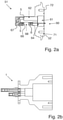
- Figure 2a shows the measuring head 51 in cross section, Figure 2c in a side view.
- Figure 2b shows sensor 1, right next to it Figure 2a .
- Fig. 2d shows the measuring system 100 in the assembly of sensor 1 and head 51.
- the measuring head 51 includes a second opto-mechanical interface 60, which consists of an optical section 61 and a mechanical section 71.
- the mechanical section 71 is used to connect the measuring head 51 to the sensor 1, for example by screwing, with corresponding devices, ie for example holes, Threads or holes 22 and 72 are present.
- the mechanical section 71 is an integral part of the housing 52.
- the housing 52 is designed for connection to a container.
- the housing 52 comprises corresponding connection means.
- the connection means can be designed as a welded or flanged connection, e.g. made of stainless steel. However, other configurations are possible.
- the measuring medium to be measured is located in the container.
- the container can be a container, boiler, pipe, pipeline or the like.
- the second opto-mechanical interface 60 initially comprises a second optical section 61 which is complementary to a first optical section 11 and is designed as a recess in the housing 52 .
- the deflection element 67 deflects the transmitted light 5 by 180° and is designed as a prism.
- the third and fourth paths 62, 64 are designed as two separate rod-shaped, in particular cylindrical, recesses.
- the third and fourth pathways 62, 64 are designed to complement the first and second pathways 12, 14 so that the continuations fit snugly into the recesses. If the sensor 1 and the head 51 are assembled and mechanically fixed via the mechanical sections 11, 61, the two optical sections 11, 51 are positioned in such a way that the transmitted light 5 or the received light 6 is guided ideally from the sensor 1 into the head 51 or vice versa will. There are designs with lenses 16 (as shown) or windows.
- Transparent windows 66 separate the interior from the media (for clarity, the reference number indicates only the left window).
- the path 68 through which the medium flows can be arranged in the third or in the fourth path 62 , 64 .
- the Figures 2a-2d show the configuration of the measuring head 51 as an immersion probe.
- the measuring head 51 is located in the medium to be measured and also remains there.
- the measuring head 51 can also be removed from the process and from the sensor, for example for maintenance purposes such as changing seals.
- Figures 3a-3d are systematically constructed in the same way, with the measuring head 51 being designed as a flow probe.
- Medium flows through an inlet 69a and leaves the flow probe again at the outlet 69b. Inside is the area 68 through which the medium flows.
- the measuring head 51 can be designed as a calibration and validation device.
- the sensor 1 is thus removed and the measuring head 51 in the configuration as a calibration and validation device, which also has a second opto-mechanical interface 60, is attached to the sensor 1.
- a configuration of the calibration and validation device is a cuvette holder.
- the holder 80 into which a cuvette 81 is placed, is located at the area 68 through which the medium flows.
- the cuvette 81 can be configured as a standard, for example as a solid body standard. Shows the assembled condition Figure 4d , whereby the cuvette holder is not fully assembled.
- Figure 4e shows the configuration as a cuvette holder with an inserted sensor, only the first optical section 11 being visible. Some components are drawn transparently to show the assembly, especially the optical sections 11, 61.
- the sensor 1 can be calibrated, validated and, if necessary, adjusted by means of the cuvette holder 51 .
- the calibration and validation device can also be designed as a cuvette changer, filter wheel or filter changer. Different absorptions can be set on the filter wheel so that different situations can be simulated by turning it.
- the senor 1 is removed from the calibration and validation device and can be reconnected to the other measuring head, for example the immersion probe or the flow probe.
Landscapes
- Physics & Mathematics (AREA)
- Spectroscopy & Molecular Physics (AREA)
- General Physics & Mathematics (AREA)
- Chemical & Material Sciences (AREA)
- Pathology (AREA)
- Analytical Chemistry (AREA)
- Biochemistry (AREA)
- General Health & Medical Sciences (AREA)
- Health & Medical Sciences (AREA)
- Immunology (AREA)
- Life Sciences & Earth Sciences (AREA)
- Engineering & Computer Science (AREA)
- Human Computer Interaction (AREA)
- Mathematical Physics (AREA)
- Theoretical Computer Science (AREA)
- Investigating Or Analysing Materials By Optical Means (AREA)
- Optical Measuring Cells (AREA)
Applications Claiming Priority (1)
| Application Number | Priority Date | Filing Date | Title |
|---|---|---|---|
| DE102020120718.2A DE102020120718A1 (de) | 2020-08-05 | 2020-08-05 | Optischer Prozesssensor, Messkopf, Messsystem umfassend die beiden und Verfahren zum Kalibrieren und/oder Validieren |
Publications (2)
| Publication Number | Publication Date |
|---|---|
| EP3951367A1 true EP3951367A1 (fr) | 2022-02-09 |
| EP3951367B1 EP3951367B1 (fr) | 2026-04-29 |
Family
ID=76958748
Family Applications (1)
| Application Number | Title | Priority Date | Filing Date |
|---|---|---|---|
| EP21185992.1A Active EP3951367B1 (fr) | 2020-08-05 | 2021-07-16 | Capteur optique de processus, tête de mesure, système de mesure comprenant les deux et procédé d'étalonnage et/ou de validation |
Country Status (4)
| Country | Link |
|---|---|
| US (1) | US11747200B2 (fr) |
| EP (1) | EP3951367B1 (fr) |
| CN (1) | CN114112904A (fr) |
| DE (1) | DE102020120718A1 (fr) |
Families Citing this family (1)
| Publication number | Priority date | Publication date | Assignee | Title |
|---|---|---|---|---|
| US12360006B2 (en) * | 2023-06-02 | 2025-07-15 | Viavi Solutions Inc. | Changeable tip for optical fiber inspection device with detectable tip orientation |
Citations (10)
| Publication number | Priority date | Publication date | Assignee | Title |
|---|---|---|---|---|
| EP0660106A1 (fr) * | 1993-12-22 | 1995-06-28 | Hellma GmbH & Co. KG Glastechnische-optische Werkstätten | Dispositif avec spectrophotomètre et fibres optiques |
| DE10149879A1 (de) * | 2001-10-10 | 2003-04-30 | Orban & Trau Xantec | Vorrichtung zur spektralphotometrischen Analyse von flüssigen Medien |
| US20080249435A1 (en) * | 2005-10-15 | 2008-10-09 | Hans-Peter Haar | Test element and test system for examining a body fluid |
| WO2012033466A1 (fr) * | 2010-09-08 | 2012-03-15 | Nitto Denko Corporation | Biocapteur à guide d'ondes |
| DE202013101907U1 (de) | 2013-05-02 | 2013-05-16 | Viacheslav Artyushenko | Frontelement für eine optische Messsonde und Messsondenvorrichtung |
| US9304079B2 (en) * | 2011-12-15 | 2016-04-05 | Mettler-Toledo Gmbh | Gas analyser |
| EP3067686A1 (fr) * | 2015-03-13 | 2016-09-14 | Yokogawa Electric Corporation | Élément optique, sonde de transmission, récipient d'échantillon, dispositif optique et procédé de mesure de transmission par immersion |
| US20170146450A1 (en) * | 2015-11-19 | 2017-05-25 | Sentelligence, Inc. | Species specific sensor for exhaust gases and method thereof |
| US20170292909A1 (en) * | 2008-11-24 | 2017-10-12 | Ge Healthcare Bio-Sciences Ab | Flow cell optical detection system |
| EP3561488A1 (fr) * | 2018-04-25 | 2019-10-30 | Yokogawa Electric Corporation | Analyseur de gaz |
Family Cites Families (10)
| Publication number | Priority date | Publication date | Assignee | Title |
|---|---|---|---|---|
| US4786171A (en) * | 1986-07-29 | 1988-11-22 | Guided Wave, Inc. | Spectral analysis apparatus and method |
| US6667808B2 (en) * | 2000-03-08 | 2003-12-23 | Thermo Electron Scientific Instruments Corporation | Multifunctional fourier transform infrared spectrometer system |
| DE10257716B4 (de) * | 2002-12-11 | 2005-12-29 | Institut für Textilchemie der Deutschen Institute für Textil- und Faserforschung Stuttgart | Optischer Sensor zur Bestimmung von Farbstoffkonzentrationen in flüssigen Medien und Verfahren zu dessen Betrieb |
| EP1685388B9 (fr) * | 2003-11-19 | 2008-02-13 | Raumedic Ag | Dispositif et procede pour analyser un echantillon liquide |
| DE202008003764U1 (de) * | 2008-03-18 | 2008-05-21 | J & M Analytische Mess- Und Regeltechnik Gmbh | Vorrichtung zur optischen Messung von Stoffen |
| WO2010027982A2 (fr) * | 2008-09-02 | 2010-03-11 | Microptix Technologies, Llc | Mécanisme adaptateur pour dispositif portable de détection spectrale |
| GB2542855B (en) * | 2015-10-02 | 2017-10-11 | Smart Fibres Ltd | Monitoring probe |
| DE102016117733A1 (de) * | 2015-10-09 | 2017-04-13 | Endress+Hauser Conducta Gmbh+Co. Kg | Messeinrichtung |
| US10690590B2 (en) * | 2016-04-05 | 2020-06-23 | Viavi Solutions Inc. | Light pipe for spectroscopy |
| DE102017114317A1 (de) * | 2016-07-27 | 2018-02-01 | Endress+Hauser Conducta Gmbh+Co. Kg | Spektrometrisches Messgerät |
-
2020
- 2020-08-05 DE DE102020120718.2A patent/DE102020120718A1/de active Pending
-
2021
- 2021-07-16 EP EP21185992.1A patent/EP3951367B1/fr active Active
- 2021-07-29 US US17/388,493 patent/US11747200B2/en active Active
- 2021-07-30 CN CN202110873429.1A patent/CN114112904A/zh active Pending
Patent Citations (10)
| Publication number | Priority date | Publication date | Assignee | Title |
|---|---|---|---|---|
| EP0660106A1 (fr) * | 1993-12-22 | 1995-06-28 | Hellma GmbH & Co. KG Glastechnische-optische Werkstätten | Dispositif avec spectrophotomètre et fibres optiques |
| DE10149879A1 (de) * | 2001-10-10 | 2003-04-30 | Orban & Trau Xantec | Vorrichtung zur spektralphotometrischen Analyse von flüssigen Medien |
| US20080249435A1 (en) * | 2005-10-15 | 2008-10-09 | Hans-Peter Haar | Test element and test system for examining a body fluid |
| US20170292909A1 (en) * | 2008-11-24 | 2017-10-12 | Ge Healthcare Bio-Sciences Ab | Flow cell optical detection system |
| WO2012033466A1 (fr) * | 2010-09-08 | 2012-03-15 | Nitto Denko Corporation | Biocapteur à guide d'ondes |
| US9304079B2 (en) * | 2011-12-15 | 2016-04-05 | Mettler-Toledo Gmbh | Gas analyser |
| DE202013101907U1 (de) | 2013-05-02 | 2013-05-16 | Viacheslav Artyushenko | Frontelement für eine optische Messsonde und Messsondenvorrichtung |
| EP3067686A1 (fr) * | 2015-03-13 | 2016-09-14 | Yokogawa Electric Corporation | Élément optique, sonde de transmission, récipient d'échantillon, dispositif optique et procédé de mesure de transmission par immersion |
| US20170146450A1 (en) * | 2015-11-19 | 2017-05-25 | Sentelligence, Inc. | Species specific sensor for exhaust gases and method thereof |
| EP3561488A1 (fr) * | 2018-04-25 | 2019-10-30 | Yokogawa Electric Corporation | Analyseur de gaz |
Also Published As
| Publication number | Publication date |
|---|---|
| US11747200B2 (en) | 2023-09-05 |
| DE102020120718A1 (de) | 2022-02-10 |
| US20220042846A1 (en) | 2022-02-10 |
| CN114112904A (zh) | 2022-03-01 |
| EP3951367B1 (fr) | 2026-04-29 |
Similar Documents
| Publication | Publication Date | Title |
|---|---|---|
| DE112011103757T5 (de) | UV-Miniatursensor mit Einweg-Durchflusszelle | |
| DE4443016A1 (de) | Gasanalytisches Meßgerät | |
| DE102017114317A1 (de) | Spektrometrisches Messgerät | |
| EP2681531B1 (fr) | Cellule de mesure à circulation pour la réception d'éléments de mesure | |
| DE102010038428A1 (de) | Optisches Messsystem | |
| EP3951367A1 (fr) | Capteur optique de processus, tête de mesure, système de mesure comprenant les deux et procédé d'étalonnage et/ou de validation | |
| DE69422922T2 (de) | Fluoreszenzdetektor und vorrichtung zum halten einer auswechselbaren probenküvette in einen fluoreszenzdetektor | |
| DE202021102073U1 (de) | Optische Analysevorrichtung zur Bestimmung einer Kenngröße eines Mediums, Gehäuse und Gesamtsystem | |
| EP1929280B1 (fr) | Dispositif de laboratoire pour realiser simultanement des reactions dans plusieurs echantillons | |
| WO2001075419A1 (fr) | Dispositif optique destine a une mesure multiple simultanee par polarimetrie et spectrometrie, et procede de reglage/surveillance de processus physico-chimiques et biotechniques a l'aide de ce dispositif | |
| DE3541165A1 (de) | Vorrichtung zur kontinuierlichen bestimmung von konzentrationsaenderungen in stoffgemischen | |
| DE10149879B4 (de) | Vorrichtung zur spektralphotometrischen Analyse von flüssigen Medien | |
| EP2049883A1 (fr) | Sonde de mesure optique pour surveillance de processus | |
| EP2270435A2 (fr) | Doigt de capteur optique | |
| EP2416145B1 (fr) | Dispositif destiné à l'analyse d'un fluide | |
| EP2137510A1 (fr) | Détecteur de particules pour des milieux liquides ou gazeux en écoulement | |
| EP3814477B1 (fr) | Récipients de bioprocédé munis d'un dispositif de mesure optique | |
| WO2009115282A1 (fr) | Sonde optique | |
| DE102022104685A1 (de) | Sensor | |
| DE3813718C2 (fr) | ||
| WO2022223425A1 (fr) | Dispositif d'analyse optique pour déterminer un paramètre d'un milieu, boîtier et système complet | |
| EP1331475B1 (fr) | Procédé et dispositif d'examination de la distribution des tailles et de la concentration de particules dans un fluide | |
| DE4331232C2 (de) | Einrichtung zur Kontrolle des Transmissionsgrades bei optischen Geräten mit Lichtleitmedien, insbesondere bei medizinischen Endoskopieeinrichtungen | |
| DE10084059B4 (de) | Spektrometrische Sonde | |
| EP1156310A1 (fr) | Cellule optique de référence et méthode de calibration d'un spectromètre |
Legal Events
| Date | Code | Title | Description |
|---|---|---|---|
| PUAI | Public reference made under article 153(3) epc to a published international application that has entered the european phase |
Free format text: ORIGINAL CODE: 0009012 |
|
| STAA | Information on the status of an ep patent application or granted ep patent |
Free format text: STATUS: THE APPLICATION HAS BEEN PUBLISHED |
|
| STAA | Information on the status of an ep patent application or granted ep patent |
Free format text: STATUS: REQUEST FOR EXAMINATION WAS MADE |
|
| AK | Designated contracting states |
Kind code of ref document: A1 Designated state(s): AL AT BE BG CH CY CZ DE DK EE ES FI FR GB GR HR HU IE IS IT LI LT LU LV MC MK MT NL NO PL PT RO RS SE SI SK SM TR |
|
| 17P | Request for examination filed |
Effective date: 20220118 |
|
| RBV | Designated contracting states (corrected) |
Designated state(s): AL AT BE BG CH CY CZ DE DK EE ES FI FR GB GR HR HU IE IS IT LI LT LU LV MC MK MT NL NO PL PT RO RS SE SI SK SM TR |
|
| STAA | Information on the status of an ep patent application or granted ep patent |
Free format text: STATUS: EXAMINATION IS IN PROGRESS |
|
| 17Q | First examination report despatched |
Effective date: 20240411 |
|
| GRAP | Despatch of communication of intention to grant a patent |
Free format text: ORIGINAL CODE: EPIDOSNIGR1 |
|
| STAA | Information on the status of an ep patent application or granted ep patent |
Free format text: STATUS: GRANT OF PATENT IS INTENDED |
|
| INTG | Intention to grant announced |
Effective date: 20251217 |
|
| GRAS | Grant fee paid |
Free format text: ORIGINAL CODE: EPIDOSNIGR3 |
|
| GRAA | (expected) grant |
Free format text: ORIGINAL CODE: 0009210 |
|
| STAA | Information on the status of an ep patent application or granted ep patent |
Free format text: STATUS: THE PATENT HAS BEEN GRANTED |
|
| AK | Designated contracting states |
Kind code of ref document: B1 Designated state(s): AL AT BE BG CH CY CZ DE DK EE ES FI FR GB GR HR HU IE IS IT LI LT LU LV MC MK MT NL NO PL PT RO RS SE SI SK SM TR |
|
| REG | Reference to a national code |
Ref country code: CH Ref legal event code: F10 Free format text: ST27 STATUS EVENT CODE: U-0-0-F10-F00 (AS PROVIDED BY THE NATIONAL OFFICE) Effective date: 20260429 |