EP3952015A1 - Module de batterie et son procédé de fabrication - Google Patents
Module de batterie et son procédé de fabrication Download PDFInfo
- Publication number
- EP3952015A1 EP3952015A1 EP20902921.4A EP20902921A EP3952015A1 EP 3952015 A1 EP3952015 A1 EP 3952015A1 EP 20902921 A EP20902921 A EP 20902921A EP 3952015 A1 EP3952015 A1 EP 3952015A1
- Authority
- EP
- European Patent Office
- Prior art keywords
- welding
- module frame
- end plate
- welding part
- module
- Prior art date
- Legal status (The legal status is an assumption and is not a legal conclusion. Google has not performed a legal analysis and makes no representation as to the accuracy of the status listed.)
- Pending
Links
Images





Classifications
-
- B—PERFORMING OPERATIONS; TRANSPORTING
- B23—MACHINE TOOLS; METAL-WORKING NOT OTHERWISE PROVIDED FOR
- B23K—SOLDERING OR UNSOLDERING; WELDING; CLADDING OR PLATING BY SOLDERING OR WELDING; CUTTING BY APPLYING HEAT LOCALLY, e.g. FLAME CUTTING; WORKING BY LASER BEAM
- B23K26/00—Working by laser beam, e.g. welding, cutting or boring
- B23K26/20—Bonding
- B23K26/21—Bonding by welding
-
- B—PERFORMING OPERATIONS; TRANSPORTING
- B23—MACHINE TOOLS; METAL-WORKING NOT OTHERWISE PROVIDED FOR
- B23K—SOLDERING OR UNSOLDERING; WELDING; CLADDING OR PLATING BY SOLDERING OR WELDING; CUTTING BY APPLYING HEAT LOCALLY, e.g. FLAME CUTTING; WORKING BY LASER BEAM
- B23K26/00—Working by laser beam, e.g. welding, cutting or boring
- B23K26/20—Bonding
- B23K26/21—Bonding by welding
- B23K26/24—Seam welding
-
- B—PERFORMING OPERATIONS; TRANSPORTING
- B23—MACHINE TOOLS; METAL-WORKING NOT OTHERWISE PROVIDED FOR
- B23K—SOLDERING OR UNSOLDERING; WELDING; CLADDING OR PLATING BY SOLDERING OR WELDING; CUTTING BY APPLYING HEAT LOCALLY, e.g. FLAME CUTTING; WORKING BY LASER BEAM
- B23K26/00—Working by laser beam, e.g. welding, cutting or boring
- B23K26/08—Devices involving relative movement between laser beam and workpiece
- B23K26/082—Scanning systems, i.e. devices involving movement of the laser beam relative to the laser head
-
- H—ELECTRICITY
- H01—ELECTRIC ELEMENTS
- H01M—PROCESSES OR MEANS, e.g. BATTERIES, FOR THE DIRECT CONVERSION OF CHEMICAL ENERGY INTO ELECTRICAL ENERGY
- H01M10/00—Secondary cells; Manufacture thereof
- H01M10/42—Methods or arrangements for servicing or maintenance of secondary cells or secondary half-cells
- H01M10/48—Accumulators combined with arrangements for measuring, testing or indicating the condition of cells, e.g. the level or density of the electrolyte
- H01M10/482—Accumulators combined with arrangements for measuring, testing or indicating the condition of cells, e.g. the level or density of the electrolyte for several batteries or cells simultaneously or sequentially
-
- H—ELECTRICITY
- H01—ELECTRIC ELEMENTS
- H01M—PROCESSES OR MEANS, e.g. BATTERIES, FOR THE DIRECT CONVERSION OF CHEMICAL ENERGY INTO ELECTRICAL ENERGY
- H01M50/00—Constructional details or processes of manufacture of the non-active parts of electrochemical cells other than fuel cells, e.g. hybrid cells
- H01M50/20—Mountings; Secondary casings or frames; Racks, modules or packs; Suspension devices; Shock absorbers; Transport or carrying devices; Holders
- H01M50/204—Racks, modules or packs for multiple batteries or multiple cells
-
- H—ELECTRICITY
- H01—ELECTRIC ELEMENTS
- H01M—PROCESSES OR MEANS, e.g. BATTERIES, FOR THE DIRECT CONVERSION OF CHEMICAL ENERGY INTO ELECTRICAL ENERGY
- H01M50/00—Constructional details or processes of manufacture of the non-active parts of electrochemical cells other than fuel cells, e.g. hybrid cells
- H01M50/20—Mountings; Secondary casings or frames; Racks, modules or packs; Suspension devices; Shock absorbers; Transport or carrying devices; Holders
- H01M50/204—Racks, modules or packs for multiple batteries or multiple cells
- H01M50/207—Racks, modules or packs for multiple batteries or multiple cells characterised by their shape
- H01M50/213—Racks, modules or packs for multiple batteries or multiple cells characterised by their shape adapted for cells having curved cross-section, e.g. round or elliptic
-
- H—ELECTRICITY
- H01—ELECTRIC ELEMENTS
- H01M—PROCESSES OR MEANS, e.g. BATTERIES, FOR THE DIRECT CONVERSION OF CHEMICAL ENERGY INTO ELECTRICAL ENERGY
- H01M50/00—Constructional details or processes of manufacture of the non-active parts of electrochemical cells other than fuel cells, e.g. hybrid cells
- H01M50/20—Mountings; Secondary casings or frames; Racks, modules or packs; Suspension devices; Shock absorbers; Transport or carrying devices; Holders
- H01M50/271—Lids or covers for the racks or secondary casings
-
- B—PERFORMING OPERATIONS; TRANSPORTING
- B23—MACHINE TOOLS; METAL-WORKING NOT OTHERWISE PROVIDED FOR
- B23K—SOLDERING OR UNSOLDERING; WELDING; CLADDING OR PLATING BY SOLDERING OR WELDING; CUTTING BY APPLYING HEAT LOCALLY, e.g. FLAME CUTTING; WORKING BY LASER BEAM
- B23K2101/00—Articles made by soldering, welding or cutting
- B23K2101/36—Electric or electronic devices
-
- H—ELECTRICITY
- H01—ELECTRIC ELEMENTS
- H01M—PROCESSES OR MEANS, e.g. BATTERIES, FOR THE DIRECT CONVERSION OF CHEMICAL ENERGY INTO ELECTRICAL ENERGY
- H01M50/00—Constructional details or processes of manufacture of the non-active parts of electrochemical cells other than fuel cells, e.g. hybrid cells
- H01M50/20—Mountings; Secondary casings or frames; Racks, modules or packs; Suspension devices; Shock absorbers; Transport or carrying devices; Holders
- H01M50/218—Mountings; Secondary casings or frames; Racks, modules or packs; Suspension devices; Shock absorbers; Transport or carrying devices; Holders characterised by the material
- H01M50/22—Mountings; Secondary casings or frames; Racks, modules or packs; Suspension devices; Shock absorbers; Transport or carrying devices; Holders characterised by the material of the casings or racks
- H01M50/222—Inorganic material
- H01M50/224—Metals
-
- H—ELECTRICITY
- H01—ELECTRIC ELEMENTS
- H01M—PROCESSES OR MEANS, e.g. BATTERIES, FOR THE DIRECT CONVERSION OF CHEMICAL ENERGY INTO ELECTRICAL ENERGY
- H01M50/00—Constructional details or processes of manufacture of the non-active parts of electrochemical cells other than fuel cells, e.g. hybrid cells
- H01M50/20—Mountings; Secondary casings or frames; Racks, modules or packs; Suspension devices; Shock absorbers; Transport or carrying devices; Holders
- H01M50/271—Lids or covers for the racks or secondary casings
- H01M50/273—Lids or covers for the racks or secondary casings characterised by the material
- H01M50/276—Inorganic material
-
- Y—GENERAL TAGGING OF NEW TECHNOLOGICAL DEVELOPMENTS; GENERAL TAGGING OF CROSS-SECTIONAL TECHNOLOGIES SPANNING OVER SEVERAL SECTIONS OF THE IPC; TECHNICAL SUBJECTS COVERED BY FORMER USPC CROSS-REFERENCE ART COLLECTIONS [XRACs] AND DIGESTS
- Y02—TECHNOLOGIES OR APPLICATIONS FOR MITIGATION OR ADAPTATION AGAINST CLIMATE CHANGE
- Y02E—REDUCTION OF GREENHOUSE GAS [GHG] EMISSIONS, RELATED TO ENERGY GENERATION, TRANSMISSION OR DISTRIBUTION
- Y02E60/00—Enabling technologies; Technologies with a potential or indirect contribution to GHG emissions mitigation
- Y02E60/10—Energy storage using batteries
Definitions
- the present disclosure relates to a battery module and a method for manufacturing the same, and more particularly to a battery module that improves coupling strength through welding, and a method for manufacturing the same.
- Secondary batteries which are easily applicable to various product groups and has electrical characteristics such as high energy density, are universally applied not only for a portable device but also for an electric vehicle or a hybrid electric vehicle, an energy storage system or the like, which is driven by an electric driving source.
- Such secondary battery is attracting attention as a new environment-friendly energy source for improving energy efficiency since it gives a primary advantage of remarkably reducing the use of fossil fuels and also does not generate byproducts from the use of energy at all.
- Small-sized mobile devices use one or several battery cells for each device, whereas middle or large-sized devices such as vehicles require high power and large capacity. Therefore, a middle or large-sized battery module having a plurality of battery cells electrically connected to one another is used.
- the middle or large-sized battery module is preferably manufactured so as to have as small a size and weight as possible. Consequently, a prismatic battery, a pouch-shaped battery or the like, which can be stacked with high integration and has a small weight relative to capacity, is usually used as a battery cell of the middle or large-sized battery module.
- the battery module may include a module frame of which a front surface and a rear surface are opened so as to house the battery cell stack in an internal space, and an end plate that covers the front surface and the rear surface of the module frame.
- FIG. 1 is a perspective view illustrating a battery module according to the related art.
- FIG. 2 is an exploded perspective view of the battery module of FIG. 1 .
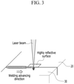
- FIG. 3 is a schematic view illustrating the coupling between a module frame and an end plate through welding in the battery module of FIG. 1 .
- the battery module 10 includes a cell stack (not illustrated) including one or more battery cells, a module frame 20 for housing the cell stack, of which a front surface 23 and a rear surface 24 facing each other are opened, and an end plate 30 that covers the front surface 23 and the rear surface 24 of the module frame 20, respectively.
- a cell stack (not illustrated) including one or more battery cells
- a module frame 20 for housing the cell stack of which a front surface 23 and a rear surface 24 facing each other are opened
- an end plate 30 that covers the front surface 23 and the rear surface 24 of the module frame 20, respectively.
- the module frame 20 may have a rectangular metal plate shape, of which the front surface 23 and the rear surface 24 are opened, and includes four edges 21 constituting the front surface 23 and four edges 22 constituting the rear surface 24.
- a coupling structure comprising: a first member and a second member which are adjacent to each other, wherein the first member and second member are weld-coupled to each other, wherein a welding part of the first member and the second member includes a first welding part formed in the first member and a second welding part formed in the second member with respect to a coupling surface of the first member and the second member, and wherein the first welding part and the second welding part have a mutually asymmetrical shape.
- a curve of a vertical cross-section of the second welding part may include a point of inflection.
- the first member may be an extruded material component or a plate material component
- the second member may be a die-casting component
- the asymmetrical shape of the first welding part and the second welding part may be defined with respect to a surface which is perpendicular to a welding advancing direction.
- the first member and the second member may have mutually different properties.
- a battery module comprising: a cell stack including a plurality of battery cells, a module frame which houses the plurality of battery cell stacks, and of which one side and the other side facing each other are opened; and an end plate coupled to the module frame through welding on one side and the other side of the module frame, wherein a welding part of the module frame and the end plate includes a first welding part formed in the module frame and a second welding part formed in the end plate, with respect to a coupling surface of the module frame and the end plate, and wherein the first welding part and the second welding part have a mutually asymmetrical shape.
- a curve of a vertical cross-section of the second welding part may include a point of inflection.
- the module frame may be an extruded material component or a plate material component, and the end plate may be a die-casting component.
- the asymmetrical shape of the first welding part and the second welding part may be defined with respect to a surface which is perpendicular to a welding advancing direction.
- the module frame may include a first joining surface formed in a part coupled to the end plate, the end plate may include a second joining surface corresponding to the first joining surface and formed in a part coupled to the module frame, and a recessed portion may be formed on at least one of the first joining surface and the second joining surface.
- the recessed portion may be recessed in a direction that is perpendicular to the first joining surface or the second joining surface.
- the recessed portion may be spaced apart from a periphery of the first joining surface or a periphery of the second joining surface.
- the end plate may further include a protrusion part located at a more central side of the end plate than the second joining surface and extending toward that the module frame.
- a method for manufacturing a battery module comprising: a step of mounting a battery cell stack including a plurality of battery cells on a module frame, of which one side and the other side facing each other are opened, and a step of coupling an end plate to the module frame on one side and the other side of the module frame, a step of coupling the module frame and the end plate uses a welding method of a Snowman wobble pattern.
- the welding method of the Snowman wobble pattern includes double wobble pattern, and a welding energy density that is applied to the module frame may be larger than a welding energy density that is applied to the end plate.
- a welding beam of the double wobble pattern that is applied to the module frame may be a circular shape, and a welding beam of the double wobble pattern that is applied to the end plate may be an elliptical shape.
- a battery pack comprising the above-mentioned battery module.
- the coupling strength can be improved by using the welding method having the double wobble pattern.
- planar when referred to as “planar”, it means when a target portion is viewed from the upper side, and when referred to as “cross-sectional”, it means when a target portion is viewed from the side of a cross section cut vertically.
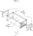
- FIG. 4 is a perspective view illustrating a battery module having a module frame according to an embodiment of the present disclosure.
- a battery module includes a module frame 500, of which one side and the other side facing each other in one direction are opened, and an end plate 150 coupled to the module frame 500 on one side and the other side of the module frame 500.
- the module frame 500 except for both sides opened in the Y-axis direction, covers a battery cell stack formed by stacking a plurality of battery cells.
- the module frame 500 may include a U-shaped frame 300 and an upper plate 400 that cover an opened upper part of the U-shaped frame 300.
- the end plate 150 may include a front surface plate 150a that covers one side of the module frame 500 and a rear surface plate 150b that covers the other side of the module frame 500.
- the front surface plate 150a and the rear surface plate 150b may be weld-coupled to each other at an edge portion that defines the opened one side and the other side of the module frame 500.
- coupling parts (CP) by welding may be formed of 10 parts in total.
- the coupling part (CP) in which the module frame 500 and the end plate 150, which have mutually different properties, are welded, may be formed by using a Snowman wobble pattern welding method.
- the physical properties may collectively refer to the electrical, magnetic, optical, mechanical, or thermal properties of a substance.
- having mutually different physical properties may mean a case having differences in surface reflectance.
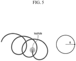
- FIG. 5 is a view illustrating a wobble pattern applied to a welding method according to a comparative example.
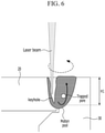
- FIG. 6 is a view illustrating a molten pool behavior when the battery module illustrated in FIG. 3 is manufactured through the welding method having the wobble pattern of FIG. 5 .
- a laser wobble pattern according to the comparative example has a pattern that repeats simply one circular shape.
- a wobble parameter of a circular shape pattern may be adjusted by a radius value R, and the circular shape pattern may be formed about one axis along a welding advancing direction.
- a molten pool according to the comparative example may have a substantially symmetrical cross-sectional structure.
- the module frame 20 according to the comparative example may be formed of a highly reflective material such as an aluminum plate material or an extruded material.
- the end plate 30 coupled to the module frame 20 through welding may be die-cast product, and a large amount of blow holes or burn through and spatters may be caused in welding beads by hydrogen and the like that are left in the die-cast product at the time of welding the die-cast product. Because a penetration depth H1 of the end plate 30, to which the welding method according to the comparative example is applied, is large, compression pores or blow holes left inside the metal of the module frame 20 or the end plate 30 may be easily caused.
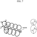
- FIG. 7 is a view illustrating the wobble pattern applied to the welding method according to the embodiment of the present disclosure.
- FIG. 8 is a view illustrating a method of manufacturing the battery module illustrated in FIG. 4 using the welding method having the wobble pattern of FIG. 7 .
- FIG. 9 is a view illustrating a molten pool behavior when the battery module illustrated in FIG. 8 is manufactured using the welding method having the wobble pattern of FIG. 8 .
- the wobble pattern applied to the welding method according to the present embodiment includes a Snowman wobble pattern.
- a key hole is formed by repeating a Snowman wobble pattern while drawing a Snowman pattern in the sequence of No. 1 to No. 9 illustrated in FIG. 7 .
- the two circular shapes have wobble parameters R 1 and R2, respectively, and the wobble parameters can be adjusted, so that energy densities of components having mutually different physical properties can be applied differently.
- the Snowman wobble pattern may have an ellipse shape as well as a circular shape
- the wobble parameter R2 has R2a and R2b
- the Snowman wobble pattern may be an ellipse shape as well as a circular shape
- the method for manufacturing a battery module includes a step of mounting a battery cell stack including a plurality of battery cells on the module frame 500, of which one side and the other side facing each other are opened, and a step of coupling the end plate 150 to the module frame 500 on one side and the other side of the module frame 500.
- the step of coupling the module frame 500 and the end plate 150 uses the Snowman wobble pattern welding method.
- the Snowman wobble pattern may include a double wobble pattern designed such that the welding energy density applied to the upper plate 400 included in the module frame 500 is larger than the welding energy density applied to the end plate 150.
- a welding beam of the double wobble pattern, which is applied to the module frame 500 may be a circular shape
- a welding beam of the double wobble pattern, which is applied to the end plate 150 may be an elliptical shape.
- wobble parameters R 1a and R 1b are identical to each other in the welding beam of the double wobble pattern, which is applied to the module frame 500
- wobble parameters R2a and R2b are different from each other in the welding beam of the double wobble pattern, which is applied to the end plate 150
- at least one of R2a and R2b may have a value that is larger than R 1a or R 1b .
- the double wobble pattern is formed in which the energy densities applied to two components having mutually different physical properties weld-coupled to each other is made different by adjusting the shapes of the welding beams to be different from each other.
- the wobble parameter of the welding beam applied to the surface of the upper plate 400 included in the highly reflective module frame 500 can be made small to increase energy density, thereby preventing weak welding due to suppression of laser beam reflection.
- the wobble parameter of the welding beam applied to the surface of the end plate 150 that is a die-cast product can be made larger to decrease energy density, thereby forming the molten pool having a small penetration depth H2 and a larger area. Accordingly, because air is easily escaped and hydrogen is prevented from flowing out in the deep part of the molten pool, the blow hole can be restrained. Further, because the double wobble pattern according to the present embodiment has a form to which weaving is added, the ability to respond to a gap or a mis-alignment between the components coupled through welding is also superior to that of the comparative example.
- the energy density is adjusted with the shape and the area of the wobble pattern by adjusting the wobble parameter, but in addition to the above, the energy density can be adjusted by adjusting the moving speed of the welding beam. In addition, the shape and the area of the wobble pattern and the moving speed of the welding beam can be adjusted at the same time, thereby adjusting the energy density.
- a welding part WP of the module frame 500 and the end plate 150 includes a first welding part WP1 formed in the module frame 500 and a second welding part WP2 formed in the end plate 150, with respect to the coupling surface of the module frame 500 and the end plate 150.
- the first welding part WP1 and the second welding part WP2 have mutually asymmetrical shapes.
- the asymmetrical shapes of the first welding part WP1 and the second welding part WP2 may be defined with respect to a surface which is perpendicular to the X-axis direction in which the welding advances.
- a curve of a vertical cross-section of the second welding part WP2 may include a point of inflection.
- the vertical cross-section of the second welding part WP2 is the vertical cross-section that is parallel to a plane YZ of the molten pool.
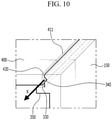
- FIG. 10 is a partial perspective view illustrating a battery module according to another embodiment of the present disclosure.
- an upper plate 400 included in a module frame includes a first joining surface 430 formed at an edge portion 411 that defines one side and the other side that are opened, respectively, and an end plate 150 includes a second joining surface 330 that is joined to the first joining surface 430.
- the module frame 500 and the end plate 150 may include metals having mutually different physical properties, and the first joining surface 430 and the second joining surface 330 may be weld-coupled to each other in order to join the module frame 500 and the end plate 150, which are formed of metals.
- a recessed portion 340 may be formed in the second joining surface 330.
- the recessed portion 340 may be recessed in a direction that is perpendicular to the second joining surface 330, and may be formed in a structure extending along the X-axis direction of FIG. 4 . That is, the recessed portion 340 may provide a passage through which gas moves between the first joining surface 430 and the second joining surface 330.
- the end plate 150 In order to manufacture the end plate 150, die-casting process may be used, and compression pores may be formed in the interior of the end plate 150 during the process.
- a blow hole phenomenon in which compression pores explode toward the outside direction of the battery module during welding may occur to reduce welding reliability when the recessed portion 340 is not formed.
- the compression pores of the interior of the metal may be guided so as to move along the X-axis direction. Accordingly, as a result, the blow hole phenomenon in which the compression pores explode toward the outside of a coupling surface of the first joining surface 430 and the second joining surface 330 can be prevented to thereby improve the welding joining force between the module frame 500 and the end plate 150.
- the recessed portion 340 is spaced apart from peripheral edges of the second joining surface 330. Among them, it is preferable that the recessed portion 340 is spaced apart from an edge located in the upper part of edges of the second joining surface 330, that is, an edge exposed to the outside of the battery module. Otherwise, because the recessed portion 340 is adjacent to the outside of the battery module, the gas moving in the space inside the recessed portion 340 may not be prevented from exploding outside.
- the end plate 150 may further include a protrusion part 350 protruding toward the module frame 500.
- the protrusion part 350 may be a shape extending along a direction parallel to the edges of the end plate 150. That is, it may be a shape which the protrusion part 350 is connected along the area in which the welding coupling of the first joining surface 430 and the second joining surface 330 are made.
- the protrusion part 350 is inserted into an opened front surface of the module frame 500, so that the module frame 500 and the end plate 150 may be coupled to each other without any misalignment. Further, because the welding advances in a state in which the first joining surface 430 and the second joining surface 330 make contact with each other without any misalignment due to the protrusion part 350, the welding may be more easily performed. Additionally, a distortion in the weld area due to the generated heat may be prevented, and even if a slight distortion occurs, a distortion or a protrusion part in the weld area may be prevented from affecting the battery cells or the devices of the interior of the module frame 500.
- FIG. 11 is a partial perspective view illustrating a battery module according to another embodiment of the present disclosure.
- the contents of the embodiments illustrated in FIG. 11 are mostly the same as those of the embodiments described in FIG. 10 , but only different parts will be described in the following.
- the recessed portion 440 may be formed in the first joining surface 430.
- the recessed portion 440 may be recessed in a direction that is perpendicular to the first joining surface 430, and may be formed in a structure extending along the X-axis direction of FIG. 4 .
- the recessed portion 440 of the present embodiment may also provide a passage through which gas moves between the first joining surface 430 and the second joining surface 330.
- the Snowman wobble pattern welding method is applied to coupling of the module frame and the end plate, but the present disclosure is not limited thereto and it may be applied to welding coupling of components having mutually different physical properties.
- the above-mentioned Snowman wobble pattern welding method may be applied to coupling of the first member and the second member through welding.
- the welding part of the first member and the second member includes a first welding part formed in the first member and a second welding part formed in the second member with respect to a coupling surface of the first member and the second member.
- first welding part and the second welding part have mutually asymmetrical shapes
- the asymmetrical shapes of the first welding part and the second welding part may be defined with respect to a surface which is perpendicular to the direction in which the welding progresses.
- a curve of a vertical cross-section of the second welding part may include a point of inflection.
- the coupling structure according to another embodiment of the present disclosure may include the first member and the second member having the same physical properties, and the above-mentioned the Snowman wobble pattern welding method may be applied to coupling of the first member and the second member through welding.
- thicknesses of the first member and the second member may be different. In the way, when the thicknesses of the first member and the second member are different, they may be weld-coupled to each other by controlling the penetration depth and the bead width according to the thickness.
- one or more of the battery modules according to the embodiment of the present disclosure can be packaged in a pack case to form a battery pack.
- the above-mentioned battery module and a battery pack may be applied to various devices. These devices may be applied to vehicles such as an electric bicycle, an electric vehicle, a hybrid vehicle, but the present disclosure is not limited thereto but can be applied to transportation means such as an electric bicycle, an electric vehicle, a hybrid vehicle, but the present disclosure is not limited thereto and can be applied to various devices that can use the cylindrical battery and the battery pack including the same, which also belongs to the scope of the present disclosure.
Landscapes
- Engineering & Computer Science (AREA)
- Optics & Photonics (AREA)
- Physics & Mathematics (AREA)
- Electrochemistry (AREA)
- General Chemical & Material Sciences (AREA)
- Chemical & Material Sciences (AREA)
- Chemical Kinetics & Catalysis (AREA)
- Plasma & Fusion (AREA)
- Mechanical Engineering (AREA)
- Manufacturing & Machinery (AREA)
- Battery Mounting, Suspending (AREA)
- Laser Beam Processing (AREA)
- Sealing Battery Cases Or Jackets (AREA)
Applications Claiming Priority (3)
| Application Number | Priority Date | Filing Date | Title |
|---|---|---|---|
| KR20190170941 | 2019-12-19 | ||
| KR1020200169335A KR102954855B1 (ko) | 2019-12-19 | 2020-12-07 | 전지 모듈 및 그 제조 방법 |
| PCT/KR2020/017827 WO2021125659A1 (fr) | 2019-12-19 | 2020-12-08 | Module de batterie et son procédé de fabrication |
Publications (2)
| Publication Number | Publication Date |
|---|---|
| EP3952015A1 true EP3952015A1 (fr) | 2022-02-09 |
| EP3952015A4 EP3952015A4 (fr) | 2023-02-22 |
Family
ID=76478474
Family Applications (1)
| Application Number | Title | Priority Date | Filing Date |
|---|---|---|---|
| EP20902921.4A Pending EP3952015A4 (fr) | 2019-12-19 | 2020-12-08 | Module de batterie et son procédé de fabrication |
Country Status (4)
| Country | Link |
|---|---|
| US (1) | US20230066980A1 (fr) |
| EP (1) | EP3952015A4 (fr) |
| JP (1) | JP7317429B2 (fr) |
| WO (1) | WO2021125659A1 (fr) |
Cited By (1)
| Publication number | Priority date | Publication date | Assignee | Title |
|---|---|---|---|---|
| EP4369488A1 (fr) * | 2022-10-24 | 2024-05-15 | SK On Co., Ltd. | Module de batterie |
Families Citing this family (3)
| Publication number | Priority date | Publication date | Assignee | Title |
|---|---|---|---|---|
| JP7703983B2 (ja) * | 2021-09-29 | 2025-07-08 | 日本ケミコン株式会社 | 溶接構造、電子部品モジュール、および溶接方法 |
| WO2023065366A1 (fr) * | 2021-10-22 | 2023-04-27 | 宁德时代新能源科技股份有限公司 | Batterie, dispositif électrique, procédé de préparation de cellule de batterie et dispositif |
| CN114639909B (zh) * | 2022-03-29 | 2024-04-19 | 远景动力技术(江苏)有限公司 | 一种电池包的壳体及其制造方法 |
Family Cites Families (21)
| Publication number | Priority date | Publication date | Assignee | Title |
|---|---|---|---|---|
| US5879416A (en) * | 1995-03-13 | 1999-03-09 | Nippondenso Co., Ltd. | Method of manufacturing battery having polygonal case |
| JPH09177974A (ja) * | 1995-12-27 | 1997-07-11 | Kobe Steel Ltd | アルミニウム又はアルミニウム合金製容器及びその製造方法 |
| JP2005040853A (ja) | 2003-07-25 | 2005-02-17 | Matsushita Electric Ind Co Ltd | レーザ溶接方法 |
| US7910855B2 (en) * | 2005-09-23 | 2011-03-22 | Lasx Industries, Inc. | No gap laser welding of coated steel |
| JP5246999B2 (ja) * | 2005-12-06 | 2013-07-24 | 三洋電機株式会社 | 密閉型電池の製造方法及び密閉型電池 |
| JP6071010B2 (ja) | 2014-01-30 | 2017-02-01 | トヨタ自動車株式会社 | 溶接方法 |
| JP6135602B2 (ja) * | 2014-06-02 | 2017-05-31 | トヨタ自動車株式会社 | 二次電池およびその製造方法 |
| JP2016087688A (ja) * | 2014-10-30 | 2016-05-23 | ヂュジィ スーベイダー マシーナリー カンパニーリミテッドZhuji Sibeida Machinery Co., Ltd | 銅と鋼との溶接方法及びその応用 |
| JP6759184B2 (ja) * | 2015-02-27 | 2020-09-23 | 三洋電機株式会社 | 電源装置及びこれを備える車両 |
| ES2887211T3 (es) * | 2015-06-19 | 2021-12-22 | Ipg Photonics Corp | Sistema de soldadura láser con un cabezal de soldadura láser dotado de espejos móviles duales que proporcionan movimiento de haz con campo de visión limitado |
| KR102058689B1 (ko) * | 2015-09-22 | 2019-12-23 | 주식회사 엘지화학 | 배터리 모듈, 이러한 배터리 모듈을 포함하는 배터리 팩 및 이러한 배터리 팩을 포함하는 자동차 |
| KR20180081921A (ko) * | 2017-01-09 | 2018-07-18 | 에이치엘그린파워 주식회사 | 배터리 모듈 하우징 구조 |
| DE102017211982B4 (de) * | 2017-07-13 | 2019-04-18 | Trumpf Laser- Und Systemtechnik Gmbh | Verfahren und Vorrichtung zum Fügen von mindestens zwei Werkstücken |
| CN107414293A (zh) * | 2017-08-03 | 2017-12-01 | 大族激光科技产业集团股份有限公司 | 一种周期摆动激光焊接方法及焊接组件 |
| JP6948888B2 (ja) * | 2017-08-31 | 2021-10-13 | 株式会社神戸製鋼所 | 接合体の製造方法及び接合体の製造装置 |
| CN107755912B (zh) | 2017-10-26 | 2019-08-30 | 重庆科技学院 | 管材全位置激光-电弧复合焊接系统 |
| JP6871135B2 (ja) * | 2017-11-14 | 2021-05-12 | トヨタ自動車株式会社 | 平角線のレーザ溶接方法 |
| DE102017126867A1 (de) | 2017-11-15 | 2019-05-16 | Precitec Gmbh & Co. Kg | Laserbearbeitungssystem und Verfahren zur Laserbearbeitung |
| KR102203250B1 (ko) * | 2017-11-29 | 2021-01-13 | 주식회사 엘지화학 | 엔드 프레임을 구비한 배터리 모듈 |
| JP7264717B2 (ja) * | 2019-05-15 | 2023-04-25 | ファナック株式会社 | ステータコアの端面に固定されるハウジングを備える電動機 |
| KR102910427B1 (ko) * | 2021-01-25 | 2026-01-13 | 에스케이온 주식회사 | 배터리 모듈 |
-
2020
- 2020-12-08 US US17/785,710 patent/US20230066980A1/en active Pending
- 2020-12-08 WO PCT/KR2020/017827 patent/WO2021125659A1/fr not_active Ceased
- 2020-12-08 EP EP20902921.4A patent/EP3952015A4/fr active Pending
- 2020-12-08 JP JP2021560879A patent/JP7317429B2/ja active Active
Cited By (2)
| Publication number | Priority date | Publication date | Assignee | Title |
|---|---|---|---|---|
| EP4369488A1 (fr) * | 2022-10-24 | 2024-05-15 | SK On Co., Ltd. | Module de batterie |
| US12057594B2 (en) | 2022-10-24 | 2024-08-06 | Sk On Co., Ltd. | Battery module |
Also Published As
| Publication number | Publication date |
|---|---|
| JP7317429B2 (ja) | 2023-07-31 |
| WO2021125659A1 (fr) | 2021-06-24 |
| EP3952015A4 (fr) | 2023-02-22 |
| JP2022529258A (ja) | 2022-06-20 |
| US20230066980A1 (en) | 2023-03-02 |
Similar Documents
| Publication | Publication Date | Title |
|---|---|---|
| EP3952015A1 (fr) | Module de batterie et son procédé de fabrication | |
| EP4184683B1 (fr) | Module de batterie et bloc-batterie le comprenant | |
| JP7416518B2 (ja) | 電池モジュールおよびこれを含む電池パック | |
| EP3971925B1 (fr) | Module de batterie et bloc-batterie le comprenant | |
| JP2022522369A (ja) | 保護板、電池セル組立体、電池モジュール及び車両 | |
| KR102925164B1 (ko) | 개선된 안전성과 조립성을 갖는 배터리 모듈 | |
| KR101223522B1 (ko) | 이차전지 | |
| EP4007024A1 (fr) | Batterie secondaire et dispositif la comprenant | |
| US12555839B2 (en) | Battery module, battery pack including the same, and method of manufacturing battery module | |
| CN113710406B (zh) | 电池模块和制造该电池模块的方法 | |
| KR102954855B1 (ko) | 전지 모듈 및 그 제조 방법 | |
| KR20210037453A (ko) | 전지 모듈, 이의 제조 방법 및 전지팩 | |
| US12597660B2 (en) | Battery module and method of manufacturing the same | |
| EP4697473A1 (fr) | Module de batterie et bloc-batterie le comprenant | |
| EP4362196B1 (fr) | Élément de batterie et module de batterie le comprenant | |
| KR102754503B1 (ko) | 전지 모듈 및 이를 포함하는 디바이스 | |
| US20250030116A1 (en) | Battery Pack and Device Including the Same | |
| KR20210126514A (ko) | 전지 모듈 및 그 제조 방법 | |
| EP4203171A1 (fr) | Module de batterie et bloc-batterie le comprenant |
Legal Events
| Date | Code | Title | Description |
|---|---|---|---|
| STAA | Information on the status of an ep patent application or granted ep patent |
Free format text: STATUS: THE INTERNATIONAL PUBLICATION HAS BEEN MADE |
|
| PUAI | Public reference made under article 153(3) epc to a published international application that has entered the european phase |
Free format text: ORIGINAL CODE: 0009012 |
|
| STAA | Information on the status of an ep patent application or granted ep patent |
Free format text: STATUS: REQUEST FOR EXAMINATION WAS MADE |
|
| 17P | Request for examination filed |
Effective date: 20211028 |
|
| AK | Designated contracting states |
Kind code of ref document: A1 Designated state(s): AL AT BE BG CH CY CZ DE DK EE ES FI FR GB GR HR HU IE IS IT LI LT LU LV MC MK MT NL NO PL PT RO RS SE SI SK SM TR |
|
| RAP3 | Party data changed (applicant data changed or rights of an application transferred) |
Owner name: LG ENERGY SOLUTION, LTD. |
|
| RIC1 | Information provided on ipc code assigned before grant |
Ipc: B23K 101/36 20060101ALI20220902BHEP Ipc: B23K 26/21 20140101ALI20220902BHEP Ipc: B23K 26/00 20140101ALI20220902BHEP Ipc: H01M 50/20 20210101AFI20220902BHEP |
|
| A4 | Supplementary search report drawn up and despatched |
Effective date: 20230123 |
|
| RIC1 | Information provided on ipc code assigned before grant |
Ipc: B23K 101/36 20060101ALI20230117BHEP Ipc: B23K 26/21 20140101ALI20230117BHEP Ipc: B23K 26/00 20060101ALI20230117BHEP Ipc: H01M 50/20 20210101AFI20230117BHEP |
|
| DAV | Request for validation of the european patent (deleted) | ||
| DAX | Request for extension of the european patent (deleted) |