EP3952076A1 - Procédé d'imprégnation par dégouttage du stator ou de l'ancrage d'une machine électrique - Google Patents
Procédé d'imprégnation par dégouttage du stator ou de l'ancrage d'une machine électrique Download PDFInfo
- Publication number
- EP3952076A1 EP3952076A1 EP21199146.8A EP21199146A EP3952076A1 EP 3952076 A1 EP3952076 A1 EP 3952076A1 EP 21199146 A EP21199146 A EP 21199146A EP 3952076 A1 EP3952076 A1 EP 3952076A1
- Authority
- EP
- European Patent Office
- Prior art keywords
- stator
- armature
- inductor
- temperature
- synthetic resin
- Prior art date
- Legal status (The legal status is an assumption and is not a legal conclusion. Google has not performed a legal analysis and makes no representation as to the accuracy of the status listed.)
- Withdrawn
Links
- 238000000034 method Methods 0.000 title claims abstract description 54
- 238000005470 impregnation Methods 0.000 title claims abstract description 31
- 239000000057 synthetic resin Substances 0.000 claims abstract description 56
- 229920003002 synthetic resin Polymers 0.000 claims abstract description 56
- 238000010438 heat treatment Methods 0.000 claims abstract description 39
- 239000007788 liquid Substances 0.000 claims abstract description 19
- 238000001816 cooling Methods 0.000 claims abstract description 4
- 238000004804 winding Methods 0.000 claims description 30
- 230000008569 process Effects 0.000 claims description 16
- 238000013459 approach Methods 0.000 claims description 3
- 230000001965 increasing effect Effects 0.000 claims description 3
- 239000004848 polyfunctional curative Substances 0.000 description 7
- 238000004519 manufacturing process Methods 0.000 description 6
- 230000001939 inductive effect Effects 0.000 description 4
- 230000004323 axial length Effects 0.000 description 3
- 239000000203 mixture Substances 0.000 description 3
- 229920005989 resin Polymers 0.000 description 3
- 239000011347 resin Substances 0.000 description 3
- 229920000965 Duroplast Polymers 0.000 description 2
- 239000004638 Duroplast Substances 0.000 description 2
- 230000001419 dependent effect Effects 0.000 description 2
- 238000010586 diagram Methods 0.000 description 2
- 230000005484 gravity Effects 0.000 description 2
- 239000012774 insulation material Substances 0.000 description 2
- 239000000463 material Substances 0.000 description 2
- 229920001187 thermosetting polymer Polymers 0.000 description 2
- XEEYBQQBJWHFJM-UHFFFAOYSA-N Iron Chemical group [Fe] XEEYBQQBJWHFJM-UHFFFAOYSA-N 0.000 description 1
- 230000001133 acceleration Effects 0.000 description 1
- 230000009471 action Effects 0.000 description 1
- 230000004913 activation Effects 0.000 description 1
- 230000033228 biological regulation Effects 0.000 description 1
- 238000009529 body temperature measurement Methods 0.000 description 1
- 239000002826 coolant Substances 0.000 description 1
- 238000011161 development Methods 0.000 description 1
- 230000018109 developmental process Effects 0.000 description 1
- 238000006073 displacement reaction Methods 0.000 description 1
- 238000009826 distribution Methods 0.000 description 1
- 238000005485 electric heating Methods 0.000 description 1
- 238000010292 electrical insulation Methods 0.000 description 1
- 239000012777 electrically insulating material Substances 0.000 description 1
- 238000005516 engineering process Methods 0.000 description 1
- 230000001771 impaired effect Effects 0.000 description 1
- 230000006698 induction Effects 0.000 description 1
- 238000009434 installation Methods 0.000 description 1
- 239000011810 insulating material Substances 0.000 description 1
- 238000003475 lamination Methods 0.000 description 1
- 238000012423 maintenance Methods 0.000 description 1
- 238000005259 measurement Methods 0.000 description 1
- 239000002184 metal Substances 0.000 description 1
- 229910052751 metal Inorganic materials 0.000 description 1
- 238000013021 overheating Methods 0.000 description 1
- 230000035515 penetration Effects 0.000 description 1
- 230000005855 radiation Effects 0.000 description 1
- 230000009467 reduction Effects 0.000 description 1
- 230000001105 regulatory effect Effects 0.000 description 1
Images
Classifications
-
- H—ELECTRICITY
- H02—GENERATION; CONVERSION OR DISTRIBUTION OF ELECTRIC POWER
- H02K—DYNAMO-ELECTRIC MACHINES
- H02K15/00—Processes or apparatus specially adapted for manufacturing, assembling, maintaining or repairing of dynamo-electric machines
- H02K15/12—Impregnating, moulding insulation, heating or drying of windings, stators, rotors or machines
- H02K15/125—Heating or drying of machines in operational state, e.g. standstill heating
-
- H—ELECTRICITY
- H02—GENERATION; CONVERSION OR DISTRIBUTION OF ELECTRIC POWER
- H02K—DYNAMO-ELECTRIC MACHINES
- H02K15/00—Processes or apparatus specially adapted for manufacturing, assembling, maintaining or repairing of dynamo-electric machines
- H02K15/12—Impregnating, moulding insulation, heating or drying of windings, stators, rotors or machines
-
- H—ELECTRICITY
- H05—ELECTRIC TECHNIQUES NOT OTHERWISE PROVIDED FOR
- H05B—ELECTRIC HEATING; ELECTRIC LIGHT SOURCES NOT OTHERWISE PROVIDED FOR; CIRCUIT ARRANGEMENTS FOR ELECTRIC LIGHT SOURCES, IN GENERAL
- H05B6/00—Heating by electric, magnetic or electromagnetic fields
- H05B6/02—Induction heating
- H05B6/06—Control, e.g. of temperature, of power
-
- H—ELECTRICITY
- H05—ELECTRIC TECHNIQUES NOT OTHERWISE PROVIDED FOR
- H05B—ELECTRIC HEATING; ELECTRIC LIGHT SOURCES NOT OTHERWISE PROVIDED FOR; CIRCUIT ARRANGEMENTS FOR ELECTRIC LIGHT SOURCES, IN GENERAL
- H05B6/00—Heating by electric, magnetic or electromagnetic fields
- H05B6/02—Induction heating
- H05B6/10—Induction heating apparatus, other than furnaces, for specific applications
-
- H—ELECTRICITY
- H05—ELECTRIC TECHNIQUES NOT OTHERWISE PROVIDED FOR
- H05B—ELECTRIC HEATING; ELECTRIC LIGHT SOURCES NOT OTHERWISE PROVIDED FOR; CIRCUIT ARRANGEMENTS FOR ELECTRIC LIGHT SOURCES, IN GENERAL
- H05B6/00—Heating by electric, magnetic or electromagnetic fields
- H05B6/02—Induction heating
- H05B6/10—Induction heating apparatus, other than furnaces, for specific applications
- H05B6/105—Induction heating apparatus, other than furnaces, for specific applications using a susceptor
Definitions
- the invention relates to a method for trickle impregnation of the stator or armature of an electric machine with a synthetic resin that hardens when the temperature is increased.
- stator and armature In the manufacture of an electric machine, be it an electric motor or a generator, the windings of the stator and armature must be hardened. This is usually done today by means of a so-called trickling process and a related impregnation device.
- the stator or the armature is heated for this purpose and clamped in the impregnation device at an angle with respect to its longitudinal axis and rotated about this longitudinal axis.
- the stator or armature can also be aligned horizontally.
- a synthetic resin that is initially liquid at room temperature is then preferably dripped onto the higher axial end of the stator or armature, for example onto its end winding.
- the synthetic resin can consist of one or more components, for example a base synthetic resin and a hardener.
- the volume flow with which the still liquid synthetic resin is applied to the stator or armature is tailored to the respective capacity of the same. After the dripping, the synthetic resin gets into the gaps between the winding wires and the laminated cores and completely fills these gaps. When the stator or armature is subsequently heated to a curing temperature of the synthetic resin, the latter hardens and becomes a duroplastic which, after this curing, can no longer be deformed by renewed heating. As a result, the components of the stator or armature that have come into contact with the synthetic resin are firmly connected to one another. The duroplast meets all mechanical and electrical requirements that are placed on a stationary or rotating electrical machine.
- the stator or armature is at least before the beginning of the Heated trickling process to a so-called trickling temperature and kept at this temperature during the trickling process.
- the trickling temperature can be between 70°C and 90°C, for example.
- the stator or armature can be heated to the trickling temperature and the curing temperature in a suitable oven. From the DE 1 212 204 A and the DE 19 19 642 A However, it is already known to heat the stator or armature by means of an electrical heating current which is passed through the windings of the stator or armature. Since simply passing a heating current through the windings causes the achievable actual temperatures to deviate too much from the desired setpoint temperatures, it was proposed to ensure that the desired temperatures are reached and maintained by regulating the heating current. Here was used the knowledge that the ohmic resistance in a winding increases with increasing temperature, so that the ohmic resistance can be used to determine the temperature of the winding.
- JP 2010 262828 A , DE 15 38 918 A1 and JP 2005 086954 A show methods for trickle impregnation with features of the preamble of claim 1.
- a disadvantage of these known methods and the devices used for impregnating a stator or armature of an electric machine is that the temperature is controlled by means of a heating current conducted through the winding, which is technically complicated to feed into the rotating stator or armature.
- the methods and devices proposed in the two documents have the shortcoming that the regulation of the heating current is based solely on the temperature of the winding through which the heating current flows. This is disadvantageous at least in those periods in which the surrounding the windings other components have not yet reached the temperature of the windings.
- the synthetic resin since the synthetic resin not only comes into contact between adjacent wires or wire sections of the windings but also with other components of the stator or armature, the temperature for the synthetic resin present there is not exactly known.
- At least the heating-up phase until the trickling temperature is reached should be extended until it can be assumed that the winding temperature determined by the electrical resistance measurement is also present in all other components of the stator or armature. Only then can the synthetic resin be poured into the stator or armature with the desired process reliability. Since this uncertainty regarding the temperatures of the components of the stator or armature and the synthetic resin also exists at the beginning of the curing process, it must also be disadvantageously extended by a safety period. Ultimately, it is judged to be unfavorable that the heating of the synthetic resin takes place only indirectly through the heat transport between the windings and the same. This means that it takes a comparatively long time to reach the trickling temperature and the curing temperature.
- the invention is therefore based on the object of presenting a method with which the impregnation of a stator or an armature of an electric machine with a synthetic resin that hardens under the action of heat can be carried out more quickly, more energy-efficiently and more cost-effectively than before.
- this method provides for the stator or armature to be heated inductively.
- the average speed at which the inductor is reciprocated is, for example, 5 to 50 millimeters per second, including the range limits.
- the stator or armature is preferably arranged in an impregnation device in which it can be inclined with respect to its longitudinal axis to the horizontal and can be rotated about this longitudinal axis.
- the inclination encourages the synthetic resin to flow into the stator or armature.
- Rotation of the stator or armature can improve uniform heating thereof during induction heating and prevent unfavorable resin build-up on the underside of the stator or armature.
- the invention utilizes the knowledge that a stator or armature for an electric machine can very advantageously be brought to the trickling temperature and the hardening temperature by means of inductive heating and can be kept at these temperatures. It is of particular importance that with only one inductor, eddy currents are generated simultaneously in all electrically conductive components of such a stator or armature, which heat these components at the same time. As a result, the heating-up time and the required electrical energy are significantly reduced compared to the known impregnation methods. As a result, the manufacturing costs for the impregnation are reduced.
- the inductor surrounds the stator or armature radially on the outside in a ring-shaped or hollow-cylindrical manner.
- the inductor it is also possible for the inductor to be arranged in a central, coaxial cavity of the stator.
- the electrical eddy currents heat up all electrically conductive components of the stator or armature at the same time, namely the iron core frame, the laminations of the core, the winding wires and, via heat conduction, also the synthetic resin that has been instilled.
- Other components or objects e.g. insulation material
- This desired trickling temperature or curing temperature is also indirectly affected by this desired trickling temperature or curing temperature.
- the inductor is moved back and forth coaxially to the longitudinal axis of the stator or armature between at least two positions spaced apart axially. These two positions are defined, for example, by the two axial ends of the stator or armature.
- the described movement of the inductor between the two axial end positions makes it possible to build the inductor in an advantageous axially short manner.
- by moving the inductor back and forth it is advantageously achieved that axial sections of the stator or armature are only occasionally swept by the alternating magnetic field of the inductor.
- the components of the stator or armature that are not covered by the inductor can give off part of the thermal energy they received shortly beforehand to neighboring components.
- a further measure for rapid and damage-free heating of the stator or armature is preferably that the inductor is switched on and off alternately while maintaining a time interval in order to reach and/or maintain a predetermined temperature, i.e. the trickling temperature and the curing temperature.
- the inductor is switched on when a target temperature of the stator or armature has not yet been reached, while the inductor is switched off when the respective target temperature has been reached.
- the target temperature can definitely be slightly above the trickling temperature or above the curing temperature, since the subsequent switch-off and the short waiting phase that follows lead to cooling.
- the respective setpoint temperature can have a value, particularly during the heating-up phases, which is dependent on the time that has elapsed.
- the outside temperature of the stator is preferably measured without contact during method steps a) to d), for example with a temperature sensor suitable for this purpose.
- This non-contact temperature measurement is advantageous because of the rotation of the stator or armature during the trickling process and the curing process, because it means that no stationary temperature sensors need to be attached to the stator or armature and their signals fed out of the rotating system.
- the non-contact temperature sensor is preferably connected to a control device in which the measured temperature values are further processed.
- the control device switches the inductor on or off depending on whether previously specified target temperatures are reached or exceeded or fallen below. After switching off the inductor, heat is both radiated outwards and released inwards by the stator or armature. This heats up the interior of the stator or armature and thus everyone there arranged isolating components as well as the instilled mixture of synthetic resin and hardener.
- the process of temperature-controlled switching on and off of the inductor with the waiting phase to be observed in between is repeated until the entire stator or armature has reached the desired trickling temperature or curing temperature.
- the process described is preferably used to maintain the trickling temperature or curing temperature once reached, or a trickling temperature range or curing temperature range, over a specific period of time.
- the synthetic resin which is still liquid, is dripped onto the axially outer and higher end of the winding of the stator or armature.
- the angle of inclination of the stator or armature is, for example, 5° to 20° to the horizontal, including the range limits. This allows the resin to easily penetrate into the interior of the stator or armature by gravity.
- stator or armature is placed horizontally in order to prevent the synthetic resin from leaking out of it.
- the temperature of the stator or armature is 80° C. to 130° C. in a preferred trickling temperature range, and in a curing temperature range of 140°C to 170°C, including the respective range limits.
- the stator or armature is rotated about its longitudinal axis at a speed of, for example, 5 to 40 revolutions per minute in order to achieve an even distribution of the synthetic resin.
- speed specifications also include the range limits.
- the speed control of the actuator is such that the average dwell time of an electromagnetically active inductor in all areas of the stator or armature is approximately the same over a predetermined period of time is long.
- the inductor is in operation when it approaches an axial end of the stator or armature, but that the inductor is switched off when it reaches this end, and that the inductor is only put back into operation when it has reached this end region of the stator or armature by a predetermined distance.
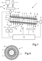
- FIG. 1 shows 1 overall an impregnation device 1 for a hollow-cylindrical stator 2 shown in a schematic longitudinal section.
- a treated in the impregnation device 1 stator 2 is intended after its final completion for installation in an electric machine.
- the stator 2 has, for example, a conventional structure with stator segments arranged in a ring, each of these stator segments having a frame 3 to which metal sheets arranged one behind the other are fastened.
- Stator windings 4 constructed from wires or by means of the known hairpin technology are arranged between adjacent stator segments, the line ends of which lead to an axially end-side End windings 17 are brought out.
- insulating material (not shown) is arranged in the stator 2, by means of which components that are to be electrically separated from one another are spaced apart.
- the stator 2 is accommodated in the impregnation device 1 not shown in detail with respect to its longitudinal axis 15 at an angle of inclination ⁇ to the horizontal 16, the angle of inclination being 5° to 20° in the exemplary embodiment shown. As mentioned at the beginning, the angle of inclination can also be 0°.
- the stator 2 can be tilted by means of a pivoting device, not shown.
- a related pivoting movement 25 is in 1 indicated by a double arrow.
- the stator 2 is in the in 1 shown embodiment in the impregnation device 1 also rotatably mounted and driven by an electric drive motor 12 about its longitudinal axis 15.
- the drive motor 12 is connected to a control device 19 of the device via a control line, which is not designated but is shown in dashed lines.
- the stator 2 is surrounded coaxially in a ring shape over a comparatively short section by an inductor 6 which is largely designed as an electrical coil.
- the inductor 6 consists of a helically bent tube 20 through which a coolant can be guided. Clear the axial length of the inductor 6 is shorter than the axial length of the stator 2.
- the inductor 6 is connected via flexible lines 21, 22 to a voltage source 23 which operates as a frequency converter and can generate an AC voltage of the desired frequency.
- a voltage source 23 which operates as a frequency converter and can generate an AC voltage of the desired frequency.
- an alternating current flows through the material of the helical tube 20 and generates an alternating magnetic field, which generates eddy currents in all electrically conductive components of the stator 2, which heat up these components at the same time.
- Adjacent, electrically insulating materials of the stator 2 are also heated by thermal radiation or thermal conduction.
- the inductor 6 is arranged to be displaceable coaxially to the stator 2 by means of an actuator 13 .
- This actuator 13 is connected to the control device 19 via a control line drawn in dashed lines.
- the inductor 6 can be moved back and forth between a first axial end position A and a second axial end position by means of the actuator 13 . These directions of movement 18 of the inductor 6 are illustrated by a double arrow. In 1 the inductor 6' is shown in the second end position B with a dotted line.
- a temperature sensor 14 is also present, with which the surface temperature of the stator 2 can be measured. The temperature is measured without contact, and the temperature sensor 14 is connected to the control device 19 via a sensor line shown in dashed lines.
- the impregnation device 1 also includes a trickling device 24 shown here as an example, which includes a first container 10 for a synthetic resin 5 that is liquid at room temperature and a second container 11 for a liquid hardener. Synthetic resin and hardener are fed into a mixing container 9 in a predetermined quantity ratio via valves that are not designated further.
- the synthetic resin 5 is conveyed from the mixing container 9 by means of a pump 8 to at least one trickling nozzle 7, with which the synthetic resin 5 can be trickled onto the end winding 17 of the stator 2 with a comparatively low volume flow.
- the volume flow is so large that just as much of the synthetic resin 5 reaches the end winding 17 as can be accommodated by the stator 2 to fill its cavities.
- a one-component synthetic resin can also be used, which also hardens to form a duroplastic when the temperature increases.
- the second container 11, the second valve and the mixing container 9 can be omitted.
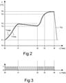
- FIG. 1 illustrates the profile T(t) of the temperature T of the stator 2 over time t during trickle impregnation of the same with the impregnation device 1 according to FIG 1 .
- the temperature T1 of the stator 2 is identical to the ambient room temperature.
- the drive motor 12 and the actuator 13 of the Control device 19 switched on.
- the stator 2 rotates about its longitudinal axis 15, and the actuator 13, which can be designed, for example, as a pneumatic piston-cylinder arrangement or as an electric actuator, pushes the inductor 6 between the two axial end positions A and B back and forth.
- the inductor 6 By switching on the voltage source 23 using the control device 19, the inductor 6 is put into operation with regard to its electromagnetic function, so that an electrical alternating current with a predetermined frequency flows through the flexible power lines 21, 22 and the helical tube 20 of the inductor 6. As a result, an alternating magnetic field is generated by the inductor 6, which induces eddy currents in all electrically conductive components of the stator 2, which leads to heating of the same and also indirectly to neighboring, non-electrically conductive components of the stator 2.
- stator 2 or armature For the inductive heating of the stator 2 or armature, it is not absolutely necessary for the stator 2 to rotate about its longitudinal axis 15 during the operation of the inductor 6 . However, this rotation is advantageous if the inductor 6 has an uneven structure that differs from a homogeneous coil. In addition, the rotation of the stator 2 or armature ensures that the not yet gelled or not yet solidified synthetic resin 5 collects in the lower region of the stator 2 or armature as a result of gravity and consequently escapes axially from the same unintentionally.
- the inductor 6 Since the inductor 6 has a comparatively small axial length compared to the stator 2 and is constantly moved back and forth between the two axial end positions A, B by the actuator 13, a largely uniform heating of all components of the stator 2 can be achieved. If the inductor 6 has left this location in the direction of the second axial end section after a heat treatment of the first axial end section of the stator 2, the heat present at the first end section of the stator 2 can be passed on to all the components there, so that electrically not conductive components of the stator 2 are heated comparatively evenly together with the electrically conductive components.
- the dwell time of an electromagnetically active inductor 6 in the area of the axial ends of the stator 2 is reduced by means of a speed control of the actuator 13 adapted thereto 6 is approximately the same in all areas of the stator 2.
- Another possibility for achieving an axially uniform heating of the stator 2 is to not have the inductor 6 in the area of the two axial ends of the stator 2 constantly in operation. For example, it can be provided that the inductor 6 is still in operation when it approaches an axial end of the stator 2, but is switched off when it is reached, and that the inductor 6 is then put back into operation when it reaches this end region of the stator 2 by a predetermined distance.
- the inductor 6 is operated in such a way that, starting from the initial temperature T1, the stator 2 is inductively heated. Which happens how 3 illustrated, for example by means of an alternating switching on and off of the inductor 6, wherein in 3 the switched-on state of the inductor 6 is identified by the number 1 and the switched-off state by the number 0.
- the inductor 6 is preferably switched on and off in a controlled manner, depending on the outside temperature of the stator 2 measured by the temperature sensor 14
- T-high has exceeded, the inductor 6 is switched off briefly. If the temperature falls below a lower target value T-low, the inductor 6 is switched on again.
- These setpoint temperature values can be defined as a function of the time t that has already elapsed. 2 shows that the outside temperature T of the stator 2 is always in a temperature range due to the control described, which is limited by the curves for the lower target temperature value T-low and the upper target temperature value T-high.
- the outside temperature T of the stator and thus also its inside temperature has calculated a temperature value which is in a so-called trickling temperature range T2-T3.
- the control of the impregnation device 1 ensures that the temperature T of the stator 2 remains within this trickling temperature range T2-T3 during the trickling phase that now follows in a second time period t1-t2. This is done by switching the inductor 6 on and off and moving it back and forth coaxially to the stator 2 Inside the stator 2 supplied.
- the synthetic resin 5 is distributed evenly in the stator 2 and thus fills out all of the previously air-filled intermediate spaces.
- the stator 2 or armature is placed horizontally in order to during the now following heating-up phase Curing temperature (T2 - T3) to avoid leakage of the synthetic resin 5 from the stator 2.
- the inductor 6 can be switched off, provided that the lower temperature limit T2 of the trickling temperature range T2 - T3 is not undershot. This can, for example, be advantageous for further energy savings in the case of small stators or armatures and comparatively short trickling periods.
- a third time period t2-t3 begins, in which the stator 2 is inductively heated by the inductor 6 to a curing temperature which is in a previously specified curing temperature range T4-T5.
- a largely identical and constant internal and external temperature of the stator 2 is achieved by constantly moving the inductor 6 back and forth and switching it on and off in a temperature-controlled manner.
- the inductor 6 and the actuator 13 are switched off and the stator 2 is removed from the impregnation device 1 and temporarily stored to cool down to room temperature T1.
- the method presented for trickle impregnation of a stator 2 or armature of an electric machine is characterized by its simple controllability and rapid and homogeneous heating of the stator 2 or armature. In comparison to known methods, it enables all components of the stator 2 or armature to be heated at the same time, without the risk of thermally less stable components, such as insulation materials, burning up due to overheating or at least having their desired properties impaired.
- the inductive heating of the stator 2 or armature is much more energy-efficient because of its thermally higher efficiency than heating the same in a heating furnace or by means of an electric heating current that is passed through the winding of the stator or armature, because in the latter case only the Winding lines for heating the stator or armature, while in the case of inductive heating of the same all electrically conductive components are heated at the same time.
- none of the winding wires need to be connected to an electrical voltage source and supplied with a heating current, so that the assembly process in the impregnation device 1 is significantly reduced compared to the heating current method. Overall, the advantages mentioned result in a significant reduction in production time and thus in manufacturing costs.
- FIG. 4 shows that the method according to the invention for trickle impregnation can also be applied to a stator 2 to heat from radially inside.
- an inductor 6 * embodied helically, for example, is arranged coaxially in a cylindrical cavity 26 of the stator 2 . If required, this inductor 6* can also be moved back and forth axially and its activation can be controlled as described. All components of the stator 2 are then heated as already explained.
Landscapes
- Physics & Mathematics (AREA)
- Electromagnetism (AREA)
- Engineering & Computer Science (AREA)
- Manufacturing & Machinery (AREA)
- Power Engineering (AREA)
- Manufacture Of Motors, Generators (AREA)
Applications Claiming Priority (3)
| Application Number | Priority Date | Filing Date | Title |
|---|---|---|---|
| DE102017001940.1A DE102017001940A1 (de) | 2017-02-28 | 2017-02-28 | Verfahren zur Träufelimprägnierung des Stators oder Ankers einer Elektromaschine |
| EP18717204.4A EP3590180B1 (fr) | 2017-02-28 | 2018-02-18 | Procédé d'imprégnation goutte à goutte du stator ou de l'induit d'un moteur électrique |
| PCT/DE2018/000033 WO2018157876A1 (fr) | 2017-02-28 | 2018-02-18 | Procédé d'imprégnation goutte à goutte du stator ou de l'induit d'un moteur électrique |
Related Parent Applications (1)
| Application Number | Title | Priority Date | Filing Date |
|---|---|---|---|
| EP18717204.4A Division EP3590180B1 (fr) | 2017-02-28 | 2018-02-18 | Procédé d'imprégnation goutte à goutte du stator ou de l'induit d'un moteur électrique |
Publications (1)
| Publication Number | Publication Date |
|---|---|
| EP3952076A1 true EP3952076A1 (fr) | 2022-02-09 |
Family
ID=61965651
Family Applications (2)
| Application Number | Title | Priority Date | Filing Date |
|---|---|---|---|
| EP21199146.8A Withdrawn EP3952076A1 (fr) | 2017-02-28 | 2018-02-18 | Procédé d'imprégnation par dégouttage du stator ou de l'ancrage d'une machine électrique |
| EP18717204.4A Active EP3590180B1 (fr) | 2017-02-28 | 2018-02-18 | Procédé d'imprégnation goutte à goutte du stator ou de l'induit d'un moteur électrique |
Family Applications After (1)
| Application Number | Title | Priority Date | Filing Date |
|---|---|---|---|
| EP18717204.4A Active EP3590180B1 (fr) | 2017-02-28 | 2018-02-18 | Procédé d'imprégnation goutte à goutte du stator ou de l'induit d'un moteur électrique |
Country Status (6)
| Country | Link |
|---|---|
| US (1) | US11611270B2 (fr) |
| EP (2) | EP3952076A1 (fr) |
| KR (1) | KR20190127759A (fr) |
| CN (1) | CN110603721B (fr) |
| DE (1) | DE102017001940A1 (fr) |
| WO (1) | WO2018157876A1 (fr) |
Families Citing this family (4)
| Publication number | Priority date | Publication date | Assignee | Title |
|---|---|---|---|---|
| DE102019106392A1 (de) * | 2019-03-13 | 2020-09-17 | Grob-Werke Gmbh & Co. Kg | Vorrichtung und Verfahren zum Imprägnieren von Bauteilen einer elektrischen Maschine |
| CN110719005A (zh) * | 2019-10-24 | 2020-01-21 | 宁德特波电机有限公司 | 不锈钢电机灌封工艺 |
| US11588385B2 (en) * | 2020-10-30 | 2023-02-21 | GM Global Technology Operations LLC | Method for gel curing a varnish of a stator assembly |
| DE102024107995A1 (de) * | 2024-03-20 | 2025-09-25 | Audi Aktiengesellschaft | Verfahren zum Herstellen eines Bauteils für eine elektrische Maschine sowie entsprechende Vorrichtung zur Herstellung des Bauteils |
Citations (5)
| Publication number | Priority date | Publication date | Assignee | Title |
|---|---|---|---|---|
| DE1212204B (de) | 1964-08-21 | 1966-03-10 | Elektrotechnik M B H Ges | Verfahren zum Impraegnieren von Ein- und Mehrphasen-Statorwicklungen sowie Vorrichtung zur Ausuebung des Verfahrens |
| DE1919642A1 (de) | 1969-04-18 | 1970-11-05 | Veser F | Geraet und Verfahren zur Stromsteuerung fuer Anlagen zur Traeufelimpraegnierung von Wicklungen elektrischer Maschinen |
| DE1538918A1 (de) | 1966-10-27 | 1970-11-12 | Licentia Gmbh | Verfahren zum Impraegnieren von Wicklungen |
| JP2005086954A (ja) | 2003-09-10 | 2005-03-31 | Aisin Aw Co Ltd | 回転電機巻線コイルの加熱処理装置 |
| JP2010262828A (ja) | 2009-05-07 | 2010-11-18 | Hitachi Chem Co Ltd | 誘導加熱コイル、誘導加熱装置及び電気絶縁処理システム |
Family Cites Families (9)
| Publication number | Priority date | Publication date | Assignee | Title |
|---|---|---|---|---|
| CA803967A (en) * | 1969-01-14 | General Electric Company | Treating apparatus and method | |
| US5474799A (en) | 1992-10-13 | 1995-12-12 | Reliance Electric Industrial Company | Apparatus and method for coating an electromagnetic coil |
| US5919308A (en) * | 1996-06-04 | 1999-07-06 | Axis Usa, Inc. | Conveyance of dynamo-electric machine components in resin application systems |
| US6302961B1 (en) | 1999-07-12 | 2001-10-16 | Ennis Automotive, Inc. | Apparatus for applying a liquid coating to electrical components |
| JP4706643B2 (ja) | 2007-02-08 | 2011-06-22 | トヨタ自動車株式会社 | 固定子の加熱方法、及び加熱装置 |
| DE102009045200B4 (de) | 2009-09-30 | 2021-02-11 | Inter-Consult Gmbh | Verfahren und Vorrichtung zum Bearbeiten von Bauteilen elektrischer Maschinen |
| JP5444134B2 (ja) | 2010-06-18 | 2014-03-19 | 東京電力株式会社 | 誘導加熱による固定子の加熱方法、及び加熱装置 |
| DE112014002790T5 (de) * | 2013-08-02 | 2016-03-17 | Aisin Aw Co., Ltd. | Statorheizgerät und Statorheizverfahren |
| DE102013017299A1 (de) * | 2013-10-22 | 2015-04-23 | Us Engineering Deutschland Gmbh | Verfahren und System zum Imprägnieren, Verfestigen oder Elektroisolieren eines ein-oder mehrlagige Wicklungen tragenden Körpers |
-
2017
- 2017-02-28 DE DE102017001940.1A patent/DE102017001940A1/de active Pending
-
2018
- 2018-02-18 WO PCT/DE2018/000033 patent/WO2018157876A1/fr not_active Ceased
- 2018-02-18 EP EP21199146.8A patent/EP3952076A1/fr not_active Withdrawn
- 2018-02-18 CN CN201880027249.8A patent/CN110603721B/zh active Active
- 2018-02-18 EP EP18717204.4A patent/EP3590180B1/fr active Active
- 2018-02-18 KR KR1020197027984A patent/KR20190127759A/ko not_active Ceased
- 2018-02-18 US US16/489,411 patent/US11611270B2/en active Active
Patent Citations (5)
| Publication number | Priority date | Publication date | Assignee | Title |
|---|---|---|---|---|
| DE1212204B (de) | 1964-08-21 | 1966-03-10 | Elektrotechnik M B H Ges | Verfahren zum Impraegnieren von Ein- und Mehrphasen-Statorwicklungen sowie Vorrichtung zur Ausuebung des Verfahrens |
| DE1538918A1 (de) | 1966-10-27 | 1970-11-12 | Licentia Gmbh | Verfahren zum Impraegnieren von Wicklungen |
| DE1919642A1 (de) | 1969-04-18 | 1970-11-05 | Veser F | Geraet und Verfahren zur Stromsteuerung fuer Anlagen zur Traeufelimpraegnierung von Wicklungen elektrischer Maschinen |
| JP2005086954A (ja) | 2003-09-10 | 2005-03-31 | Aisin Aw Co Ltd | 回転電機巻線コイルの加熱処理装置 |
| JP2010262828A (ja) | 2009-05-07 | 2010-11-18 | Hitachi Chem Co Ltd | 誘導加熱コイル、誘導加熱装置及び電気絶縁処理システム |
Also Published As
| Publication number | Publication date |
|---|---|
| EP3590180B1 (fr) | 2021-09-29 |
| US11611270B2 (en) | 2023-03-21 |
| US20200059143A1 (en) | 2020-02-20 |
| KR20190127759A (ko) | 2019-11-13 |
| WO2018157876A1 (fr) | 2018-09-07 |
| CN110603721B (zh) | 2022-01-04 |
| EP3590180A1 (fr) | 2020-01-08 |
| DE102017001940A1 (de) | 2018-08-30 |
| CN110603721A (zh) | 2019-12-20 |
Similar Documents
| Publication | Publication Date | Title |
|---|---|---|
| EP3590181B1 (fr) | Dispositif d'imprégnation goutte à goutte d'un stator ou d'une armature d'une machine électrique | |
| EP3590180B1 (fr) | Procédé d'imprégnation goutte à goutte du stator ou de l'induit d'un moteur électrique | |
| EP3127218B1 (fr) | Conducteur électrique creux pour une machine électrique | |
| EP2823196B1 (fr) | Douille élastique et tenon à ressort | |
| WO2012080049A1 (fr) | Dispositif de chauffage | |
| EP3635850A1 (fr) | Procédé et dispositif de chauffage par induction d'un stator ou d'un induit d'une machine électrique | |
| EP3935720B1 (fr) | Dispositif d'imprégnation pour l'imprégnation goutte à goutte d'un stator d'une machine électrique | |
| EP3024630B1 (fr) | Machine à vis et procédé de chauffage de vis par induction dans une zone de chauffage | |
| DE102013017299A1 (de) | Verfahren und System zum Imprägnieren, Verfestigen oder Elektroisolieren eines ein-oder mehrlagige Wicklungen tragenden Körpers | |
| EP3684579B1 (fr) | Procédé servant à fabriquer des écarteurs pour une unité d'enroulement | |
| DE102017003201B4 (de) | Elektromagnet | |
| DE202017007015U1 (de) | Vorrichtung zur Träufelimprägnierung eines Stators oder Ankers einer Elektromaschine | |
| DE202019001441U1 (de) | lmprägniervorrichtung zur Träufelimprägnierung eines Stators einer Elektromaschine | |
| DE19538261A1 (de) | Verfahren zum induktiven Beheizen einer Galette und induktiv beheizte Galette | |
| EP3791463B1 (fr) | Procédé de traitement thermique d'un toron profilé et procédé de fabrication d'un moteur électrique ou d'un véhicule automobile | |
| EP4024685B1 (fr) | Procédé de fabrication d'un rotor d'une éolienne, ainsi que dispositif de fabrication du rotor | |
| DE102023105277A1 (de) | Fertigungsanlage zur Wärmebehandlung von warm- und kaltgeformten Federelementen, sowie ein Verfahren zur Wärmebehandlung von kaltgeformten Federelementen | |
| DE202017007013U1 (de) | Vorrichtung zum induktiven Erwärmen eines Stators oder Ankers einer Elektromaschine | |
| DE202023101010U1 (de) | Fertigungsanlage zur Wärmebehandlung von warm- und kaltgeformten Federelementen | |
| DE1145728B (de) | Niedertemperaturheizeinrichtung fuer induktive Erwaermung | |
| DE102004021818A1 (de) | Energieeffiziente Erwärmungsanlage für Metalle | |
| DE10103537A1 (de) | Vorrichtung zum induktiven Erwärmen | |
| EP3276012A1 (fr) | Station de chauffage avec conducteur chauffant en gaine | |
| EP3244088A1 (fr) | Procede et dispositif de tassement a chaud d'un ressort | |
| EP0905864A2 (fr) | Procédé de consolidation des enroulements pour machines électriques |
Legal Events
| Date | Code | Title | Description |
|---|---|---|---|
| PUAI | Public reference made under article 153(3) epc to a published international application that has entered the european phase |
Free format text: ORIGINAL CODE: 0009012 |
|
| STAA | Information on the status of an ep patent application or granted ep patent |
Free format text: STATUS: THE APPLICATION HAS BEEN PUBLISHED |
|
| AC | Divisional application: reference to earlier application |
Ref document number: 3590180 Country of ref document: EP Kind code of ref document: P |
|
| AK | Designated contracting states |
Kind code of ref document: A1 Designated state(s): AL AT BE BG CH CY CZ DE DK EE ES FI FR GB GR HR HU IE IS IT LI LT LU LV MC MK MT NL NO PL PT RO RS SE SI SK SM TR |
|
| STAA | Information on the status of an ep patent application or granted ep patent |
Free format text: STATUS: THE APPLICATION IS DEEMED TO BE WITHDRAWN |
|
| 18D | Application deemed to be withdrawn |
Effective date: 20220810 |