EP3952156A1 - Procédé et dispositif de communication - Google Patents
Procédé et dispositif de communication Download PDFInfo
- Publication number
- EP3952156A1 EP3952156A1 EP20783398.9A EP20783398A EP3952156A1 EP 3952156 A1 EP3952156 A1 EP 3952156A1 EP 20783398 A EP20783398 A EP 20783398A EP 3952156 A1 EP3952156 A1 EP 3952156A1
- Authority
- EP
- European Patent Office
- Prior art keywords
- slot
- symbol
- symbols
- data
- terminal apparatus
- Prior art date
- Legal status (The legal status is an assumption and is not a legal conclusion. Google has not performed a legal analysis and makes no representation as to the accuracy of the status listed.)
- Withdrawn
Links
Images


Classifications
-
- H—ELECTRICITY
- H04—ELECTRIC COMMUNICATION TECHNIQUE
- H04W—WIRELESS COMMUNICATION NETWORKS
- H04W72/00—Local resource management
- H04W72/12—Wireless traffic scheduling
- H04W72/1263—Mapping of traffic onto schedule, e.g. scheduled allocation or multiplexing of flows
-
- H—ELECTRICITY
- H04—ELECTRIC COMMUNICATION TECHNIQUE
- H04L—TRANSMISSION OF DIGITAL INFORMATION, e.g. TELEGRAPHIC COMMUNICATION
- H04L1/00—Arrangements for detecting or preventing errors in the information received
- H04L1/0001—Systems modifying transmission characteristics according to link quality, e.g. power backoff
- H04L1/0006—Systems modifying transmission characteristics according to link quality, e.g. power backoff by adapting the transmission format
-
- H—ELECTRICITY
- H04—ELECTRIC COMMUNICATION TECHNIQUE
- H04L—TRANSMISSION OF DIGITAL INFORMATION, e.g. TELEGRAPHIC COMMUNICATION
- H04L1/00—Arrangements for detecting or preventing errors in the information received
- H04L1/0001—Systems modifying transmission characteristics according to link quality, e.g. power backoff
- H04L1/0009—Systems modifying transmission characteristics according to link quality, e.g. power backoff by adapting the channel coding
- H04L1/0013—Rate matching, e.g. puncturing or repetition of code symbols
-
- H—ELECTRICITY
- H04—ELECTRIC COMMUNICATION TECHNIQUE
- H04L—TRANSMISSION OF DIGITAL INFORMATION, e.g. TELEGRAPHIC COMMUNICATION
- H04L1/00—Arrangements for detecting or preventing errors in the information received
- H04L1/0001—Systems modifying transmission characteristics according to link quality, e.g. power backoff
- H04L1/0006—Systems modifying transmission characteristics according to link quality, e.g. power backoff by adapting the transmission format
- H04L1/0007—Systems modifying transmission characteristics according to link quality, e.g. power backoff by adapting the transmission format by modifying the frame length
-
- H—ELECTRICITY
- H04—ELECTRIC COMMUNICATION TECHNIQUE
- H04L—TRANSMISSION OF DIGITAL INFORMATION, e.g. TELEGRAPHIC COMMUNICATION
- H04L1/00—Arrangements for detecting or preventing errors in the information received
- H04L1/004—Arrangements for detecting or preventing errors in the information received by using forward error control
- H04L1/0056—Systems characterized by the type of code used
- H04L1/0067—Rate matching
-
- H—ELECTRICITY
- H04—ELECTRIC COMMUNICATION TECHNIQUE
- H04L—TRANSMISSION OF DIGITAL INFORMATION, e.g. TELEGRAPHIC COMMUNICATION
- H04L27/00—Modulated-carrier systems
- H04L27/26—Systems using multi-frequency codes
- H04L27/2601—Multicarrier modulation systems
- H04L27/2602—Signal structure
-
- H—ELECTRICITY
- H04—ELECTRIC COMMUNICATION TECHNIQUE
- H04L—TRANSMISSION OF DIGITAL INFORMATION, e.g. TELEGRAPHIC COMMUNICATION
- H04L5/00—Arrangements affording multiple use of the transmission path
- H04L5/0001—Arrangements for dividing the transmission path
- H04L5/0003—Two-dimensional division
- H04L5/0005—Time-frequency
- H04L5/0007—Time-frequency the frequencies being orthogonal, e.g. OFDM(A) or DMT
-
- H—ELECTRICITY
- H04—ELECTRIC COMMUNICATION TECHNIQUE
- H04L—TRANSMISSION OF DIGITAL INFORMATION, e.g. TELEGRAPHIC COMMUNICATION
- H04L5/00—Arrangements affording multiple use of the transmission path
- H04L5/003—Arrangements for allocating sub-channels of the transmission path
- H04L5/0044—Allocation of payload; Allocation of data channels, e.g. PDSCH or PUSCH
-
- H—ELECTRICITY
- H04—ELECTRIC COMMUNICATION TECHNIQUE
- H04W—WIRELESS COMMUNICATION NETWORKS
- H04W4/00—Services specially adapted for wireless communication networks; Facilities therefor
- H04W4/30—Services specially adapted for particular environments, situations or purposes
- H04W4/40—Services specially adapted for particular environments, situations or purposes for vehicles, e.g. vehicle-to-pedestrians [V2P]
-
- H—ELECTRICITY
- H04—ELECTRIC COMMUNICATION TECHNIQUE
- H04W—WIRELESS COMMUNICATION NETWORKS
- H04W52/00—Power management, e.g. Transmission Power Control [TPC] or power classes
- H04W52/04—Transmission power control [TPC]
- H04W52/52—Transmission power control [TPC] using AGC [Automatic Gain Control] circuits or amplifiers
-
- H—ELECTRICITY
- H04—ELECTRIC COMMUNICATION TECHNIQUE
- H04W—WIRELESS COMMUNICATION NETWORKS
- H04W72/00—Local resource management
- H04W72/04—Wireless resource allocation
- H04W72/044—Wireless resource allocation based on the type of the allocated resource
- H04W72/0446—Resources in time domain, e.g. slots or frames
-
- H—ELECTRICITY
- H04—ELECTRIC COMMUNICATION TECHNIQUE
- H04W—WIRELESS COMMUNICATION NETWORKS
- H04W72/00—Local resource management
- H04W72/04—Wireless resource allocation
- H04W72/044—Wireless resource allocation based on the type of the allocated resource
- H04W72/0453—Resources in frequency domain, e.g. a carrier in FDMA
Definitions
- This application relates to the communications field, and in particular, to a communication method and a communications apparatus.
- V2X vehicle to everything
- V2X may include vehicle to vehicle (vehicle to vehicle, V2V), vehicle to pedestrian (vehicle to pedestrian, V2P), vehicle to infrastructure (vehicle to infrastructure, V2I), or the like.
- V2V vehicle to vehicle
- V2P vehicle to pedestrian
- V2I vehicle to infrastructure
- a moving speed of a vehicle varies from time to time, for example, an environment of a wireless channel between terminal devices such as a vehicle-mounted device and a mobile phone changes drastically, a wireless signal received by the terminal device may be distorted, for example, a signal amplitude fluctuates and a signal frequency drifts. Consequently, a bit error rate of the terminal device increases.
- an automatic gain control (automatic gain control, AGC) technology is introduced into an existing long term evolution (long term evolution, LTE)-V2X protocol.
- a first terminal apparatus uses the 1 st symbol (time symbol) in a slot (slot) only to send an AGC symbol (AGC symbol), and maps, on a symbol different from the 1 st and the last symbols in the slot, data in a time domain first and frequency domain second mapping mode.
- a second terminal apparatus may demodulate and decode the data based on a detection result of the AGC symbol, to help reduce a bit error rate.
- the foregoing time domain first and frequency domain second mapping mode may be considered as an inter-symbol interleaving (interleaving inter symbols) technology.
- This facilitates reducing the bit error rate, but the second terminal apparatus can start demodulation and decoding (demodulation & decoding) only after receiving all symbols in the slot.
- This causes a relatively large processing delay to the second terminal apparatus, and is not applicable to the foregoing application scenario in which the wireless channel changes rapidly. Therefore, how to balance a processing delay and a bit error rate of the second terminal apparatus in the foregoing scenario in which the wireless channel changes rapidly becomes an urgent problem to be resolved.
- Embodiments of this application provide a communication method and a communications apparatus, to reduce a bit error rate and improve receiving performance in a scenario in which a wireless channel changes rapidly.
- a communication method includes: A first terminal apparatus determines to-be-sent first data.
- the first data includes at least one transmission block. Then, the first terminal apparatus maps, starting from the 2 nd symbol in M symbols in a slot, the first data to the M symbols, and sends the slot carrying the first data to a second terminal apparatus.
- the M symbols are M consecutive symbols in the slot.
- the first terminal apparatus can reserve some symbols at front positions in the slot in a process of mapping the first data to the M symbols.
- the second terminal apparatus can perform automatic gain control based on the reserved symbols in a scenario in which a wireless channel changes rapidly, to reduce a bit error rate and improve receiving performance.
- the M symbols may be consecutive symbols that are available for sending sidelink data in the slot.
- data mapped to the 1 st symbol in the M symbols may be data mapped to a first symbol.
- the first symbol may be any one of symbols that are from the 2 nd symbol to the last symbol in the M symbols.
- the 1 st symbol in the M symbols may be generated by "duplicating" a symbol to which the first data is mapped.
- the "duplicating" operation cannot cover a resource element (resource element, RE) that is originally used to carry a common control/reporting signal such as a reference signal, a synchronization signal, a scheduling assignment signal or a feedback signal and that is on the 1 st symbol in the M symbols.
- RE resource element
- the second terminal apparatus demodulates and decodes, based on an automatic gain control result obtained on the 1 st symbol in the M symbols, the first data carried on the another symbol in the M symbols. This can improve a demodulation and decoding success rate, to further improve demodulation and decoding performance of the second terminal apparatus in the scenario in which the wireless channel changes drastically.
- the 1 st symbol in the M symbols may also be generated in another way in addition to a way of performing the foregoing "duplicating" operation.
- a random number may be filled in an RE other than the RE occupied by the common signal.
- the M symbols may be all or partial symbols in the slot. This is not limited in this embodiment of this application.
- the last symbol in the M symbols may be the last symbol in the slot or a penultimate symbol in the slot.
- the 1 st symbol in the M symbols may be any one of the 1 st symbol, the 2 nd symbol, the 3 rd symbol, or the 4 th symbol in the slot.
- a symbol other than the M symbols in the slot may be allocated to another user, or may be idle. This is not limited in this application.
- the 1 st symbol in the M symbols may alternatively be determined based on a subcarrier spacing.
- a larger subcarrier spacing needs to be configured when a wireless channel status changes more drastically.
- the second terminal apparatus also needs to use more symbols to complete automatic gain control, to implement more accurate gain control, and improve the demodulation and decoding performance.
- the 1 st symbol in the M symbols may be the 1 st symbol or the 2 nd symbol in the slot.
- the 1 st symbol in the M symbols may be the 3 rd symbol or the 4 th symbol in the slot.
- that the first terminal apparatus determines the to-be-sent first data may include: The first terminal apparatus determines a scaling factor based on a first parameter, determines, based on the scaling factor, a size of a transmission block included in the first data, and then determines, based on the size of the transmission block, a quantity of transmission blocks included in the first data.
- the first parameter includes at least one of a size of the first data, a quantity of time-frequency resources that are in the M symbols and that can be used to send the first data, or a modulation and coding scheme to be used to send the first data.
- the slot may be a single slot, or may be one of a plurality of consecutive slots used to send the first data. This is not limited herein.
- the first terminal apparatus determines the scaling factor based on a second parameter.
- the second parameter includes at least one of the following parameters: a quantity of the consecutive slots used to send the first data, a number of the slot in the consecutive slots used to send the first data, or the subcarrier spacing of the slot.
- the communication method described in the first aspect may further include: The first terminal apparatus performs, on the M symbols, rate matching or puncturing on the first data.
- rate matching or puncturing may be performed according to a preset rule known to both the first terminal apparatus and the second terminal apparatus, or may be independently determined by the first terminal apparatus based on a channel status fed back by the second terminal apparatus and an automatic gain control capability of the second terminal apparatus. It is easy to understand that if the rate matching operation or the puncturing operation is performed according to a unique preset rule, the first terminal apparatus does not need to notify the second terminal apparatus.
- the first terminal apparatus independently selects a rule from a plurality of preset rules, and performs the rate matching operation or the puncturing operation according to the selected rule, or the first terminal apparatus independently determines the rate matching operation or the puncturing operation based on the channel status fed back by the second terminal apparatus and the automatic gain control capability of the second terminal apparatus, the first terminal apparatus further needs to notify the second terminal apparatus of an operation performed by the first terminal apparatus. Therefore, optionally, the first terminal apparatus sends first indication information.
- the first indication information is used to indicate that the first terminal apparatus performs rate matching or puncturing on the first data.
- One or more symbols located foremost in the M symbols in time domain are usually used for automatic gain control.
- the 1 st symbol in the M symbols may be used by the second terminal apparatus to perform automatic gain control.
- the 1 st and the 2 nd symbols in the M symbols are to be used by the second terminal apparatus to perform automatic gain control.
- the 1 st to the 4 th symbols in the M symbols are to be used by the second terminal apparatus to perform automatic gain control.
- a first terminal apparatus determines a scaling factor based on a subcarrier spacing of a first time-frequency resource to be used to send first data and/or a quantity of slots occupied by the first time-frequency resource.
- the first data is to-be-sent data of the first terminal apparatus, and the first time-frequency resource occupies a single slot or a plurality of consecutive slots.
- the first terminal apparatus determines, based on the scaling factor, a size of a transmission block carrying the first data, and sends the transmission block carrying the first data to a second terminal apparatus on the first time-frequency resource.
- the scaling factor and the size of the transmission block of the first data can be determined based on the subcarrier spacing of the first time-frequency resource and/or the quantity of slots occupied by the first time-frequency resource, and an adjusted transmission block of the first data is sent to the second terminal apparatus on the first time-frequency resource.
- a quantity of time-frequency resources carrying the first data also changes.
- the first terminal apparatus can dynamically adjust, based on the time-frequency resource change, a data amount of the first data carried in the single slot or the plurality of consecutive slots. This can avoid an error in demodulating and decoding the first data due to insufficient time-frequency resources, and improve data transmission reliability.
- the communication method described in the second aspect may further include: The first terminal apparatus sends first indication information.
- the first indication information is used to indicate that the first terminal apparatus determines, in the single slot or a plurality of consecutive slots, the size of the transmission block carrying the first data based on the scaling factor.
- the first time-frequency resource may occupy the single slot.
- that the first terminal apparatus determines the scaling factor based on the subcarrier spacing of the first time-frequency resource to be used to send the first data and/or the quantity of slots occupied by the first time-frequency resource may include the following step: The first terminal apparatus determines a quantity of feature symbols in the single slot based on the subcarrier spacing. The subcarrier spacing is positively correlated with the quantity of feature symbols in the single slot. Then, the first terminal apparatus determines the scaling factor based on the quantity of feature symbols in the single slot.
- the subcarrier spacing is positively correlated with the quantity of feature symbols in the single slot may include: The subcarrier spacing is 15 kHz, and the quantity of feature symbols in the single slot is 2; the subcarrier spacing is 30 kHz or 60 kHz, and the quantity of feature symbols in the single slot is 2 or 3; or the subcarrier spacing is 120 kHz or 240 kHz, and the quantity of feature symbols in the single slot is 3 or 5.
- the first terminal apparatus determines the scaling factor based on the quantity of feature symbols in the single slot may include: The first terminal apparatus determines the scaling factor based on a quantity of symbols other than the feature symbol in the single slot.
- the first time-frequency resource may alternatively occupy the plurality of consecutive slots.
- that the first terminal apparatus determines the scaling factor based on the subcarrier spacing of the first time-frequency resource to be used to send the first data and/or the quantity of slots occupied by the first time-frequency resource may include: The first terminal apparatus determines a quantity of feature symbols in each slot in the plurality of consecutive slots based on the subcarrier spacing and a quantity of the plurality of consecutive slots. Then, the first terminal apparatus determines, based on the quantity of feature symbols in each slot in the plurality of consecutive slots, a scaling factor corresponding to the slot in the plurality of consecutive slots.
- the subcarrier spacing is positively correlated with the quantity of feature symbols in each slot in the plurality of consecutive slots.
- the subcarrier spacing is positively correlated with the quantity of feature symbols in each slot in the plurality of consecutive slots may include: The subcarrier spacing is 15 kHz, and a quantity of feature symbols in the 1 st slot in the plurality of consecutive slots is 1; the subcarrier spacing is 30 kHz or 60 kHz, and a quantity of feature symbols in the 1 st slot in the plurality of consecutive slots is 1 or 2; or the subcarrier spacing is 120 kHz or 240 kHz, and a quantity of feature symbols in the 1 st slot in the plurality of consecutive slots is 2 or 4.
- scaling factors corresponding to the different slots also need to be adjusted accordingly.
- a symbol to be used to perform automatic gain control needs to be reserved in the 1 st slot in the plurality of consecutive slots, and the last symbol in the last slot is a null symbol. Therefore, optionally, a scaling factor corresponding to the 1 st slot in the plurality of consecutive slots is different from a scaling factor corresponding to the last slot in the plurality of consecutive slots.
- the plurality of consecutive slots may further include an intermediate slot.
- the intermediate slot is any slot other than the 1 st and the last slots in the plurality of consecutive slots. Therefore, optionally, a scaling factor corresponding to the intermediate slot is different from the scaling factor corresponding to the 1 st slot; and/or a scaling factor corresponding to the intermediate slot is different from the scaling factor corresponding to the last slot.
- the plurality of consecutive slots may include a plurality of intermediate slots. Therefore, further, scaling factors corresponding to the plurality of intermediate slots are the same.
- a redundancy version of the first data sent in the 1 st slot is different from a redundancy version of the first data sent in the last slot; and/or a redundancy version of the first data sent in the 1 st slot is different from a redundancy version of the first data sent in any one of the intermediate slots; and/or a redundancy version of the first data sent in the last slot is different from a redundancy version of the first data sent in any one of the intermediate slots; and/or redundancy versions of the first data sent in different slots in the plurality of intermediate slots are the same.
- Redundancy versions of the sent first data are different, and this can maximally use a resource and avoid a waste.
- Redundancy versions of the first data sent in the plurality of intermediate slots are the same, and this can reduce complexity of a modulation and coding operation.
- the first data may alternatively be repeatedly sent in each slot in the plurality of consecutive slots, to improve a data transmission success rate.
- the scaling factors corresponding to the different slots in the plurality of consecutive slots are the same. It is easy to understand that a same scaling factor applicable to all of the plurality of consecutive slots may be determined based on a quantity of available resources in any one of the plurality of consecutive slots.
- the communication method described in the second aspect may further include: The first terminal apparatus determines, based on a quantity of feature symbols in a first slot in the plurality of consecutive slots, the scaling factor applicable to all of the plurality of consecutive slots.
- the first slot is any slot in the plurality of consecutive slots.
- the first slot may be the 1 st slot in the plurality of consecutive slots. Because there are fewer available resources in the 1 st slot, the determined scaling factor is relatively small. Therefore, a data carrying capability of the 1 st slot may be less than a data carrying capability of any other slot. Therefore, correspondingly, the communication method described in the second aspect may further include: The first terminal apparatus performs a rate matching operation on the transmission block in one or more slots other than the first slot in the plurality of consecutive slots. For example, a lower bit rate may be used in another slot, to improve receiving performance.
- the first slot may alternatively be the last slot in the plurality of consecutive slots.
- a quantity of available resources in the last slot is usually greater than a quantity of available resources in the 1 st slot and less than a quantity of available resources in the intermediate slot.
- the communication method described in the second aspect further includes one or more of the following operations: The first terminal apparatus punctures the transmission block in the 1 st slot in the plurality of consecutive slots; and/or the first terminal apparatus performs rate matching on the transmission block in any slot other than the 1 st and the last slots in the plurality of consecutive slots.
- the first slot may alternatively be any slot other than the 1 st and the last slots in the plurality of consecutive slots, namely, the intermediate slot.
- the communication method described in the second aspect may further include: The first terminal apparatus punctures the transmission block in the 1 st slot and/or the last slot in the plurality of consecutive slots.
- the feature symbol may include at least one of the following symbols: the symbol to be used to perform automatic gain control, the null symbol, a symbol used to determine the scaling factor, or a symbol to which the first data is not directly mapped.
- the quantity of feature symbols is first determined based on the subcarrier spacing, and then the scaling factor is determined.
- the scaling factor corresponding to the single slot or each of the plurality of consecutive slots or the scaling factor corresponding to the plurality of consecutive slots may alternatively be determined directly based on the subcarrier spacing, without considering the feature symbol.
- the first terminal apparatus determines the scaling factor based on the subcarrier spacing of the first time-frequency resource to be used to send the first data and/or the quantity of slots occupied by the first time-frequency resource may include: The first terminal apparatus determines, based on the subcarrier spacing and a quantity of the plurality of consecutive slots, one scaling factor corresponding to the plurality of consecutive slots.
- that the first terminal apparatus determines the scaling factor based on the subcarrier spacing of the first time-frequency resource to be used to send the first data and/or the quantity of slots occupied by the first time-frequency resource may include: When the subcarrier spacing is 15 kHz or 30 kHz, the first terminal apparatus determines the scaling factor based on a symbol other than the 1 st and the last symbols in the single slot. Alternatively, when the subcarrier spacing is 30 kHz, 60 kHz, or 120 kHz, the first terminal apparatus determines the scaling factor based on a symbol other than the 1 st , the 2 nd , and the last symbols in the single slot. Alternatively, when the subcarrier spacing is 120 kHz or 240 kHz, the first terminal apparatus determines the scaling factor based on a symbol other than the 1 st to the 4 th and the last symbols in the single slot.
- the first terminal apparatus determines the scaling factor based on the subcarrier spacing of the first time-frequency resource to be used to send the first data and/or the quantity of slots occupied by the first time-frequency resource may further include: When the subcarrier spacing is 15 kHz or 30 kHz, the first terminal apparatus determines the scaling factor based on a symbol other than the 1 st symbol in the 1 st slot in the plurality of consecutive slots. Alternatively, when the subcarrier spacing is 30 kHz, 60 kHz, or 120 kHz, the first terminal apparatus determines the scaling factor based on a symbol other than the 1 st and the 2 nd symbols in the 1 st slot in the plurality of consecutive slots.
- the first terminal apparatus determines the scaling factor based on a symbol other than the 1 st to the 4 th symbols in the 1 st slot in the plurality of consecutive slots.
- the first terminal apparatus determines the scaling factor based on a symbol other than the last symbol in the last slot in the plurality of consecutive slots.
- a communication method includes: A first terminal apparatus determines a first symbol set and a second symbol set that are of first data and that are in a slot.
- the second symbol set is located, in time domain, after the first symbol set, and the first symbol set and the second symbol set are consecutive.
- the first terminal apparatus maps the first data to the slot in the following mode to obtain second data: mapping the first data to the first symbol set in a time domain first and frequency domain second mapping mode and mapping the first data to the second symbol set in a frequency domain first and time domain second mapping mode, and sends the second data.
- the first data can be mapped to the first symbol set in the slot in the time domain first and frequency domain second mapping mode, and mapped to the second symbol set in the frequency domain first and time domain second mapping mode, to generate the second data, and the second data is sent.
- a second terminal apparatus can start decoding only after receiving all the symbols in the slot, and as a result, a relatively large data transmission delay is caused;
- the symbols are not interleaved, and as a result, demodulation and decoding performance of the second terminal apparatus deteriorates greatly in a scenario in which a wireless channel changes drastically.
- actual requirements for a data transmission delay and demodulation and decoding performance can be considered, and this can improve reliability and efficiency of data transmission in the scenario in which the wireless channel changes drastically.
- the first symbol set includes the 1 st symbol in the slot, and one symbol or a plurality of consecutive symbols that is or are located after the 1 st symbol in time domain and that is or are adjacent to the 1 st symbol.
- that the first terminal apparatus determines the first symbol set and the second symbol set that are of the first data and that are in the slot may include: The first terminal apparatus determines, based on a symbol that is occupied by control information and that is in the slot, the first symbol set.
- the first symbol set includes the symbol occupied by the control information.
- the first symbol set may include one symbol or a plurality of consecutive symbols that is or are located, in time domain, after the symbol occupied by the control information and that is or are adjacent to the last symbol occupied by the control information.
- that the first terminal apparatus determines the first symbol set and the second symbol set that are of the first data and that are in the slot may include: The first terminal apparatus determines, based on a symbol that is occupied by a demodulation reference signal DMRS and that is in the slot, the first symbol set.
- the first symbol set includes a symbol, in the slot, occupied by the 1 st DMRS.
- the first symbol set includes all symbols, in the slot, located before a symbol occupied by the 2 nd DMRS.
- the first symbol set includes the symbol, in the slot, occupied by the 2 nd DMRS.
- the first symbol set includes one symbol or a plurality of consecutive symbols that is or are located, in time domain, after the symbol occupied by the 2 nd DMRS and that is or are adjacent to the symbol occupied by the 2 nd DMRS.
- that the first terminal apparatus determines the first symbol set and the second symbol set that are in the slot may include: The first terminal apparatus determines, based on a total quantity of symbols included in the slot, the first symbol set.
- the total quantity of symbols included in the slot one-to-one corresponds to the first symbol set.
- N 1 is the quantity of symbols included in the first symbol set
- L is the total quantity of symbols included in the slot
- K 1 and K 2 are preset offsets
- the operator ⁇ ⁇ represents rounding down
- the operator [] represents rounding up.
- the first terminal apparatus adds N 1 symbols located foremost in the slot in time domain to the first symbol set.
- the communication method described in the third aspect may further include: The first terminal apparatus determines that the total quantity of symbols included in the slot is greater than a first symbol quantity threshold.
- the first terminal apparatus determines, based on the total quantity of symbols included in the slot, the first symbol set may include: If the total quantity of symbols included in the slot is less than a second symbol quantity threshold, the first terminal apparatus determines that the first symbol set includes all symbols in the slot and the second symbol set is null.
- the communication method described in the third aspect may further include: The first terminal apparatus determines that the first symbol set includes a feature symbol. There are one or two feature symbols located foremost in the slot in time domain.
- the first terminal apparatus determines that the first symbol set includes the feature symbol may include: The first terminal apparatus determines, based on one or more of the following items, that the first symbol set includes the feature symbol: a quantity of slots consecutively occupied for transmitting the first data, numbers of a plurality of slots occupied by the first data, a subcarrier spacing to be used to transmit the first data, a size of the first data, bandwidth of a frequency domain resource for transmitting the first data, a quantity of symbols that can be used to send the first data, a modulation and coding scheme to be used to send the first data, or channel state information of a current resource or resource pool.
- the communication method described in the third aspect may further include: The first terminal apparatus sends sixth indication information.
- the sixth indication information is used to indicate whether the slot includes the feature symbol.
- the communication method described in the third aspect may further include: The first terminal apparatus sends seventh indication information.
- the seventh indication information includes one or more types of the following information: the quantity of symbols included in the first symbol set, whether the first symbol set exists, or whether the second symbol set exists.
- the feature symbol includes at least one of the following symbols: a symbol to be used to perform automatic gain control, a symbol used to determine to perform a scaling operation on a transmission block of the first data, a symbol used to determine to perform a rate matching operation on a transmission block of the first data, or a symbol used to determine to perform a puncturing operation on a transmission block of the first data.
- a communications apparatus is provided.
- the communications apparatus is used as a first terminal apparatus to communicate with a second terminal apparatus.
- the communications apparatus includes a processing module and a sending module.
- the processing module is configured to determine to-be-sent first data.
- the first data includes at least one transmission block.
- the processing module is further configured to map, starting from the 2 nd symbol in M symbols in a slot, the first data to the M symbols, where the M symbols are M consecutive symbols in the slot.
- the sending module is configured to send the slot carrying the first data to the second terminal apparatus.
- the M symbols may be consecutive symbols that are available for sending sidelink data in the slot.
- the processing module is further configured to map, starting from the 2 nd symbol in the M symbols, the first data to symbols that are from the 2 nd symbol to the last symbol in the M symbols.
- data mapped to the 1 st symbol in the M symbols is data mapped to a first symbol.
- the first symbol may be any one of symbols that are from the 2 nd symbol to the last symbol in the M symbols.
- the last symbol in the M symbols may be the last symbol in the slot or a penultimate symbol in the slot.
- the 1 st symbol in the M symbols may be any one of the 1 st symbol, the 2 nd symbol, the 3 rd symbol, or the 4 th symbol in the slot.
- the 1 st symbol in the M symbols may be the 1 st symbol or the 2 nd symbol in the slot.
- the 1 st symbol in the M symbols may be the 3 rd symbol or the 4 th symbol in the slot.
- the processing module is further configured to determine a scaling factor based on a first parameter.
- the first parameter includes at least one of a size of the first data, a quantity of time-frequency resources that are in the M symbols and that can be used to send the first data, or a modulation and coding scheme to be used to send the first data.
- the processing module is further configured to determine a size of a transmission block based on the scaling factor.
- the processing module is further configured to determine, based on the size of the transmission block, a quantity of transmission blocks included in the first data.
- the slot is one of a plurality of consecutive slots used to send the first data.
- the processing module is further configured to determine the scaling factor based on a second parameter.
- the second parameter includes at least one of the following parameters: a quantity of the consecutive slots used to send the first data, a number of the slot in the consecutive slots used to send the first data, or the subcarrier spacing of the slot.
- the sending module is further configured to send first indication information to the second terminal apparatus.
- the first indication information is used to indicate that the first terminal apparatus performs rate matching or puncturing on the first data.
- the 1 st symbol in the M symbols may be used by the second terminal apparatus to perform automatic gain control.
- the 1 st and the 2 nd symbols in the M symbols may be used by the second terminal apparatus to perform automatic gain control.
- the 1 st to the 4 th symbols in the M symbols may be used by the second terminal apparatus to perform automatic gain control.
- a communications apparatus is provided.
- the communications apparatus is used as a first terminal apparatus to communicate with a second terminal apparatus.
- the communications apparatus includes a processing module and a sending module.
- the processing module is configured to determine a scaling factor based on a subcarrier spacing of a first time-frequency resource to be used to send first data and/or a quantity of slots occupied by the first time-frequency resource.
- the first data is to-be-sent data of the first terminal apparatus, and the first time-frequency resource occupies a single slot or a plurality of consecutive slots.
- the processing module is further configured to determine, based on the scaling factor, a size of a transmission block carrying the first data.
- the sending module is configured to send the transmission block carrying the first data to the second terminal apparatus on the first time-frequency resource.
- the sending module is further configured to send first indication information.
- the first indication information is used to indicate that the first terminal apparatus determines, in the single slot or the plurality of consecutive slots, the size of the transmission block carrying the first data based on the scaling factor.
- the first time-frequency resource may occupy the single slot.
- the processing module is further configured to determine a quantity of feature symbols in the single slot based on the subcarrier spacing.
- the subcarrier spacing is positively correlated with the quantity of feature symbols in the single slot.
- the processing module is further configured to determine the scaling factor based on the quantity of feature symbols in the single slot.
- the subcarrier spacing is positively correlated with the quantity of feature symbols in the single slot may include: The subcarrier spacing is 15 kHz, and the quantity of feature symbols in the single slot is 2. Alternatively, the subcarrier spacing is 30 kHz or 60 kHz, and the quantity of feature symbols in the single slot is 2 or 3. Alternatively, the subcarrier spacing is 120 kHz or 240 kHz, and the quantity of feature symbols in the single slot is 3 or 5.
- the processing module is configured to determine the scaling factor based on a quantity of symbols other than the feature symbol in the single slot.
- the first time-frequency resource may occupy the plurality of consecutive slots.
- the processing module is further configured to determine a quantity of feature symbols in each slot in the plurality of consecutive slots based on the subcarrier spacing and a quantity of the plurality of consecutive slots.
- the subcarrier spacing is positively correlated with the quantity of feature symbols in each slot in the plurality of consecutive slots.
- the processing module is further configured to determine, based on the quantity of feature symbols in each slot in the plurality of consecutive slots, a scaling factor corresponding to the slot in the plurality of consecutive slots.
- the subcarrier spacing is positively correlated with the quantity of feature symbols in each slot in the plurality of consecutive slots may include:
- the subcarrier spacing is 15 kHz, and a quantity of feature symbols in the 1 st slot in the plurality of consecutive slots is 1.
- the subcarrier spacing is 30 kHz or 60 kHz, and a quantity of feature symbols in the 1 st slot in the plurality of consecutive slots is 1 or 2.
- the subcarrier spacing is 120 kHz or 240 kHz, and a quantity of feature symbols in the 1 st slot in the plurality of consecutive slots is 2 or 4.
- a scaling factor corresponding to the 1 st slot in the plurality of consecutive slots is different from a scaling factor corresponding to the last slot in the plurality of consecutive slots.
- the plurality of consecutive slots may further include an intermediate slot.
- the intermediate slot may be any slot other than the 1 st and the last slots in the plurality of consecutive slots.
- a scaling factor corresponding to the intermediate slot is different from the scaling factor corresponding to the 1 st slot; and/or a scaling factor corresponding to the intermediate slot is different from the scaling factor corresponding to the last slot.
- the plurality of consecutive slots may include a plurality of intermediate slots.
- scaling factors corresponding to the plurality of intermediate slots are the same.
- a redundancy version of the first data sent in the 1 st slot is different from a redundancy version of the first data sent in the last slot; and/or a redundancy version of the first data sent in the 1 st slot is different from a redundancy version of the first data sent in any one of the intermediate slots; and/or a redundancy version of the first data sent in the last slot is different from a redundancy version of the first data sent in any one of the intermediate slots; and/or redundancy versions of the first data sent in different slots in the intermediate slots are the same.
- the processing module is further configured to: after the first terminal apparatus determines the quantity of feature symbols in each slot in the plurality of consecutive slots based on the subcarrier spacing and the quantity of the plurality of consecutive slots, determine, based on a quantity of feature symbols in a first slot in the plurality of consecutive slots, a scaling factor applicable to each slot in the plurality of consecutive slots.
- the first slot may be any slot in the plurality of consecutive slots.
- the first slot may be the 1 st slot in the plurality of consecutive slots.
- the processing module is further configured to perform rate matching on the transmission block in one or more slots other than the first slot in the plurality of consecutive slots.
- the first slot may be the last slot in the plurality of consecutive slots.
- the processing module is further configured to puncture the transmission block in the 1 st slot in the plurality of consecutive slots; and/or the processing module is further configured to perform rate matching on the transmission block in any slot other than the 1 st and the last slots in the plurality of consecutive slots.
- the first slot may be any slot other than the 1 st and the last slots in the plurality of consecutive slots.
- the processing module is further configured to puncture the transmission block in the 1 st slot and/or the last slot in the plurality of consecutive slots.
- the feature symbol may include at least one of the following symbols: a symbol to be used to perform automatic gain control, a null symbol, a symbol used to determine the scaling factor, or a symbol to which the first data is not directly mapped.
- all of the plurality of consecutive slots are only used to send one transmission block of the first data.
- the processing module is further configured to determine, based on the subcarrier spacing and a quantity of the plurality of consecutive slots, one scaling factor corresponding to the plurality of consecutive slots.
- the first time-frequency resource may occupy the single slot.
- the processing module is further configured to: when the subcarrier spacing is 15 kHz or 30 kHz, determine the scaling factor based on a symbol other than the 1 st and the last symbols in the single slot.
- the processing module is further configured to: when the subcarrier spacing is 30 kHz, 60 kHz, or 120 kHz, determine the scaling factor based on a symbol other than the 1 st , the 2 nd , and the last symbols in the single slot.
- the processing module is further configured to: when the subcarrier spacing is 120 kHz or 240 kHz, determine the scaling factor based on a symbol other than the 1 st to the 4 th and the last symbols in the single slot.
- the first time-frequency resource may occupy the plurality of consecutive slots.
- the processing module is further configured to: when the subcarrier spacing is 15 kHz or 30 kHz, determine the scaling factor based on a symbol other than the 1 st symbol in the 1 st slot in the plurality of consecutive slots.
- the processing module is further configured to: when the subcarrier spacing is 30 kHz, 60 kHz, or 120 kHz, determine the scaling factor based on a symbol other than the 1 st and the 2 nd symbols in the 1 st slot in the plurality of consecutive slots.
- the processing module is further configured to: when the subcarrier spacing is 120 kHz or 240 kHz, determine the scaling factor based on a symbol other than the 1 st to the 4 th symbols in the 1 st slot in the plurality of consecutive slots. Alternatively, the processing module is further configured to determine the scaling factor based on a symbol other than the last symbol in the last slot in the plurality of consecutive slots.
- a communications apparatus is provided.
- the communications apparatus is used as a first terminal apparatus to communicate with a second terminal apparatus.
- the communications apparatus includes a processing module and a sending module.
- the processing module is configured to determine a first symbol set and a second symbol set that are of first data and that are in a slot.
- the second symbol set is located, in time domain, after the first symbol set, and the first symbol set and the second symbol set are consecutive.
- the processing module is further configured to map the first data to the slot in the following mode to obtain second data: mapping the first data to the first symbol set in a time domain first and frequency domain second mapping mode and mapping the first data to the second symbol set in a frequency domain first and time domain second mapping mode.
- the sending module is configured to send a transmission block carrying the first data.
- the first symbol set may include the 1 st symbol in the slot, and one symbol or a plurality of consecutive symbols that is or are located after the 1 st symbol in time domain and that is or are adjacent to the 1 st symbol.
- the processing module is further configured to determine, based on a symbol that is occupied by control information and that is in the slot, the first symbol set.
- the first symbol set may include the symbol occupied by the control information.
- the first symbol set may include one symbol or a plurality of consecutive symbols that is or are located, in time domain, after the symbol occupied by the control information and that is or are adjacent to the last symbol occupied by the control information.
- the processing module is further configured to determine, based on a symbol that is occupied by a demodulation reference signal DMRS and that is in the slot, the first symbol set.
- the first symbol set may include a symbol, in the slot, occupied by the 1 st DMRS.
- the first symbol set may include all symbols, in the slot, located before a symbol occupied by the 2 nd DMRS.
- the first symbol set may include the symbol, in the slot, occupied by the 2 nd DMRS.
- the first symbol set may include one symbol or a plurality of consecutive symbols that is or are located, in time domain, after the symbol occupied by the 2 nd DMRS and that is or are adjacent to the symbol occupied by the 2 nd DMRS.
- the processing module is further configured to determine, based on a total quantity of symbols included in the slot, the first symbol set.
- the total quantity of symbols included in the slot one-to-one corresponds to the first symbol set.
- N 1 is the quantity of symbols included in the first symbol set
- L is the total quantity of symbols included in the slot
- K 1 and K 2 are preset offsets
- the operator [ ] represents rounding down
- the operator [ ] represents rounding up.
- the first terminal apparatus adds N 1 symbols located foremost in the slot in time domain to the first symbol set.
- the processing module is further configured to: before the first terminal apparatus determines, according to any one of the following formulas, the quantity of symbols included in the first symbol set, determine that the total quantity of symbols included in the slot is greater than a first symbol quantity threshold.
- the processing module is further configured to: if the total quantity of symbols included in the slot is less than a second symbol quantity threshold, determine that the first symbol set includes all symbols in the slot and the second symbol set is null.
- the processing module is further configured to: before the first terminal apparatus determines the first symbol set and the second symbol set that are in the slot, determine that the first symbol set includes a feature symbol. There may be one or two feature symbols located foremost in the slot in time domain.
- the processing module is further configured to determine, based on one or more of the following items, that the first symbol set includes the feature symbol: a quantity of slots consecutively occupied for transmitting the first data, numbers of a plurality of slots consecutively occupied by the first data, a subcarrier spacing to be used to transmit the first data, a size of the first data, bandwidth of a frequency domain resource for transmitting the first data, a quantity of symbols that can be used to send the first data, a modulation and coding scheme to be used to send the first data, or channel state information of a current resource or resource pool.
- the sending module is further configured to send indication information to the first terminal apparatus.
- the indication information may be used to indicate one or more types of the following information: whether the slot includes the feature symbol, the quantity of symbols included in the first symbol set, whether the first symbol set exists, or whether the second symbol set exists.
- the feature symbol may include at least one of the following symbols: a symbol to be used to perform automatic gain control, a symbol used to determine to perform a scaling operation on the transmission block of the first data, a symbol used to determine to perform a rate matching operation on the transmission block of the first data, or a symbol used to determine to perform a puncturing operation on the transmission block of the first data.
- a communication method includes: A second terminal apparatus receives, from a first terminal apparatus, a transmission block carrying first data. Then, the second terminal apparatus determines a scaling factor based on a subcarrier spacing of a first time-frequency resource of the first data and/or a quantity of slots occupied by the first time-frequency resource. The first time-frequency resource occupies a single slot or a plurality of consecutive slots. The second terminal apparatus determines, based on the scaling factor, a size of the transmission block carrying the first data, and performs a decoding operation based on the size of the transmission block.
- a communications apparatus is provided.
- the communications apparatus is used as a second terminal apparatus to communicate with a first terminal apparatus.
- the communications apparatus includes a processing module and a receiving module.
- the receiving module is further configured to receive, from the first terminal apparatus, a transmission block carrying first data.
- the processing module is further configured to determine a scaling factor based on a subcarrier spacing of a first time-frequency resource of the first data and/or a quantity of slots occupied by the first time-frequency resource.
- the first time-frequency resource occupies a single slot or a plurality of consecutive slots.
- the processing module is further configured to determine, based on the scaling factor, a size of the transmission block carrying the first data, and perform a decoding operation based on the size of the transmission block.
- a communications apparatus including a processor and a memory.
- the memory is configured to store a computer instruction.
- the processor executes the instruction, the communications apparatus is enabled to perform the communication method described in any implementation in the first to the third and the seventh aspects.
- the communications apparatus may be the first terminal apparatus or the second terminal apparatus in the first to the third and the seventh aspects.
- a communications system includes the foregoing first terminal apparatus and the foregoing second terminal apparatus.
- a computer-readable storage medium stores a computer instruction.
- the computer instruction When the computer instruction is run on a computer, the computer is enabled to perform the communication method described in any implementation in the first to the third and the seventh aspects.
- a computer program product including an instruction
- the computer program product includes a computer program or instruction.
- the computer program or instruction When the computer program or instruction is run on a computer, the computer is enabled to perform the communication method described in any implementation in the first to the third and the seventh aspects.
- a global system for mobile communications global system for mobile communications
- code division multiple access code division multiple access
- CDMA code division multiple access
- WCDMA wideband code division multiple access
- general packet radio service general packet radio service, GPRS
- LTE long term evolution
- LTE frequency division duplex frequency division duplex
- TDD time division duplex
- UMTS universal mobile telecommunications system
- WiMAX worldwide interoperability for microwave access
- the terms “information (information)”, “signal (signal)”, “message (message)”, “channel (channel)”, and “signaling (singalling)” may be interchangeably used sometimes. It should be noted that meanings expressed by the terms are consistent when differences between the terms are not emphasized.
- the terms “of (of)”, “corresponding (corresponding, relevant)”, and “corresponding (corresponding)” may be interchangeably used sometimes. It should be noted that meanings expressed by the terms are consistent when differences between the terms are not emphasized.
- a network architecture and a service scenario that are described in the embodiments of this application are intended to describe the technical solutions in the embodiments of this application more clearly, and do not constitute a limitation on the technical solutions provided in the embodiments of this application.
- a person of ordinary skill in the art may know that with evolution of the network architecture and emergence of a new service scenario, the technical solutions provided in the embodiments of this application are also applicable to similar technical problems.
- the internet of vehicles communications system includes one or more terminal devices, one or more road side units (road side unit, RSU), one or more network devices, and one or more global navigation satellite systems (global navigation satellite system, GNSS).
- road side unit road side unit
- GNSS global navigation satellite system
- the terminal device may be a vehicle-mounted terminal, for example, a first terminal device or a second terminal device in FIG. 2 .
- Terminal devices may directly communicate with each other through a sidelink (sidelink, SL), or may indirectly communicate with each other by using a wireless network.
- the RSU may communicate with each vehicle-mounted device and/or eNB.
- the network device may be a base station, for example, an evolved NodeB (evolved Node B, eNB) in a long term evolution (long term evolution, LTE) system, or a g node (g Node B, gNB) in a new radio (new radio, NR) system, and may communicate with each vehicle-mounted terminal and/or RSU.
- eNB evolved NodeB
- LTE long term evolution
- g Node B, gNB new radio
- the GNSS may provide timing information and position information for the foregoing devices, such as the terminal device and the RSU.
- the foregoing devices may communicate with each other.
- a spectrum of a cellular link may be used, or an intelligent transportation spectrum near 5.9 giga hertz (giga hertz, GHz) may be used.
- the devices may communicate with each other based on an LTE technology or a device-to-device (device-to-device, D2D) communications technology such as a V2X technology.
- the terminal device may alternatively be a terminal device such as a mobile phone or a Pad used by a pedestrian, an RSU having a terminal function, or the like. This is not limited in the embodiments of this application.
- the terminal device may alternatively be a network device, for example, a base station, an eNB, a gNB, or an RSU, and may communicate with each vehicle-mounted terminal and/or RSU or another network device. This is not limited in the embodiments of this application.
- the network device is optional. For example, if there is a base station, there is a scenario with network coverage. If there is no base station, there is a scenario without network coverage.
- the network device is a device that is located on a network side of the internet of vehicles communications system and that has a wireless transceiver function, or a chip that can be disposed in the device.
- the network device includes but is not limited to an evolved NodeB (evolved Node B, eNB), a radio network controller (radio network controller, RNC), a NodeB (Node B, NB), a base station controller (base station controller, BSC), a base transceiver station (base transceiver station, BTS), a home base station (for example, a home evolved NodeB, or a home Node B, HNB), a baseband unit (baseband unit, BBU), an access point (access point, AP) in a wireless fidelity (wireless fidelity, WIFI) system, a wireless relay node, a wireless backhaul node, a transmission point (transmission and reception point, TRP, or transmission point, TP), or the like.
- eNB evolved NodeB
- the network device may be a gNB or a transmission point (TRP or TP) in a 5G system such as a new radio (new radio, NR) system, or one antenna panel or a group of antenna panels (including a plurality of antenna panels) of a base station in a 5G system, or may be a network node, such as a baseband unit (BBU) or a distributed unit (distributed unit, DU), that constitutes a gNB or a transmission point.
- a 5G system such as a new radio (new radio, NR) system
- NR new radio
- NR new radio
- a group of antenna panels including a plurality of antenna panels
- a network node such as a baseband unit (BBU) or a distributed unit (distributed unit, DU), that constitutes a gNB or a transmission point.
- BBU baseband unit
- DU distributed unit
- the terminal device is a terminal that accesses the internet of vehicles communications system and that has the wireless transceiver function, or a chip that can be disposed in the terminal.
- the terminal device may also be referred to as a user apparatus, an access terminal, a subscriber unit, a subscriber station, a mobile station, a mobile console, a remote station, a remote terminal, a mobile device, a user terminal, a terminal, a wireless communications device, a user agent or a user apparatus.
- the terminal device in the embodiments of this application may be a mobile phone (mobile phone), a tablet computer (Pad), a computer having the wireless transceiver function, a virtual reality (virtual reality, VR) terminal device, an augmented reality (augmented reality, AR) terminal device, a wireless terminal in industrial control (industrial control), a wireless terminal in self driving (self driving), a wireless terminal in telemedicine (remote medical), a wireless terminal in a smart grid (smart grid), a wireless terminal in transportation safety (transportation safety), a wireless terminal in a smart city (smart city), a wireless terminal in a smart home (smart home), or the like.
- FIG. 2 is only a simplified schematic diagram that is used as an example for ease of understanding.
- the communications system may further include another network device and/or terminal device that are or is not shown in FIG. 2 .
- a communication method provided in the embodiments of this application may be applied to a terminal apparatus shown in FIG. 3 .
- the terminal apparatus may be a network device or a terminal device, or may be a chip applied to a network device or a terminal, or another component having a function of the network device or the terminal.
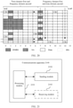
- the terminal apparatus may include at least one processor 301, a memory 302, and a transceiver 303.
- the processor 301 is a control center of the terminal apparatus, and may be one processor, or may be a collective name of a plurality of processing elements.
- the processor 301 may be a central processing unit (central processing unit, CPU), or an application specific integrated circuit (application specific integrated circuit, ASIC), or may be configured as one or more integrated circuits implementing the embodiments of this application, for example, one or more microprocessors (digital signal processor, DSP), or one or more field programmable gate arrays (field programmable gate array, FPGA).
- the processor 301 may run or execute a software program stored in the memory 302, and invoke data stored in the memory 302, to perform various functions of the terminal apparatus.
- the processor 301 may include one or more CPUs, for example, a CPU 0 and a CPU 1 that are shown in FIG. 3 .
- the terminal apparatus may include a plurality of processors, for example, the processor 301 and a processor 304 that are shown in FIG. 3 .
- Each of the processors may be a single-core processor (single-CPU) or may be a multi-core processor (multi-CPU).
- the processor herein may be one or more communications devices, circuits, and/or processing cores configured to process data (for example, a computer program instruction).
- the memory 302 may be a read-only memory (read-only memory, ROM) or another type of static storage communications device that can store static information and instructions, or a random access memory (random access memory, RAM) or another type of dynamic storage communications device that can store information and instructions, or may be an electrically erasable programmable read-only memory (electrically erasable programmable read-only memory, EEPROM), a compact disc read-only memory (compact disc read-only memory, CD-ROM) or another compact disc storage, an optical disc storage (including a compact disc, a laser disc, an optical disc, a digital versatile disc, a Blu-ray disc, or the like), a magnetic disk storage medium or another magnetic storage communications device, or any other medium that can be used to carry or store expected program code in a form of an instruction or a data structure and that can be accessed by a computer.
- the memory 302 is not limited thereto.
- the memory 302 may exist independently, or may be integrated with the processor 301.
- the memory 302 is configured to store a software program for performing the solutions of this application, and the processor 301 controls execution of the software program.
- the transceiver 303 is configured to communicate with another terminal apparatus. Certainly, the transceiver 303 may further be configured to communicate with a communications network, such as the Ethernet, a radio access network (radio access network, RAN), or a wireless local area network (wireless local area networks, WLAN).
- the transceiver 303 may include a receiving unit for implementing a receiving function and a sending unit for implementing a sending function.
- the memory 302 may store the software program or an instruction.
- the processor 301 may read the software program or the instruction from the memory 302, and execute the software program or the instruction, so that the terminal apparatus 300 can perform a communication method shown in one or more of FIG. 4 , FIG. 7 , or FIG. 14 .
- the processor 301 may perform the following S401 and S402, or perform S701 and S702, or perform S1401 and S1402.
- the processor 301 may also control the transceiver 303 to perform any one of the following S403, S703, or S1403.
- a structure of the terminal apparatus shown in FIG. 3 does not constitute a limitation on the terminal apparatus.
- the terminal apparatus may include more or fewer components than those shown in the figure, or combine some components, or have a different component arrangement.
- the terminal apparatus 300 may also be sometimes referred to as a communications apparatus or a communications device, and may be a general-purpose device or a special-purpose device.
- the terminal apparatus 300 may be a vehicle-mounted terminal, an RSU, a personal digital assistant (personal digital assistant, PDA), a mobile phone, a tablet computer, a wireless terminal device, an embedded device, the foregoing terminal device, the foregoing network device, or a device having a structure similar to the structure shown in FIG. 3 .
- a type of the terminal apparatus 300 is not limited in this embodiment of this application.
- FIG. 4 is a schematic flowchart of a communication method according to an embodiment of this application.
- the communication method may be applied to any terminal device, any network device, or the RSU in FIG. 2 .
- the communication method includes the following steps.
- S401 A first terminal apparatus determines to-be-sent first data.
- the first data includes at least one transmission block.
- the first data may be V2X service data.
- the first data may be navigation information, video information, or voice information of a vehicle-mounted terminal.
- a type of the first data is not limited in this embodiment of this application.
- the first terminal apparatus maps, starting from the 2 nd symbol in M symbols in a slot, the first data to the M symbols.
- the M symbols are M consecutive symbols in the slot.
- the M symbols may be consecutive symbols that are available for sending sidelink (sidelink, SL) data in the slot.
- a sidelink is a link used for direct communication between two or more terminals, for example, a radio link between two vehicle-mounted terminals in the internet of vehicles, or a link between two network devices.
- the first terminal apparatus maps, starting from the 2 nd symbol in the M symbols in the slot, the first data to the M symbols may include the following step:
- the first terminal apparatus maps, starting from the 2 nd symbol in the M symbols, the first data to symbols that are from the 2 nd symbol to the last symbol in the M symbols. In other words, the first data is directly mapped to all other M-1 symbols than the 1 st symbol.
- data mapped to the 1 st symbol in the M symbols may be data mapped to a first symbol.
- the first symbol may be any one of symbols that are from the 2 nd symbol to the last symbol in the M symbols.
- the 1 st symbol in the M symbols may be generated by "duplicating" a symbol to which the first data is mapped.
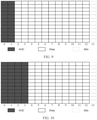
- the M symbols include symbol 0 to symbol 12 in the slot.
- the first data is mapped to symbol 1 to the symbol 12.
- the first data that is mapped to the symbol 1 is "copied" to the symbol 0.
- the "duplicating" operation cannot cover an RE that is originally used to carry a common control/reporting signal such as a reference signal, a synchronization signal, a scheduling assignment (scheduling assignment, SA) signal, or a feedback signal (such as ACK/NACK) and that is on the 1 st symbol in the M symbols.
- the "duplicating" operation is using, as mapped data on the symbol 0, the first data that is mapped to the symbol 1.
- the 1 st symbol in the M symbols is usually used for an automatic gain control (automatic gain control, AGC) procedure of a second terminal apparatus.
- AGC automatic gain control
- the second terminal apparatus collects statistics on gains, for example, receive power and signal strength, of one or more symbols that are located in the front in time domain, adjusts a gain of a subsequent symbol based on the collected receive power and signal strength, and then performs demodulation and decoding, to improve demodulation and decoding performance. Because both the data mapped to the 1 st symbol in the M symbols and another symbol in the M symbols carry the first data, a signal similarity is relatively high.
- the second terminal apparatus demodulates and decodes, based on a gain result obtained through statistics on the 1 st symbol in the M symbols, the first data carried on the another symbol in the M symbols. This can further improve a demodulation and decoding success rate, to further improve the demodulation and decoding performance of the second terminal apparatus in a scenario in which a wireless channel changes drastically.
- the 1 st symbol in the M symbols may also be generated in another way in addition to a way of performing the foregoing "duplicating" operation. For example, a random number may be placed on an RE of the 1 st symbol.
- the M symbols may be all or partial symbols in the slot. This is not limited in this embodiment of this application.
- the M symbols may start with the 1 st symbol in the slot, or may start with any symbol after the first symbol in the slot, for example, the 5 th symbol.
- the M symbols may end with the last symbol in the slot, or may end with any symbol located before the last symbol in the slot, for example, a penultimate symbol.
- one slot includes 14 symbols numbered from 0 to 13. The M symbols may start with symbol 0 and end with symbol 13, or may start with symbol 5 and end with symbol 13, or may start with symbol 0 and end with symbol 8, or may start with symbol 7 and end with symbol 13. Specific positions of the M symbols in the slot are not limited in this embodiment of this application.
- the last symbol in the M symbols may be the last symbol in the slot or the penultimate symbol in the slot.
- the 1 st symbol in the M symbols may be any one of the 1 st symbol, the 2 nd symbol, the 3 rd symbol, or the 4 th symbol in the slot.
- a symbol other than the M symbols in the slot may be allocated to another user, or may be idle. This is not limited in this application.
- the 1 st symbol in the M symbols may alternatively be determined based on a subcarrier spacing.
- a larger subcarrier spacing usually needs to be configured.
- poorer quality of the wireless channel leads to a larger subcarrier spacing that needs to be configured.
- the second terminal apparatus also needs to use more symbols to complete automatic gain control, to implement more accurate gain statistics and control, and further improve the demodulation and decoding performance.
- the 1 st symbol in the M symbols may be the 1 st symbol or the 2 nd symbol in the slot.
- the 1 st symbol in the M symbols may be the 3 rd symbol or the 4 th symbol in the slot.
- that the first terminal apparatus determines the to-be-sent first data may include the following steps.
- Step 1 The first terminal apparatus determines a scaling factor based on a first parameter.
- the first parameter includes at least one of a size of the first data, a quantity of time-frequency resources that are in the M symbols and that can be used to send the first data, or a modulation and coding scheme to be used to send the first data.
- the size of the first data is a value of a data amount of the first data.
- the time-frequency resource may include a time domain resource and a frequency domain resource.
- the time-frequency resource may be one or more configured slots, one or more configured symbols, or the like.
- the slot may be a full slot (full slot), or may be a short slot (short slot, also referred to as a mini slot, mini slot).
- the time-frequency resource may be configured frequency domain bandwidth, a configured quantity of resource blocks (resource block, RB), a configured quantity of sub-bands (sub-band), a configured quantity of band width parts (band width part, BWP, also referred to as a bandwidth part), or the like.
- the modulation and coding scheme (modulation and coding scheme, MCS, also referred to as a modulation and coding scheme) may usually include a modulation order, a bit rate, and the like.
- the scaling factor when the first terminal apparatus determines that sending resources are not reduced, the scaling factor may be 1, in other words, scaling is not performed.
- the scaling factor when the first terminal apparatus determines that the sending resources are reduced, the scaling factor is usually less than 1.
- Step 2 The first terminal apparatus determines, based on the scaling factor, a size of a transmission block included in the first data.
- the first terminal apparatus determines, based on the scaling factor, the size (transmission block size, TBS) of the transmission block carrying the first data.
- TBS transmission block size
- some symbols may be reserved for the second terminal apparatus to perform automatic gain control, and a total quantity of available resources may be less than a total quantity of resources in a normal case. Therefore, the determined scaling factor is usually less than 1. In other words, in this embodiment of this application, fewer information bits carried by the M symbols lead to a smaller transmission block of the first data sent on the M symbols.
- Step 3 The first terminal apparatus determines, based on the size of the transmission block, a quantity of transmission blocks included in the first data.
- the first data may be divided into more transmission blocks, and more time-frequency resources are required to send the first data.
- the slot may be a single slot, or may be one of a plurality of consecutive slots used to send the first data. This is not limited herein.
- the first terminal apparatus further needs to determine the scaling factor based on a second parameter.
- the second parameter includes at least one of the following parameters: a quantity of the consecutive slots used to send the first data, a number of the slot in the consecutive slots used to send the first data, or the subcarrier spacing of the slot.
- the communication method may further include the following step:
- the first terminal apparatus performs, on the M symbols, rate matching or puncturing on the first data.
- one or more symbols located foremost in the M symbols in time domain are usually used by the second terminal apparatus to perform automatic gain control.
- the 1 st symbol in the M symbols is used by the second terminal apparatus to perform automatic gain control.
- the 1 st and the 2 nd symbols in the M symbols are used by the second terminal apparatus to perform automatic gain control.
- the 1 st to the 4 th symbols in the M symbols are used by the second terminal apparatus to perform automatic gain control.
- some symbols at rear positions in the plurality of symbols may also be used to carry data, to improve resource utilization and a throughput.
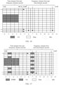
- the M symbols include 14 consecutive symbols numbered from 0 to 13.
- the first four symbols in other words, symbols 0 to 3, are used by the second terminal apparatus to perform AGC.
- One or more symbols in symbols 2 and 3 may also be used to carry data that needs to be demodulated and decoded by the second terminal apparatus.
- S403 The first terminal apparatus sends the slot carrying the first data to the second terminal apparatus.
- the first terminal apparatus may send the slot carrying the first data to the second terminal apparatus over the sidelink.
- rate matching or puncturing may be performed according to a preset rule known to both the first terminal apparatus and the second terminal apparatus, or may be independently determined by the first terminal apparatus based on a channel status fed back by the second terminal apparatus and an automatic gain control capability of the second terminal apparatus. It is easy to understand that, if the rate matching operation or the puncturing operation is performed according to a unique preset rule, the first terminal apparatus does not need to notify the second terminal apparatus.
- the first terminal apparatus independently selects a rule from a plurality of preset rules, and performs the rate matching operation or the puncturing operation according to the selected rule, or the first terminal apparatus independently determines the rate matching operation or the puncturing operation based on the channel status fed back by the second terminal apparatus and the automatic gain control capability of the second terminal apparatus, the first terminal apparatus further needs to notify the second terminal apparatus of an operation performed by the first terminal apparatus. Therefore, optionally, the first terminal apparatus sends first indication information.
- the first indication information is used to indicate that the first terminal apparatus performs rate matching or puncturing on the first data.
- the first terminal apparatus can reserve some symbols at front positions in the slot in a process of mapping the first data to the M symbols.
- the second terminal apparatus can perform automatic gain control based on the reserved symbols in the scenario in which the wireless channel changes rapidly, to reduce a bit error rate and improve receiving performance.
- FIG. 7 is a schematic flowchart of another communication method according to an embodiment of this application.
- the communication method may be applied to any terminal device, any network device, or the RSU in FIG. 2 .
- the communication method includes the following steps.
- a first terminal apparatus determines a scaling factor based on a subcarrier spacing of a first time-frequency resource to be used to send first data and/or a quantity of slots occupied by the first time-frequency resource.
- the first data is to-be-sent data of the first terminal apparatus, and the first time-frequency resource occupies a single slot or a plurality of consecutive slots.
- the scaling factor when the first terminal apparatus determines that sending resources are not reduced, the scaling factor may be 1, in other words, scaling is not performed.
- the scaling factor when the first terminal apparatus determines that the sending resources are reduced, the scaling factor is usually less than 1.
- the first time-frequency resource may occupy the single slot.
- the foregoing S701 in which the first terminal apparatus determines the scaling factor based on the subcarrier spacing of the first time-frequency resource to be used to send the first data and/or the quantity of slots occupied by the first time-frequency resource may include the following step: The first terminal apparatus determines a quantity of feature symbols in the single slot based on the subcarrier spacing. Then, the first terminal apparatus determines the scaling factor based on the quantity of feature symbols in the single slot.
- the subcarrier spacing is positively correlated with the quantity of feature symbols in the single slot.
- FIG. 8 to FIG. 10 respectively show feature symbol patterns of the single slot in different subcarrier spacing conditions.
- the subcarrier spacing is positively correlated with the quantity of feature symbols in the single slot may include: The subcarrier spacing is 15 kHz, and the quantity of feature symbols in the single slot is 2. Alternatively, the subcarrier spacing is 30 kHz or 60 kHz, and the quantity of feature symbols in the single slot is 2 or 3. Alternatively, the subcarrier spacing is 120 kHz or 240 kHz, and the quantity of feature symbols in the single slot is 3 or 5.
- the single slot usually includes one symbol used for automatic gain control performed by a second terminal apparatus and one null symbol (GAP symbol). As shown in FIG.
- the single slot usually includes two symbols used for automatic gain control performed by the second terminal apparatus and one null symbol (GAP symbol). As shown in FIG. 10 , the single slot usually includes four symbols used for automatic gain control performed by the second terminal apparatus and one null symbol (GAP symbol).
- the subcarrier spacing is 15 kHz
- the quantity of feature symbols in the single slot is 2.
- a symbol used for automatic gain control performed by the second terminal apparatus is usually located at a start position of the single slot, in other words, symbol 0.
- the other symbol is a null symbol and may be used in a scenario such as transceiving switching or radio frequency circuit switching.
- the other symbol is usually located at an end position of the single slot, in other words, the last symbol of the single slot.
- the first terminal apparatus determines the scaling factor based on the quantity of feature symbols in the single slot may include: The first terminal apparatus determines the scaling factor based on a quantity of symbols other than the feature symbol in the single slot. In other words, the first terminal apparatus determines the scaling factor based on a symbol other than all feature symbols in the single slot.
- the first terminal apparatus may also transmit valid data by using some feature symbols. For example, when two or more symbols in the single slot are used for automatic gain control performed by the second terminal apparatus, the valid data may be mapped to a symbol at a rear position in the symbols used for automatic gain control performed by the second terminal apparatus.
- the valid data is data that needs to be demodulated and decoded by the second terminal apparatus.
- the first time-frequency resource may alternatively occupy the plurality of consecutive slots.
- that the first terminal apparatus determines the scaling factor based on the subcarrier spacing of the first time-frequency resource to be used to send the first data and/or the quantity of slots occupied by the first time-frequency resource may include: The first terminal apparatus determines a quantity of feature symbols in each slot in the plurality of consecutive slots based on the subcarrier spacing and a quantity of the plurality of consecutive slots. Then, the first terminal apparatus determines, based on the quantity of feature symbols in each slot in the plurality of consecutive slots, a scaling factor corresponding to the slot in the plurality of consecutive slots.
- the subcarrier spacing is positively correlated with the quantity of feature symbols in each slot in the plurality of consecutive slots.
- FIG. 11 to FIG. 13 respectively show feature symbol patterns of a plurality of consecutive slots of different quantities in different subcarrier spacing conditions.
- a plurality of' means two or more. In a scenario of the plurality of consecutive slots, quantities of feature symbols included in different slots in the plurality of consecutive slots may be the same or different.
- that the subcarrier spacing is positively correlated with the quantity of feature symbols in each slot in the plurality of consecutive slots may include:
- the subcarrier spacing is 15 kHz, and a quantity of feature symbols in the 1 st slot in the plurality of consecutive slots is 1, for example, symbol 0 in a slot n in FIG. 11 .
- the subcarrier spacing is 30 kHz or 60 kHz, and a quantity of feature symbols in the 1 st slot in the plurality of consecutive slots is 1, for example, symbol 0 in a slot n in FIG. 11 , or is 2, for example, symbol 0 and symbol 1 in a slot n in FIG. 12 .
- the subcarrier spacing is 120 kHz or 240 kHz
- a quantity of feature symbols in the 1 st slot in the plurality of consecutive slots is 2, for example, symbol 0 and symbol 1 in a slot n in FIG. 12 , or may be 4, for example, symbol 0 to symbol 3 in a slot n in FIG. 13 .
- the last slot in the plurality of consecutive slots may relate to transceiving switching or radio frequency circuit switching. In this case, only one symbol is required. Therefore, a quantity of feature symbols in the last slot in the plurality of consecutive slots may be determined not based on the subcarrier spacing. Instead, the last symbol in the last slot is directly configured as the null symbol, for example, symbol 13 in a slot n+1 in FIG. 11 , symbol 13 in a slot n+1 in FIG. 12 , or symbol 13 in a slot n+3 in FIG. 13 .
- no feature symbol may be usually configured for a slot other than the 1 st and the last slots in the plurality of consecutive slots, in other words, an intermediate slot.
- the second terminal apparatus may complete an automatic gain control operation on the intermediate slot based on a gain statistics result of the 1 st slot. This can save resources, carry more data, and improve a data throughput.
- a different quantity or length (which may be referred to as an automatic gain control period or step) of a plurality of consecutive slots that can share the gain statistics result of the 1 st slot may be set, for example, may be 2, 4, 6, or 8 slots.
- an automatic gain control period or step a different quantity or length of a plurality of consecutive slots that can share the gain statistics result of the 1 st slot.
- a poorer wireless channel condition leads to a shorter automatic gain control period.
- a better wireless channel condition leads to a longer automatic gain control period.
- one or more symbols located foremost in each slot in the plurality of consecutive slots may be configured as a symbol (symbols) used by the second terminal apparatus to perform automatic gain control.
- symbols symbols used by the second terminal apparatus to perform automatic gain control.
- scaling factors corresponding to the different slots also need to be adjusted accordingly.
- a symbol to be used to perform automatic gain control needs to be reserved in the 1 st slot in the plurality of consecutive slots, and the last symbol in the last slot is the null symbol. Therefore, optionally, a scaling factor corresponding to the 1 st slot in the plurality of consecutive slots is different from a scaling factor corresponding to the last slot in the plurality of consecutive slots.
- the plurality of consecutive slots may further include the intermediate slot.
- the intermediate slot is any slot other than the 1 st and the last slots in the plurality of consecutive slots. Therefore, optionally, a scaling factor corresponding to the intermediate slot is different from the scaling factor corresponding to the 1 st slot; and/or a scaling factor corresponding to the intermediate slot is different from the scaling factor corresponding to the last slot.
- the scaling factor corresponding to the intermediate slot may be 1, in other words, scaling is not performed.
- the scaling factor corresponding to the 1 st slot and the scaling factor corresponding to the last slot are less than 1.
- the scaling factor corresponding to the 1 st slot is less than or equal to the factor corresponding to the last slot.
- the plurality of consecutive slots may include a plurality of intermediate slots. Therefore, further, scaling factors corresponding to the plurality of intermediate slots are the same.
- two slots corresponding to different scaling factors in the plurality of consecutive slots may carry transmission blocks of different sizes, to maximally improve resource utilization and the data throughput. It is easy to understand that two slots corresponding to a same scaling factor in the plurality of consecutive slots may carry transmission blocks of a same size, so that a same modulation and coding scheme can be used to a greatest extent. This simplifies data sending and receiving processes, and improves processing efficiency.
- a redundancy version of the first data sent in the 1 st slot is different from a redundancy version of the first data sent in the last slot; and/or a redundancy version of the first data sent in the 1 st slot is different from a redundancy version of the first data sent in any one of the intermediate slots; and/or a redundancy version of the first data sent in the last slot is different from a redundancy version of the first data sent in any one of the intermediate slots; and/or redundancy versions of the first data sent in different slots in the plurality of intermediate slots are the same.
- the sent first data has different redundancy versions, and this can maximally use a resource and avoid a waste.
- the redundancy versions of the first data sent in the plurality of intermediate slots are the same, and this can reduce complexity of a modulation and coding operation.
- the communication method shown in FIG. 7 may further include: The first terminal apparatus determines, based on a quantity of feature symbols in a first slot in the plurality of consecutive slots, the scaling factor applicable to each slot in the plurality of consecutive slots.
- the first slot is any slot in the plurality of consecutive slots.
- the first slot may be the 1 st slot in the plurality of consecutive slots. Because there are fewer available resources in the 1 st slot, the determined scaling factor is relatively small. Therefore, a data carrying capability of the 1 st slot may be less than a data carrying capability of any other slot. Therefore, correspondingly, the communication method shown in FIG. 7 may further include: The first terminal apparatus performs a rate matching operation on a transmission block in one or more slots other than the first slot in the plurality of consecutive slots. For example, a lower bit rate may be used in another slot, to improve a demodulation and decoding success rate of the second terminal apparatus.
- a quantity of available resources in the 1 st slot may be the same as a quantity of available resources in the last slot.
- a same modulation and coding scheme may be used for the 1 st slot and the last slot. For example, a same bit rate is used to perform channel coding.
- the first slot may alternatively be the last slot in the plurality of consecutive slots.
- the quantity of available resources in the last slot is usually greater than the quantity of available resources in the 1 st slot and less than a quantity of available resources in the intermediate slot.
- the communication method shown in FIG. 7 may further include one or more of the following operations: The first terminal apparatus punctures the transmission block in the 1 st slot in the plurality of consecutive slots; and/or the first terminal apparatus performs rate matching on the transmission block in any slot other than the 1 st and the last slots in the plurality of consecutive slots.
- the first slot may alternatively be any slot other than the 1 st and the last slots in the plurality of consecutive slots, namely, the intermediate slot.
- the communication method shown in FIG. 7 may further include: The first terminal apparatus punctures the transmission block in the 1 st slot and/or the last slot in the plurality of consecutive slots.
- the feature symbol may include at least one of the following symbols: the symbol to be used to perform automatic gain control, the null symbol, a symbol used to determine the scaling factor, or a symbol to which the first data is not directly mapped, for example, the 1 st symbol generated by using the duplicating method.
- the quantity of feature symbols is first determined based on the subcarrier spacing, and then the scaling factor is determined.
- the scaling factor corresponding to the single slot or each of the plurality of consecutive slots or the scaling factor corresponding to the plurality of consecutive slots may alternatively be determined directly based on the subcarrier spacing, without considering the feature symbol.
- the first terminal apparatus determines the scaling factor based on the subcarrier spacing of the first time-frequency resource to be used to send the first data and/or the quantity of slots occupied by the first time-frequency resource may include: The first terminal apparatus determines, based on the subcarrier spacing and a quantity of the plurality of consecutive slots, the scaling factor corresponding to the plurality of consecutive slots. The scaling factor corresponding to the plurality of consecutive slots is used to map a same transmission block of the first data to the plurality of consecutive slots in a scattered mode, and only some bits of the transmission block are mapped to each slot.
- that the first terminal apparatus determines the scaling factor based on the subcarrier spacing of the first time-frequency resource to be used to send the first data and/or the quantity of slots occupied by the first time-frequency resource may include the following steps:
- the first terminal apparatus determines the scaling factor based on a symbol other than the 1 st and the last symbols in the single slot.
- the first terminal apparatus determines the scaling factor based on a symbol other than the 1 st , the 2 nd , and the last symbols in the single slot.
- the first terminal apparatus determines the scaling factor based on a symbol other than the 1 st to the 4 th and the last symbols in the single slot.
- that the first terminal apparatus determines the scaling factor based on the subcarrier spacing of the first time-frequency resource to be used to send the first data and/or the quantity of slots occupied by the first time-frequency resource may include the following steps:
- the first terminal apparatus determines the scaling factor based on a symbol other than the 1 st symbol in the 1 st slot in the plurality of consecutive slots.
- the first terminal apparatus determines the scaling factor based on a symbol other than the 1 st and the 2 nd symbols in the 1 st slot in the plurality of consecutive slots.
- the first terminal apparatus determines the scaling factor based on a symbol other than the 1 st to the 4 th symbols in the 1 st slot in the plurality of consecutive slots.
- the first terminal apparatus determines the scaling factor based on a symbol other than the last symbol in the last slot in the plurality of consecutive slots.
- the first terminal apparatus determines, based on the scaling factor, a size of a transmission block carrying the first data.
- the size of the transmission block carrying the first data may be determined based on a total quantity of resources configured for the single slot or each of the plurality of consecutive slots, for example, a total quantity of configured RBs, and the scaling factor.
- N RB is a quantity that is of RBs occupied by a scaled transmission block and that is determined according to the foregoing implementations
- N RB is a total quantity of RBs configured by a network device such as a base station, or a total quantity that is of resource blocks of a transmission resource determined by UE
- P is the scaling factor determined according to the foregoing implementations, 0 ⁇ P ⁇ 1, the operator ⁇ x ⁇ represents rounding down, and the operator max ⁇ , ⁇ represents taking a maximum value.
- P 1 indicates no scaling. For example, when a channel condition is relatively good, no symbol needs to be reserved for the second terminal apparatus to perform automatic gain control, and transceiving switching and radio frequency circuit switching do not need to be performed.
- the first terminal apparatus sends the transmission block carrying the first data to the second terminal apparatus on the first time-frequency resource.
- the first terminal apparatus may send the transmission block carrying the first data to the second terminal apparatus over a sidelink.
- the communication method shown in FIG. 7 may further include: The first terminal apparatus sends first indication information.
- the first indication information is used to indicate that the first terminal apparatus determines, in the single slot or a plurality of types of slots, the size of the transmission block carrying the first data based on the scaling factor.
- the first indication information is used to indicate symbols, in the single slot or the plurality of slots, on which the second terminal apparatus performs demodulation and decoding.
- the first terminal apparatus may further need to send second indication information to the second terminal apparatus.
- the second indication information is used to indicate the second terminal apparatus to perform, in a specific slot received by the second terminal apparatus, a reverse procedure of rate matching or puncturing performed by the first terminal apparatus.
- the first terminal apparatus and the second terminal apparatus use a same preset rule to perform scaling, rate matching, or puncturing on the transmission block, in other words, the second terminal apparatus serving as a receiver can learn of details about scaling, rate matching, or puncturing performed by the first terminal apparatus on the transmission block, the first terminal apparatus may alternatively not send the first indication information or the second indication information.
- the same preset rule may be separately stored in the first terminal apparatus and the second terminal apparatus for use.
- the scaling factor and the size of the transmission block of the first data can be determined based on the subcarrier spacing of the first time-frequency resource and/or the quantity of slots occupied by the first time-frequency resource, and an adjusted transmission block of the first data is sent to the second terminal apparatus on the first time-frequency resource.
- a quantity of time-frequency resources carrying the first data also changes.
- the first terminal apparatus can dynamically adjust, based on the time-frequency resource change, a data amount of the first data carried in the single slot or the plurality of consecutive slots. This can avoid an error in demodulating and decoding the first data due to insufficient time-frequency resources, and improve data transmission reliability.
- FIG. 14 is a schematic flowchart of still another communication method according to an embodiment of this application.
- the communication method may be applied to any terminal device, any network device, or the RSU in FIG. 2 .
- the communication method includes the following steps.
- a first terminal apparatus determines a first symbol set and a second symbol set that are of first data and that are in a slot.
- the second symbol set is located, in time domain, after the first symbol set, and the first symbol set and the second symbol set are consecutive.
- the first symbol set may include the 1 st symbol in the slot, and one symbol or a plurality of consecutive symbols that is or are located after the 1 st symbol in time domain and that is or are adjacent to the 1 st symbol.
- that the first terminal apparatus determines the first symbol set and the second symbol set that are of the first data and that are in the slot may include the following step:
- the first terminal apparatus determines, based on a symbol that is occupied by control information and that is in the slot, the first symbol set.
- the control information may include scheduling assignment SA information.
- the first symbol set includes the symbol occupied by the control information.
- the first symbol set includes a symbol, in the slot, occupied by the SA information, for example, symbol 0 to symbol 3.
- the first symbol set may include one symbol or a plurality of consecutive symbols that is or are located, in time domain, after the symbol occupied by the control information and that is or are adjacent to the last symbol occupied by the control information.
- the first symbol set may further include a symbol that is not occupied by the SA information.
- the first symbol set may further include symbol 4 and symbol 5.
- the symbol 4 and the symbol 5 may be considered as reserved duration in which a second terminal apparatus demodulates and decodes the SA information carried in the symbols 0 to 3.
- a quantity of symbols in the first symbol set that do not carry the SA information may be determined based on a capability of the second terminal apparatus for demodulating and decoding the SA information, and may be represented by using a symbol quantity, for example, one symbol or three symbols, or may be represented by using absolute duration, for example, 100 microseconds (microsecond, ⁇ s) or 200 microseconds.
- the first terminal apparatus determines the first symbol set and the second symbol set that are of the first data and that are in the slot may include: The first terminal apparatus determines, based on a symbol that is occupied by a demodulation reference signal (demodulation reference signal, DMRS) and that is in the slot, the first symbol set.
- the first symbol set includes a symbol, in the slot, occupied by the 1 st DMRS.
- the 1 st DMRS occupies the symbol 0.
- the first symbol set includes the symbol 0.
- the 1 st DMRS occupies symbol 1.
- the first symbol set includes the symbol 1.
- the first symbol set may further include all symbols, in the slot, located before a symbol occupied by the 2 nd DMRS.
- the 2 nd DMRS occupies symbol 7.
- the first symbol set includes the symbol 0 to symbol 6, but does not include the symbol 7.
- the first symbol set may include the symbol, in the slot, occupied by the 2 nd DMRS.
- the 2 nd DMRS occupies symbol 7.
- the first symbol set includes the symbol 0 to the symbol 7, but does not include a symbol located after the symbol 7.
- the first symbol set includes one symbol or a plurality of consecutive symbols that is or are located, in time domain, after the symbol occupied by the 2 nd DMRS and that is or are adjacent to the symbol occupied by the 2 nd DMRS.
- the 2 nd DMRS occupies symbol 7.
- the first symbol set not only includes the symbol 0 to the symbol 7, but also includes symbol 8 and symbol 9.
- the symbol 8 and the symbol 9 may be considered as reserved duration in which the second terminal apparatus processes the 2 nd DMRS, so that the second terminal apparatus demodulates the 2 nd DMRS.
- a quantity of other symbols that are included in the first symbol set and that are located after the symbol occupied by the 2 nd DMRS may be determined based on a capability of the second terminal apparatus for demodulating the DMRS, and may be represented by using a symbol quantity, for example, one symbol or three symbols, or may be represented by using absolute duration, for example, 100 microseconds or 200 microseconds.
- that the first terminal apparatus determines the first symbol set and the second symbol set that are in the slot may include the following step:
- the first terminal apparatus determines, based on a total quantity of symbols included in the slot, the first symbol set.
- the total quantity of symbols included in the slot one-to-one corresponds to the first symbol set.
- the first terminal apparatus determines, based on the total quantity of symbols included in the slot, the first symbol set may include the following step:
- N 1 is the quantity of symbols included in the first symbol set
- L is the total quantity of symbols included in the slot
- K 1 and K 2 are preset offsets
- the operator [ ] represents rounding down
- the operator ⁇ ⁇ represents rounding up.
- the first terminal apparatus adds N 1 symbols located foremost in the slot in time domain to the first symbol set.
- the communication method shown in FIG. 14 may further include the following step:
- the first terminal apparatus determines that the total quantity of symbols included in the slot is greater than a first symbol quantity threshold.
- the first symbol quantity threshold may be a specific symbol quantity, for example, seven symbols or nine symbols, or may be a proportion of a total quantity of symbols included in one slot, for example, 1/2, 1/3, or 2/3 of the total quantity of symbols.
- the communication method shown in FIG. 14 may further include the following step:
- the first terminal apparatus determines that total duration of the slot is greater than a first duration threshold.
- the first duration threshold may be a symbol quantity, for example, seven symbols or nine symbols, or may be specific duration, for example, 0.5 milliseconds (millisecond, ms), 0.7 milliseconds, or 0.8 milliseconds.
- a specific form of the first duration threshold is not limited in this embodiment of this application.
- the first terminal apparatus determines, based on the total quantity of symbols included in the slot, the first symbol set may include the following step:
- the first terminal apparatus determines that the first symbol set includes all symbols in the slot and the second symbol set is null.
- the second symbol quantity threshold may be a specific symbol quantity, for example, three symbols or five symbols, or may be a proportion of a total quantity of symbols included in one slot, for example, 1/5, 1/7, or 1/3 of the total quantity of symbols.
- the first terminal apparatus determines, based on the total quantity of symbols included in the slot, the first symbol set may include the following step:
- the first terminal apparatus determines that the first symbol set includes all symbols in the slot and the second symbol set is null.
- the second duration threshold may be a symbol quantity, for example, three symbols or five symbols, or may be specific duration, for example, 0.5 milliseconds (millisecond, ms), 0.4 milliseconds, or 0.3 milliseconds.
- a specific form of the second duration threshold is not limited in this embodiment of this application.
- the communication method shown in FIG. 14 may further include the following step:
- the first terminal apparatus determines that the first symbol set includes a feature symbol.
- the one or two feature symbols located foremost in the slot in time domain, where the one or two feature symbols may be used by the second terminal apparatus to perform automatic gain control, and/or the feature symbol is the last symbol in the slot and may be used for transceiving switching or radio frequency circuit switching.
- that the first terminal apparatus determines that the first symbol set includes the feature symbol may include the following step:
- the first terminal apparatus determines, based on one or more of the following items, that the first symbol set includes the feature symbol: a quantity of a plurality of consecutive slots occupied by the first data, a number of a slot for one transmission block of the first data in the plurality of consecutive slots occupied by the first data, a subcarrier spacing, a size of the first data, bandwidth of a frequency domain resource for transmitting the first data, a quantity of symbols that can be used to send the first data, a modulation and coding scheme to be used to send the first data, channel state information of a current resource or resource pool, or the like.
- the communication method shown in FIG. 14 may further include the following step:
- the first terminal apparatus sends indication information.
- the indication information may be used to indicate one or more types of the following information: whether the slot includes the feature symbol, whether the first symbol set exists, whether the second symbol set exists, the quantity of symbols included in the first symbol set, a quantity of symbols included in the second symbol set, or the like.
- the feature symbol may include at least one of the following symbols: a symbol to be used to perform automatic gain control, a symbol used to determine to perform a scaling operation on a transmission block of the first data, a symbol used to determine to perform rate matching on a transmission block of the first data, or a symbol used to determine to puncture a transmission block of the first data.
- the first terminal apparatus maps the first data to the slot in the following mode to obtain second data: mapping the first data to the first symbol set in a time domain first and frequency domain second mapping mode and mapping the first data to the second symbol set in a frequency domain first and time domain second mapping mode.
- FIG. 20 shows a mapping pattern of the first data according to an embodiment of this application.
- the first symbol set includes the symbol 0 to the symbol 6, and the second symbol set includes the symbol 7 to symbol 13.
- the slot is used to map one transmission block of the first data, and the transmission block includes three code blocks (code block, CB): a CB 0, a CB 1, and a CB 2.
- the first data is mapped to the first symbol set in the symbol first and frequency domain RE second mapping mode may include: First, the 1 st batch of encoded bits of the CB 0 is respectively mapped to the 1 st REs in the symbol 0 to the symbol 6 in the symbol first and frequency domain RE second mapping mode. Then, the 2 nd batch of encoded bits of the CB 0 is respectively mapped to the 2 nd REs in the symbol 0 to the symbol 6 in the symbol first and frequency domain RE second mapping mode. The rest can be deduced by analogy. After all encoded bits in the CB 0 are mapped, the CB 1 is mapped. When encoded bits of the first data are mapped to all available REs on all symbols in the first symbol set, encoded bits of the first data start to be continuously mapped to the second symbol set.
- the first data is mapped to the second symbol set in the frequency domain RE first and symbol second mapping mode may include: First, the 1 st batch of encoded bits in the remaining encoded bits of the CB 1 is mapped to the 1 st to the last REs in the symbol 7 in sequence in the frequency domain RE first and symbol second mapping mode. Then, the 2 nd batch of encoded bits in the remaining encoded bits of the CB 1 is mapped to the 1 st to the last REs in symbol 8 in sequence in the frequency domain RE first and symbol second mapping mode. The rest can be deduced by analogy.
- the CB 2 is mapped.
- encoded bits of the first data are mapped to all available REs on all symbols in the second symbol set, or when all encoded bits in the last CB block such as the CB 2 are mapped, the mapping ends.
- an RE occupied by a common signal such as a reference signal, a synchronization signal, a scheduling assignment signal, or a feedback signal cannot be occupied.
- S1403 The first terminal apparatus sends the second data to the second terminal apparatus.
- the first terminal apparatus may send the second data to the second terminal apparatus over a sidelink.
- the first data can be mapped to the first symbol set in the slot in the time domain first and frequency domain second mapping mode, and mapped to the second symbol set in the frequency domain first and time domain second mapping mode, to generate the second data, and the second data is sent.
- the second terminal apparatus can start decoding only after receiving all the symbols in the slot, and as a result, a relatively large data transmission delay is caused;
- the symbols are not interleaved, and as a result, demodulation and decoding performance of the second terminal apparatus deteriorates greatly in a scenario in which a wireless channel changes drastically. In this way, actual requirements for a data transmission delay and demodulation and decoding performance can be considered, and this can improve reliability and efficiency of data transmission in the scenario in which the wireless channel changes drastically.
- FIG. 21 is a schematic structural diagram of a communications apparatus according to an embodiment of this application.
- the communications apparatus may be applicable to the communications system shown in FIG. 2 , and perform a function of the first terminal apparatus in the communication method shown in FIG. 4 .
- FIG. 21 shows only main components of the communications apparatus.
- the communications apparatus 2100 includes a processing module 2101 and a sending module 2102.
- the communications apparatus 2100 is used as the first terminal apparatus to communicate with a second terminal apparatus.
- the communications apparatus 2100 includes the processing module 2101 and the sending module 2102.
- the processing module 2101 is configured to determine to-be-sent first data.
- the first data includes at least one transmission block.
- the processing module 2101 is further configured to map, starting from the 2 nd symbol in M symbols in a slot, the first data to the M symbols, where the M symbols are M consecutive symbols in the slot.
- the sending module 2102 is configured to send a slot carrying the first data to the second terminal apparatus.
- the M symbols may be consecutive symbols that are available for sending sidelink data in the slot.
- the processing module 2101 is further configured to map, starting from the 2 nd symbol in the M symbols, the first data to symbols that are from the 2 nd symbol to the last symbol in the M symbols.
- data mapped to the 1 st symbol in the M symbols is data mapped to a first symbol.
- the first symbol may be any one of symbols that are from the 2 nd symbol to the last symbol in the M symbols.
- the last symbol in the M symbols may be the last symbol in the slot or a penultimate symbol in the slot.
- the 1 st symbol in the M symbols may be any one of the 1 st symbol, the 2 nd symbol, the 3 rd symbol, or the 4 th symbol in the slot.
- the 1 st symbol in the M symbols may be the 1 st symbol or the 2 nd symbol in the slot.
- the 1 st symbol in the M symbols may be the 3 rd symbol or the 4 th symbol in the slot.
- the processing module 2101 is further configured to determine a scaling factor based on a first parameter.
- the first parameter includes at least one of a size of the first data, a quantity of time-frequency resources that are in the M symbols and that can be used to send the first data, or a modulation and coding scheme to be used to send the first data.
- the processing module 2101 is further configured to determine a size of a transmission block based on the scaling factor.
- the processing module 2101 is further configured to determine, based on the size of the transmission block, a quantity of transmission blocks included in the first data.
- the slot is one of a plurality of consecutive slots used to send the first data.
- the processing module 2101 is further configured to determine the scaling factor based on a second parameter.
- the second parameter includes at least one of the following parameters: a quantity of the consecutive slots used to send the first data, a number of the slot in the consecutive slots used to send the first data, or the subcarrier spacing of the slot.
- the sending module 2102 is further configured to send first indication information to the second terminal apparatus.
- the first indication information is used to indicate that the first terminal apparatus performs rate matching or puncturing on the first data.
- the 1 st symbol in the M symbols may be used by the second terminal apparatus to perform automatic gain control.
- the 1 st and the 2 nd symbols in the M symbols may be used by the second terminal apparatus to perform automatic gain control.
- the 1 st to the 4 th symbols in the M symbols may be used by the second terminal apparatus to perform automatic gain control.
- the communications apparatus 2100 shown in FIG. 21 may further include a receiving module 2103, so that the communications apparatus 2100 can also perform a function performed by the second terminal device in the communication method shown in FIG. 4 , to implement bidirectional communication.
- the communications apparatus 2100 may be the terminal device, the RSU, or the network device shown in FIG. 2 , or may be a chip or a chip system disposed in the terminal device, the RSU, or the network device. This is not limited in this embodiment of this application.
- FIG. 22 is a schematic structural diagram of a communications apparatus according to an embodiment of this application.
- the communications apparatus may be applicable to the communications system shown in FIG. 2 , and perform a function of the first terminal apparatus in the communication method shown in FIG. 7 .
- FIG. 22 shows only main components of the communications apparatus.
- the communications apparatus 2200 includes a processing module 2201 and a sending module 2202.
- the processing module 2201 is configured to determine a scaling factor based on a subcarrier spacing of a first time-frequency resource to be used to send first data and/or a quantity of slots occupied by the first time-frequency resource.
- the first data is to-be-sent data of the first terminal apparatus, and the first time-frequency resource occupies a single slot or a plurality of consecutive slots.
- the processing module 2201 is further configured to determine, based on the scaling factor, a size of a transmission block carrying the first data.
- the sending module 2202 is configured to send the transmission block carrying the first data to a second terminal apparatus on the first time-frequency resource.
- the sending module 2202 is further configured to send first indication information.
- the first indication information is used to indicate that the first terminal apparatus determines, in the single slot or the plurality of consecutive slots, the size of the transmission block carrying the first data based on the scaling factor.
- the first time-frequency resource may occupy the single slot.
- the processing module 2201 is further configured to determine a quantity of feature symbols in the single slot based on the subcarrier spacing.
- the subcarrier spacing is positively correlated with the quantity of feature symbols in the single slot.
- the processing module 2201 is further configured to determine the scaling factor based on the quantity of feature symbols in the single slot.
- the subcarrier spacing is positively correlated with the quantity of feature symbols in the single slot may include: The subcarrier spacing is 15 kHz, and the quantity of feature symbols in the single slot is 2. Alternatively, the subcarrier spacing is 30 kHz or 60 kHz, and the quantity of feature symbols in the single slot is 2 or 3. Alternatively, the subcarrier spacing is 120 kHz or 240 kHz, and the quantity of feature symbols in the single slot is 3 or 5.
- processing module 2201 is further configured to determine the scaling factor based on a quantity of symbols other than the feature symbol in the single slot.
- the first time-frequency resource may occupy the plurality of consecutive slots.
- the processing module 2201 is further configured to determine a quantity of feature symbols in each slot in the plurality of consecutive slots based on the subcarrier spacing and a quantity of the plurality of consecutive slots.
- the subcarrier spacing is positively correlated with the quantity of feature symbols in each slot in the plurality of consecutive slots.
- the processing module 2201 is further configured to determine, based on the quantity of feature symbols in each slot in the plurality of consecutive slots, a scaling factor corresponding to the slot in the plurality of consecutive slots.
- the subcarrier spacing is positively correlated with the quantity of feature symbols in each slot in the plurality of consecutive slots may include:
- the subcarrier spacing is 15 kHz, and a quantity of feature symbols in the 1 st slot in the plurality of consecutive slots is 1.
- the subcarrier spacing is 30 kHz or 60 kHz, and a quantity of feature symbols in the 1 st slot in the plurality of consecutive slots is 1 or 2.
- the subcarrier spacing is 120 kHz or 240 kHz, and a quantity of feature symbols in the 1 st slot in the plurality of consecutive slots is 2 or 4.
- a scaling factor corresponding to the 1 st slot in the plurality of consecutive slots is different from a scaling factor corresponding to the last slot in the plurality of consecutive slots.
- the plurality of consecutive slots may further include an intermediate slot.
- the intermediate slot may be any slot other than the 1 st and the last slots in the plurality of consecutive slots.
- a scaling factor corresponding to the intermediate slot is different from the scaling factor corresponding to the 1 st slot; and/or a scaling factor corresponding to the intermediate slot is different from the scaling factor corresponding to the last slot.
- the plurality of consecutive slots may include a plurality of intermediate slots.
- scaling factors corresponding to the plurality of intermediate slots are the same.
- a redundancy version of the first data sent in the 1 st slot is different from a redundancy version of the first data sent in the last slot; and/or a redundancy version of the first data sent in the 1 st slot is different from a redundancy version of the first data sent in any one of the intermediate slots; and/or a redundancy version of the first data sent in the last slot is different from a redundancy version of the first data sent in any one of the intermediate slots; and/or redundancy versions of the first data sent in different slots in the intermediate slots are the same.
- the processing module 2201 is further configured to: after the first terminal apparatus determines the quantity of feature symbols in each slot in the plurality of consecutive slots based on the subcarrier spacing and the quantity of the plurality of consecutive slots, determine, based on a quantity of feature symbols in a first slot in the plurality of consecutive slots, a scaling factor applicable to each slot in the plurality of consecutive slots.
- the first slot may be any slot in the plurality of consecutive slots.
- the first slot may be the 1 st slot in the plurality of consecutive slots.
- the processing module 2201 is further configured to perform rate matching on the transmission block in one or more slots other than the first slot in the plurality of consecutive slots.
- the first slot may be the last slot in the plurality of consecutive slots.
- the processing module 2201 is further configured to puncture the transmission block in the 1 st slot in the plurality of consecutive slots; and/or the processing module 2201 is further configured to perform rate matching on the transmission block in any slot other than the 1 st and the last slots in the plurality of consecutive slots.
- the first slot may be any slot other than the 1 st and the last slots in the plurality of consecutive slots.
- the processing module 2201 is further configured to puncture the transmission block in the 1 st slot and/or the last slot in the plurality of consecutive slots.
- the feature symbol may include at least one of the following symbols: a symbol to be used to perform automatic gain control, a null symbol, a symbol used to determine the scaling factor, or a symbol to which the first data is not directly mapped.
- all of the plurality of consecutive slots are only used to send one transmission block of the first data.
- the processing module 2201 is further configured to determine, based on the subcarrier spacing and a quantity of the plurality of consecutive slots, one scaling factor corresponding to the plurality of consecutive slots.
- the first time-frequency resource may occupy the single slot.
- the processing module 2201 is further configured to: when the subcarrier spacing is 15 kHz or 30 kHz, determine the scaling factor based on a symbol other than the 1 st and the last symbols in the single slot.
- the processing module 2201 is further configured to: when the subcarrier spacing is 30 kHz, 60 kHz, or 120 kHz, determine the scaling factor based on a symbol other than the 1 st , the 2 nd , and the last symbols in the single slot.
- the processing module 2201 is further configured to: when the subcarrier spacing is 120 kHz or 240 kHz, determine the scaling factor based on a symbol other than the 1 st to the 4 th and the last symbols in the single slot.
- the first time-frequency resource may occupy the plurality of consecutive slots.
- the processing module 2201 is further configured to: when the subcarrier spacing is 15 kHz or 30 kHz, determine the scaling factor based on a symbol other than the 1 st symbol in the 1 st slot in the plurality of consecutive slots.
- the processing module 2201 is further configured to: when the subcarrier spacing is 30 kHz, 60 kHz, or 120 kHz, determine the scaling factor based on a symbol other than the 1 st and the 2 nd symbols in the 1 st slot in the plurality of consecutive slots.
- the processing module 2201 is further configured to: when the subcarrier spacing is 120 kHz or 240 kHz, determine the scaling factor based on a symbol other than the 1 st to the 4 th symbols in the 1 st slot in the plurality of consecutive slots. Alternatively, the processing module 2201 is further configured to determine the scaling factor based on a symbol other than the last symbol in the last slot in the plurality of consecutive slots.
- the communications apparatus 2200 shown in FIG. 22 may further include a receiving module 2203, so that the communications apparatus 2200 can also perform a function performed by the second terminal device in the communication method shown in FIG. 7 , to implement bidirectional communication.
- the communications apparatus 2200 may be the terminal device, the RSU, or the network device shown in FIG. 2 , or may be a chip or a chip system disposed in the terminal device, the RSU, or the network device. This is not limited in this embodiment of this application.
- FIG. 23 is a schematic structural diagram of another communications apparatus according to an embodiment of this application.
- the communications apparatus may be applicable to the communications system shown in FIG. 2 , and perform a function of the first terminal apparatus in the communication method shown in FIG. 14 .
- FIG. 23 shows only main components of the communications apparatus.
- the communications apparatus 2300 includes a processing module 2301 and a sending module 2302.
- the processing module 2301 is configured to determine a first symbol set and a second symbol set that are of first data and that are in a slot.
- the second symbol set is located, in time domain, after the first symbol set, and the first symbol set and the second symbol set are consecutive.
- the processing module 2301 is further configured to map, by the first terminal apparatus, the first data to the slot in the following mode to obtain second data: mapping the first data to the first symbol set in a time domain first and frequency domain second mapping mode and mapping the first data to the second symbol set in a frequency domain first and time domain second mapping mode.
- the sending module 2302 is configured to send a transmission block carrying the first data.
- the first symbol set may include the 1 st symbol in the slot, and one symbol or a plurality of consecutive symbols that are located after the 1 st symbol in time domain and that are adjacent to the 1 st symbol.
- the processing module 2301 is further configured to determine, based on a symbol that is occupied by control information and that is in the slot, the first symbol set.
- the first symbol set may include the symbol occupied by the control information.
- the first symbol set may include one symbol or a plurality of consecutive symbols that is or are located, in time domain, after the symbol occupied by the control information and that is or are adjacent to the last symbol occupied by the control information.
- the processing module 2301 is further configured to determine, based on a symbol that is occupied by a demodulation reference signal DMRS and that is in the slot, the first symbol set.
- the first symbol set may include a symbol, in the slot, occupied by the 1 st DMRS.
- the first symbol set may include all symbols, in the slot, located before a symbol occupied by the 2 nd DMRS.
- the first symbol set may include the symbol, in the slot, occupied by the 2 nd DMRS.
- the first symbol set may include one symbol or a plurality of consecutive symbols that is or are located, in time domain, after the symbol occupied by the 2 nd DMRS and that is or are adjacent to the symbol occupied by the 2 nd DMRS.
- the processing module 2301 is further configured to determine, based on a total quantity of symbols included in the slot, the first symbol set.
- the total quantity of symbols included in the slot one-to-one corresponds to the first symbol set.
- N 1 is the quantity of symbols included in the first symbol set
- L is the total quantity of symbols included in the slot
- K 1 and K 2 are preset offsets
- the operator [ ] represents rounding down
- the operator ⁇ ⁇ represents rounding up.
- the first terminal apparatus adds N 1 symbols located foremost in the slot in time domain to the first symbol set.
- the processing module 230 1 is further configured to: before the first terminal apparatus determines, according to any one of the following formulas, the quantity of symbols included in the first symbol set, determine that the total quantity of symbols included in the slot is greater than a first symbol quantity threshold.
- the processing module 2301 is further configured to: if the total quantity of symbols included in the slot is less than a second symbol quantity threshold, determine that the first symbol set includes all symbols in the slot and the second symbol set is null.
- the processing module 2301 is further configured to: before the first terminal apparatus determines the first symbol set and the second symbol set that are in the slot, determine that the first symbol set includes a feature symbol. There may be one or two feature symbols located foremost in the slot in time domain.
- the processing module 2301 is further configured to determine, based on one or more of the following items, that the first symbol set includes the feature symbol: a quantity of slots consecutively occupied for transmitting the first data, numbers of a plurality of slots consecutively occupied by the first data, a subcarrier spacing to be used to transmit the first data, a size of the first data, bandwidth of a frequency domain resource for transmitting the first data, a quantity of symbols that can be used to send the first data, a modulation and coding scheme to be used to send the first data, or channel state information of a current resource or resource pool.
- the sending module 2302 is further configured to send indication information to the first terminal apparatus.
- the indication information may be used to indicate one or more types of the following information: whether the slot includes the feature symbol, the quantity of symbols included in the first symbol set, whether the first symbol set exists, or whether the second symbol set exists.
- the feature symbol may include at least one of the following symbols: a symbol to be used to perform automatic gain control, a symbol used to determine to perform a scaling operation on the transmission block of the first data, a symbol used to determine to perform a rate matching operation on the transmission block of the first data, or a symbol used to determine to perform a puncturing operation on the transmission block of the first data.
- the communications apparatus 2300 shown in FIG. 23 may further include a receiving module 2303, so that the communications apparatus 2300 can also perform a function performed by the second terminal device in the communication method shown in FIG. 14 , to implement bidirectional communication.
- the communications apparatus 2300 may be the terminal device, the RSU, or the network device shown in FIG. 2 , or may be a chip or a chip system disposed in the terminal device, the RSU, or the network device. This is not limited in this embodiment of this application.
- the second terminal apparatus may perform a function corresponding to the function of the first terminal apparatus.
- the communication method shown in FIG. 7 is used as an example.
- the second terminal apparatus may perform the following step: The second terminal apparatus receives, from the first terminal apparatus, the transmission block carrying the first data. Then, the second terminal apparatus determines a scaling factor based on a subcarrier spacing of a first time-frequency resource of the first data and/or a quantity of slots occupied by the first time-frequency resource. The first time-frequency resource occupies a single slot or a plurality of consecutive slots. The second terminal apparatus determines, based on the scaling factor, a size of the transmission block carrying the first data, and performs a decoding operation based on the size of the transmission block.
- the second terminal apparatus may further perform another function that can be performed by the second terminal apparatus in the communication method shown in FIG. 7 .
- the second terminal apparatus may further perform another function that can be performed by the second terminal apparatus in the communication method shown in FIG. 7 .
- the first terminal apparatus in the communication method shown in FIG. 7 Details are not described herein again.
- the first terminal apparatus may also perform a receiving function, and correspondingly, the second terminal apparatus may also perform a sending function.
- the communications apparatus 2300 may be the terminal device, the RSU, or the network device shown in FIG. 2 , or may be a chip or a chip system disposed in the terminal device, the RSU, or the network device. This is not limited in this embodiment of this application.
- FIG. 24 is a schematic structural diagram of still another communications apparatus according to an embodiment of this application.
- the communications apparatus may be applicable to the communications system shown in FIG. 2 , and perform a function of the second terminal apparatus in the communication method shown in FIG. 7 .
- FIG. 24 shows only main components of the communications apparatus.
- the communications apparatus 2400 includes a processing module 2401 and a receiving module 2402.
- the receiving module 2402 is further configured to receive, from a first terminal apparatus, a transmission block carrying first data.
- the processing module 2401 is further configured to determine a scaling factor based on a subcarrier spacing of a first time-frequency resource of the first data and/or a quantity of slots occupied by the first time-frequency resource.
- the first time-frequency resource occupies a single slot or a plurality of consecutive slots.
- the processing module 2401 is further configured to determine, based on the scaling factor, a size of the transmission block carrying the first data, and perform a decoding operation based on the size of the transmission block.
- the communications apparatus 2400 may further perform another function that can be performed by the second terminal apparatus in the communication method shown in FIG. 7 .
- the communications apparatus 2400 may further perform another function that can be performed by the second terminal apparatus in the communication method shown in FIG. 7 .
- the communications apparatus 2400 may further perform another function that can be performed by the second terminal apparatus in the communication method shown in FIG. 7 .
- the communications apparatus 2400 may further perform another function that can be performed by the second terminal apparatus in the communication method shown in FIG. 7 .
- the communications apparatus 2400 may further perform another function that can be performed by the second terminal apparatus in the communication method shown in FIG. 7 .
- FIG. 7 For details, refer to related descriptions of the second terminal apparatus in the communication method shown in FIG. 7 . Details are not described herein again.
- the communications apparatus 2400 may also perform a sending function.
- the communications apparatus 2400 may further include a sending module 2403.
- the sending module 2403 is configured to send signaling or data to the first terminal apparatus.
- the communications apparatus 2400 may be the terminal device, the RSU, or the network device shown in FIG. 2 , or may be a chip or a chip system disposed in the terminal device, the RSU, or the network device. This is not limited in this embodiment of this application.
- An embodiment of this application provides a communications system.
- the communications system includes the foregoing first terminal apparatus and the foregoing second terminal apparatus.
- An embodiment of this application provides a computer-readable storage medium.
- the computer-readable storage medium stores a computer instruction.
- the computer instruction When the computer instruction is run on a computer, the computer is enabled to perform the communication method shown in any one of FIG. 4 , FIG. 7 , or FIG. 14 .
- An embodiment of this application provides a computer program product including an instruction.
- the computer program product includes a computer program or instruction.
- the computer program or instruction When the computer program or instruction is run on a computer, the computer is enabled to perform the communication method shown in any one of FIG. 4 , FIG. 7 , or FIG. 14 .
- the processor in the embodiments of this application may be a central processing unit (central processing unit, CPU), or may be another general-purpose processor, a digital signal processor (digital signal processor, DSP), an application-specific integrated circuit (application specific integrated circuit, ASIC), a field programmable gate array (field programmable gate array, FPGA) or another programmable logic device, a discrete gate or transistor logic device, a discrete hardware component, or the like.
- the general-purpose processor may be a microprocessor, or the processor may be any conventional processor or the like.
- the memory in the embodiments of this application may be a volatile memory or a nonvolatile memory, or may include a volatile memory and a nonvolatile memory.
- the nonvolatile memory may be a read-only memory (read-only memory, ROM), a programmable read-only memory (programmable ROM, PROM), an erasable programmable read-only memory (erasable PROM, EPROM), an electrically erasable programmable read-only memory (electrically EPROM, EEPROM), or a flash memory.
- the volatile memory may be a random access memory (random access memory, RAM), used as an external cache.
- random access memories in many forms may be used, for example, a static random access memory (static RAM, SRAM), a dynamic random access memory (DRAM), a synchronous dynamic random access memory (synchronous DRAM, SDRAM), a double data rate synchronous dynamic random access memory (double data rate SDRAM, DDR SDRAM), an enhanced synchronous dynamic random access memory (enhanced SDRAM, ESDRAM), a synchlink dynamic random access memory (synchlink DRAM, SLDRAM), and a direct rambus random access memory (direct rambus RAM, DR RAM).
- static random access memory static random access memory
- DRAM dynamic random access memory
- SDRAM synchronous dynamic random access memory
- double data rate SDRAM double data rate SDRAM
- DDR SDRAM double data rate SDRAM
- ESDRAM enhanced synchronous dynamic random access memory
- synchlink dynamic random access memory synchlink dynamic random access memory
- direct rambus RAM direct rambus RAM, DR RAM
- All or some of the foregoing embodiments may be implemented by using software, hardware (for example, circuit), firmware, or any combination thereof.
- the foregoing embodiments may be implemented completely or partially in a form of a computer program product.
- the computer program product includes one or more computer instructions or computer programs. When the program instructions or the computer programs are loaded and executed on a computer, the procedures or functions according to the embodiments of this application are all or partially generated.
- the computer may be a general-purpose computer, a special-purpose computer, a computer network, or another programmable apparatus.
- the computer instructions may be stored in a computer-readable storage medium or may be transmitted from a computer-readable storage medium to another computer-readable storage medium.
- the computer instructions may be transmitted from a website, computer, server, or data center to another website, computer, server, or data center in a wired (for example, infrared, radio, or microwave) form.
- the computer-readable storage medium may be any usable medium accessible by a computer, or a data storage device, such as a server or a data center, integrating one or more usable media.
- the usable medium may be a magnetic medium (for example, a floppy disk, a hard disk, or a magnetic tape), an optical medium (for example, a DVD), or a semiconductor medium.
- the semiconductor medium may be a solid state drive.
- At least one means one or more, and "a plurality of” means two or more than two.
- At least one of the following items (pieces) or a similar expression thereof indicates any combination of these items, including a single item (piece) or any combination of a plurality of items (pieces).
- at least one of a, b, or c may indicate: a, b, c, a and b, a and c, b and c, or a, b, and c, where a, b, and c may be singular or plural.
- sequence numbers of the foregoing processes do not mean execution sequences in various embodiments of this application.
- the execution sequences of the processes should be determined based on functions and internal logic of the processes, and should not be construed as any limitation on the implementation processes of the embodiments of this application.
- the disclosed system, apparatus, and method may be implemented in other ways.
- the described apparatus embodiment is merely an example.
- division into the units is merely logical function division and may be other division in actual implementation.
- a plurality of units or components may be combined or integrated into another system, or some features may be ignored or not performed.
- the displayed or discussed mutual couplings or direct couplings or communication connections may be implemented through some interfaces.
- the indirect couplings or communication connections between the apparatuses or units may be implemented in electrical, mechanical, or other forms.
- the units described as separate parts may or may not be physically separate, and parts displayed as units may or may not be physical units, may be located in one position, or may be distributed on a plurality of network units. Some or all of the units may be selected based on actual requirements to achieve the objectives of the solutions of the embodiments.
- the functions When the functions are implemented in a form of a software functional unit and sold or used as an independent product, the functions may be stored in a computer-readable storage medium. Based on such an understanding, the technical solutions of this application essentially, or the part contributing to the prior art, or some of the technical solutions may be implemented in a form of a software product.
- the computer software product is stored in a storage medium, and includes several instructions for instructing a computer device (which may be a personal computer, a server, a network device, or the like) to perform all or some of the steps of the methods described in the embodiments of this application.
- the foregoing storage medium includes: any medium that can store program code, such as a USB flash drive, a removable hard disk, a read-only memory (read-only memory, ROM), a random access memory (random access memory, RAM), a magnetic disk, or an optical disc.
- program code such as a USB flash drive, a removable hard disk, a read-only memory (read-only memory, ROM), a random access memory (random access memory, RAM), a magnetic disk, or an optical disc.
Landscapes
- Engineering & Computer Science (AREA)
- Signal Processing (AREA)
- Computer Networks & Wireless Communication (AREA)
- Quality & Reliability (AREA)
- Mobile Radio Communication Systems (AREA)
- Detection And Prevention Of Errors In Transmission (AREA)
Priority Applications (1)
| Application Number | Priority Date | Filing Date | Title |
|---|---|---|---|
| EP25192145.8A EP4661323A3 (fr) | 2019-03-29 | 2020-03-25 | Procédé de communication et appareil de communication |
Applications Claiming Priority (2)
| Application Number | Priority Date | Filing Date | Title |
|---|---|---|---|
| CN201910252651.2A CN111756476B (zh) | 2019-03-29 | 2019-03-29 | 通信方法及装置 |
| PCT/CN2020/081190 WO2020200014A1 (fr) | 2019-03-29 | 2020-03-25 | Procédé et dispositif de communication |
Related Child Applications (1)
| Application Number | Title | Priority Date | Filing Date |
|---|---|---|---|
| EP25192145.8A Division EP4661323A3 (fr) | 2019-03-29 | 2020-03-25 | Procédé de communication et appareil de communication |
Publications (2)
| Publication Number | Publication Date |
|---|---|
| EP3952156A1 true EP3952156A1 (fr) | 2022-02-09 |
| EP3952156A4 EP3952156A4 (fr) | 2022-06-01 |
Family
ID=72664969
Family Applications (2)
| Application Number | Title | Priority Date | Filing Date |
|---|---|---|---|
| EP20783398.9A Withdrawn EP3952156A4 (fr) | 2019-03-29 | 2020-03-25 | Procédé et dispositif de communication |
| EP25192145.8A Pending EP4661323A3 (fr) | 2019-03-29 | 2020-03-25 | Procédé de communication et appareil de communication |
Family Applications After (1)
| Application Number | Title | Priority Date | Filing Date |
|---|---|---|---|
| EP25192145.8A Pending EP4661323A3 (fr) | 2019-03-29 | 2020-03-25 | Procédé de communication et appareil de communication |
Country Status (8)
| Country | Link |
|---|---|
| US (1) | US12058671B2 (fr) |
| EP (2) | EP3952156A4 (fr) |
| JP (1) | JP7499785B2 (fr) |
| KR (1) | KR20210139458A (fr) |
| CN (3) | CN111756476B (fr) |
| BR (1) | BR112021019275A2 (fr) |
| MX (1) | MX2021011872A (fr) |
| WO (1) | WO2020200014A1 (fr) |
Families Citing this family (8)
| Publication number | Priority date | Publication date | Assignee | Title |
|---|---|---|---|---|
| EP4150833A1 (fr) * | 2020-05-14 | 2023-03-22 | Telefonaktiebolaget LM ERICSSON (PUBL) | Mécanisme de déclenchement et de rapport pour un changement de scs |
| WO2022141593A1 (fr) | 2020-12-31 | 2022-07-07 | 华为技术有限公司 | Procédé et appareil de communication |
| EP4282109A1 (fr) * | 2021-01-20 | 2023-11-29 | Telefonaktiebolaget LM Ericsson (publ) | Taille de bloc de données |
| CN113632582B (zh) * | 2021-07-08 | 2024-02-27 | 北京小米移动软件有限公司 | 基于物理直连通信数据信道的通信方法、装置及存储介质 |
| JP7816503B2 (ja) * | 2021-09-28 | 2026-02-18 | 日本電気株式会社 | 通信の方法、装置及びコンピュータ可読媒体 |
| US11800463B2 (en) * | 2021-12-22 | 2023-10-24 | Qualcomm Incorporated | Enhanced automatic gain control for sidelink communication |
| US12470316B2 (en) * | 2022-09-23 | 2025-11-11 | Qualcomm Incorporated | Fast automatic gain control in bypass and filter modes |
| JP7755087B2 (ja) | 2022-09-28 | 2025-10-15 | 上▲海▼移▲遠▼通信技▲術▼股▲分▼有限公司 | サイドリンク通信のための方法およびデバイス |
Family Cites Families (24)
| Publication number | Priority date | Publication date | Assignee | Title |
|---|---|---|---|---|
| US9030977B2 (en) * | 2009-10-15 | 2015-05-12 | Qualcomm Incorporated | Methods and apparatus for transport block size determination |
| EP2810507B1 (fr) * | 2012-01-30 | 2020-01-15 | Telefonaktiebolaget LM Ericsson (publ) | Procédés et noeuds de réseau pour planifier une transmission |
| US8971271B2 (en) * | 2012-01-30 | 2015-03-03 | Telefonaktiebolaget L M Ericsson (Publ) | Methods and network nodes for scheduling transmission |
| US9532337B2 (en) * | 2012-05-19 | 2016-12-27 | Google Technology Holdings LLC | Method and apparatus for transport block signaling in a wireless communication system |
| WO2015018000A1 (fr) * | 2013-08-07 | 2015-02-12 | 华为技术有限公司 | Procédé et dispositif de traitement d'informations en liaison montante |
| WO2015065015A1 (fr) | 2013-10-28 | 2015-05-07 | 엘지전자 주식회사 | Procédé et appareil d'émission et de réception de signal pour un terminal dispositif à dispositif dans un système de communication sans fil |
| WO2015178816A1 (fr) * | 2014-05-23 | 2015-11-26 | Telefonaktiebolaget L M Ericsson (Publ) | Dispositifs radio et procédés d'établissement d'une communication par l'intermédiaire d'un spectre avec licence et sans licence |
| US11197317B2 (en) * | 2014-12-23 | 2021-12-07 | Qualcomm Incorporated | Techniques for determining a symbol period for a starting symbol of a transmission in a shared radio frequency spectrum |
| CN106209330B (zh) | 2015-05-08 | 2019-06-28 | 电信科学技术研究院 | 一种下行数据重复传输方法及设备 |
| US10644848B2 (en) | 2015-08-13 | 2020-05-05 | Electronics And Telecommunications Research Institute | Operation method of communication node supporting direct communication in network |
| ES2991013T3 (es) * | 2015-08-14 | 2024-12-02 | Sun Patent Trust | Adaptación del orden de modulación para subtramas parciales |
| JP6641465B2 (ja) | 2015-10-01 | 2020-02-05 | エルジー エレクトロニクス インコーポレイティド | D2d通信における参照信号送信方法及び端末 |
| CN106992847B (zh) | 2016-01-20 | 2021-01-26 | 中兴通讯股份有限公司 | 上行数据发送、接收方法、装置、终端及基站 |
| WO2017135745A1 (fr) * | 2016-02-04 | 2017-08-10 | 엘지전자 주식회사 | Procédé pour mapper, transmettre ou recevoir des informations de commande de liaison montante dans un système de communication sans fil, et dispositif associé |
| US10039102B2 (en) * | 2016-08-24 | 2018-07-31 | Lg Electronics Inc. | Method for performing a transmission on a sidelink subframe and wireless device thereof |
| CN107888528B (zh) * | 2016-09-29 | 2020-06-02 | 电信科学技术研究院 | 一种数据发送方法、接收方法及装置 |
| KR102341337B1 (ko) * | 2017-01-13 | 2021-12-20 | 엘지전자 주식회사 | 사이드링크를 통해 harqack/nack 신호를 전송하는 방법 및 단말 |
| CN109565361B (zh) | 2017-03-23 | 2021-10-01 | Lg电子株式会社 | 用于确定传输块大小的方法及无线装置 |
| EP3544358B1 (fr) * | 2017-03-31 | 2021-06-02 | LG Electronics Inc. | Procédé d'émission de signal par un terminal pour une communication v2x dans un système de communication sans fil et appareil d'utilisation associé |
| CN108809591B (zh) * | 2017-05-05 | 2021-03-30 | 华为技术有限公司 | 数据处理方法和装置 |
| EP3747219A4 (fr) * | 2018-02-02 | 2021-09-22 | Telefonaktiebolaget LM Ericsson (publ) | Noeud sans fil pour recevoir un signal sans fil et son procédé |
| CN110166198B (zh) * | 2018-02-12 | 2024-07-02 | 北京三星通信技术研究有限公司 | 旁路信号发送方法和设备 |
| CN115835388A (zh) * | 2018-09-26 | 2023-03-21 | 瑞典爱立信有限公司 | 用于副链路无线电通信的技术 |
| US12089183B2 (en) * | 2019-11-19 | 2024-09-10 | Qualcomm Incorporated | Initializing sequence generators to facilitate sidelink communications |
-
2019
- 2019-03-29 CN CN201910252651.2A patent/CN111756476B/zh active Active
- 2019-03-29 CN CN202410687562.1A patent/CN118540022A/zh active Pending
- 2019-03-29 CN CN202011429247.7A patent/CN112713962B/zh active Active
-
2020
- 2020-03-25 JP JP2021557714A patent/JP7499785B2/ja active Active
- 2020-03-25 BR BR112021019275A patent/BR112021019275A2/pt unknown
- 2020-03-25 WO PCT/CN2020/081190 patent/WO2020200014A1/fr not_active Ceased
- 2020-03-25 EP EP20783398.9A patent/EP3952156A4/fr not_active Withdrawn
- 2020-03-25 EP EP25192145.8A patent/EP4661323A3/fr active Pending
- 2020-03-25 KR KR1020217035119A patent/KR20210139458A/ko not_active Ceased
- 2020-03-25 MX MX2021011872A patent/MX2021011872A/es unknown
-
2021
- 2021-09-28 US US17/487,921 patent/US12058671B2/en active Active
Also Published As
| Publication number | Publication date |
|---|---|
| EP4661323A3 (fr) | 2026-03-25 |
| CN111756476B (zh) | 2024-06-14 |
| US12058671B2 (en) | 2024-08-06 |
| JP7499785B2 (ja) | 2024-06-14 |
| BR112021019275A2 (pt) | 2022-01-04 |
| CN112713962B (zh) | 2022-05-24 |
| KR20210139458A (ko) | 2021-11-22 |
| EP3952156A4 (fr) | 2022-06-01 |
| CN112713962A (zh) | 2021-04-27 |
| WO2020200014A1 (fr) | 2020-10-08 |
| CN118540022A (zh) | 2024-08-23 |
| EP4661323A2 (fr) | 2025-12-10 |
| US20220022216A1 (en) | 2022-01-20 |
| MX2021011872A (es) | 2021-11-17 |
| JP2022529103A (ja) | 2022-06-17 |
| CN111756476A (zh) | 2020-10-09 |
Similar Documents
| Publication | Publication Date | Title |
|---|---|---|
| US20250125917A1 (en) | Method for Data Transmission and Terminal Device | |
| US12058671B2 (en) | Communication method and communications apparatus | |
| CN113783663B (zh) | 传输信息的方法、终端设备和网络设备 | |
| CN108809545B (zh) | 传输上行控制信息的方法和装置 | |
| US12610383B2 (en) | Physical sidelink feedback channel (PSFCH) transmission method and terminal device | |
| EP3952186A1 (fr) | Procédé et appareil de transmission d'informations de commande de liaison montante | |
| EP3627932A1 (fr) | Procédé de communication, dispositif terminal et dispositif de réseau | |
| EP4207919B1 (fr) | Procédés et appareils de communication | |
| EP3780836A1 (fr) | Procédé de transmission de données, dispositif terminal, et dispositif de réseau | |
| EP3833062A1 (fr) | Procédé et dispositif d'attribution de ressources dans un système tdd | |
| JP7110244B6 (ja) | 無線通信方法及び装置 | |
| US11991684B2 (en) | Data transmission method and apparatus | |
| JP2021516894A (ja) | チャネル伝送方法、装置及びコンピュータ記憶媒体 | |
| CN116017730A (zh) | 反馈码本确定方法及装置 | |
| RU2801816C1 (ru) | Способ и устройство для передачи данных | |
| WO2023284692A1 (fr) | Procédé de communication de liaison latérale et dispositif terminal | |
| US20230224908A1 (en) | Method for repeatedly transmitting control channel, terminal device, and network device | |
| WO2019000552A1 (fr) | Procédé de transmission de données, dispositif associé, et système | |
| CN117880969A (zh) | 一种通信方法、装置、计算机可读存储介质和程序产品 | |
| CN108604925B (zh) | 传输数据的方法和装置 | |
| CN116686364A (zh) | 一种无线通信的方法及装置、通信设备 |
Legal Events
| Date | Code | Title | Description |
|---|---|---|---|
| STAA | Information on the status of an ep patent application or granted ep patent |
Free format text: STATUS: THE INTERNATIONAL PUBLICATION HAS BEEN MADE |
|
| PUAI | Public reference made under article 153(3) epc to a published international application that has entered the european phase |
Free format text: ORIGINAL CODE: 0009012 |
|
| STAA | Information on the status of an ep patent application or granted ep patent |
Free format text: STATUS: REQUEST FOR EXAMINATION WAS MADE |
|
| 17P | Request for examination filed |
Effective date: 20211028 |
|
| AK | Designated contracting states |
Kind code of ref document: A1 Designated state(s): AL AT BE BG CH CY CZ DE DK EE ES FI FR GB GR HR HU IE IS IT LI LT LU LV MC MK MT NL NO PL PT RO RS SE SI SK SM TR |
|
| REG | Reference to a national code |
Ref country code: DE Ref legal event code: R079 Free format text: PREVIOUS MAIN CLASS: H04L0001000000 Ipc: H04L0005000000 |
|
| A4 | Supplementary search report drawn up and despatched |
Effective date: 20220502 |
|
| RIC1 | Information provided on ipc code assigned before grant |
Ipc: H04L 1/00 20060101ALI20220425BHEP Ipc: H04L 27/26 20060101ALI20220425BHEP Ipc: H04L 5/00 20060101AFI20220425BHEP |
|
| DAV | Request for validation of the european patent (deleted) | ||
| DAX | Request for extension of the european patent (deleted) | ||
| STAA | Information on the status of an ep patent application or granted ep patent |
Free format text: STATUS: EXAMINATION IS IN PROGRESS |
|
| 17Q | First examination report despatched |
Effective date: 20230421 |
|
| APBN | Date of receipt of notice of appeal recorded |
Free format text: ORIGINAL CODE: EPIDOSNNOA2E |
|
| APAF | Appeal reference modified |
Free format text: ORIGINAL CODE: EPIDOSCREFNE |
|
| APAF | Appeal reference modified |
Free format text: ORIGINAL CODE: EPIDOSCREFNE |
|
| APBR | Date of receipt of statement of grounds of appeal recorded |
Free format text: ORIGINAL CODE: EPIDOSNNOA3E |
|
| APAV | Appeal reference deleted |
Free format text: ORIGINAL CODE: EPIDOSDREFNE |
|
| APBT | Appeal procedure closed |
Free format text: ORIGINAL CODE: EPIDOSNNOA9E |
|
| STAA | Information on the status of an ep patent application or granted ep patent |
Free format text: STATUS: THE APPLICATION HAS BEEN WITHDRAWN |
|
| 18W | Application withdrawn |
Effective date: 20250731 |