EP3952245A1 - Adressage de dispositifs dans les réseaux de contrôle industriel - Google Patents
Adressage de dispositifs dans les réseaux de contrôle industriel Download PDFInfo
- Publication number
- EP3952245A1 EP3952245A1 EP20189664.4A EP20189664A EP3952245A1 EP 3952245 A1 EP3952245 A1 EP 3952245A1 EP 20189664 A EP20189664 A EP 20189664A EP 3952245 A1 EP3952245 A1 EP 3952245A1
- Authority
- EP
- European Patent Office
- Prior art keywords
- industrial control
- data string
- message
- functional data
- network
- Prior art date
- Legal status (The legal status is an assumption and is not a legal conclusion. Google has not performed a legal analysis and makes no representation as to the accuracy of the status listed.)
- Granted
Links
Images



Classifications
-
- H—ELECTRICITY
- H04—ELECTRIC COMMUNICATION TECHNIQUE
- H04L—TRANSMISSION OF DIGITAL INFORMATION, e.g. TELEGRAPHIC COMMUNICATION
- H04L67/00—Network arrangements or protocols for supporting network services or applications
- H04L67/01—Protocols
- H04L67/12—Protocols specially adapted for proprietary or special-purpose networking environments, e.g. medical networks, sensor networks, networks in vehicles or remote metering networks
-
- H—ELECTRICITY
- H04—ELECTRIC COMMUNICATION TECHNIQUE
- H04L—TRANSMISSION OF DIGITAL INFORMATION, e.g. TELEGRAPHIC COMMUNICATION
- H04L12/00—Data switching networks
- H04L12/28—Data switching networks characterised by path configuration, e.g. LAN [Local Area Networks] or WAN [Wide Area Networks]
- H04L12/40—Bus networks
- H04L12/403—Bus networks with centralised control, e.g. polling
-
- H—ELECTRICITY
- H04—ELECTRIC COMMUNICATION TECHNIQUE
- H04L—TRANSMISSION OF DIGITAL INFORMATION, e.g. TELEGRAPHIC COMMUNICATION
- H04L45/00—Routing or path finding of packets in data switching networks
- H04L45/74—Address processing for routing
-
- H—ELECTRICITY
- H04—ELECTRIC COMMUNICATION TECHNIQUE
- H04L—TRANSMISSION OF DIGITAL INFORMATION, e.g. TELEGRAPHIC COMMUNICATION
- H04L67/00—Network arrangements or protocols for supporting network services or applications
- H04L67/50—Network services
- H04L67/60—Scheduling or organising the servicing of application requests, e.g. requests for application data transmissions using the analysis and optimisation of the required network resources
- H04L67/63—Routing a service request depending on the request content or context
-
- H—ELECTRICITY
- H04—ELECTRIC COMMUNICATION TECHNIQUE
- H04L—TRANSMISSION OF DIGITAL INFORMATION, e.g. TELEGRAPHIC COMMUNICATION
- H04L69/00—Network arrangements, protocols or services independent of the application payload and not provided for in the other groups of this subclass
- H04L69/04—Protocols for data compression, e.g. ROHC
Definitions
- the disclosure relates to techniques for addressing industrial control devices in an industrial control network, in particular for unambiguously addressing industrial control devices across an industrial control network in safety-critical control applications.
- Industrial controller units are ubiquitous in modern manufacturing and process control, and are regularly employed to control manufacturing equipment, chemical plants or other machinery.
- an industrial controller unit may run an industrial control program, such as a compiled industrial control program or ladder logic instructions, and may send control instructions to an actuator unit of the controlled machinery in accordance with the industrial control program via an industrial control network.
- the industrial controller unit may also receive data from a sensor unit of the controlled machinery via the industrial control network, such as parameters relating to process variables or measurement data pertaining to the machinery, which may be processed in the industrial controller unit and may serve as feedback for the industrial control program or actuator units.
- an industrial control network comprises a large number of different industrial controller units, which may each control their respective associated machinery. Much of the communication may be back and forth between an industrial controller unit and its associated machinery, such as via a field bus network that defines a corresponding sub-network within the industrial control network. However, at least some of the components of the industrial control network may also be linked by an overarching joint network, such as an Ethernet network, and it may sometimes be desirable to cross-communicate via the network between different industrial controller units/different sub-networks pertaining to different machinery.
- an overarching joint network such as an Ethernet network
- Such a cross-communication may also happen inadvertently, for instance when I/O messages intended to be communicated only within a first sub-network are misrouted via the Ethernet network to a second sub-network due to an ill-configured router. These mis-routed messages may trigger the actuator units and/or sensor units in the second sub-network to enter a safe default state, or even to behave in unwanted and maybe detrimental ways. This is particularly critical in safety-relevant applications, as described in US 2017/0139388 A1 .
- the disclosure relates to an industrial control sender device adapted to communicate with a first industrial control receiver device via an industrial control network according to a communication protocol
- the industrial control sender device comprising: a message generation unit adapted to generate a first message to be sent to the first industrial control receiver device, wherein the first message complies with the communication protocol and comprises a first functional data string and a first payload data string; an encoder unit adapted to encode at least part of the first functional data string according to a first encoding algorithm to generate a first encoded message comprising a first encoded functional data string; and a sender unit adapted to send the first encoded message comprising the first encoded functional data string to the first industrial control receiver device via the industrial control network.
- the encoder unit may encode the first functional data string into a first encoded functional data string that may be unambiguous in the sense that it can be identified and decoded by the designated recipient/recipients, such as the first industrial control receiver device, but may be identified as foreign by any other receiver device that advertently or inadvertently receives the first encoded functional data string. In effect, this may prevent these other receiver devices from responding to the first message in undesirable or uncontrolled ways.
- different encoder units may be employed for different sub-networks within the overarching industrial control network, thereby effectively dividing the industrial control network into sub-networks with disjoint address spaces even though these sub-networks may each employ one and the same underlying input/output communication protocol.
- Any communication protocol suitable for communication in an industrial control network or for industrial control applications may be employed in the context of the present disclosure.
- the communication protocol comprises a functional safety communication protocol, such as a communication protocol in accordance with IEC 61784-3-12, sometimes referred to as a "Fail Safe over EtherCAT” (FSoE) protocol.
- a functional safety communication protocol such as a communication protocol in accordance with IEC 61784-3-12, sometimes referred to as a "Fail Safe over EtherCAT” (FSoE) protocol.
- the first message may be any message that the communication protocol specifies for communication between different devices within the industrial control network, in other words a protocol-compliant message.
- the message comprises at least the first functional data string, which may be a string adapted for addressing purposes, as well as the first payload data string.
- the first functional data string comprises information pertaining to a process flow, such as a header string and/or an address string.
- the payload data string may represent or encode the data to be transferred, such as a command for an actuator unit or a reading from a sensor unit.
- the encoder unit is adapted not to encode the first payload data string.
- the first encoded message and/or the first encoded functional data string does not comply with the communication protocol.
- This may allow a second industrial control receiver device to which the first encoded message is (inadvertently) routed to identify the first encoded message as foreign, or as pertaining to a different sub-network, and may prevent the second industrial control receiver device from responding to the first encoded message in an uncontrolled or undesirable manner.
- An encoding algorithm in the context of the present disclosure, may refer to any operation or set of instructions adapted to map at least part of the first functional data string into another data string, which may be different from the first functional data string.
- the first encoding algorithm is reversible.
- the first encoding algorithm may comprise a permutation operation, in particular a shift operation or a circular shift operation or a rotate operation.
- the first encoding algorithm matches a corresponding first decoding algorithm implemented in the first industrial control receiver device to decode the first encoded functional data string.
- the first encoding algorithm is selected in accordance with a corresponding first decoding algorithm implemented in the first industrial control receiver device to decode the first encoded functional data string.
- the first encoding algorithm may comprise or may be an inverse of the first decoding algorithm, or vice versa.
- the industrial control sender device may communicate with the first industrial control receiver device employing the underlying communication protocol, whereas different industrial control receiver devices for which the first message is not intended may be placed in a position to identify the first message as foreign, and may be prevented from inadvertently processing the first message.
- the first encoding algorithm does not match a second decoding algorithm implemented in a second industrial control receiver device to decode a second encoded functional data string, wherein the second industrial control receiver device is different from the first industrial control receiver device and is connected to the industrial control sender device via the industrial control network.
- a message string resulting from applying the second decoding algorithm to the first encoded functional data string does not comply with the communication protocol.
- the disclosure further relates to a system comprising: an industrial control sender device; and a first industrial control receiver device connected to the industrial control sender device via an industrial control network.
- the industrial control sender device is adapted to communicate with the first industrial control receiver device according to a communication protocol, and comprises: a message generation unit adapted to generate a first message to be sent to the first industrial control receiver device, wherein the first message complies with the communication protocol and comprises a first functional data string and a first payload data string; and an encoder unit adapted to encode at least part of the first functional data string according to a first encoding algorithm to generate a first encoded message comprising a first encoded functional data string; and a sender unit adapted to send the first encoded message comprising the first encoded functional data string to the first industrial control receiver device via the industrial control network; wherein the first encoding algorithm matches a corresponding first decoding algorithm implemented in the first industrial control receiver device to decode the first encoded functional data string.
- the system further comprises a second industrial control receiver device different from the first industrial control receiver device, wherein the second industrial control receiver device is connected to the industrial control sender device via the industrial control network; wherein the first encoding algorithm does not match a second decoding algorithm implemented in the second industrial control receiver device to decode a second functional data string.
- the message generation unit may be adapted to generate a second message to be sent to a second industrial control receiver device different from the first industrial control receiver device, wherein the second message complies with the communication protocol and comprises a second functional data string and a second payload data string; and wherein the encoder unit is adapted to encode at least part of the second functional data string according to a second encoding algorithm to generate a second encoded message comprising a second encoded functional data string, wherein the second encoding algorithm is different from the first encoding algorithm; and wherein the sender unit is adapted to send the second encoded message comprising the second encoded functional data string to the second industrial control receiver device.
- the second encoded message and/or the second encoded functional data string does not comply with the communication protocol.
- a string resulting from applying a second decoding algorithm that matches the second encoding algorithm, in particular is an inverse of the second encoding algorithm, to the first encoded functional data string does not comply with the communication protocol.
- a string resulting from applying a first decoding algorithm that matches the first encoding algorithm, in particular is an inverse of the first encoding algorithm, to the second encoded functional data string does not comply with the communication protocol.
- the disclosure may provide two or any higher number of different pairs of encoding/decoding algorithms, in particular for a corresponding split of the industrial control network into two or more different sub-networks with different address spaces.
- An industrial control network in the sense of the present disclosure, may refer to any network that comprises a plurality of input/output devices that operate in accordance with an industrial control program and that may communicate with one another according to the communication protocol.
- the industrial control network comprises a wireless network and/or wired network.
- the industrial control network may comprise a field bus network and/or an Ethernet network.
- any industrial control device capable of transmitting messages over the industrial control network may be considered an industrial control sender device.
- any industrial control device capable of receiving messages from the industrial control network may be considered an industrial control receiver device.
- a given industrial control device in an industrial control environment may have both sender and receiver functionality, and hence may at the same time, or depending on the communication context, constitute an industrial control sender device and an industrial control receiver device, with some or all of the features described above.
- the industrial control sender device may comprise or may be implemented by a programmable logic controller unit and/or an actuator unit adapted to actuate a controlled equipment in accordance with an industrial control program and/or a sensor unit adapted to sense a controlled equipment in accordance with an industrial control program.
- the industrial control receiver device may comprise a programmable logic controller unit and/or an actuator unit adapted to actuate a controlled equipment in accordance with an industrial control program and/or a sensor unit adapted to sense a controlled equipment in accordance with an industrial control program.
- the industrial control sender device and the first industrial control receiver device are spatially remote, and are connected via the industrial control network.
- the industrial control sender device and the first industrial control receiver device may form part of the same machinery, in particular a machinery controlled by an industrial control program.
- the industrial control sender device and the second industrial control receiver device are spatially remote, and are connected via the industrial control network.
- the industrial control sender device and the first industrial control receiver device may form part of a first sub-network of the industrial control network, such as a first field bus network.
- the second industrial control receiver device may form part of a second sub-network of the industrial control network different from the first sub-network of the industrial control network, such as a second field bus network different from the first field bus network.
- the first sub-network and the second sub-network may be communicatively coupled in the industrial control network, such as via an Ethernet connection.
- the message generation unit and/or the encoder unit and/or the sender unit may be implemented as distinct and spatially separated units. In other embodiments, two or more of these units may be combined into a single unit.
- the message generation unit and/or the encoder unit and/or the sender unit are implemented in hardware. In other embodiments, the message generation unit and/or the encoder unit and/or the sender unit are at least partly implemented in software or firmware.
- the disclosure relates to an industrial control receiver device adapted to communicate with a first industrial control sender device via an industrial control network according to a communication protocol, the industrial control receiver device comprising: a receiver unit adapted to receive a first message from the first industrial control sender device via the industrial control network, the first message comprising a first functional data string and a first payload data string; and a decoder unit adapted to decode the first functional data string in accordance with a first decoding algorithm to generate a first decoded message comprising a first decoded functional data string.
- the industrial control receiver device further comprises a comparison unit adapted to compare the first decoded functional data string with at least a predefined functional data string.
- the industrial control receiver device is adapted to process the decoded message only if a comparison by the comparison unit yields that the first decoded functional data string matches a predefined functional data string.
- the first decoded functional data string comprises a header string and/or an address string.
- the decoder unit is adapted not to decode the first payload data string.
- the received first functional data string does not comply with the communication protocol.
- the first decoded functional data string complies with the communication protocol.
- the first decoding algorithm is reversible.
- the first decoding algorithm may comprise a permutation operation, such as a shift operation or a circular shift operation or a rotate operation.
- the first decoding algorithm matches a corresponding first encoding algorithm implemented in the first industrial control sender device to encode at least part of the first functional data string.
- the first decoding algorithm is selected in accordance with a corresponding first encoding algorithm implemented in the first industrial control sender device to encode at least part of the first functional data string.
- the first decoding algorithm may comprise or may be an inverse of the first encoding algorithm, or vice versa.
- the first decoding algorithm does not match a second encoding algorithm implemented in a second industrial control sender device to encode at least part of a second functional data string, wherein the second industrial control sender device is different from the first industrial control sender device and is connected to the industrial control receiver device via the industrial control network.
- a string resulting from applying the first decoding algorithm to the first encoded functional data string yields the functional data string.
- a string resulting from applying a second decoding algorithm that matches the second encoding algorithm, in particular is an inverse of the second encoding algorithm, to the first encoded functional data string does not comply with the communication protocol.
- a string resulting from applying the first decoding algorithm to a functional data string encoded by means of the second encoding algorithm that matches the second decoding algorithm, in particular is an inverse of the second decoding algorithm, does not comply with the communication protocol.
- This relationship may allow the industrial control receiver device to distinguish messages received from an associated first industrial control sender device from messages received from a second industrial control sender device different from the first industrial control sender device.
- the industrial control receiver device may reject the messages received from the second industrial control sender device as foreign, and the identification as foreign may prevent the industrial control receiver device from inadvertently processing these messages.
- the industrial control receiver device may be adapted to receive and process messages from a plurality of industrial control sender devices employing a plurality of different encoding algorithms, such as both from the first industrial control sender device and the second industrial control sender device.
- the industrial control receiver device may be adapted to decode the received message in accordance with both the first decoding algorithm and a second decoding algorithm that matches the second encoding algorithm, in particular is an inverse of the second encoding algorithm.
- the message decoded according to the first decoding algorithm or the message decoded according to the second algorithm may correspond to a message that complies with the communication protocol, and this may allow the industrial control receiver devise to distinguish whether the message originated from the first industrial control sender device or the second industrial control sender device.
- these techniques may hence allow a subdivision of the industrial control network into disjoint sub-networks that each have their respective address spaces and employ the same underlying communication protocol, while nevertheless permitting unambiguous cross-communication between different sub-networks.
- the disclosure also relates to a system comprising an industrial control receiver device and a first industrial control sender device connected to the industrial control receiver device via an industrial control network.
- the industrial control receiver device is adapted to communicate with the first industrial control sender device according to a communication protocol, and comprises: a receiver unit adapted to receive a first message from the first industrial control sender device via the industrial control network, the first message comprising a first functional data string and a first payload data string; and a decoder unit adapted to decode the first functional data string in accordance with a first decoding algorithm; wherein the first decoding algorithm matches a corresponding first encoding algorithm implemented in the first industrial control sender device to encode at least part of the functional data stream.
- the system further comprises a second industrial control sender device, wherein the second industrial control sender device is different from the first industrial control sender device and is connected to the industrial control receiver device via the industrial control network.
- the first decoding algorithm does not match a second encoding algorithm implemented in the second industrial control sender device to encode at least part of a second functional data string.
- the receiver unit is adapted to receive a second message from a second industrial control sender device different from the first industrial control sender device via the industrial control network in accordance with the communication protocol, the second message comprising a second functional data string and a second payload data string; and the decoder unit is adapted to decode the second functional data string in accordance with a second decoding algorithm to generate a second decoded message comprising a second decoded functional data string, wherein the second decoding algorithm is different from the first decoding algorithm.
- the received second functional data string does not comply with the communication protocol.
- the second decoded functional data string complies with the communication protocol.
- the industrial control receiver device may be adapted to distinguish, based on the first decoded message and the second decoded message, in particular based on the first decoded functional data string and the second decoded functional data string, the origin of the first message and/or the second message. For instance, the industrial control receiver device may be adapted to verify that the first message originated from the first industrial control sender device. The industrial control receiver device may also be adapted to verify that the second message did not originate from the first industrial control sender device, and/or that the second message originated from the second industrial control sender device.
- this may allow dividing the overarching industrial control network into disjoint sub-networks with disjoint address spaces, with the optional possibility of allowing cross-communication between different sub-networks.
- the industrial control receiver device and the first industrial control sender device may form part of a first sub-network, such as a first field bus network.
- the second industrial control sender device may form part of a second sub-network different from the first sub-network, such as a second field bus network different from the first field bus network.
- the first sub-network and the second sub-network may be communicatively coupled in the industrial control network, such as via an Ethernet connection.
- the industrial control receiver device comprises a programmable controller unit and/or an actuator unit adapted to actuate a controlled equipment in accordance with an industrial control program and/or a sensor unit adapted to sense a controlled equipment in accordance with an industrial control program.
- the industrial control receiver device and the first industrial control sender device are spatially remote, and are connected via the industrial control network.
- the industrial control receiver device and the first industrial control sender device form part of a same machinery, in particular a machinery controlled by an industrial control program.
- the industrial control receiver device and the second industrial control sender device are spatially remote, and are connected via the industrial control network.
- the receiver unit and/or the decoder unit and/or the comparison unit may be separate and spatially distinct units. In other embodiments, two or more of the receiver unit and/or the decoder unit and/or the comparison unit may be implemented in a common unit.
- the receiver unit and/or the decoder unit and/or the comparison unit may be implemented in hardware. In other embodiments, the receiver unit and/or the decoder unit and/or the comparison unit may be at least partly implemented in software or firmware.
- the disclosure also relates to a system comprising an industrial control sender device with some or all of the features described above, and an industrial control receiver device with some or all of the features described above.
- the disclosure relates to a system comprising an industrial control sender device and an industrial control receiver device, wherein the industrial control sender device is adapted to communicate with the industrial control receiver device via an industrial control network according to a communication protocol.
- the industrial control sender device comprises: a message generation unit adapted to generate a message to be sent to the industrial control receiver device, wherein the message complies with the communication protocol and comprises a functional data string and a payload data string; an encoder unit adapted to encode at least part of the functional data string according to an encoding algorithm to generate an encoded message comprising an encoded functional data string; and a sender unit adapted to send the encoded message comprising the encoded functional data string to the industrial control receiver device via the industrial control network.
- the industrial control receiver device comprises: a receiver unit adapted to receive the encoded message from the industrial control sender device via the industrial control network; and a decoder unit adapted to decode the encoded functional data string in accordance with a decoding algorithm to generate a decoded message comprising a decoded functional data string.
- the industrial control receiver device further comprises a comparison unit adapted to compare the decoded functional data string with at least a predefined functional data string.
- the decoded functional data string may correspond to the functional data string.
- the disclosure also relates to a method for communicating with a first industrial control receiver device in an industrial control network by means of a communication protocol, the method comprising: generating a first message to be sent to the first industrial control receiver device, wherein the first message complies with the communication protocol and comprises a first functional data string and a first payload data string; encoding at least part of the first functional data string according to a first encoding algorithm to generate a first encoded message comprising a first encoded functional data string; and sending the first encoded message comprising the first encoded functional data string to the first industrial control receiver device via the industrial control network.
- the method comprises not encoding the first payload data string.
- the first encoding algorithm matches a corresponding first decoding algorithm implemented in the first industrial control receiver device to decode the first encoded functional data string.
- the first encoding algorithm does not match a second decoding algorithm implemented in a second industrial control receiver device to decode an encoded functional data string, wherein the second industrial control receiver device is different from the first industrial control receiver device .
- the method further comprises: generating a second message to be sent to a second industrial control receiver device different from the first industrial control receiver device, wherein the second message complies with the communication protocol and comprises a second functional data string and a second payload data string; encoding at least part of the second functional data string according to a second encoding algorithm to generate a second encoded message comprising a second encoded functional data string, wherein the second encoding algorithm is different from the first encoding algorithm; and sending the second encoded message comprising the second encoded functional data string to the second industrial control receiver device.
- the disclosure further relates to a method for communicating with a first industrial control sender device in an industrial control network by means of a communication protocol, the method comprising: receiving a first message from the first industrial control sender device via the industrial control network, the first message comprising a first functional data string and a first payload data string; and decoding the first functional data string in accordance with a first decoding algorithm to generate a first decoded message comprising a first decoded functional data string.
- the method further comprises comparing the first decoded functional data string with at least a predefined functional data string.
- the method may further comprise processing the first decoded message only if the comparison yields that the first decoded functional data string matches the predefined functional data string.
- the method further comprises not decoding the first payload data string.
- the first decoding algorithm matches a corresponding first encoding algorithm implemented in the first industrial control sender device to encode at least part of the first functional data string.
- the first decoding algorithm does not match a second encoding algorithm implemented in a second industrial control sender device to encode at least part of a second functional data string, wherein the second industrial control sender device is different from the first industrial control sender device.
- the method further comprises: receiving a second message from a second industrial control sender device different from the first industrial control sender device via the industrial control network in accordance with the communication protocol, the second message comprising a second functional data string and a second payload data string; and decoding the second functional data string in accordance with a second decoding algorithm to generate a second decoded message comprising a second decoded functional data string, wherein the second decoding algorithm is different from the first decoding algorithm.
- the disclosure further relates to a method for communicating between an industrial control sender device and an industrial control receiver device via an industrial control network by means of a communication protocol, the method comprising: generating a message to be sent to the industrial control receiver device, wherein the message complies with the communication protocol and comprises a functional data string and a payload data string; encoding at least part of the functional data string according to an encoding algorithm to generate an encoded message comprising an encoded functional data string; sending the encoded message comprising the encoded functional data string to the industrial control receiver device while the industrial control network; receiving the encoded message from the industrial control sender device via the industrial control network; and decoding the encoded functional data string in accordance with a decoding algorithm.
- the method further comprises comparing the decoded functional data string with at least a predefined functional data string.
- the decoded functional data string corresponds to the functional data string.
- the disclosure also relates to a computer program or a computer program product comprising computer-readable instructions, such that the instructions, when read on a computing device, implement on the computing device a method with some or all of the features described above.
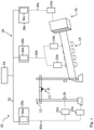
- Fig. 1 is a schematic illustration of an industrial control environment 10 in which the techniques according to the present disclosure may be employed.
- the industrial control environment 10 depicted in Fig. 1 is a factory environment in which goods are transported from a gantry crane 12 via a conveyor belt 14 to a packaging station 16, which are all connected and controlled by means of an industrial control network 18.
- an industrial control network 18 which is all connected and controlled by means of an industrial control network 18.
- this is merely one example chosen for illustration, and the techniques according to the present disclosure may be employed in a wide range of industrial control environments, from factory environments and chemical plants to applications in building or lighting automation.
- a first actuator unit 20a may be connected to the gantry crane 12 and may be adapted to control the movement of a hook assembly 22 of the gantry crane, so to place goods on the conveyor belt 14.
- a first sensor unit 24a may be connected to an infrared light barrier sensor 26, which may be adapted to sense the presence of humans or other obstacles in the operation path of the hook assembly 22, so to trigger an alarm signal and shut down the operation of the movable hook assembly 22 in case these obstacles may interfere with the safe operation of the gantry crane 12.
- the first actuator unit 20a and the first sensor unit 24a may be communicatively connected to a first industrial controller unit 28a by means of a first network 30a, such as a first field bus network.
- the first industrial controller unit 28a may run an industrial control program, such as in the form of a compiled industrial control program or ladder logic instructions, and may exchange messages with the first actuator unit 20a and the first sensor unit 24a via the first field bus network 30a in accordance with a first communication protocol, such as a communication protocol compliant with IEC 61784-3.
- the first industrial controller unit 28a may provide operation commands for an operation of the movable hook assembly 22 to the gantry crane 12 via the first field bus network 30a and the first actuator unit 20a.
- the first industrial controller unit 28a may receive control signals from the infrared light barrier sensor 26 via the first sensor unit 24a and the first field bus network 30a, and in response to the received sensor signals may send a command to the first actuator unit 20a to pause or change the movement of the hook assembly 22.
- the first actuator unit 20a and the first sensor unit 24a are shown as separate units. However, in some implementations the actuator units and sensor units may be combined into a common unit, and may in fact be integrated into the controlled machinery, such as the gantry crane 12. In general, there may be a larger number of actuator units and sensor units controlling different operations of the gantry crane 12.
- An operation of the conveyor belt 14 may be controlled similarly by means of a second actuator unit 20b that is adapted to actuate a driving roller of the conveyor belt 14 in response to driving signals, wherein the second actuator unit 20b receives the driving signals from a second industrial controller unit 28b via a second field bus network 30b according to a second communication protocol.
- a second sensor unit 24b may be connected to a sensor device (not shown) adapted to measure a speed of movement of the conveyor belt 14 and may provide corresponding sensor signals to the second industrial controller unit 28b via the second field bus network 30b.
- the second industrial controller unit 28b may process the sensor signals in a feedback loop to control the operation of the conveyor belt 14 by means of the second actuator unit 20b.
- a larger number of actuator units and/or sensor units may be connected to the second industrial controller unit 28b via the second field bus network 30b to control various aspects of the operation of the conveyor belt 14.
- a third actuator unit 20c may be adapted to control operation of the packaging station 16 in response to control signals, wherein the third actuator unit 20c receives the control signals from a third industrial controller unit 28c via a third field bus network 30c in accordance with a third communication protocol.
- the first industrial controller unit 28a, the second industrial controller unit 28b and the third industrial controller unit 28c may be connected among one another by means of an interconnection network 32, which may again be a field bus network, but could also be a different type of network, such as an Ethernet network.
- Router elements 36a, 36b, 36c may be provided in the respective industrial controller units 28a, 28b, 28c to route messages via the respective field bus networks 30a, 30b, 30c and/or the interconnection network 32.
- the interconnection network 32 and the field bus networks 30a, 30b, 30c may each form part of the industrial control network 18, which may also comprise any number of further machinery, industrial controller units, field bus networks, actuator units and/or sensor units beyond the equipment shown in Fig. 1 . Each of these units may be adapted to send and/or receive messages according to their respective designated communication protocol.
- the interconnection network 32 may allow the industrial controller units 28a, 28b, 28c to exchange industrial control programs, variables or files that may be required for the operation of the industrial control environment 10.
- the interconnection network 32 may also connect the industrial controller units 28a, 28b, 28c to a central programming and/or monitoring station 34, which may be employed by an operator to distribute industrial control programs or variables to the industrial controller units 28a, 28b, 28c, or to monitor an operation of the industrial controller units 28a, 28b, 28c or their associated machinery.
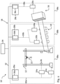
- the network devices, both senders and receivers (such as the industrial controller units 28a, 28b, 28c, actuator units 20a, 20b, 20c and sensor units 24a, 24b) need to be provided with unique and unambiguous addresses, which requires careful planning and maintenance of the respective sub-network 38a, 38b, 38c.
- Messages may also be exchanged across the boundaries of the sub-network 38a, 38b, 38c, such as via the interconnection network 32. This may sometimes happen inadvertently, for instance when messages are mis-routed in a router element 36a, 36b, 36c that has not been configured correctly.
- the mis-routed message may be received and processed by some receiver device that happens to share the same receiver address in the second sub-network 38b or the third sub-network 38c, and may trigger an unwanted response in that other sub-network.
- This error may be particularly critical in safety-relevant networks, such as networks specified in IEC 61784-3: "Industrial communication networks - Profiles - Part 3: Functional safety field buses ".
- cross-communication across different sub-network 38a, 38b, 38c via the interconnection network 32 may even be desirable. Again, this may be particularly important in safety-critical applications. For instance, in case the infrared light barrier sensor 26 detects an object moving in the operation path of the gantry crane 12, it may be desirable to not only shut down operation of the gantry crane 12, but also stop operation of the conveyor belt 14 automatically and simultaneously. This requires the respective message to be transferred from the first sensor unit 24a via the first field bus network 30a, the first industrial controller unit 28a, the interconnection network 32, the second industrial controller unit 28b, the second field bus network 30b to the second actuator unit 20b.
- the techniques according to the present disclosure address these challenges by means of additional encoding/decoding of addresses of a given address space, such as an address space corresponding to one of the sub-network 38a, 38b, 38c. This may allow providing unique addresses across a plurality of the sub-network 38a, 38b, 38c. In particular, each designated address space or sub-network 38a, 38b, 38c may be assigned its own designated encoding/decoding operation.
- the techniques of the present disclosure may allow a given receiver device to identify a message that has been mis-routed from a different sub-network, and hence may prevent the receiver device from an undesired and possibly safety-critical operation in response to the mis-routed message.
- the techniques of the present disclosure may also accommodate cross-communication between sender/receiver devices in different sub-network 38a, 38b, 38c.
- Fig. 3 is a schematic illustration of an industrial control sender device 40 according to an embodiment.
- any of the network devices described above with reference to Figs. 1 and 2 that is adapted to send messages over the industrial control network 18 can be considered an example of an industrial control sender device 40 as shown Fig. 3 .
- industrial control sender device 40 can be any of the actuator units 20a, 20b, 20c, sensor units 24a, 24b, and industrial controller units 28a, 28b, 28c.
- the industrial control sender device 40 is adapted to communicate with an industrial control receiver device 42 via the industrial control network 18 according to a designated communication protocol, such as FSoE ("Fail Safe over EtherCAT") as specified in IEC 61784-3-12.
- the industrial control receiver device 42 may be another network device within the same sub-network 38a, 38b, 38c, or even within a sub-network 38a, 38b, 38c that differs from the sub-network where the industrial control sender device 40 is located.
- any of the network devices described above with reference to Figs. 1 and 2 that is adapted to receive messages over the industrial control network 18 can be considered an example of an industrial control receiver device 42.
- industrial control receiver device 42 can be any of the actuator units 20a, 20b, 20c, sensor units 24a, 24b, or industrial controller units 28a, 28b, 28c.
- the industrial control sender device 40 as illustrated in Fig. 3 comprises a message generation unit 44 adapted to generate a first message to be sent to the first industrial control receiver device 42, wherein the first message complies with the communication protocol and comprises a first functional data string and a first payload data string.
- the first functional data string may comprise a protocol header string and an address string according to the underlying communication protocol, such as FSoE.
- the address string may comprise a target address designating the industrial control receiver device 42 for which the message/ payload data is intended.
- the payload data string may comprise the data to be transferred to the industrial control receiver device 42, such as a command string for actuating a machinery communicatively coupled to the industrial control receiver device 42.
- the industrial control sender device 40 additionally comprises an encoder unit 46 adapted to encode at least part of the first functional data string according to a first encoding algorithm to generate a first encoded message comprising a first encoded functional data string.
- the industrial control sender device 40 further comprises a sender unit 48 adapted to send the first encoded message comprising the first encoded functional data string to the industrial control receiver device 42 via the industrial control network 18, such as via any of the field bus networks 30a, 30b, 30c described above with reference to Figs. 1 and 2 .
- the first encoding algorithm may operate on the address string only, while leaving the payload data string unencoded.
- the first encoding algorithm may convert the address string of the target industrial control receiver device 42 into an encoded address string that no longer complies with the underlying communication protocol, and in particular no longer represents a valid target address according to the communication protocol.
- the message cannot be identified by that foreign receiver device as a valid instruction, because its header string and/or address string do not comply with the underlying communication protocol. This may prevent the mis-routed message from triggering any undesirable operation at the foreign receiver device.
- the foreign receiver device upon receiving the mis-routed message, may enter into a safe state, and may trigger a notification to operating personnel, such as to the central programming and/or monitoring station 34. Alternatively, as will be described further below, the foreign receiver device may simply filter out the mis-routed message.
- Fig. 4 is a schematic illustration of an industrial control receiver device 42 according to an embodiment.
- the industrial control receiver device 42 is adapted to communicate with a first industrial control sender device, such as the industrial control sender device 40 described above with reference to Fig. 3 , via the industrial control network 18 according to the communication protocol.
- the industrial control receiver device 42 comprises a receiver unit 50 adapted to receive a first message from the first industrial control sender device 40 via the industrial control network 18, the first message comprising a first functional data string and a first payload data string.
- the first message may be the first encoded message comprising the first encoded functional data string generated by the industrial control sender device 40 as described above with reference to Fig. 3 .
- the industrial control receiver device 42 additionally comprises a decoder unit 52 adapted to decode the first functional data string in accordance with a first decoding algorithm to generate a first decoded message comprising a first decoded functional data string. While the first message may be a message that does not comply with the communication protocol, the first decoding algorithm may convert the first functional data string into a first decoded message comprising a first decoded functional data string that complies with the communication protocol, for instance represents a valid target address and can therefore be processed by the industrial control receiver device 42 in accordance with the communication protocol.
- the industrial control sender device 40 and the industrial control receiver device 42 may exchange messages according to the underlying (safety-relevant) communication protocol, whereas mis-routed messages from other sender devices can be identified as foreign messages, and are prevented from wreaking any havoc in the industrial control environment 10.
- Fig. 5 is a schematic diagram that illustrates the interplay of an industrial control sender device 40a and several industrial control receiver devices 42a, 42b that are interconnected via the industrial control network 18 in an industrial control environment 10 according to an embodiment.
- the industrial control sender device 40a and a first industrial control receiver device 42a may be associated with a first machinery in the industrial control environment 10 in a first sub-network 38a, as described above with reference to Figures 1 and 2 .
- a second industrial control receiver device 42b may be associated with a second machinery in the industrial control environment 10 in a second sub-network 38b that is different from the first sub-network 38a.
- the industrial control sender device 40a may be an industrial control sender device 40 as described above with reference to Fig. 3 , in particular may be any of the network devices 20a, 24a, 28a described above with reference to Figures 1 and 2 .
- the industrial control receiver devices 42a, 42b may be an industrial control receiver device 42 as described above with reference to Fig. 4 , and in particular may be any of the network devices 20a, 24a, 28a or 20b, 24b, 28b, respectively, as described above with reference to Figures 1 and 2 .
- the industrial control sender device 40a may comprise a message generation unit 44a adapted to generate a message based on a set of payload data that is to be sent to the first receiver device 42a, wherein the message is generated in a protocol stack in accordance with the underlying communication protocol.
- the message may comprise the payload data as well as a functional data string comprising header and target address information in accordance with the communication protocol.
- the industrial control sender device 40a additionally comprises an encoder unit 46a implementing a first encoding algorithm to convert the message into a first encoded message comprising a first encoded functional data string, and a first sender unit 48a adapted to send the first encoded message comprising the first encoded functional data string via the industrial control network 18 to the first receiver device 42a.
- the first industrial control receiver device 42a comprises a first receiver unit 50a adapted to receive the first encoded message comprising the first encoded functional data string, and forward it to a first decoder unit 52a.
- the first decoder unit 52a implements a first decoding algorithm, which may be an inverse operation of the first encoding algorithm implemented in the first encoder unit 46a.
- the first decoder unit 52a thereby converts the first encoded message comprising the first encoded functional data string back into the original message prepared by the message generation unit 44a, comprising the original functional data string with the original address information that complies with the communication protocol. This allows the protocol stack in the first industrial control receiver device 42a to correctly identify and process the decoded message, and to retrieve the payload data.
- the first encoded message may also be received at the second industrial control receiver device 42b by means of a second receiver unit 50b, such as due to a mis-routing of the message.
- the second receiver unit 50b forwards the received first encoded message to a second decoder unit 52b, which may be adapted to implement a second decoding algorithm that differs from the first decoding algorithm implemented in the first decoder unit 52a.
- the second decoding algorithm may not be the inverse of the first encoding algorithm, and hence may convert the first encoded message comprising the first encoded functional data string into a message that does not comply with the underlying communication protocol.
- the protocol stack of the second industrial control receiver device 42b will hence identify the message as faulty, and may switch into a failsafe state.
- the protocol stack of an industrial control receiver device 42' that does not implement a decoder unit may also identify the received message as faulty, and may likewise switch into a failsafe state.
- the techniques according to the present disclosure hence permit a partitioning the industrial control network 18 into separate sub-networks with different and disjoint address spaces generated by means of distinct encoder/decoder pairs, thereby allowing mis-routed safety-relevant messages to be identified and the corresponding network devices to be switched into a failsafe state.
- the network devices In embodiments where data is also to be exchanged between different machines/sub-networks in the higher-level network on the basis of the same underlying communication protocol (e.g. for the implementation of safe network variables for inter-machine communication), the network devices also receive messages that cannot be interpreted by their protocol stacks, such as their field bus stacks responsible for the physical I/Os. As described above with reference to Fig. 5 , the machines would thus switch to a failsafe state whenever such a message is received, and productive operation of the machines would hardly be feasible.
- the industrial control receiver device may further comprise a comparison unit adapted to compare the respective first decoded functional data string with at least a predefined functional data string.
- the industrial control receiver device may be adapted to process the decoded message only if the comparison reveals that the first decoded functional data string matches a predefined functional data string, such as an expected functional data string.
- the comparison unit may be implemented as a filter which is adapted to accept and pass messages that comply with the communication protocol, and to reject messages that do not comply with the communication protocol without passing them on to the communication stack of the respective industrial control receiver device.
- FIG. 6 An example for an implementation involving filters is schematically illustrated in Fig. 6 , which is generally similar to the architecture illustrated in Fig. 5 described above, and corresponding devices share the same reference signs.
- the first industrial control receiver device 42a and the second industrial control receiver device 42b additionally each comprise a respective filter unit 54a, 54b downstream of the respective decoder units 52a and 52b, respectively.
- the decoded message will comprise a functional data string that complies with the communication protocol, and the first filter unit 54a will pass on that message to the respective protocol stack.
- the second filter unit 54b will reject the corresponding message, which will hence not be forwarded to the respective protocol stack and will not trigger the second industrial control receiver device 42b to move into a failsafe state, thereby ensuring the continued operation of the associated machinery.
- Fig. 6 shows the comparison unit/filter unit 54a, 54b as stand-alone units. However, in other embodiments the comparison unit/filter unit 54a, 54b may also be integrated into the respective decoder unit 52a, 52b.
- comparison unit/filter unit 54a, 54b For the comparison unit/filter unit 54a, 54b to be able to identify a message to be rejected, it should be able to distinguish between messages that are falsified and those that are simply not intended for the downstream receiver. It is therefore advisable not to encode the I/O payload data or its protection, but only protocol-flow related information in the message.
- the command byte in the message header may be encoded in a way that the encoded command byte does not correspond to a valid command byte.
- a finite set of N pairs encoding algorithms/decoding algorithms may be selected such that:
- the n-th encoding operation may be chosen as the n-fold Rotate Left operation on the command byte X:
- any industrial control receiver device in the network may decide, on the basis of the decoded value of the command byte, whether the message was intended for that particular industrial control receiver device. This is only the case if it receives a value X D with X D ⁇ CMD FSoE for the FSoE command.
- Table 1 illustrates the respective disjoint address spaces that result for the values from CMD FSoE as well as the encoder C 1 and two decoders D 1 and D 3 , which decode the C 1 -encoded and C 0 -encoded (i.e. un-encoded) values.
- the additional encoders/decoders thereby effectively enhance the logical address width of the underlying basic communication protocol, making it possible for FSoE, for example, to have more than 65,535 nodes/network devices throughout the network.
- the address space for safe communication can therefore be extended N -fold. This may also allow tailored cross-communication between different sub-networks with different distinct address spaces, as will now be described in additional detail with reference to the embodiment illustrated in Fig. 7 .
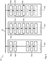
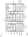
- the industrial control environment 10 illustrated in Fig. 7 comprises three sub-networks 38a, 38b, 38c that are coupled by means of an interconnection network 32, similar to the architecture described above with reference to Figures 1 and 2 .
- Each of the sub-networks 38a, 38b, 38c comprises a respective industrial controller unit 28a, 28b, 28c adapted to communicate with a plurality of first input/output slaves 56a1,..., 56an, second input/output slaves 56b1, ..., 56bn, and third input/output slaves 56c1, ..., 56cn, respectively, (for some integer number n) via respective field bus networks 30a, 30b, 30c.
- each of the first input/output slaves 56a1,..., 56an, second input/output slaves 56b1, ..., 56bn, and third input/output slaves 56c1, ..., 56cn may be an actuator unit 20a, 20b, 20c or a sensor unit 24a, 24b as described above with reference to Figures 1 and 2 .
- the example of Fig. 7 assumes that each of the sub-networks 38a, 38b, 38c has the same number n of input/output slaves, but the disclosure is not so limited, and in other examples two or more of the sub-networks 38a, 38b, 38c may have a different number of input/output slaves.
- Each of the first input/output slaves 56a1,..., 56an may have their unique addresses within the first sub-network 38a, and similarly for the second input/output slaves 56b1, ..., 56bn within the second sub-network 38b and the third input/output slaves 56c1, ..., 56cn within the third sub-network 38c.
- the first industrial controller unit 28a comprises a first input/output master unit 58a for communication with each of the first input/output slaves 56a1,..., 56an via the first field bus network 30a.
- the first input/output master unit 58a may combine the functionality of an industrial control sender device 40 and an industrial control receiver device 42 as described above with reference to Figures 1 to 6 .
- the second industrial controller unit 28b comprises a second input/output master unit 58b for communication with each of the second input/output slaves 56b1,..., 56bn via the second field bus network 30b
- the third industrial controller unit 28c comprises a third input/output master unit 58c for communication with each of the third input/output slaves 56c1,..., 56cn via the third field bus network 30c.
- the second input/output master unit 58b and the third input/output master unit 58c generally correspond to the first input/output master unit 58a, but implement different pairs of encoding/decoding algorithms.
- the first input/output master unit 58a and the corresponding first input/output slaves 56a1, ...., 56an may implement a first pair C 1 / D 1 of encoding/decoding algorithms as described with reference to Eqs. (1) to (6) above, whereas the second input/output master unit 58b and the corresponding second input/output slaves 56b1, ...., 56bn may implement a second pair C 3 / D 3 of encoding/decoding algorithms, and the third input/output master unit 58c and the corresponding third input/output slaves 56c1, ...., 56cn may implement a third pair C 0 / D 0 of encoding/decoding algorithms.
- the third pair C 0 / D 0 implements the identity operation, and hence corresponds to a state-of-the-art architecture. As described with reference to Eqs. (1) to (6) above, this configuration will ensure distinct and disjoint address spaces in each of the sub-networks 38a, 38b, 38c.
- the first industrial controller unit 28a may comprise a netvar master unit 60a
- the second industrial controller unit 28b may comprise a corresponding netvar slave unit 60b.
- the netvar master unit 60a and the netvar slave unit 60b may both combine the functionality of an industrial control sender device 40 and an industrial control receiver device 42 as described above with reference to Figures 1 to 6 , with a corresponding pair C 2 / D 2 of encoding/decoding algorithms as described with reference to Eqs. (1) to (6) above. This may allow the first industrial controller unit 28a and the second industrial controller unit 28b to cross-communicate safety-relevant data via global network variables, such as via the interconnection network 32.
- Table 5 shows the processing of a valid communication between the netvar master unit 60a in the first sub-network 38a and the corresponding netvar slave unit 60b in the second sub-network 38b for the minimal and maximal values of CMD FSoE .
- Table 5 Netvar-Master 1 Netvar-Slave 2 FSoE Stack ⁇ Encoder C 2 ⁇ Decoder D 2 ⁇ Filter ⁇ FSoE Stack X
- X C ROL(X, 2)
- X D ROR( X C , 2) X D ⁇ CMD FSoE ? X 0x08 0x20 0x08 Yes 0x08 0x64 0x91 0x64 Yes 0x64
- Table 6 shows the processing of an invalid communication between the netvar master unit 60a in the first sub-network 38a and an input/output slave 56b1 in the second sub-network 38b, again for the minimal and maximal values of CMD FSoE .
- Table 6 Netvar-Master 1 E/A-Slave 2 FSoE Stack ⁇ Encoder C 2 ⁇ Decoder D 3 ⁇ Filter ⁇ FSoE Stack X
- X C ROL(X, 2)
- X D ROR( X C 3) X D ⁇ CMD FSoE ? X 0x08 0x20 0x04 No No call 0x64 0x91 0x32 No No call
- the project engineer merely has to guarantee the uniqueness of the addresses in the new machine, as long as he selects an encoder that is unique in the system.
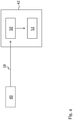
- Fig. 8 is a flow diagram illustrating a method for communicating with a first industrial control receiver device in an industrial control network by means of a communication protocol, according to an embodiment.
- a first message to be sent to the first industrial control receiver device is generated, wherein the first message complies with the communication protocol and comprises a first functional data string and a first payload data string.
- a second step S12 at least part of the first functional data string is encoded according to a first encoding algorithm to generate a first encoded message comprising a first encoded functional data string.
- the first encoded message comprising the first encoded functional data string is sent to the first industrial control receiver device via the industrial control network.
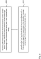
- Fig. 9 is a flow diagram illustrating a method for communicating with a first industrial control sender device in an industrial control network by means of the communication protocol, according to an embodiment.
- a first message is received from the first industrial control sender device via the industrial control network, the first message comprising a first functional data string and a first payload data string.
- a second step S22 the first functional data string is decoded in accordance with a first decoding algorithm to generate a first decoded message comprising a first decoded functional data string.
Landscapes
- Engineering & Computer Science (AREA)
- Computer Networks & Wireless Communication (AREA)
- Signal Processing (AREA)
- Health & Medical Sciences (AREA)
- Computing Systems (AREA)
- General Health & Medical Sciences (AREA)
- Medical Informatics (AREA)
- Small-Scale Networks (AREA)
- Programmable Controllers (AREA)
Priority Applications (1)
| Application Number | Priority Date | Filing Date | Title |
|---|---|---|---|
| EP20189664.4A EP3952245B1 (fr) | 2020-08-05 | 2020-08-05 | Adressage de dispositifs dans les réseaux de contrôle industriel |
Applications Claiming Priority (1)
| Application Number | Priority Date | Filing Date | Title |
|---|---|---|---|
| EP20189664.4A EP3952245B1 (fr) | 2020-08-05 | 2020-08-05 | Adressage de dispositifs dans les réseaux de contrôle industriel |
Publications (3)
| Publication Number | Publication Date |
|---|---|
| EP3952245A1 true EP3952245A1 (fr) | 2022-02-09 |
| EP3952245C0 EP3952245C0 (fr) | 2025-10-08 |
| EP3952245B1 EP3952245B1 (fr) | 2025-10-08 |
Family
ID=71950548
Family Applications (1)
| Application Number | Title | Priority Date | Filing Date |
|---|---|---|---|
| EP20189664.4A Active EP3952245B1 (fr) | 2020-08-05 | 2020-08-05 | Adressage de dispositifs dans les réseaux de contrôle industriel |
Country Status (1)
| Country | Link |
|---|---|
| EP (1) | EP3952245B1 (fr) |
Citations (2)
| Publication number | Priority date | Publication date | Assignee | Title |
|---|---|---|---|---|
| US20200022022A1 (en) * | 2017-03-10 | 2020-01-16 | Convida Wireless, Llc | Dynamic header compression for constrained networks |
| WO2020125988A1 (fr) * | 2018-12-20 | 2020-06-25 | Huawei Technologies Co., Ltd. | Dispositif et procédé de compression de trame flexible |
-
2020
- 2020-08-05 EP EP20189664.4A patent/EP3952245B1/fr active Active
Patent Citations (2)
| Publication number | Priority date | Publication date | Assignee | Title |
|---|---|---|---|---|
| US20200022022A1 (en) * | 2017-03-10 | 2020-01-16 | Convida Wireless, Llc | Dynamic header compression for constrained networks |
| WO2020125988A1 (fr) * | 2018-12-20 | 2020-06-25 | Huawei Technologies Co., Ltd. | Dispositif et procédé de compression de trame flexible |
Non-Patent Citations (2)
| Title |
|---|
| CMCC: "Enhancement for Time-Sensitive Networking", vol. RAN WG2, no. Chengdu, China; 20181008 - 20181012, 28 September 2018 (2018-09-28), XP051524625, Retrieved from the Internet <URL:http://www.3gpp.org/ftp/tsg%5Fran/WG2%5FRL2/TSGR2%5F103bis/Docs/R2%2D1815270%2Ezip> [retrieved on 20180928] * |
| ERICSSON: "[104#37][NR/IIoT] Ethernet Header Compression email discussion report, TP", vol. RAN WG2, no. Athens, Greece; 20190225 - 20190301, 1 March 2019 (2019-03-01), XP051603664, Retrieved from the Internet <URL:http://www.3gpp.org/ftp/tsg%5Fran/WG2%5FRL2/TSGR2%5F105/Docs/R2%2D1902355%2Ezip> [retrieved on 20190301] * |
Also Published As
| Publication number | Publication date |
|---|---|
| EP3952245C0 (fr) | 2025-10-08 |
| EP3952245B1 (fr) | 2025-10-08 |
Similar Documents
| Publication | Publication Date | Title |
|---|---|---|
| US8055814B2 (en) | Universal safety I/O module | |
| JP7792193B2 (ja) | プロセス制御入力/出力デバイスにおける多数の通信物理層およびプロトコルの統合 | |
| EP2302841B2 (fr) | Dispositif de communication orientée vers la sécurité dans le réseau de communication d'une installation d'automatisation | |
| US8509927B2 (en) | Control system for controlling safety-critical processes | |
| US10127163B2 (en) | Control device for controlling a safety device, and use of an IO link for transmission of a safety protocol to a safety device | |
| AU2015298203B2 (en) | System and method for controller redundancy and controller network redundancy with EtherNet/IP I/O | |
| US8549136B2 (en) | System for operating at least one non-safety-critical and at least one safety-critical process | |
| US10732594B2 (en) | Method for operating safety control in an automation network, and automation network having such safety control allowing mixed safety integrity levels | |
| AU2022201517B2 (en) | Method and system for parallel redundancy protocol in connected networks | |
| US20170242693A1 (en) | Safety monitoring device, network system and safety monitoring method | |
| US7715932B2 (en) | Method and apparatus for controlling a safety-critical process | |
| US10126727B2 (en) | Method and system for safely switching off an electrical load | |
| EP2656581B1 (fr) | Dispositif de couplage réseau et procédé de transmission pour réseaux de données par paquets dans des systèmes de commande de processus ou des systèmes de contrôle/commande de l'exploitation | |
| DE102006054124B4 (de) | Verfahren und System zur sicheren Datenübertragung | |
| CN103034162B (zh) | 用于控制可编程控制器的通信输入的计算机执行的方法 | |
| EP2784988B1 (fr) | Module d'interface de communication pour un dispositif de commande modulaire d'un système industriel d'automatisation | |
| EP3952245B1 (fr) | Adressage de dispositifs dans les réseaux de contrôle industriel | |
| EP3189645A1 (fr) | Transmission de données entre un producteur sécurisé et au moins un consommateur sécurisé | |
| US10649932B2 (en) | Safety-oriented electrical controller and controller system | |
| JP4574480B2 (ja) | 自動化バス・システムを安全に切り換えるための方法および装置 | |
| EP4149063B1 (fr) | Procédé et appareil pour un trajet de communication alternatif pour réseaux connectés | |
| EP4607860A1 (fr) | Procédé de transmission de trames de commande selon un protocole de redondance et dispositif de réseau | |
| de Andrade et al. | Case Study: Retrofitting in a Bearing Plate Machining and Assembly Line | |
| Piggin | A fieldbus for machine safety |
Legal Events
| Date | Code | Title | Description |
|---|---|---|---|
| PUAI | Public reference made under article 153(3) epc to a published international application that has entered the european phase |
Free format text: ORIGINAL CODE: 0009012 |
|
| STAA | Information on the status of an ep patent application or granted ep patent |
Free format text: STATUS: THE APPLICATION HAS BEEN PUBLISHED |
|
| AK | Designated contracting states |
Kind code of ref document: A1 Designated state(s): AL AT BE BG CH CY CZ DE DK EE ES FI FR GB GR HR HU IE IS IT LI LT LU LV MC MK MT NL NO PL PT RO RS SE SI SK SM TR |
|
| STAA | Information on the status of an ep patent application or granted ep patent |
Free format text: STATUS: REQUEST FOR EXAMINATION WAS MADE |
|
| 17P | Request for examination filed |
Effective date: 20220808 |
|
| RBV | Designated contracting states (corrected) |
Designated state(s): AL AT BE BG CH CY CZ DE DK EE ES FI FR GB GR HR HU IE IS IT LI LT LU LV MC MK MT NL NO PL PT RO RS SE SI SK SM TR |
|
| REG | Reference to a national code |
Ref country code: DE Ref legal event code: R079 Free format text: PREVIOUS MAIN CLASS: H04L0029080000 Ipc: H04L0012460000 Ref country code: DE Ref legal event code: R079 Ref document number: 602020060027 Country of ref document: DE Free format text: PREVIOUS MAIN CLASS: H04L0029080000 Ipc: H04L0012460000 |
|
| GRAP | Despatch of communication of intention to grant a patent |
Free format text: ORIGINAL CODE: EPIDOSNIGR1 |
|
| STAA | Information on the status of an ep patent application or granted ep patent |
Free format text: STATUS: GRANT OF PATENT IS INTENDED |
|
| RIC1 | Information provided on ipc code assigned before grant |
Ipc: H04L 12/403 20060101ALI20250424BHEP Ipc: H04L 69/04 20220101ALI20250424BHEP Ipc: H04L 45/74 20220101ALI20250424BHEP Ipc: H04L 67/12 20220101ALI20250424BHEP Ipc: H04L 12/46 20060101AFI20250424BHEP |
|
| INTG | Intention to grant announced |
Effective date: 20250507 |
|
| GRAS | Grant fee paid |
Free format text: ORIGINAL CODE: EPIDOSNIGR3 |
|
| GRAA | (expected) grant |
Free format text: ORIGINAL CODE: 0009210 |
|
| STAA | Information on the status of an ep patent application or granted ep patent |
Free format text: STATUS: THE PATENT HAS BEEN GRANTED |
|
| AK | Designated contracting states |
Kind code of ref document: B1 Designated state(s): AL AT BE BG CH CY CZ DE DK EE ES FI FR GB GR HR HU IE IS IT LI LT LU LV MC MK MT NL NO PL PT RO RS SE SI SK SM TR |
|
| REG | Reference to a national code |
Ref country code: GB Ref legal event code: FG4D Ref country code: CH Ref legal event code: F10 Free format text: ST27 STATUS EVENT CODE: U-0-0-F10-F00 (AS PROVIDED BY THE NATIONAL OFFICE) Effective date: 20251008 |
|
| REG | Reference to a national code |
Ref country code: DE Ref legal event code: R096 Ref document number: 602020060027 Country of ref document: DE |
|
| REG | Reference to a national code |
Ref country code: IE Ref legal event code: FG4D |
|
| U01 | Request for unitary effect filed |
Effective date: 20251017 |
|
| U07 | Unitary effect registered |
Designated state(s): AT BE BG DE DK EE FI FR IT LT LU LV MT NL PT RO SE SI Effective date: 20251023 |
|
| PG25 | Lapsed in a contracting state [announced via postgrant information from national office to epo] |
Ref country code: ES Free format text: LAPSE BECAUSE OF FAILURE TO SUBMIT A TRANSLATION OF THE DESCRIPTION OR TO PAY THE FEE WITHIN THE PRESCRIBED TIME-LIMIT Effective date: 20251008 |
|
| PG25 | Lapsed in a contracting state [announced via postgrant information from national office to epo] |
Ref country code: NO Free format text: LAPSE BECAUSE OF FAILURE TO SUBMIT A TRANSLATION OF THE DESCRIPTION OR TO PAY THE FEE WITHIN THE PRESCRIBED TIME-LIMIT Effective date: 20260108 |
|
| PG25 | Lapsed in a contracting state [announced via postgrant information from national office to epo] |
Ref country code: HR Free format text: LAPSE BECAUSE OF FAILURE TO SUBMIT A TRANSLATION OF THE DESCRIPTION OR TO PAY THE FEE WITHIN THE PRESCRIBED TIME-LIMIT Effective date: 20251008 |
|
| PG25 | Lapsed in a contracting state [announced via postgrant information from national office to epo] |
Ref country code: RS Free format text: LAPSE BECAUSE OF FAILURE TO SUBMIT A TRANSLATION OF THE DESCRIPTION OR TO PAY THE FEE WITHIN THE PRESCRIBED TIME-LIMIT Effective date: 20260108 |
|
| PG25 | Lapsed in a contracting state [announced via postgrant information from national office to epo] |
Ref country code: IS Free format text: LAPSE BECAUSE OF FAILURE TO SUBMIT A TRANSLATION OF THE DESCRIPTION OR TO PAY THE FEE WITHIN THE PRESCRIBED TIME-LIMIT Effective date: 20260208 |
|
| PG25 | Lapsed in a contracting state [announced via postgrant information from national office to epo] |
Ref country code: PL Free format text: LAPSE BECAUSE OF FAILURE TO SUBMIT A TRANSLATION OF THE DESCRIPTION OR TO PAY THE FEE WITHIN THE PRESCRIBED TIME-LIMIT Effective date: 20251008 |