EP3952505A1 - Benutzervorrichtung und basisstationsvorrichtung - Google Patents
Benutzervorrichtung und basisstationsvorrichtung Download PDFInfo
- Publication number
- EP3952505A1 EP3952505A1 EP19921568.2A EP19921568A EP3952505A1 EP 3952505 A1 EP3952505 A1 EP 3952505A1 EP 19921568 A EP19921568 A EP 19921568A EP 3952505 A1 EP3952505 A1 EP 3952505A1
- Authority
- EP
- European Patent Office
- Prior art keywords
- user equipment
- base station
- dci
- transmission
- downlink shared
- Prior art date
- Legal status (The legal status is an assumption and is not a legal conclusion. Google has not performed a legal analysis and makes no representation as to the accuracy of the status listed.)
- Withdrawn
Links
Images




Classifications
-
- H—ELECTRICITY
- H04—ELECTRIC COMMUNICATION TECHNIQUE
- H04W—WIRELESS COMMUNICATION NETWORKS
- H04W72/00—Local resource management
- H04W72/20—Control channels or signalling for resource management
- H04W72/23—Control channels or signalling for resource management in the downlink direction of a wireless link, i.e. towards a terminal
- H04W72/232—Control channels or signalling for resource management in the downlink direction of a wireless link, i.e. towards a terminal the control data signalling from the physical layer, e.g. DCI signalling
-
- H—ELECTRICITY
- H04—ELECTRIC COMMUNICATION TECHNIQUE
- H04L—TRANSMISSION OF DIGITAL INFORMATION, e.g. TELEGRAPHIC COMMUNICATION
- H04L5/00—Arrangements affording multiple use of the transmission path
- H04L5/0091—Signalling for the administration of the divided path, e.g. signalling of configuration information
-
- H—ELECTRICITY
- H04—ELECTRIC COMMUNICATION TECHNIQUE
- H04B—TRANSMISSION
- H04B7/00—Radio transmission systems, i.e. using radiation field
- H04B7/02—Diversity systems; Multi-antenna system, i.e. transmission or reception using multiple antennas
- H04B7/022—Site diversity; Macro-diversity
- H04B7/024—Co-operative use of antennas of several sites, e.g. in co-ordinated multipoint or co-operative multiple-input multiple-output [MIMO] systems
-
- H—ELECTRICITY
- H04—ELECTRIC COMMUNICATION TECHNIQUE
- H04B—TRANSMISSION
- H04B7/00—Radio transmission systems, i.e. using radiation field
- H04B7/02—Diversity systems; Multi-antenna system, i.e. transmission or reception using multiple antennas
- H04B7/04—Diversity systems; Multi-antenna system, i.e. transmission or reception using multiple antennas using two or more spaced independent antennas
- H04B7/06—Diversity systems; Multi-antenna system, i.e. transmission or reception using multiple antennas using two or more spaced independent antennas at the transmitting station
- H04B7/0686—Hybrid systems, i.e. switching and simultaneous transmission
- H04B7/0691—Hybrid systems, i.e. switching and simultaneous transmission using subgroups of transmit antennas
-
- H—ELECTRICITY
- H04—ELECTRIC COMMUNICATION TECHNIQUE
- H04B—TRANSMISSION
- H04B7/00—Radio transmission systems, i.e. using radiation field
- H04B7/02—Diversity systems; Multi-antenna system, i.e. transmission or reception using multiple antennas
- H04B7/04—Diversity systems; Multi-antenna system, i.e. transmission or reception using multiple antennas using two or more spaced independent antennas
- H04B7/08—Diversity systems; Multi-antenna system, i.e. transmission or reception using multiple antennas using two or more spaced independent antennas at the receiving station
- H04B7/0868—Hybrid systems, i.e. switching and combining
- H04B7/0874—Hybrid systems, i.e. switching and combining using subgroups of receive antennas
-
- H—ELECTRICITY
- H04—ELECTRIC COMMUNICATION TECHNIQUE
- H04L—TRANSMISSION OF DIGITAL INFORMATION, e.g. TELEGRAPHIC COMMUNICATION
- H04L5/00—Arrangements affording multiple use of the transmission path
- H04L5/003—Arrangements for allocating sub-channels of the transmission path
- H04L5/0032—Distributed allocation, i.e. involving a plurality of allocating devices, each making partial allocation
- H04L5/0035—Resource allocation in a cooperative multipoint environment
-
- H—ELECTRICITY
- H04—ELECTRIC COMMUNICATION TECHNIQUE
- H04W—WIRELESS COMMUNICATION NETWORKS
- H04W72/00—Local resource management
- H04W72/04—Wireless resource allocation
- H04W72/044—Wireless resource allocation based on the type of the allocated resource
- H04W72/046—Wireless resource allocation based on the type of the allocated resource the resource being in the space domain, e.g. beams
-
- H—ELECTRICITY
- H04—ELECTRIC COMMUNICATION TECHNIQUE
- H04W—WIRELESS COMMUNICATION NETWORKS
- H04W72/00—Local resource management
- H04W72/12—Wireless traffic scheduling
- H04W72/1263—Mapping of traffic onto schedule, e.g. scheduled allocation or multiplexing of flows
- H04W72/1273—Mapping of traffic onto schedule, e.g. scheduled allocation or multiplexing of flows of downlink data flows
-
- H—ELECTRICITY
- H04—ELECTRIC COMMUNICATION TECHNIQUE
- H04W—WIRELESS COMMUNICATION NETWORKS
- H04W72/00—Local resource management
- H04W72/20—Control channels or signalling for resource management
- H04W72/23—Control channels or signalling for resource management in the downlink direction of a wireless link, i.e. towards a terminal
-
- H—ELECTRICITY
- H04—ELECTRIC COMMUNICATION TECHNIQUE
- H04W—WIRELESS COMMUNICATION NETWORKS
- H04W72/00—Local resource management
- H04W72/20—Control channels or signalling for resource management
- H04W72/23—Control channels or signalling for resource management in the downlink direction of a wireless link, i.e. towards a terminal
- H04W72/231—Control channels or signalling for resource management in the downlink direction of a wireless link, i.e. towards a terminal the control data signalling from the layers above the physical layer, e.g. RRC or MAC-CE signalling
-
- Y—GENERAL TAGGING OF NEW TECHNOLOGICAL DEVELOPMENTS; GENERAL TAGGING OF CROSS-SECTIONAL TECHNOLOGIES SPANNING OVER SEVERAL SECTIONS OF THE IPC; TECHNICAL SUBJECTS COVERED BY FORMER USPC CROSS-REFERENCE ART COLLECTIONS [XRACs] AND DIGESTS
- Y02—TECHNOLOGIES OR APPLICATIONS FOR MITIGATION OR ADAPTATION AGAINST CLIMATE CHANGE
- Y02D—CLIMATE CHANGE MITIGATION TECHNOLOGIES IN INFORMATION AND COMMUNICATION TECHNOLOGIES [ICT], I.E. INFORMATION AND COMMUNICATION TECHNOLOGIES AIMING AT THE REDUCTION OF THEIR OWN ENERGY USE
- Y02D30/00—Reducing energy consumption in communication networks
- Y02D30/70—Reducing energy consumption in communication networks in wireless communication networks
Definitions
- the present invention relates to a user equipment and a base station device in a wireless communication system.
- New Radio also referred to as "5G" which is a successor system of Long Term Evolution (LTE)
- LTE Long Term Evolution
- an indication of information indicating a transmission configuration indicator state (TCI state) applied to downlink signal transmission is given from a base station device to a user equipment.
- the TCI state is information related to quasi co-location (QCL) and corresponds to, for example, a spatial reception parameter of an antenna port.
- the user equipment applies the TCI state and receives a downlink signal transmitted from the base station device (for example, Non-Patent Document 2).
- MIMO multiple-input and multiple-output
- the extension function of MIMO includes, for example, transmission in which a plurality of transmission reception points (TRPs) or panels are used.
- TRPs transmission reception points
- the present invention was made in light of the foregoing, and it is an object of the present invention to perform configurations of communication in which a plurality of TRPs or panels are used in a wireless communication system.
- a user equipment including a receiving unit that receives information related to a transmission configuration state of a downlink shared channel from a base station device, a 0139control unit that individually applies a configuration related to quasi co-location (QCL) to each of the downlink shared channels transmitted from a plurality of transmission reception points (TRPs) or panels on the basis of the information related to the transmission configuration state, and a communication unit that performs communication via the downlink shared channel to which the configurations related to the plurality of QCLs is individually applied is provided.
- QCL quasi co-location
- the existing technology is appropriately used for an operation of a wireless communication system of an embodiment of the present invention.
- the existing technology is, for example, the existing LTE but is not limited to the existing LTE.
- LTE used in this specification has a broad meaning including LTE-Advanced and schemes after LTE-Advanced (for example, NR) unless otherwise specified.
- a synchronization signal (SS), a primary SS (PSS), a secondary SS (SSS), a physical broadcast channel (PBCH), and a physical random access channel (PRACH) used in the existing LTE are used.
- SS synchronization signal
- PSS primary SS
- SSS secondary SS
- PBCH physical broadcast channel
- PRACH physical random access channel
- a duplex scheme may be a Time Division Duplex (TDD) scheme, may be a Frequency Division Duplex (FDD) scheme, or may be other schemes (for example, Flexible Duplex or the like).
- TDD Time Division Duplex
- FDD Frequency Division Duplex
- a radio parameter or the like when a radio parameter or the like is "configured”, it may mean that a predetermined value is pre-configured or may mean that a radio parameter indicated by a base station device 10 or a user equipment 20 may be configured.
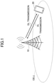
- Fig. 1 is a diagram for describing a wireless communication system in an embodiment of the present invention.
- the wireless communication system in the embodiment of the present invention includes a base station device 10 and a user equipment 20 as illustrated in Fig. 1 .
- a base station device 10 and one user equipment 20 are illustrated in Fig. 1 , this is an example, and a plurality of base station devices or a plurality of user equipments may be arranged.
- the base station device 10 is a communication device that provides one or more cells and performs wireless communication with the user equipment 20. Physical resources of wireless signals may be defined by a time domain and a frequency domain, the time domain may be defined by the number of OFDM symbols, and the frequency domain may be defined by the number of subcarriers or the number of resource blocks.
- the base station device 10 transmits a synchronization signal and system information to the user equipment 20.
- the synchronization signal is, for example, NR-PSS and NR-SSS.
- the system information is transmitted through an NR-PBCH and is also referred to as broadcast information. As illustrated in Fig.
- the base station device 10 transmits a control signal or data to the user equipment 20 by downlink (DL) and receives a control signal or data from the user equipment 20 by uplink (UL). Both the base station device 10 and the user equipment 20 can transmit and receive signals by performing beam forming. Both the base station device 10 and the user equipment 20 can apply communication according to multiple input multiple output (MIMO) to DL or UL. Further, both the base station device 10 and the user equipment 20 may perform communication via a secondary cell (SCell) and a primary cell (PCell) by carrier aggregation (CA).
- SCell secondary cell
- PCell primary cell
- CA carrier aggregation
- the user equipment 20 is a communication device with a wireless communication function such as a smartphone, a mobile phone, a tablet, a wearable terminal, or a M2M (machine-to-machine) communication module. As illustrated in Fig. 1 , the user equipment 20 uses various kinds of communication services provided by the wireless communication system by receiving a control signal or data from the base station device 10 by DL and transmitting a control signal or data to the base station device 10 by UL.
- a wireless communication function such as a smartphone, a mobile phone, a tablet, a wearable terminal, or a M2M (machine-to-machine) communication module.
- M2M machine-to-machine
- multi-TRP or multi-panel transmission of transmitting a physical downlink shared channel (PDSCH) from a plurality of TRPs or panels is under review.
- Scheduling and configurations by a single physical downlink control channel (PDCCH) for multi-TRP or multi-panel transmission is under review.
- the PDSCH transmitted from one or more TRPs or panels is scheduled through one PDCCH.
- DCI downlink control information
- an indication of the TCI states of TRP #1 and TRP #2 is given to the user equipment 20, and QCL assumption of the PDSCH is performed.
- an indication of a list of TCI states is given to the user equipment 20 for each cell and each bandwidth part (BWP) through "PDSCH-Config" which is RRC signaling. For example, 128 or more TCI states may be included in the list. Further, an indication of mapping between the TCI state included in the list and a DCI codepoint for indicating the TCI state is given to the user equipment 20 through media access control (MAC) signaling. For example, a maximum of the number of DCI codepoints for indicating the TCI state may be 8 or even greater.
- the MAC signaling is signaling by a MAC control element (CE).
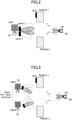
- Fig. 2 is a diagram for describing transmission in which a plurality of panels are used in an embodiment of the present invention.
- the base station device 10 performs transmission to the user equipment 20 using two panels (a panel 1 and a panel 2) in one TRP.
- a PDCCH including the DCI and a PDSCH 1 are transmitted from the panel 1, and a PDSCH 2 is transmitted from the panel 2. That is, in the case of scheduling and configurations by a single PDCCH, the user equipment 20 receives two PDSCHs on the basis of one DCI.
- Fig. 3 is a diagram for describing transmission in which a plurality of TRPs are used in an embodiment of the present invention.
- the base station device 10 performs transmission to the user equipment 20 using two TRPs (a TRP 1 and a TRP 2).
- a PDCCH including the DCI and a PDSCH 1 are transmitted from the TRP 1
- a PDSCH 2 is transmitted from the TRP 2. That is, in the case of scheduling and configurations by a single PDCCH, the user equipment 20 receives two PDSCHs on the basis of one DCI.
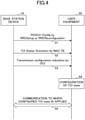
- Fig. 4 is a sequence diagram for describing an operation example in an embodiment of the present invention. An operation in which the TCI state is configured in the user equipment 20 will be described with reference to Fig. 4 .
- step S1 the base station device 10 transmits "PDSCH-Config" based on "RRCSetup” or "RRCReconfiguration” which is RRC signaling to the user equipment 20.
- "PDSCH-Config” includes, for example, a list including a maximum of 128 TCI states. More TCI states may be included in the list.
- the TCI state includes information about the QCL related to the spatial reception parameter.
- the QCL indicates that parameters can be regarded as being common between a reference signal including one or more synchronization signals or the like and a reference signal for data demodulation, and the following four types are specified (for example, Non-Patent Document) 3):
- step S2 the base station device 10 transmits "TCI States Activation" via the MAC CE to the user equipment 20.
- a plurality of TCI states included in the list received in step S1 are mapped to TCI states applied to the PDSCH of the serving cell corresponding to each DCI codepoint by the "TCI States Activation". That is, a candidate TCI state to be used among the TCI states included in the list is activated.
- the extended activation or deactivation is performed for the TCI state of the UE-specific PDSCH for multi-TRP or multi-panel transmission based on a single PDCCH, via the MAC CE.
- each TCI state of the PDSCH may be deactivated as the initial state after handover.
- a MAC entity indicates, to a lower layer, information related to activation or deactivation of the TCI state.
- "Multi-TRP or multi-panel" may be specified as a demodulation reference signal (DMRS) port group, may be specified as an antenna port group, may be specified as a group related to other reference signals, or may be specified as a TCI state group.
- DMRS demodulation reference signal
- the MAC CE that performs the extended activation or deactivation on the TCI state of the UE-specific PDSCH for multi-TRP or multi-panel transmission based on a single PDCCH is identified by a logical channel ID (LCID) included in a MAC PDU sub header.
- LCID logical channel ID
- the MAC CE configures activation for a maximum of 8 TCI states from a plurality of TCI states configured by information elements "tci-StatesToAddModList" and "tci-StatesToReleaseList" included in the RRC signaling "PDSCH-Config".
- one or two activated TCI states are mapped to a value of a "Transmission Configuration Indication" field of the DCI, that is, the DCI codepoint by the MAC CE.
- the TCI states activated by the MAC CE are mapped to the DCI codepoint in an ascending order. The mapping will be described later in detail.
- step S3 the base station device 10 transmits the "Transmission configuration indication" by the DCI to the user equipment 20.
- the user equipment 20 receives the DCI codepoint by "Transmission configuration indication”.
- the user equipment 20 specifies the TCI state corresponding to the DCI codepoint by mapping in step S2.
- step S4 the user equipment 20 configures a specified TCI state in the PDSCH. Then, the user equipment 20 and the base station device 10 execute communication to which the configured TCI state is applied.
- Fig. 5 illustrates a specification change example (1) related to an operation example in an embodiment of the present invention.
- the mapping by the MAC CE between the DCI codepoint and the TCI state included in the list in step S2 illustrated in Fig. 4 will be described with reference to Fig. 5 .
- Server Cell ID illustrated in Fig. 5 is an identifier of the serving cell to which the MAC CE is applied.
- BWP ID illustrated in Fig. 5 is an identifier of the DL-BWP to which the MAC CE is applied.
- TCI-StateId TCI state ID
- tci-StatesToAddModList TCI-StatesToAddModList
- tci-StatesToReleaseList RRC signaling "PDSCH-Config”
- activation or deactivation of the TCI state corresponding to the TCI state ID(i) is indicated.
- T i is ignored in a case in which there is no TCI state ID(i) configured by the information elements "tci-StatesToAddModList” and "tci-StatesToReleaseList" included in the RRC signaling "PDSCH-Config.”
- the number of activated TCI states may be up to 8 or even greater.
- the number of activated TCI states may be "2 ⁇ (the number of bits of the DCI Transmission Configuration Indication field) ⁇ (the number of TCI states of the PDSCH indicated by the single DCI)."
- Fig. 5 indicates a TCI state mapped to a DCI codepoint xxx applied to a first TRP or panel.
- a value "000” corresponds to a first TCI state activated by T i
- a value "001" corresponds to a second TCI state activated by T i , that is, the values correspond to the activated TCI states in the ascending order.
- P illustrated in Fig. 5 indicates that, in a case in which 1 is configured, there is a DCI codepoint xxx applied to the second TRP or panel. In a case in which 0 is configured in "P" illustrated in Fig. 5 , " 2 nd TCI State mapped to DCI codepoint xxx" is ignored. In other words, transmission is performed with one TRP or panel.
- FIG. 5 indicates the TCI state mapped to the DCI codepoint xxx applied to the second TRP or panel.
- a value "000” corresponds to a first TCI state activated by T i
- a value "001” corresponds to a second TCI state activated by T i , that is, the values correspond to the activated TCI states in the ascending order.
- the number of DCI codepoints according to the DCI Transmission Configuration Indication field may be 8 at maximum (that is, the field has 3 bits), may be greater (for example, the field has 4 bits), or may be less (for example, the field has 2 bits)).
- TCI State mapped to DCI codepoint xxx indicating the TCI state mapped to the DCI codepoint xxx applied to third and fourth TRPs or panels, or "P" indicating their presences may exist in the MAC CE.
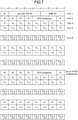
- Fig. 6 illustrates a specification change example (2) related to an operation example in an embodiment of the present invention.
- the mapping by the MAC CE between the DCI codepoint and the TCI state included in the list in step S2 illustrated in Fig. 4 will be described with reference to Fig. 6 .
- a value "000" of the DCI Transmission Configuration Indication field corresponds to an octet of "Oct N + 1" illustrated in Fig. 6
- a value "001" corresponds to an octet of "Oct N + 2" illustrated in Fig. 6 , that is, one octet corresponds to each DCI codepoint.
- AT 0 " illustrated in Fig. 6 corresponds to a first TCI state activated by T i
- a value "AT 1 " corresponds to a second TCI state activated by T i
- the TCI states activated by a maximum of two T i s may be mapped to each DCI codepoint, and further, in a case in which there are more than two TRPs or panels, the TCI states activated by a plurality of T i s may be mapped to each DCI codepoint.
- Which of the mapped TCI states corresponds to the first TRP or panel or which of the mapped TCI states corresponds to the second TRP or panel may be specified in advance or may be configured separately.
- Fig. 7 illustrates a specification change example (3) related to an operation example in an embodiment of the present invention.
- the mapping by the MAC CE between the DCI codepoint and the TCI state included in the list in step S2 illustrated in Fig. 4 will be described with reference to Fig. 7 .
- DCI codepoint illustrated in Fig. 7 indicates the value of the DCI Transmission Configuration Indication field to which the activated TCI state is mapped, that is, the codepoint.
- P illustrated in Fig. 7 indicates that, in a case in which 1 is configured, there is a second T i field applied to the second TRP or panel. In a case in which 0 is configured in "P" illustrated in Fig. 7 , the second T i field is not configured. In other words, transmission is performed with one TRP or panel.
- TCI-StateId TCI state ID
- tci-StatesToAddModList TCI-StatesToAddModList
- tci-StatesToReleaseList RRC signaling "PDSCH-Config”
- activation or deactivation of the TCI state corresponding to a TCI state ID(i) is indicated.
- T i is ignored in a case in which there is no TCI state ID(i) configured by the information elements "tci-StatesToAddModList” and "tci-StatesToReleaseList" included in the RRC signaling "PDSCH-Config".
- the TCI state applied to the first TRP or panel is indicated from a first T i field set
- the TCI state applied to the second TRP or panel is indicated from a second T i field set. That is, the TCI state activated by a bitmap is specified in the T i field set.
- the T i field set may include 128 or more TCI states.
- the number of "DCI codepoints" may be 8 indicated by 3 bits or may be a large number indicated by more bits. Further, in a case in which there are more than two TRPs or panels, the number of T i field sets corresponding to the TRP or panel may be increased for each "DCI codepoint".
- Fig. 8 illustrates a specification change example (4) related to an operation example in an embodiment of the present invention.
- the mapping by the MAC CE between the DCI codepoint and the TCI state included in the list in step S2 illustrated in Fig. 4 will be described with reference to Fig. 8 .
- the TCI state applied to the first TRP or panel, or the TCI state applied to the first TRP or panel and the TCI state applied to the second TRP or panel is indicated from the T i field set. That is, the TCI state activated by a bitmap is specified in the T i field set.
- the T i field set may include 128 or more TCI states, similarly to Fig. 7 .
- the number of "DCI codepoints" may be 8 indicated by 3 bits or may be a large number indicated by more bits.
- the TCI states corresponding to the number of TRPs or panels may be activated for each DCI codepoint. Which TCI state among the activated TCI states corresponds to which TRP or panel may be specified in advance or may be configured separately.
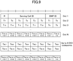
- Fig. 9 illustrates a specification change example (5) related to an operation example in an embodiment of the present invention.
- the mapping by the MAC CE between DCI codepoint and TCI state included in the list in step S2 illustrated in Fig. 4 will be described with reference to Fig. 9 .
- Fig. 9 illustrates a figure in which octets including "DCI codepoint" illustrated in Fig. 8 are deleted from Fig. 8 .
- a first T i field set corresponds to a DCI codepoint 000
- a second T i field set corresponds to the DCI codepoint 001
- the T i field sets correspond to the DCI codepoints in the ascending order.
- the T i field set may include 128 or more TCI states, similarly to Fig. 7 .
- the number of "DCI codepoints" may be 8 indicated by 3 bits or may be a large number indicated by more bits.
- the TCI states corresponding to the number of TRPs or panels may be activated for each DCI codepoint. Which TCI state among the activated TCI states corresponds to which TRP or panel may be specified in advance or may be configured separately.
- the user equipment 20 can individually designate the TCI state for each of the PDSCHs transmitted from a plurality of TRPs or panels of the base station device 10 and execute communication to which appropriate QCL assumption is applied.
- the base station device 10 and the user equipment 20 have functions for implementing the embodiments described above. However, each of the base station device 10 and the user equipment 20 may have only some of the functions in the embodiment.
- Fig. 10 is a diagram illustrating an example of a functional configuration of the base station device 10 in an embodiment of the present invention.
- the base station device 10 includes a transmitting unit 110, a receiving unit 120, a setting unit 130, and a control unit 140.
- the functional configuration illustrated in Fig. 10 is only an example.
- a functional classification and names of the functional unit may be any classification and any names as long as the operation according to an embodiment of the present invention can be executed.
- the transmitting unit 110 includes a function of generating a signal to be transmitted to the user equipment 20 side and transmitting the signal wirelessly.
- the receiving unit 120 includes a function of receiving various kinds of signals transmitted from the user equipment 20 and acquiring, for example, higher layer information from received signals. Further, the transmitting unit 110 has a function of transmitting NR-PSS, NR-SSS, NR-PBCH, DL/UL control signals, or the like to the user equipment 20.
- the setting unit 130 stores configuration information configured in advance and various kinds of configuration information to be transmitted to the user equipment 20 in a storage device, and reads out them from the storage device if necessary.
- content of the configuration information is a communication configuration or the like related to the TRP or panel of the user equipment 20.
- control unit 140 performs a process related to the communication configuration related to the TRP or panel of the user equipment 20. As described in the embodiment, the control unit 140 controls communication in which a plurality of TRPs or panels are used.
- the functional unit related to signal transmission in the control unit 140 may be included in the transmitting unit 110, and the functional unit related to signal reception in the control unit 140 may be included in the receiving unit 120.
- Fig. 11 illustrates an example of a functional configuration of the user equipment 20.
- the user equipment 20 includes a transmitting unit 210, a receiving unit 220, a setting unit 230, and a control unit 240.
- the functional configuration illustrated in Fig. 11 is only an example.
- a functional classification and names of the functional unit may be any classification and any names as long as the operation according to an embodiment of the present invention can be executed.
- the transmitting unit 210 generates a transmission signal from transmission data and transmits the transmission signal wirelessly.
- the receiving unit 220 wirelessly receives various kinds of signals and acquires higher layer signals from received physical layer signals.
- the receiving unit 220 includes a function of receiving NR-PSS, NR-SSS, NR-PBCH, and DL/UL/SL control signals or the like transmitted from the base station device 10.
- the transmitting unit 210 transmits a physical sidelink control channel (PSCCH), a physical sidelink shared channel (PSSCH), a physical sidelink discovery channel (PSDCH), a physical sidelink broadcast channel (PSBCH), and the like to other user equipment 20 as D2D communication, and the receiving unit 120 receives PSCCH, PSSCH, PSDCH, PSBCH, and the like from other user equipment 20.
- PSCCH physical sidelink control channel
- PSSCH physical sidelink shared channel
- PSDCH physical sidelink discovery channel
- PSBCH physical sidelink broadcast channel
- the setting unit 230 stores various kinds of configuration information received from the base station device 10 or the user equipment 20 by the receiving unit 220 in a storage device, and reads out them from the storage device if necessary.
- the setting unit 230 also stores configuration information configured in advance.
- content of the configuration information is a communication configuration or the like related to the TRP or panel of the user equipment 20.
- control unit 240 controls communication in which a plurality of TRPs or panels are used on the basis of the communication configuration acquired from the base station device 10.
- the functional unit related to signal transmission in the control unit 240 may be included in the transmitting unit 210, and the functional unit related to signal reception in the control unit 240 may be included in the receiving unit 220.
- each functional block may be implemented by one device which is physically or logically combined or may be implemented by a plurality of devices, that is, two or more devices which are physically and/or logically separated and are directly or indirectly connected (for example, a wired and/or wireless manner).
- the function block may be implemented by combining software with the one device or the plurality of devices.
- the functions include determining, deciding, judging, computing, calculating, processing, deriving, investigating, searching, confirming, receiving, transmitting, outputting, accessing, resolving, selecting, choosing, establishing, comparing, assuming, expectation, regarding, broadcasting, notifying, communicating, forwarding, configuring, reconfiguring, allocating, mapping, assigning, and the like but are not limited thereto.
- a functional block (configuring unit) that causes transmission to function is referred to as a transmitting unit or a transmitter.
- an implementation method is not particularly limited.
- the base station device 10, the user equipment 20, or the like in one embodiment of the present disclosure may function as a computer for processing the present disclosure's wireless communication method.
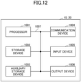
- Fig. 12 is a diagram illustrating an example of a hardware configuration of the base station device 10 and the user equipment 20 according to an embodiment of the present disclosure.
- Each of the base station device 10 and the user equipment 20 may be physically configured as a computer device including a processor 1001, a storage device 1002, an auxiliary storage device 1003, a communication device 1004, an input device 1005, an output device 1006, a bus 1007, and the like.
- each of the base station device 10 and the user equipment 20 may be configured to include one or more devices illustrated in the drawing or may be configured without including some devices.
- Each function in each of the base station device 10 and the user equipment 20 is implemented such that predetermined software (program) is read on hardware such as the processor 1001 and the storage device 1002, and the processor 1001 performs an operation and controls communication by the communication device 1004 and reading and/or writing of data in the storage device 1002 and the auxiliary storage device 1003.
- predetermined software program
- the processor 1001 performs an operation and controls communication by the communication device 1004 and reading and/or writing of data in the storage device 1002 and the auxiliary storage device 1003.
- the processor 1001 operates an operating system and controls the entire computer.
- the processor 1001 may be configured with a central processing unit (CPU) including an interface with a peripheral device, a control device, an operation device, a register, and the like.
- CPU central processing unit
- the control unit 140, the control unit 240, and the like described above may be implemented by the processor 1001.
- the processor 1001 reads a program (program code), a software module, or data from at least one of the auxiliary storage device 1003 and/or the communication device 1004 out to the storage device 1002, and executes various types of processes according to them.
- a program causing a computer to execute at least some of the operations described in the above embodiment is used as the program.
- the control unit 140 of the base station device 10 illustrated in Fig. 10 may be implemented by a control program which is stored in the storage device 1002 and operates on the processor 1001.
- the control unit 240 of the user equipment 20 illustrated in Fig. 11 may be implemented by a control program which is stored in the storage device 1002 and operates on the processor 1001.
- Various types of processes have been described as being performed by one processor 1001 but may be performed simultaneously or sequentially by two or more processors 1001.
- the processor 1001 may be implemented by one or more chips.
- the program may be transmitted from a network via an electric communication line.
- the storage device 1002 is a computer readable recording medium and configured with at least one of a read only memory (ROM), an erasable programmable ROM (EPROM), an electrically erasable programmable ROM (EEPROM), a random access memory (RAM), and the like.
- ROM read only memory
- EPROM erasable programmable ROM
- EEPROM electrically erasable programmable ROM
- RAM random access memory
- the storage device 1002 is also referred to as a "register,” a "cache,” a “main memory,” or the like.
- the storage device 1002 can store programs (program codes), software modules, or the like which are executable for carrying out the communication method according to an embodiment of the present disclosure.
- the auxiliary storage device 1003 is a computer-readable recording medium and may be configured with, for example, at least one of an optical disk such as a compact disc ROM (CD-ROM), a hard disk drive, a flexible disk, a magneto-optical disk (for example, a compact disk, a digital versatile disk, or a Blu-ray (registered trademark) disc, a smart card, a flash memory (for example, a card, a stick, or a key drive), a floppy (registered trademark) disk, a magnetic strip, and the like.
- the storage medium may be, for example, a database, a server, or any other appropriate medium including at least one of the storage device 1002 and the auxiliary storage device 1003.
- the communication device 1004 is hardware (a transceiving device) for performing communication between computers via at least one of a wired network and a wireless network and is also referred to as a "network device,” a “network controller,” a “network card,” a “communication module,” or the like.
- the communication device 1004 may include a high-frequency switch, a duplexer, a filter, a frequency synthesizer, or the like in order to implement at least one of frequency division duplex (FDD) and time division duplex (TDD).
- FDD frequency division duplex
- TDD time division duplex
- a transceiving antenna, an amplifying unit, a transmitting/receiving unit, a transmission line interface, or the like may be implemented by the communication device 1004.
- the transmitting/receiving unit may be implemented by to be physically or logically separated by a transmitting unit and a receiving unit.
- the input device 1005 is an input device (for example, a keyboard, a mouse, a microphone, a switch, a button, a sensor, or the like) that receives an input from the outside.
- the output device 1006 is an output device (for example, a display, a speaker, an LED lamp, or the like) that performs output to the outside.
- the input device 1005 and the output device 1006 may be integrated (for example, a touch panel).
- the respective devices such as the processor 1001 and the storage device 1002 are connected via the bus 1007 to communicate information with each other.
- the bus 1007 may be configured with a single bus or may be configured with different buses between the devices.
- each of the base station device 10 and the user equipment 20 may be configured to include hardware such as a microprocessor, a digital signal processor (DSP), an application specific integrated circuit (ASIC), a programmable logic device (PLD), or a field programmable gate array (FPGA) or all or some of the functional blocks may be implemented by hardware.
- the processor 1001 may be implemented using at least one of these pieces of hardware.
- a user equipment including a control unit that individually applies a configuration related to quasi co-location (QCL) to each of downlink shared channels transmitted from a plurality of transmission reception points (TRPs) or panels on the basis of information related to the transmission configuration state and a communication unit that performs communication via the downlink shared channel to which the configurations related to the plurality of QCLs are individually applied is provided.
- QCL quasi co-location
- the user equipment 20 can individually designate the TCI state for each of the PDSCHs transmitted from a plurality of TRPs or panels of the base station device 10 and execute communication to which appropriate QCL assumption is applied. In other words, it is possible to configure communication in which a plurality of TRPs or panels are used in the wireless communication system.
- the information related to the transmission configuration state may include radio resource control (RRC) signaling, media access control (MAC) signaling, and downlink control information (DCI),
- RRC signaling may include a first number of transmission configuration states
- MAC signaling may activate a second number of transmission configuration states among the first number of transmission configuration states
- DCI may have a field that designates the transmission configuration state of each of the downlink shared channels transmitted from the plurality of TRPs or panels from the second number of activated transmission configuration states.
- the user equipment 20 can individually designate the TCI state for each of the PDSCHs transmitted from multiple TRPs or panels of the base station device 10.
- the MAC signaling may indicate which of the second number of activated transmission configurations is applied to each of the downlink shared channels transmitted from the plurality of TRPs or panels for each codepoint of a field of the DCI.
- the user equipment 20 can individually designate the TCI state for each of the PDSCHs transmitted from multiple TRPs or panels of the base station device 10.
- the MAC signaling may indicate which of the first number of transmission configurations is applied to each of the downlink shared channels transmitted from the plurality of TRPs or panels for each codepoint of a field of the DCI.
- the user equipment 20 can individually designate the TCI state for each of the PDSCHs transmitted from multiple TRPs or panels of the base station device 10.
- the MAC signaling may not explicitly include information indicating the codepoint of the field of the DCI.
- the user equipment 20 can individually designate the TCI state for each of the PDSCHs transmitted from multiple TRPs or panels of the base station device 10 with a smaller payload.
- a base station device including a transmitting unit that transmits information related to a transmission configuration state of a downlink shared channel to a user equipment, a control unit that individually applies a configuration related to quasi co-location (QCL) to each of the downlink shared channels transmitted from a plurality of transmission reception points (TRPs) or panels on the basis of the information related to the transmission configuration state, and a communication unit that performs communication via the downlink shared channel to which the configurations related to the plurality of QCLs are individually applied is provided.
- a transmitting unit that transmits information related to a transmission configuration state of a downlink shared channel to a user equipment
- a control unit that individually applies a configuration related to quasi co-location (QCL) to each of the downlink shared channels transmitted from a plurality of transmission reception points (TRPs) or panels on the basis of the information related to the transmission configuration state
- TRPs transmission reception points
- the user equipment 20 can individually designate the TCI state for each of the PDSCHs transmitted from a plurality of TRPs or panels of the base station device 10 and execute communication to which appropriate QCL assumption is applied. In other words, it is possible to configure communication in which a plurality of TRPs or panels are used in the wireless communication system.
- Operations of a plurality of functional units may be performed physically by one component, or an operation of one functional unit may be physically performed by a plurality of parts.
- the order of the processes may be changed as long as there is no inconsistency.
- the base station device 10 and the user equipment 20 have been described using the functional block diagrams, but such devices may be implemented by hardware, software, or a combination thereof.
- Software executed by the processor included in the base station device 10 according to the embodiment of the present invention and software executed by the processor included in the user equipment 20 according to the embodiment of the present invention may be stored in a random access memory (RAM), a flash memory, a read only memory (ROM), an EPROM, an EEPROM, a register, a hard disk (HDD), a removable disk, a CD-ROM, a database, a server, or any other appropriate storage medium.
- RAM random access memory
- ROM read only memory
- EPROM an EPROM
- EEPROM electrically erasable programmable read-only memory
- register a register
- HDD hard disk
- CD-ROM compact disc-read only memory
- database a database
- server or any other appropriate storage medium.
- an indication of information is not limited to the aspect or embodiment described in the present disclosure and may be given by any other method.
- the indication of information may be given by physical layer signaling (for example, downlink control information (DCI) or uplink control information (UCI)), upper layer signaling (for example, radio resource control (RRC) signaling, medium access control (MAC) signaling, broadcast information (master information block (MIB), system information block (SIB))), other signals, or a combination thereof.
- RRC signaling may be referred to as an RRC message and may be, for example, an RRC connection setup message, an RRC connection reconfiguration message, or the like.
- Each aspect and embodiment of the present invention may be applied to at least one of Long Term Evolution (LTE), LTE-advanced (LTE-A), SUPER 3G, IMT-advanced, 4th generation mobile communication system (4G), 5th generation mobile communication system (5G), Future Radio Access (FRA), New Radio (NR), W-CDMA (registered trademark), GSM (registered trademark), CDMA 2000, Ultra Mobile Broadband (UMB), IEEE 802.11 (Wi-Fi (registered trademark)), IEEE 802.16 (WiMAX (registered trademark)), IEEE 802.20, Ultra-WideBand (UWB), Bluetooth (registered trademark), a system using any other appropriate system, and next generation systems extended on the basis of these standards. Further, a plurality of systems may be combined and applied (for example, a combination of at least one of LTE and LTE-A and 5G or the like).
- a specific action that is supposed to be performed by the base station device 10 may be performed by an upper node in some cases.
- various operations performed for communication with the user equipment 20 can be obviously performed by at least one of the base station and any network node (for example, an MME, an S-GW, or the like is considered, but it is not limited thereto) other than the base station device 10 and/or the base station device 10.
- any network node for example, an MME, an S-GW, or the like is considered, but it is not limited thereto
- the example in which the number of network nodes excluding the base station device 10 is one has been described above, but other network nodes in which a plurality of other network nodes (for example, an MME and an S-GW) are combined may be provided.
- Information, a signal, or the like described in the present disclosure may be output from an upper layer (or a lower layer) to a lower layer (or an upper layer).
- Information, a signal, or the like described in the present disclosure may be input and output via a plurality of network nodes.
- Input and output information and the like may be stored in a specific place (for example, a memory) or may be managed through a management table. Input and output information and the like may be overwritten, updated, or additionally written. Output information and the like may be deleted. Input information and the like may be transmitted to another device.
- the determination of the present disclosure may be performed in accordance with a value (0 or 1) indicated by one bit, may be performed in accordance with a Boolean value (true or false), or may be performed by a comparison of numerical values (for example, a comparison with a predetermined value).
- Software can be interpreted widely to mean a command, a command set, a code, a code segment, a program code, a program, a subprogram, a software module, an application, a software application, a software package, a routine, a subroutine, an object, an executable file, an execution thread, a procedure, a function, and the like regardless of whether software is called software, firmware, middleware, a microcode, a hardware description language, or any other name.
- software, commands, information, and the like may be transmitted and received via a transmission medium.
- a transmission medium such as a coaxial cable, a fiber optic cable, a twisted pair, or a digital subscriber line (DSL)
- a radio technology such as infrared rays or a microwave
- Information, signals, and the like described in this specification may be indicated using any one of a variety of different techniques.
- data, instructions, commands, information, signals, bits, symbols, chips, and the like which are mentioned throughout the above description may be indicated by voltages, currents, electromagnetic waves, magnetic particles, optical fields or photons, or an arbitrary combination thereof.
- a channel and a symbol may be a signal.
- a signal may be a message.
- a component carrier (CC) may be referred to as a "carrier frequency,” a "cell,” or the like.
- system and “network” used in the present disclosure are used interchangeably.
- radio resources may be those indicated by an index.
- base station BS
- radio base station base station device
- fixed station Node B
- eNode B eNode B
- gNodeB gNodeB
- the base station eNB can accommodate one or more (for example, three) cells.
- the entire coverage area of the base station can be partitioned into a plurality of small areas, and each small area can provide a communication service through a base station subsystem (for example, a small indoor base station (a remote radio head (RRH)).
- a base station subsystem for example, a small indoor base station (a remote radio head (RRH)
- RRH remote radio head
- cell or “sector” refers to the whole or a part of the coverage area of at least one of the base station and the base station subsystem that performs a communication service in the coverage.
- MS mobile station
- UE user equipment
- terminal terminal
- the mobile station may be a subscriber station, a mobile unit, a subscriber unit, a wireless unit, a remote unit, a mobile device, a wireless device, a wireless communication device, a remote device, a mobile subscriber station, an access terminal, a mobile terminal, a wireless terminal, a remote terminal, handset, user agent, mobile client, client, or may be referred to by some other suitable term.
- At least one of the base station and the mobile station may be also referred to as a transmitting device, a receiving device, a communication device, or the like.
- At least one of the base station and the mobile station may be a device installed in a mobile body, a mobile body itself, or the like.
- the moving body may be a vehicle (for example, a car, an airplane, or the like), a moving body that moves unmanned (for example, a drone, an autonomous car or the like), or a robot (manned type or unmanned type).
- At least one of the base station and the mobile station includes a device which need not necessarily move during a communication operation.
- at least one of the base station and the mobile station may be an Internet of things (IoT) device such as a sensor.
- IoT Internet of things
- the base station in the present disclosure may be replaced with a user terminal.
- each aspect/embodiment of the present disclosure may be applied to a configuration in which communication between the base station and the user terminal is replaced with communication between a plurality of user equipment 20 (for example, which may be referred to as device-to-device (D2D) or vehicle-to-everything (V2X)).
- the user equipment 20 may have the functions of the base station device 10 described above.
- the terms "uplink” and "downlink” may be replaced with terms (for example, "side") corresponding to inter-terminal communication.
- an uplink channel, a downlink channel, or the like may be read as side channels.
- the user terminal in the present disclosure may be replaced with the base station.
- the base station may have the functions of the above-mentioned user terminal.
- determining and “deciding” used in this specification may include a wide variety of actions.
- “determining” and “deciding” may include, for example, events in which events such as judging, calculating, computing, processing, deriving, investigating, looking up, search, and inquiry (for example, looking up in a table, a database, or another data structure), or ascertaining are regarded as “determining” or “deciding.”
- “determining” and “deciding” may include, for example, events in which events such as receiving (for example, receiving information), transmitting (for example, transmitting information), input, output, or accessing (for example, accessing data in a memory) are regarded as “determining” or “deciding.”
- “determining” and “deciding” may include, for example, events in which events such as resolving, selecting, choosing, establishing, or comparing are regarded as “determining” or “deciding.”
- “determining” and “deciding” may include events in which a certain operation is regarded as “determining” or “deciding.”
- "determining (deciding) may include events in
- connection means any direct or indirect connection or coupling between two or more elements and may include the presence of one or more intermediate elements between two elements which are “connected” or “coupled.”
- the coupling or the connection between the elements may be physical, logical, or a combination thereof.
- connection may be replaced with "access.”
- two elements may be considered to be “connected” or “coupled” with each other using at least one of one or more electric wires, cables and/or a printed electrical connection or using electromagnetic energy having a wavelength in a radio frequency domain, a microwave region, or a light (both visible and invisible) region as non-limiting and non-exhaustive examples.
- a reference signal may be abbreviated as RS and may be referred to as a pilot, depending on a standard to be applied.
- phrase “on the basis of” used in the present disclosure is not limited to “on the basis of only” unless otherwise stated. In other words, a phrase “on the basis of” means both “on the basis of only” and “on the basis of at least.”
- any reference to an element using a designation such as "first,” “second,” or the like used in the present disclosure does not generally restrict quantities or an order of those elements. Such designations can be used in the present disclosure as a convenient method of distinguishing two or more elements. Thus, reference to the first and second elements does not mean that only two elements can be adopted there, or the first element must precede the second element in a certain form.
- a radio frame may include one or more frames in the time domain.
- each of one or more frames may be referred to as a subframe.
- the subframe may further include one or more slots in the time domain.
- the subframe may have a fixed time length (for example, 1 ms) not depending on numerology.
- the numerology may be a communication parameter applied to at least one of transmission and reception of a certain signal or channel.
- the numerology may indicate at least one of a subcarrier spacing (SCS), a bandwidth, a symbol length, a cyclic prefix length, a transmission time interval (TTI), a number of symbols per TTI, a radio frame configuration, a specific filtering process performed in the frequency domain by a transceiver, a specific windowing process performed in the time domain by a transceiver, and the like.
- SCS subcarrier spacing
- TTI transmission time interval
- the slot may include one or more symbols (orthogonal frequency division multiplexing (OFDM) symbols, single carrier frequency division multiple access (SC-FDMA) symbols, or the like) in the time domain.
- the slot may be a time unit based on the numerology.
- the slot may include a plurality of mini slots. Each mini slot may include one or more symbols in the time domain. Further, the mini slot may be referred to as a sub-slot. The mini slot may include fewer symbols than a slot.
- a PDSCH (or PUSCH) transmitted in units of times greater than the mini slot may be referred to as a PDSCH (or PUSCH) mapping type A.
- a PDSCH (or PUSCH) transmitted using a mini slot may be referred to as a PDSCH (or PUSCH) mapping type B.
- All of a radio frame, a subframe, a slot, a mini slot, and a symbol indicates a time unit for transmitting a signal.
- a radio frame, a subframe, a slot, a mini slot, and a symbol different designations respectively corresponding to them may be used.
- one subframe may be referred to as a transmission time interval (TTI: Transmission Time Interval), or a plurality of consecutive subframes may be referred to as TTIs, or one slot or one mini slot may be referred to as a TTI.
- TTI Transmission Time Interval
- at least one of the subframe and the TTI may be a subframe (1 ms) in the existing LTE, may be a period shorter than 1 ms (for example, 1 to 13 symbols), or may be referred to as a period longer than 1 ms.
- a unit representing the TTI may be referred to as slot, a mini slot, or the like instead of the subframe.
- the TTI refers to a minimum time unit of scheduling in wireless communication.
- the base station performs scheduling of allocating a radio resource (a frequency bandwidth, a transmission power, or the like which can be used in each user equipment 20) to each user equipment 20 in units of TTIs.
- a radio resource a frequency bandwidth, a transmission power, or the like which can be used in each user equipment 20
- the definition of the TTI is not limited thereto.
- the TTI may be a transmission time unit such as a channel coded data packet (transport block), a code block, or a code word, or may be a processing unit such as scheduling or link adaptation. Further, when a TTI is given, a time interval (for example, the number of symbols) in which a transport block, a code block, a code word, or the like is actually mapped may be shorter than the TTI.
- one or more TTIs may be a minimum time unit of scheduling. Further, the number of slots (the number of mini slots) constituting the minimum time unit of scheduling may be controlled.
- a TTI having a time length of 1 ms may be referred to as a common TTI (TTI in LTE Rel. 8 to 12), a normal TTI, a long TTI, a common subframe, a normal subframe, a long subframe, a slot, or the like.
- a TTI shorter than the common TTI may be referred to as a reduced TTI, a short TTI, a partial TTI (a partial or fractional TTI), a reduced subframe, a short subframe, a mini slot, a sub slot, a slot, or the like.
- a long TTI for example, a common TTI, a subframe, or the like
- a short TTI for example, a reduced TTI or the like
- a TTI having a TTI length which is less than a TTI length of a long TTI and equal to or more than 1 ms.
- the resource block (RB) is a resource allocation unit in the time domain and the frequency domain and may include one or more consecutive subcarriers in the frequency domain.
- the number of subcarriers included in an RB may be the same irrespective of a numerology and may be, for example, 12.
- the number of subcarriers included in an RB may be decided on the basis of a numerology.
- a time domain of an RB may include one or more symbols and may be a length of one slot, one mini slot, one subframe, or one TTI.
- Each of one TTI, one subframe, or the like may be constituted by one or more resource blocks.
- one or more RBs may be referred to as a physical resource block (PRB), a subcarrier group (SCG), a resource element group (REG), a PRB pair, an RB pair, or the like.
- PRB physical resource block
- SCG subcarrier group
- REG resource element group
- the resource block may be constituted by one or more resource elements (RE).
- RE resource elements
- one RE may be a radio resource region of one subcarrier and one symbol.
- a bandwidth part (which may be referred to as a partial bandwidth) may indicate a subset of consecutive common resource blocks (RBs) for a certain numerology in a certain carrier.
- a common RB may be specified by an index of an RB based on a common reference point of a carrier.
- a PRB may be defined in a BWP and numbered in a BWP.
- the BWP may include a BWP for UL (UL BWP) and a BWP for DL (DL BWP).
- UL BWP UL BWP
- DL BWP DL BWP
- one or more BWPs may be configured within one carrier.
- At least one of configured BWPs may be active, and it may not be assumed that the UE transmits and receives a predetermined signal/channel outside an active BWP. Further, a "cell,” a “carrier,” or the like in the present disclosure may be replaced with a "BWP.”
- Structures of the radio frame, the subframe, slot, the mini slot, and the symbol are merely examples.
- configurations such as the number of subframes included in a radio frame, the number of slots per subframe or radio frame, the number of mini slots included in a slot, the number of symbols and RBs included in a slot or a mini slot, the number of subcarriers included in an RB, the number of symbols in a TTI, a symbol length, a cyclic prefix (CP) length, and the like can be variously changed.
- CP cyclic prefix
- the present disclosure may include a case in which a noun following the article is plural.
- the wording "A and B are different” may mean “A and B are different from each other.” Further, the wording may mean “each of A and B is different from C.” Terms such as “separated,” “coupled,” or the like may also be interpreted similarly to “different.”
- an indication of predetermined information (for example, indication of "being X") is not limited to being performed explicitly, but may be performed implicitly (for example, not indicating the predetermined information).
- the transmitting unit 210 and the receiving unit 220 are examples of communication units.
- the transmitting unit 110 and the receiving unit 120 are examples of communication units.
- the TCI state is an example of a transmission configuration state.
- the PDSCH is an example of a downlink shared channel.
Landscapes
- Engineering & Computer Science (AREA)
- Signal Processing (AREA)
- Computer Networks & Wireless Communication (AREA)
- Mobile Radio Communication Systems (AREA)
Applications Claiming Priority (1)
| Application Number | Priority Date | Filing Date | Title |
|---|---|---|---|
| PCT/JP2019/013469 WO2020194638A1 (ja) | 2019-03-27 | 2019-03-27 | ユーザ装置及び基地局装置 |
Publications (1)
| Publication Number | Publication Date |
|---|---|
| EP3952505A1 true EP3952505A1 (de) | 2022-02-09 |
Family
ID=72611187
Family Applications (1)
| Application Number | Title | Priority Date | Filing Date |
|---|---|---|---|
| EP19921568.2A Withdrawn EP3952505A1 (de) | 2019-03-27 | 2019-03-27 | Benutzervorrichtung und basisstationsvorrichtung |
Country Status (6)
| Country | Link |
|---|---|
| US (1) | US12016035B2 (de) |
| EP (1) | EP3952505A1 (de) |
| JP (1) | JP7170842B2 (de) |
| KR (1) | KR20210138011A (de) |
| CN (1) | CN113678530A (de) |
| WO (1) | WO2020194638A1 (de) |
Families Citing this family (9)
| Publication number | Priority date | Publication date | Assignee | Title |
|---|---|---|---|---|
| CN111277387B (zh) * | 2019-04-26 | 2021-05-07 | 维沃移动通信有限公司 | 指示信息的传输方法及通信设备 |
| EP3780839A1 (de) * | 2019-08-14 | 2021-02-17 | Panasonic Intellectual Property Corporation of America | Benutzergerät und planungsknoten |
| CN114223226B (zh) * | 2019-08-23 | 2024-08-27 | 联想(北京)有限公司 | Tci状态配置和激活或去激活的装置和方法 |
| WO2021087824A1 (zh) * | 2019-11-06 | 2021-05-14 | 北京小米移动软件有限公司 | 数据传输方法、装置及存储介质 |
| EP4055944B1 (de) * | 2019-11-08 | 2025-02-26 | Telefonaktiebolaget LM Ericsson (publ) | Aktualisierung des aktiven tci-status für einzel-pdcch-basierten multi-trp-pdsch oder multi-pdcch-basierten multi-trp-pdsch |
| IL297141A (en) * | 2020-04-09 | 2022-12-01 | Ericsson Telefon Ab L M | Systems and methods for activating tci mode and mapping a code point to tci mode |
| WO2021244413A1 (en) * | 2020-06-02 | 2021-12-09 | Shanghai Langbo Communication Technology Company Limited | Method and device in a node used for wireless communication |
| US12593339B2 (en) * | 2021-01-18 | 2026-03-31 | Telefonaktiebolaget Lm Ericsson (Publ) | Dynamic indication of physical uplink shared channel (PUSCH) transmission to a single transmission reception point (TRP) or multiple TRPs |
| CN118056369A (zh) * | 2021-09-30 | 2024-05-17 | Oppo广东移动通信有限公司 | 多个物理下行共享信道pdsch的无线通信装置及方法 |
Family Cites Families (5)
| Publication number | Priority date | Publication date | Assignee | Title |
|---|---|---|---|---|
| TW201907680A (zh) * | 2017-06-14 | 2019-02-16 | 美商Idac控股公司 | 無線網路中統一波束管理 |
| KR102573235B1 (ko) * | 2017-08-11 | 2023-09-01 | 한국전자통신연구원 | 하향링크 제어 채널의 송수신 방법 및 이를 이용하는 장치 |
| ES2982027T3 (es) * | 2018-07-25 | 2024-10-14 | Beijing Xiaomi Mobile Software Co Ltd | Procedimiento y dispositivo de configuración de transmisión |
| US11765023B2 (en) * | 2018-07-27 | 2023-09-19 | Beijing Xiaomi Mobile Software Co., Ltd. | Configuration method and apparatus for transmission configuration indication |
| US12150151B2 (en) * | 2019-02-15 | 2024-11-19 | Qualcomm Incorporated | Methods and apparatus for PDSCH TCI states activation-deactivation in multi-TRP |
-
2019
- 2019-03-27 EP EP19921568.2A patent/EP3952505A1/de not_active Withdrawn
- 2019-03-27 KR KR1020217027645A patent/KR20210138011A/ko not_active Ceased
- 2019-03-27 CN CN201980094390.4A patent/CN113678530A/zh active Pending
- 2019-03-27 US US17/441,172 patent/US12016035B2/en active Active
- 2019-03-27 WO PCT/JP2019/013469 patent/WO2020194638A1/ja not_active Ceased
- 2019-03-27 JP JP2021508579A patent/JP7170842B2/ja active Active
Also Published As
| Publication number | Publication date |
|---|---|
| US12016035B2 (en) | 2024-06-18 |
| JPWO2020194638A1 (de) | 2020-10-01 |
| CN113678530A (zh) | 2021-11-19 |
| WO2020194638A1 (ja) | 2020-10-01 |
| US20220167322A1 (en) | 2022-05-26 |
| JP7170842B2 (ja) | 2022-11-14 |
| KR20210138011A (ko) | 2021-11-18 |
Similar Documents
| Publication | Publication Date | Title |
|---|---|---|
| US12016035B2 (en) | User equipment and base station device | |
| US12457613B2 (en) | Terminal, base station, and communication method to support scheduling of cells with single control information | |
| US20240057031A1 (en) | Terminal, base station, and transmission method | |
| JP7073529B2 (ja) | 端末、基地局及び通信方法 | |
| WO2021199415A1 (ja) | 端末及び通信方法 | |
| WO2021140674A1 (ja) | 端末及び通信方法 | |
| WO2021140677A1 (ja) | 端末及び通信方法 | |
| EP3952468A1 (de) | Benutzergerät | |
| JPWO2020157873A1 (ja) | ユーザ装置及び基地局装置 | |
| WO2022079781A1 (ja) | 端末、基地局及び通信方法 | |
| US20220182978A1 (en) | User equipment and base station device | |
| EP3883306A1 (de) | Benutzervorrichtung und basisstationsvorrichtung | |
| WO2021149246A1 (ja) | 端末、基地局及び通信方法 | |
| WO2022049733A1 (ja) | 端末、基地局及び通信方法 | |
| WO2022044141A1 (ja) | 端末、基地局及び通信方法 | |
| WO2020246185A1 (ja) | 端末及び基地局 | |
| EP3930393A1 (de) | Benutzervorrichtung und basisstationsvorrichtung | |
| WO2021140676A1 (ja) | 端末及び通信方法 | |
| WO2021149110A1 (ja) | 端末及び通信方法 | |
| JPWO2020157874A1 (ja) | ユーザ装置及び基地局装置 | |
| US12439274B2 (en) | User equipment, base station apparatus and communication method | |
| EP4142332A1 (de) | Endgerät und kommunikationsverfahren | |
| WO2022149223A1 (ja) | 端末、基地局及び通信方法 | |
| WO2022079780A1 (ja) | 端末、基地局及び通信方法 | |
| WO2020230623A1 (ja) | ユーザ装置及び基地局装置 |
Legal Events
| Date | Code | Title | Description |
|---|---|---|---|
| STAA | Information on the status of an ep patent application or granted ep patent |
Free format text: STATUS: THE INTERNATIONAL PUBLICATION HAS BEEN MADE |
|
| PUAI | Public reference made under article 153(3) epc to a published international application that has entered the european phase |
Free format text: ORIGINAL CODE: 0009012 |
|
| STAA | Information on the status of an ep patent application or granted ep patent |
Free format text: STATUS: REQUEST FOR EXAMINATION WAS MADE |
|
| 17P | Request for examination filed |
Effective date: 20210920 |
|
| AK | Designated contracting states |
Kind code of ref document: A1 Designated state(s): AL AT BE BG CH CY CZ DE DK EE ES FI FR GB GR HR HU IE IS IT LI LT LU LV MC MK MT NL NO PL PT RO RS SE SI SK SM TR |
|
| DAV | Request for validation of the european patent (deleted) | ||
| DAX | Request for extension of the european patent (deleted) | ||
| STAA | Information on the status of an ep patent application or granted ep patent |
Free format text: STATUS: THE APPLICATION HAS BEEN WITHDRAWN |
|
| 18W | Application withdrawn |
Effective date: 20220809 |