EP3952629B1 - Utensil for agricultural working - Google Patents
Utensil for agricultural working Download PDFInfo
- Publication number
- EP3952629B1 EP3952629B1 EP20719507.4A EP20719507A EP3952629B1 EP 3952629 B1 EP3952629 B1 EP 3952629B1 EP 20719507 A EP20719507 A EP 20719507A EP 3952629 B1 EP3952629 B1 EP 3952629B1
- Authority
- EP
- European Patent Office
- Prior art keywords
- fastening device
- utensil
- support element
- work tool
- central body
- Prior art date
- Legal status (The legal status is an assumption and is not a legal conclusion. Google has not performed a legal analysis and makes no representation as to the accuracy of the status listed.)
- Active
Links
Images



Classifications
-
- A—HUMAN NECESSITIES
- A01—AGRICULTURE; FORESTRY; ANIMAL HUSBANDRY; HUNTING; TRAPPING; FISHING
- A01B—SOIL WORKING IN AGRICULTURE OR FORESTRY; PARTS, DETAILS, OR ACCESSORIES OF AGRICULTURAL MACHINES OR IMPLEMENTS, IN GENERAL
- A01B59/00—Devices specially adapted for connection between animals or tractors and agricultural machines or implements
- A01B59/04—Devices specially adapted for connection between animals or tractors and agricultural machines or implements for machines pulled or pushed by a tractor
-
- A—HUMAN NECESSITIES
- A01—AGRICULTURE; FORESTRY; ANIMAL HUSBANDRY; HUNTING; TRAPPING; FISHING
- A01B—SOIL WORKING IN AGRICULTURE OR FORESTRY; PARTS, DETAILS, OR ACCESSORIES OF AGRICULTURAL MACHINES OR IMPLEMENTS, IN GENERAL
- A01B23/00—Elements, tools, or details of harrows
- A01B23/02—Teeth; Fixing the teeth
-
- A—HUMAN NECESSITIES
- A01—AGRICULTURE; FORESTRY; ANIMAL HUSBANDRY; HUNTING; TRAPPING; FISHING
- A01B—SOIL WORKING IN AGRICULTURE OR FORESTRY; PARTS, DETAILS, OR ACCESSORIES OF AGRICULTURAL MACHINES OR IMPLEMENTS, IN GENERAL
- A01B35/00—Other machines for working soil
- A01B35/20—Tools; Details
- A01B35/22—Non-rotating tools; Resilient or flexible mounting of rigid tools
- A01B35/225—Non-rotating tools; Resilient or flexible mounting of rigid tools the tools being adapted to allow the chisel point to be easily fitted or removed from the shank
-
- A—HUMAN NECESSITIES
- A01—AGRICULTURE; FORESTRY; ANIMAL HUSBANDRY; HUNTING; TRAPPING; FISHING
- A01B—SOIL WORKING IN AGRICULTURE OR FORESTRY; PARTS, DETAILS, OR ACCESSORIES OF AGRICULTURAL MACHINES OR IMPLEMENTS, IN GENERAL
- A01B39/00—Machines specially adapted for working soil on which crops are growing
- A01B39/20—Tools; Details
- A01B39/22—Tools; Mounting tools
Definitions
- the present invention falls within the scope of farming tools and utensils and equipment for working the soil.
- the invention in particular refers to farming utensils comprising a tool for working the soil and a support element which can be fastened to a farm vehicle, where such support element can be disconnected from the vehicle itself.
- cultivators It is common practice in agriculture to use farming apparatuses generically defined as cultivators; such class of tools includes among others, ploughs, spiked harrows, subsoil ploughs, etc.
- Such tools comprise a plurality of work elements fastened to a support frame of the movable farm vehicle, for example a tractor, and prepared to perform the soil working procedures such as ploughing the subsoil, ploughing, cultivating, minimum tillage, etc.
- the frame of said tools can be fastened to and directly supported by the tractor or can be dragged thereby, for example by means of wheels.
- the working tools can have various shapes and sizes based on the tasks to be performed, and they are fastened to support elements generally having an elongated and/or curved shape, called spring-loaded tines, which in turn are connected to the support frame.
- a farming apparatus or cultivator, comprises a support frame provided with a plurality of aligned or offset spring-loaded tines, each fastened to a work tool.
- the work tools can also be disassembled to be replaced with new tools due to wear or damage, or with different tools when the farmer requires performing different operations on different soil.
- the work tools are reversibly fastened to a connecting end of the support element, for example by means of screws or bolts.
- the fastening means can become locked, making the release operation longer and more difficult, especially if the cultivator comprises several spring-loaded tines, each with the respective work tool.
- the farmer in any case is to arrange adequate means for removing the fastening devices of the work tools; moreover, if bolts or the like are involved, the same can be lost too easily once they are removed.
- farming work devices were conceived comprising an adaptor fastened by means of bolts to a free end of the support element and configured to be engaged by a leg or stem of the agricultural working machine.
- the tool can be assembled on the adaptor and locked in working position.
- specific locking means which mutually fasten the tool and the adaptor are provided.
- the aforesaid devices allow simplifying and accelerating the assembly/disassembly procedures of the tools to/from the spring-loaded tines, but they too have certain drawbacks. Indeed, the locking means can remain locked due to scale, rust, dirt, soil, etc. and prevent the tool from being released from the adaptor. In the same way, the leg can remain wedged and locked to the adaptor.
- the aims of the invention include:
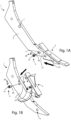
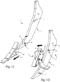
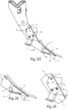
- FIGS. 1A to 2F they illustrate a utensil for farm machines 1 for working the soil which can be associated with a movable farm machine (not shown) and comprising a work tool 2 arranged to interact with the soil and a support element 3 which can be fastened to the farm machine and supported by the work tool 2.
- the embodiment described and illustrated in the accompanying drawings in particular indicates a subsoiler, or scarifier, adapted to break up the more or less deep layers of the soil; however, the device the object of the present invention can advantageously be used for fastening different utensils such as, for example, a hoe, harrow, or any other farm tool adapted to work or interact with the soil.
- the work tool 2 advantageously comprises a working area 21, or operating portion, which is adapted to interact with the soil, and a connecting portion 22, or shaped area, for the removable connection with the support element 3.
- the support element 3 is made in a single piece and comprises holes, or openings 5, adapted to connect the work tool 2 to the support element 3, and therefore to the farm machine, by means of the insertion of a fastening device 4.
- the work tool 2 and the support element 3 advantageously can be coupled to each other by means of the respective shaped areas 22 and 32, which are complementary to each other, as detailed in figures 1A to 2F .
- the feature of the fastening device 4 is that, both in the assembled configuration and in the disassembled one, it always remains inserted in the opening 5 and it is capable of moving from an engaged position to a non-engaged one by means of simply sliding in the opening 5.
- the sliding is obtained by the farmer who acts only on the fastening device 4 by means of suitable tools, such as for example hammers or mallets.
- the fastening device 4 therefore always remains accommodated in the opening 5 and is built in such a manner that one of the two ends thereof, the stem 40 or the head 41, advantageously projects from the opening 5 according to whether or not the work tool 2 is to be released or locked, respectively, from/onto the support element 3.
- the work tool 2 advantageously is made with abutment surfaces 60 and 61 which can therefore allow the positioning or removal thereof, respectively, to/from the support element 3, or the locking thereon.
- Said abutment surfaces 60 and 61 have differences: surface 60 advantageously can be slot-shaped or simply have a profile which serves as abutment for the device 4 to allow the insertion and the removal of the tool 2 by sliding on the support element 3, also when the stem 40 projects from the opening 5 and is in the released position; surface 61 instead is designed so as to allow the sliding of tool 2 only when the head 41 of the fastening device 4 does not project from opening 5, and therefore when the same device 4 is in the released position.
- the surfaces 60 and 61 obtained on the opposite sides of the work tool 2, make it possible for said fastening device 4 to pass from a locked position, according to which said head 41 abuts on surface 61, to a released position, according to which said stem 40 abuts on the second surface 60, and vice versa.
- Figure 4 details the construction components of the fastening device 4.
- said device 4 can be a pin made for example, of steel, having a central body 42 with a greater diameter with respect to the ends, which consist of the stem 40 and the head 41; this is so that said pin advantageously can be coupled under a condition of clearance, albeit minimum, with the opening 5.
- such stem 40 - the profile of which is shown with a dashed line in figure 4 - might also not be present: in order for the device to operate, indeed it is sufficient for the central body 42 to abut with the abutment surface 40 of the work tool 2, and the operation thereof is the one of facilitating the execution of the manual operation in the passage from the engaged and unengaged positions.
- the surface of the central body 42 also has a groove 43 at a given length, adapted to house a braking element 50, which advantageously is made of steel or elastic steel or of an elastomeric material, and preferably is ring- or C- shaped, which interacts by interference with the walls of the opening 5 and ensures the solidity of the coupling.
- a braking element 50 which advantageously is made of steel or elastic steel or of an elastomeric material, and preferably is ring- or C- shaped, which interacts by interference with the walls of the opening 5 and ensures the solidity of the coupling.
- the work tool 2 is shown in the act of being positioned on the support element 3 ( figure 3A ) to better comprehend the operation of the fastening device 4; the fastening device 4 is in the released configuration and the head 41 thereof does not protrude from the opening 5, it being in its own seat.
- the stem 40 which when present comes out of the opening 5 on the other face of the support element 3, can engage the surface 60 of the tool 2 up to the correct positioning thereof on the support element 3.
- the operator can lock the work tool 2 by simply acting on the central body 42, or on the stem 40 when present, of the fastening device 4, thus moving it into the locked position ( figure 3B ) by exerting an axial force along the direction indicated by the arrow F such as to cause the sliding of the fastening device 4 along the opening 5 and the head 41 to occupy the respective seat, at the surface 61, on the work tool 2; in this manner, the head 41 abuts on the surface 61 and the work tool 2 can remain in locked position on the support element 3.
- Figure 5 shows certain embodiments of the surface 60 in order to better illustrate the functionality thereof: it is worth noting that it is sufficient for such surface 60 to have at least one interfering portion, also of minimum size, capable of overlapping the opening 5, at which the central body 42 of the device 4 can abut when the tool 2 is released.
- a coupling system made according to the invention allows the operator to easily and quickly assemble and disassemble the various tools from the supports, regardless of the type of tools.
Landscapes
- Life Sciences & Earth Sciences (AREA)
- Engineering & Computer Science (AREA)
- Mechanical Engineering (AREA)
- Soil Sciences (AREA)
- Environmental Sciences (AREA)
- Zoology (AREA)
- Agricultural Machines (AREA)
- Soil Working Implements (AREA)
- Agricultural Chemicals And Associated Chemicals (AREA)
- Catching Or Destruction (AREA)
Applications Claiming Priority (2)
| Application Number | Priority Date | Filing Date | Title |
|---|---|---|---|
| IT102019000005628A IT201900005628A1 (it) | 2019-04-11 | 2019-04-11 | Utensile per lavorazioni agricole |
| PCT/IT2020/050089 WO2020208664A1 (en) | 2019-04-11 | 2020-04-06 | Utensil for agricultural working |
Publications (3)
| Publication Number | Publication Date |
|---|---|
| EP3952629A1 EP3952629A1 (en) | 2022-02-16 |
| EP3952629C0 EP3952629C0 (en) | 2023-06-07 |
| EP3952629B1 true EP3952629B1 (en) | 2023-06-07 |
Family
ID=67262931
Family Applications (1)
| Application Number | Title | Priority Date | Filing Date |
|---|---|---|---|
| EP20719507.4A Active EP3952629B1 (en) | 2019-04-11 | 2020-04-06 | Utensil for agricultural working |
Country Status (6)
| Country | Link |
|---|---|
| US (1) | US20220159892A1 (it) |
| EP (1) | EP3952629B1 (it) |
| CN (1) | CN113677188B (it) |
| ES (1) | ES2948891T3 (it) |
| IT (1) | IT201900005628A1 (it) |
| WO (1) | WO2020208664A1 (it) |
Families Citing this family (1)
| Publication number | Priority date | Publication date | Assignee | Title |
|---|---|---|---|---|
| IT202100030224A1 (it) * | 2021-11-30 | 2023-05-30 | Torrico S R L | Utensile per lavorazioni agricole |
Family Cites Families (20)
| Publication number | Priority date | Publication date | Assignee | Title |
|---|---|---|---|---|
| US317780A (en) * | 1885-05-12 | Feancis m | ||
| US1141732A (en) * | 1914-11-12 | 1915-06-01 | Caughey C Vance | Cultivator-foot. |
| US3773114A (en) * | 1972-03-31 | 1973-11-20 | R Griffin | Shovel coupling |
| CA1059556A (en) * | 1976-05-04 | 1979-07-31 | Esco Corporation | Locking device for earth moving tool |
| US4195697A (en) * | 1978-02-10 | 1980-04-01 | Griffin Robert M | Shovel coupling with angle of attack adjustment |
| US5009017A (en) * | 1987-01-20 | 1991-04-23 | Caterpillar Inc. | Retaining pin having a positive keeper means |
| GB2209651A (en) * | 1987-09-16 | 1989-05-24 | Philip Harding | Sub-soiling apparatus |
| US5205057A (en) * | 1991-09-10 | 1993-04-27 | Caterpillar Inc. | Retaining mechanism for a tooth assembly |
| US5605196A (en) * | 1995-03-30 | 1997-02-25 | Case Corporation | Multi-piece subsoiler unit for an agricultural implement |
| CA2284457C (en) * | 1999-10-04 | 2002-12-03 | F.P. Bourgault Tillage Tools Ltd. | Quick change sweep retainer |
| US7493964B2 (en) * | 2004-09-08 | 2009-02-24 | Cnh Canada, Ltd. | Ground engaging tool alignment assembly |
| FR2884841B1 (fr) * | 2005-04-26 | 2008-12-05 | Predac Sarl | Procede et dispositif de liaison entre une piece d'usure et son support mis en jeu sur les equipements de manutention de materiaux par les engins de travaux publics |
| US7766093B2 (en) * | 2006-08-29 | 2010-08-03 | Deere & Company | Hydraulic lift rolling basket structure for a tillage implement |
| CN101766068B (zh) * | 2009-07-16 | 2012-07-04 | 上海世达尔现代农机有限公司 | 一种牵引臂的弯转装置 |
| US8770311B2 (en) * | 2011-09-30 | 2014-07-08 | Caterpillar Inc. | Ripper shank assembly |
| US20140209335A1 (en) * | 2013-01-29 | 2014-07-31 | Deere & Company | Drawbar apparatus of an agricultural implement |
| CA2862994C (en) * | 2013-11-06 | 2016-07-26 | Dutch Blacksmith Shop Ltd. | Pin adapter bushing for retaining a furrowing tip on a shank body |
| US9493926B2 (en) * | 2015-02-02 | 2016-11-15 | Caterpillar Inc. | Pin assembly for work implement coupling assembly having float and lock positions |
| US10645853B2 (en) * | 2017-04-11 | 2020-05-12 | Cnh Industrial America Llc | Shank assembly for an agricultural implement with improved tillage point retention and related methods |
| CN108848703A (zh) * | 2018-07-24 | 2018-11-23 | 中国农业科学院草原研究所 | 一种缓冲式深松犁及切根松土装置 |
-
2019
- 2019-04-11 IT IT102019000005628A patent/IT201900005628A1/it unknown
-
2020
- 2020-04-06 US US17/594,291 patent/US20220159892A1/en not_active Abandoned
- 2020-04-06 EP EP20719507.4A patent/EP3952629B1/en active Active
- 2020-04-06 WO PCT/IT2020/050089 patent/WO2020208664A1/en not_active Ceased
- 2020-04-06 ES ES20719507T patent/ES2948891T3/es active Active
- 2020-04-06 CN CN202080027967.2A patent/CN113677188B/zh active Active
Also Published As
| Publication number | Publication date |
|---|---|
| US20220159892A1 (en) | 2022-05-26 |
| WO2020208664A1 (en) | 2020-10-15 |
| EP3952629C0 (en) | 2023-06-07 |
| IT201900005628A1 (it) | 2020-10-11 |
| EP3952629A1 (en) | 2022-02-16 |
| CN113677188B (zh) | 2023-08-01 |
| CN113677188A (zh) | 2021-11-19 |
| ES2948891T3 (es) | 2023-09-21 |
| WO2020208664A4 (en) | 2020-12-03 |
Similar Documents
| Publication | Publication Date | Title |
|---|---|---|
| AU766213B2 (en) | Quick change sweep retainer | |
| US6193260B1 (en) | Hitch pin retainer assembly | |
| EP3952629B1 (en) | Utensil for agricultural working | |
| US8172287B1 (en) | Replacement tine for a stall cleaning tool | |
| KR100958602B1 (ko) | 작업기용 트랙터 결속구 | |
| US20150257329A1 (en) | Detachable tiller tines | |
| US10645853B2 (en) | Shank assembly for an agricultural implement with improved tillage point retention and related methods | |
| EP3659412A1 (en) | A cultivator and a method for connecting a ground tool to a tool carrying structure | |
| CA1038685A (en) | Implement attachment to shank | |
| EP2591649B1 (en) | Quick fit system for fitting a blade in an agricultural machine and corresponding agricultural machine. | |
| EP4186342B1 (en) | Ploughshare | |
| CN106998647B (zh) | 快速挂接组件 | |
| US9090137B2 (en) | Adjustable ballasted pull hitch | |
| EP2689647A1 (en) | Agricultural soil working device | |
| US2096864A (en) | Hitch | |
| US3476191A (en) | Universal hitch for towing tilling implements | |
| US20250133975A1 (en) | Mounting assembly for an agricultural implement | |
| JP7759133B1 (ja) | トラクタのptoカップリング装置 | |
| JP6151048B2 (ja) | 整地体固定装置および農作業方法 | |
| JP2012191871A (ja) | ロータリ耕耘装置 | |
| EP4101274B1 (de) | Landwirtschaftliche arbeitsmaschine | |
| US2848932A (en) | Rotary hoe wheel | |
| EP1763982B1 (de) | Landwirtschaftliches Bodenbearbeitungsgerät | |
| JP2018174779A (ja) | 爪取付装置 | |
| JP3030677U (ja) | 農業用動力走行機における車輪着脱具及びその車輪着脱構造 |
Legal Events
| Date | Code | Title | Description |
|---|---|---|---|
| STAA | Information on the status of an ep patent application or granted ep patent |
Free format text: STATUS: UNKNOWN |
|
| STAA | Information on the status of an ep patent application or granted ep patent |
Free format text: STATUS: THE INTERNATIONAL PUBLICATION HAS BEEN MADE |
|
| PUAI | Public reference made under article 153(3) epc to a published international application that has entered the european phase |
Free format text: ORIGINAL CODE: 0009012 |
|
| STAA | Information on the status of an ep patent application or granted ep patent |
Free format text: STATUS: REQUEST FOR EXAMINATION WAS MADE |
|
| 17P | Request for examination filed |
Effective date: 20210805 |
|
| AK | Designated contracting states |
Kind code of ref document: A1 Designated state(s): AL AT BE BG CH CY CZ DE DK EE ES FI FR GB GR HR HU IE IS IT LI LT LU LV MC MK MT NL NO PL PT RO RS SE SI SK SM TR |
|
| DAV | Request for validation of the european patent (deleted) | ||
| DAX | Request for extension of the european patent (deleted) | ||
| GRAP | Despatch of communication of intention to grant a patent |
Free format text: ORIGINAL CODE: EPIDOSNIGR1 |
|
| STAA | Information on the status of an ep patent application or granted ep patent |
Free format text: STATUS: GRANT OF PATENT IS INTENDED |
|
| INTG | Intention to grant announced |
Effective date: 20221208 |
|
| GRAS | Grant fee paid |
Free format text: ORIGINAL CODE: EPIDOSNIGR3 |
|
| GRAA | (expected) grant |
Free format text: ORIGINAL CODE: 0009210 |
|
| STAA | Information on the status of an ep patent application or granted ep patent |
Free format text: STATUS: THE PATENT HAS BEEN GRANTED |
|
| AK | Designated contracting states |
Kind code of ref document: B1 Designated state(s): AL AT BE BG CH CY CZ DE DK EE ES FI FR GB GR HR HU IE IS IT LI LT LU LV MC MK MT NL NO PL PT RO RS SE SI SK SM TR |
|
| REG | Reference to a national code |
Ref country code: GB Ref legal event code: FG4D |
|
| REG | Reference to a national code |
Ref country code: CH Ref legal event code: EP Ref country code: AT Ref legal event code: REF Ref document number: 1571823 Country of ref document: AT Kind code of ref document: T Effective date: 20230615 |
|
| P01 | Opt-out of the competence of the unified patent court (upc) registered |
Effective date: 20230516 |
|
| REG | Reference to a national code |
Ref country code: DE Ref legal event code: R096 Ref document number: 602020012018 Country of ref document: DE |
|
| U01 | Request for unitary effect filed |
Effective date: 20230607 |
|
| U07 | Unitary effect registered |
Designated state(s): AT BE BG DE DK EE FI FR IT LT LU LV MT NL PT SE SI Effective date: 20230612 |
|
| REG | Reference to a national code |
Ref country code: ES Ref legal event code: FG2A Ref document number: 2948891 Country of ref document: ES Kind code of ref document: T3 Effective date: 20230921 |
|
| REG | Reference to a national code |
Ref country code: LT Ref legal event code: MG9D |
|
| PG25 | Lapsed in a contracting state [announced via postgrant information from national office to epo] |
Ref country code: NO Free format text: LAPSE BECAUSE OF FAILURE TO SUBMIT A TRANSLATION OF THE DESCRIPTION OR TO PAY THE FEE WITHIN THE PRESCRIBED TIME-LIMIT Effective date: 20230907 |
|
| PG25 | Lapsed in a contracting state [announced via postgrant information from national office to epo] |
Ref country code: RS Free format text: LAPSE BECAUSE OF FAILURE TO SUBMIT A TRANSLATION OF THE DESCRIPTION OR TO PAY THE FEE WITHIN THE PRESCRIBED TIME-LIMIT Effective date: 20230607 Ref country code: HR Free format text: LAPSE BECAUSE OF FAILURE TO SUBMIT A TRANSLATION OF THE DESCRIPTION OR TO PAY THE FEE WITHIN THE PRESCRIBED TIME-LIMIT Effective date: 20230607 Ref country code: GR Free format text: LAPSE BECAUSE OF FAILURE TO SUBMIT A TRANSLATION OF THE DESCRIPTION OR TO PAY THE FEE WITHIN THE PRESCRIBED TIME-LIMIT Effective date: 20230908 |
|
| PG25 | Lapsed in a contracting state [announced via postgrant information from national office to epo] |
Ref country code: SK Free format text: LAPSE BECAUSE OF FAILURE TO SUBMIT A TRANSLATION OF THE DESCRIPTION OR TO PAY THE FEE WITHIN THE PRESCRIBED TIME-LIMIT Effective date: 20230607 |
|
| PG25 | Lapsed in a contracting state [announced via postgrant information from national office to epo] |
Ref country code: IS Free format text: LAPSE BECAUSE OF FAILURE TO SUBMIT A TRANSLATION OF THE DESCRIPTION OR TO PAY THE FEE WITHIN THE PRESCRIBED TIME-LIMIT Effective date: 20231007 |
|
| PG25 | Lapsed in a contracting state [announced via postgrant information from national office to epo] |
Ref country code: SM Free format text: LAPSE BECAUSE OF FAILURE TO SUBMIT A TRANSLATION OF THE DESCRIPTION OR TO PAY THE FEE WITHIN THE PRESCRIBED TIME-LIMIT Effective date: 20230607 Ref country code: SK Free format text: LAPSE BECAUSE OF FAILURE TO SUBMIT A TRANSLATION OF THE DESCRIPTION OR TO PAY THE FEE WITHIN THE PRESCRIBED TIME-LIMIT Effective date: 20230607 Ref country code: RO Free format text: LAPSE BECAUSE OF FAILURE TO SUBMIT A TRANSLATION OF THE DESCRIPTION OR TO PAY THE FEE WITHIN THE PRESCRIBED TIME-LIMIT Effective date: 20230607 Ref country code: IS Free format text: LAPSE BECAUSE OF FAILURE TO SUBMIT A TRANSLATION OF THE DESCRIPTION OR TO PAY THE FEE WITHIN THE PRESCRIBED TIME-LIMIT Effective date: 20231007 Ref country code: CZ Free format text: LAPSE BECAUSE OF FAILURE TO SUBMIT A TRANSLATION OF THE DESCRIPTION OR TO PAY THE FEE WITHIN THE PRESCRIBED TIME-LIMIT Effective date: 20230607 |
|
| PG25 | Lapsed in a contracting state [announced via postgrant information from national office to epo] |
Ref country code: PL Free format text: LAPSE BECAUSE OF FAILURE TO SUBMIT A TRANSLATION OF THE DESCRIPTION OR TO PAY THE FEE WITHIN THE PRESCRIBED TIME-LIMIT Effective date: 20230607 |
|
| REG | Reference to a national code |
Ref country code: DE Ref legal event code: R097 Ref document number: 602020012018 Country of ref document: DE |
|
| U20 | Renewal fee for the european patent with unitary effect paid |
Year of fee payment: 5 Effective date: 20240229 |
|
| PLBE | No opposition filed within time limit |
Free format text: ORIGINAL CODE: 0009261 |
|
| STAA | Information on the status of an ep patent application or granted ep patent |
Free format text: STATUS: NO OPPOSITION FILED WITHIN TIME LIMIT |
|
| 26N | No opposition filed |
Effective date: 20240308 |
|
| PG25 | Lapsed in a contracting state [announced via postgrant information from national office to epo] |
Ref country code: MC Free format text: LAPSE BECAUSE OF FAILURE TO SUBMIT A TRANSLATION OF THE DESCRIPTION OR TO PAY THE FEE WITHIN THE PRESCRIBED TIME-LIMIT Effective date: 20230607 |
|
| PG25 | Lapsed in a contracting state [announced via postgrant information from national office to epo] |
Ref country code: MC Free format text: LAPSE BECAUSE OF FAILURE TO SUBMIT A TRANSLATION OF THE DESCRIPTION OR TO PAY THE FEE WITHIN THE PRESCRIBED TIME-LIMIT Effective date: 20230607 |
|
| REG | Reference to a national code |
Ref country code: CH Ref legal event code: PL |
|
| PG25 | Lapsed in a contracting state [announced via postgrant information from national office to epo] |
Ref country code: CH Free format text: LAPSE BECAUSE OF NON-PAYMENT OF DUE FEES Effective date: 20240430 |
|
| U20 | Renewal fee for the european patent with unitary effect paid |
Year of fee payment: 6 Effective date: 20250304 |
|
| PG25 | Lapsed in a contracting state [announced via postgrant information from national office to epo] |
Ref country code: IE Free format text: LAPSE BECAUSE OF NON-PAYMENT OF DUE FEES Effective date: 20240406 |
|
| PGFP | Annual fee paid to national office [announced via postgrant information from national office to epo] |
Ref country code: ES Payment date: 20250506 Year of fee payment: 6 |
|
| PG25 | Lapsed in a contracting state [announced via postgrant information from national office to epo] |
Ref country code: CY Free format text: LAPSE BECAUSE OF FAILURE TO SUBMIT A TRANSLATION OF THE DESCRIPTION OR TO PAY THE FEE WITHIN THE PRESCRIBED TIME-LIMIT; INVALID AB INITIO Effective date: 20200406 |
|
| PG25 | Lapsed in a contracting state [announced via postgrant information from national office to epo] |
Ref country code: HU Free format text: LAPSE BECAUSE OF FAILURE TO SUBMIT A TRANSLATION OF THE DESCRIPTION OR TO PAY THE FEE WITHIN THE PRESCRIBED TIME-LIMIT; INVALID AB INITIO Effective date: 20200406 |
|
| PG25 | Lapsed in a contracting state [announced via postgrant information from national office to epo] |
Ref country code: TR Free format text: LAPSE BECAUSE OF FAILURE TO SUBMIT A TRANSLATION OF THE DESCRIPTION OR TO PAY THE FEE WITHIN THE PRESCRIBED TIME-LIMIT Effective date: 20230607 |
|
| U20 | Renewal fee for the european patent with unitary effect paid |
Year of fee payment: 7 Effective date: 20260212 |
|
| PGFP | Annual fee paid to national office [announced via postgrant information from national office to epo] |
Ref country code: GB Payment date: 20260303 Year of fee payment: 7 |