EP3953251B1 - Baie d'énergie conforme - Google Patents
Baie d'énergie conforme Download PDFInfo
- Publication number
- EP3953251B1 EP3953251B1 EP19725403.0A EP19725403A EP3953251B1 EP 3953251 B1 EP3953251 B1 EP 3953251B1 EP 19725403 A EP19725403 A EP 19725403A EP 3953251 B1 EP3953251 B1 EP 3953251B1
- Authority
- EP
- European Patent Office
- Prior art keywords
- aircraft
- bay
- energy
- modules
- previous
- Prior art date
- Legal status (The legal status is an assumption and is not a legal conclusion. Google has not performed a legal analysis and makes no representation as to the accuracy of the status listed.)
- Active
Links
Images


Classifications
-
- B—PERFORMING OPERATIONS; TRANSPORTING
- B64—AIRCRAFT; AVIATION; COSMONAUTICS
- B64D—EQUIPMENT FOR FITTING IN OR TO AIRCRAFT; FLIGHT SUITS; PARACHUTES; ARRANGEMENT OR MOUNTING OF POWER PLANTS OR PROPULSION TRANSMISSIONS IN AIRCRAFT
- B64D37/00—Arrangements in connection with fuel supply for power plant
- B64D37/02—Tanks
- B64D37/06—Constructional adaptations thereof
- B64D37/08—Internal partitioning
-
- B—PERFORMING OPERATIONS; TRANSPORTING
- B64—AIRCRAFT; AVIATION; COSMONAUTICS
- B64C—AEROPLANES; HELICOPTERS
- B64C1/00—Fuselages; Constructional features common to fuselages, wings, stabilising surfaces or the like
- B64C1/16—Fuselages; Constructional features common to fuselages, wings, stabilising surfaces or the like specially adapted for mounting power plant
-
- B—PERFORMING OPERATIONS; TRANSPORTING
- B64—AIRCRAFT; AVIATION; COSMONAUTICS
- B64C—AEROPLANES; HELICOPTERS
- B64C1/00—Fuselages; Constructional features common to fuselages, wings, stabilising surfaces or the like
- B64C1/22—Other structures integral with fuselages to facilitate loading, e.g. cargo bays, cranes
-
- B—PERFORMING OPERATIONS; TRANSPORTING
- B64—AIRCRAFT; AVIATION; COSMONAUTICS
- B64D—EQUIPMENT FOR FITTING IN OR TO AIRCRAFT; FLIGHT SUITS; PARACHUTES; ARRANGEMENT OR MOUNTING OF POWER PLANTS OR PROPULSION TRANSMISSIONS IN AIRCRAFT
- B64D37/00—Arrangements in connection with fuel supply for power plant
- B64D37/02—Tanks
- B64D37/04—Arrangement thereof in or on aircraft
-
- B—PERFORMING OPERATIONS; TRANSPORTING
- B64—AIRCRAFT; AVIATION; COSMONAUTICS
- B64D—EQUIPMENT FOR FITTING IN OR TO AIRCRAFT; FLIGHT SUITS; PARACHUTES; ARRANGEMENT OR MOUNTING OF POWER PLANTS OR PROPULSION TRANSMISSIONS IN AIRCRAFT
- B64D9/00—Equipment for handling freight; Equipment for facilitating passenger embarkation or the like
-
- B—PERFORMING OPERATIONS; TRANSPORTING
- B64—AIRCRAFT; AVIATION; COSMONAUTICS
- B64D—EQUIPMENT FOR FITTING IN OR TO AIRCRAFT; FLIGHT SUITS; PARACHUTES; ARRANGEMENT OR MOUNTING OF POWER PLANTS OR PROPULSION TRANSMISSIONS IN AIRCRAFT
- B64D27/00—Arrangement or mounting of power plants in aircraft; Aircraft characterised by the type or position of power plants
- B64D27/02—Aircraft characterised by the type or position of power plants
- B64D27/026—Aircraft characterised by the type or position of power plants comprising different types of power plants, e.g. combination of a piston engine and a gas-turbine
Definitions
- the invention relates to an aircraft system according to the preamble of claim 1. Furthermore, the invention relates to an energy module and an aircraft system according to the co-ordinate claims.
- Document US 2018/273158 A1 discloses a modular unmanned aerial system (UAS) with interchangeable lift generation systems and/or modules, while a fuselage has a bay underneath for receiving a power unit which can be either a rechargeable battery or a fuel tank.
- Document US 2019/055021 A1 discloses an aircraft having one or more modular bays each adapted to receive a payload module selected from a group of two or more interchangeable payload modules including an aerial refuelling module.
- an aircraft system comprising an aircraft with at least one bay for receiving different types of standardized modules, wherein the bay is configured to receive at least two different types of energy modules as standardized modules.
- the expression "bay” refers to a cavity in the fuselage of the aircraft or in a wing of the aircraft.
- the bay comprises a bay door, which is configured to be opened up for inserting a standardized module into the bay and to be closed once the standardized module is inserted in the bay.
- the bay it is not mandatory for the bay to comprise a bay door.
- the standardized modules are designed such that their respective lower surfaces are configured to close flush with the adjacent structure, in particular for example configured to close a gap and/or groove between the standardized module on one hand and the adjacent structure and/or the exterior shell of the aircraft on the other hand, when the standardized module is inserted in the bay.
- the expression "standardized module” is typically to be understood as a module having a standardized geometrical form and/or standardized dimensions, such as to fit into the bay.
- energy module refers to a particular type of standardized module, namely a module that is configured to participate in supplying the aircraft with energy.
- the expression “configured to receive” is to be understood such that the bay for example has dimensions such that the standardized modules can fit into the bay and/or such that the bay comprises holding means for safely holding the standardized module inside the bay and/or such that the bay comprises connection means for connecting one or more interface(s) of the energy module(s) to an aircraft energy supply system.
- the invention is based on the understanding that the flexibility of aircraft can be improved if the aircraft can carry different types of energy modules depending on which type of flight and/or mission the aircraft is supposed to carry out. For example, in cases where the aircraft is supposed to carry out a mission during which it is important that the aircraft can run as long as possible on conventional fuel, it might make sense to insert an additional fuel tank as energy module into the bay. On the other hand, in cases where a larger amount of electrical energy will be needed during a flight, it might make sense to insert a battery module as energy module into the bay for that particular mission. Therefore, by configuring the bay such that it can receive at least two different types of energy modules as standardized modules, a first energy module comprising a conventional fuel tank and a second energy module comprising a battery, the flexibility of energy management inside the plane will be improved.
- additional energy modules are chosen from the following group of energy modules: a conventional fuel tank, a battery, a fuel tank for a fuel cell, a tank for electrofuel, a tank for nano-electrofuel, a gas tank and/or a compact energy source.
- the expression “conventional fuel tank” typically relates to a reservoir which can hold a certain amount of aircraft fuel, such as kerosene.
- the expression “battery” typically relates to a rechargeable battery which is configured to store energy in electrochemical form and to therefrom supply energy in electrical form.
- An example for such a battery is a lithium ion battery, but any other types of batteries, in particular batteries which are typically used for powering electric vehicles, are possible options.
- the expression “fuel tank for a fuel cell” typically relates to a reservoir which is configured to hold a combustion fuel for a fuel cell, such as hydrogen or any type of liquid hydrocarbon, such as methane, methanol or ethanol.
- the expression “electrofuel” typically relates to a synthetic fuel, typically produced by storing electrical energy from renewable sources in the chemical bonds of liquid or gas fuels.
- the expression “tank for nano-electrofuel” typically relates to a reservoir configured to hold a nano-electrofuel, also referred to as NEF.
- a “gas tank” is a reservoir that is configured to hold any type of gas, for example gas in liquid form and/or gas in gaseous form, preferably compressed.
- a “compact energy source” is to be understood as any system, which is configured to supply energy in any form to the aircraft.
- a compact energy source can for example be an arrangement which fits into the bay and which is configured to supply electric energy to the aircraft.
- the compact energy source is a fuel cell system, in particular comprising typical fuel cell elements as well as a fuel reservoir integrated in the compact energy source.
- the compact energy source is a flow battery system, in particular comprising a flow battery with an anode and a cathode as well as a reservoir for electrofuel, in particular nano-electrofuel.
- the reservoir for electrofuel comprises a charged-fuel-compartment and a discharged-fuel-compartment.
- the bay is configured to receive more than two and/or all of the different types of energy modules in an interchangeable manner.
- the bay is configured to receive more than two and/or all of the types of energy modules described in the present disclosure of the invention and/or in the following description of preferred embodiments in an interchangeable manner.
- the bay is configured to receive a conventional fuel tank and/or a battery and/or a fuel tank for a fuel cell and/or a tank for electrofuel and/or a tank for nano-electrofuel and/or a gas tank and/or a compact energy source in an interchangeable manner.
- the expression "interchangeable manner” shall for example be understood such that different types of energy modules can be inserted into and removed from the bay(s) such as to make it possible to select most appropriate energy modules depending on a desired aircraft configuration and/or a desired aircraft performance.
- the bay is configured to receive more than one energy module at a time, for example two energy modules at a time and/or three energy modules at a time and/or four or more energy modules at a time. This has the advantage of making the supply of the aircraft with energy even more flexible.
- the bay is unpressurized. This has the advantage of making the configuration of the bay simple because no technical steps for pressurisation of the bay have to be foreseen. Furthermore, the fact that the bay is unpressurized is advantageous because less legal regulations will apply to the bay.
- At least one bay is located in and/or arranged around a centre of gravity of the aircraft.
- Arranging the bay in or around a centre of gravity of the aircraft has the advantage of limiting the influence of an energy module charged into the bay on the flight stability to a minimum. In other words: by putting the bay in the vicinity of the centre of gravity of the aircraft, the flight characteristics of the aircraft will be influenced minimally, in a neglectable manner or not at all.
- the bay is arranged in particular directly between the wings of the aircraft.
- At least one bay is arranged at least partly inside a wing of the aircraft.
- the aircraft comprises a multitude of bays, wherein at least one bay is at least partly integrated in a fuselage of the aircraft and/or wherein at least one bay is at least partly integrated in a wing of the aircraft, preferably in each wing of the aircraft.
- the aircraft is an airplane, preferably an airplane with a length of less than 40 metres, typically with a length of less than 30 metres, particularly with a length of less than 20 metres. Energy management will be an issue especially in aircraft with such dimensions, and therefore foreseeing the bay in such airplanes will be particularly advantageous.
- the bay has a volume between 400 litres and 100 litres, preferably between 300 litres and 200 litres, more preferably of approximately 250 litres.
- Such dimensions of the bay will be particularly advantageous because they will offer a good trade-off between the influence of the bay, in particular the charged bay, on the flight characteristics of the aircraft on one hand and the positive influence on the energy management performances and the flexibility of the aircraft on the other hand.
- the bay is accessible from the bottom of the aircraft. This has the advantage of making it possible to easily access the bay and for example swap energy modules from below the aircraft, in particular when the aircraft is grounded. However, it would also be possible to install the bay such that it can be accessed from other directions, for example from behind the aircraft or from besides the aircraft or from above the aircraft.
- all bays have essentially the same characteristics.
- the bays differ essentially exclusively in terms of their position in the aircraft fuselage and/or the aircraft wings.
- what is said about one bay of the aircraft in the present description can thus in principle also apply to some or all of the other bays of the aircraft.
- the term "essentially” shall mean that small deviations, for example in the range of 20%, 15% or 10%, are acceptable.
- the aircraft comprises a propulsion fan with an electric motor, in particular a rim-driven electric motor.
- the electric motor is configured to be at least partly powered by electric energy, preferably at least partly supplied to the aircraft by means of an energy module placed inside the bay.
- the propulsion fan is configured to be powered by electric energy produced by means of a nano-electrofuel, preferably at least partly supplied to the aircraft by means of a nano-electrofuel tank.
- the propulsion fan comprises a multitude of propeller blades, mounted directly on the rim.
- the aircraft comprises a multitude of such propulsion fans.
- an additional the- energy module comprises a conventional fuel tank and/or a battery and/or a fuel tank for a fuel cell and/or a tank for electrofuel and/or a tank for nano-electrofuel and/or a gas tank and/or a compact energy source.
- the energy module is a combined module which combines one or more of the described energy modules in one module.
- the tank for nano-electrofuel comprises a first reservoir for an anode-nano-electrofuel and a second reservoir for a cathode-nano-electrofuel.
- the first reservoir comprises a charged-anode-nano-electrofuel-compartment and a discharged-anode-nano-electrofuel-compartment.
- the second reservoir comprises a charged-cathode-nano-electrofuel-compartment and a discharged-cathode-nano-electrofuel-compartment.
- the compact energy source is a fuel cell system, in particular comprising all typical fuel cell elements as well as a fuel reservoir integrated in the compact energy source.
- the compact energy source is a flow battery system, in particular comprising a flow battery with an anode and a cathode as well as an integrated tank for electrofuel, in particular nano-electrofuel.
- the integrated tank comprises a first reservoir for an anode-electrofuel and a second reservoir for a cathode-electrofuel.
- the first reservoir comprises a charged-anode-electrofuel-compartment and a discharged-anode-electrofuel-compartment.
- the second reservoir comprises a charged-cathode-electrofuel-compartment and a discharged-cathode-electrofuel-compartment.
- FIG 1 shows a schematic bottom view of an aircraft A according to one preferred embodiment of the invention.
- the aircraft A is an airplane.
- the aircraft A comprises two wings 2.1, 2.2 and a fuselage 3.
- the aircraft A furthermore comprises a bay 1, also referred to as energy bay or conformal energy bay.
- the bay 1 is arranged in a center of gravity of the aircraft A, in the middle between the two wings 2.1, 2.2 and at the bottom of the fuselage 3. Like this, the bay 1 is accessible from below the aircraft A, when the aircraft A is on the ground.
- the bay 1 is configured to receive different types of standardized energy modules (not shown in Figure 1 ).
- the aircraft A furthermore comprises an engine 4, which is arranged at the very front of the aircraft A.
- the aircraft A furthermore has a tail 5.
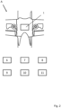
- Figure 2 shows a zoom-in on the bay 1 of the aircraft A already shown in Figure 1 .
- Figure 2 furthermore shows a set of different types of energy modules 6, 7, 8, 9, 10, 11. These energy modules 6 to 11 all have the same dimensions and are configured to fit into the bay 1.
- the energy modules 6 to 11 form a set of energy modules which are interchangeably insertable into the bay 1 of the aircraft A.
- the first energy module 6 is a conventional fuel tank
- the second energy module 7 is a battery
- the third energy module 8 is a fuel tank for a fuel cell
- the fourth energy module 9 is a tank for a nano-electrofuel
- the fifth energy module 10 is a gas tank
- the sixth energy module 11 is a compact energy source.
- the energy modules 6 to 11 form an energy module set.
- the energy module set together with the aircraft A form an aircraft system according to the invention.
- the number of energy modules is not limited to six. In fact, the number of energy modules is theoretically not limited at all.
- the energy module set comprises more than one energy module of at least one energy module type, for example more than one battery 7, more than one conventional fuel tank 6 and/or more than one compact energy source 11. In certain embodiments, the energy module set comprises more than one energy module of all energy module types.
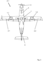
- FIG 3 shows a schematic bottom view of an aircraft A.1 according to a second embodiment of the invention.
- the aircraft A.1 in Figure 3 in principle corresponds to the embodiment already depicted in Figures 1 and 2 .
- the sole difference is that the embodiment shown in Figure 3 comprises two wing-integrated bays 1.1, 1.2, in addition to the fuselage-integrated bay 1 already present in the first embodiment.
- the wing-integrated bays 1.1, 1.2 typically have the same characteristics as the fuselage-mounted bay 1, for example in terms of dimensions, pressurization, connections for modules and the like.
- the technical details given for the fuselage-integrated bay 1 at least partly also apply to the wing-integrated bays 1.1, 1.2.
- the two wing-integrated bays 1.1, 1.2 are typically symmetrically arranged, in particular around a centre of gravity of the aircraft A.1.
- the embodiment shown in Figure 3 makes it possible to carry different energy modules at a time and therefore to further improve the flexibility of the aircraft A.1.
- an aircraft can comprise two, three ore more fuselage-integrated bays and/or two, three or more wing-integrated bays per wing.
- all bays can in principle have the same or at least similar characteristics. It is however also possible that the configurations of the bays differ in such embodiments, for example such that not all bays are configured to receive the same types of energy modules.
- some or all wing-integrated bays can be configured to only carry fuel tanks and/or batteries and/or compact energy sources as energy modules.
- some or all fuselage-integrated bays can be configured to only carry fuel tanks and/or batteries and/or compact energy sources as energy modules.
- Figure 4 shows a schematic bottom view of an aircraft A.2 according to a third embodiment of the invention.
- the aircraft A.2 in Figure 4 in principle corresponds to the aircraft A shown in Figures 1 and 2 .
- the aircraft A.2 instead of a front-mounted turboprop engine, the aircraft A.2 comprises two rear-mounted engines 4.1, 4.2 which are arranged between the two wings 2.1, 2.2 and the tail 5 of the aircraft A.2.
- the functioning of the invention is as follows:
- the aircraft A, A.1 and A.2 are each configured in such a way that they can use energy in different forms, for example electric energy and/or chemical energy and/or energy in the form of conventional fuel for satisfying its energy needs.
- the engines 4 shown in Figures 1 and 3 are hybrid turboprop engines, which are configured such that they can be driven by conventional aircraft fuel, by electric motors or by a combination of both.
- the engines 4.1 and 4.2 shown in Figure 4 are hybrid turbofans, which are configured such that they can be driven by conventional aircraft fuel, by electric motors or by a combination of both.
- the electric motor(s) themselves can be driven for example by batteries or by electric current produced by fuel cells or flow batteries or the like.
- the aircraft A, A.1, A.2 have highly flexible energy management systems and are able to be powered by conventional fuel, battery power or any type of gas or liquid that can serve as fuel in a fuel cell or a flow battery for example.
- the aircraft A, A.1, A.2 each comprise one or more bays 1, 1.1, 1.2, which are configured to receive different types of energy modules, has the advantage to even improve the flexibility of the energy management system of the aircraft.
- a particularly convenient aircraft configuration can be chosen by choosing the appropriate energy module or modules to be placed into the bay(s) 1, 1.1, 1.2.
- the second energy module 7 which corresponds to a battery
- the third energy module 8 in the form of a tank for a fuel cell can be chosen.
- the first energy module 6, corresponding to a conventional fuel tank can be placed inside the bay 1, thereby increasing the amount of conventional aircraft fuel that can be charged into the aircraft A.
Landscapes
- Engineering & Computer Science (AREA)
- Aviation & Aerospace Engineering (AREA)
- Mechanical Engineering (AREA)
- Fuel Cell (AREA)
- Braking Arrangements (AREA)
- Radar Systems Or Details Thereof (AREA)
- Feedback Control In General (AREA)
Claims (14)
- Système aéronautique comprenant :- un aéronef (A, A.1, A.2) comprenant au moins une baie (1, 1.1, 1.2) pour recevoir différents types de modules standardisés,caractérisé en ce que- la baie (1, 1.1, 1.2) est configurée pour recevoir au moins deux types différents de modules énergétiques (6, 7, 8, 9, 10, 11) en tant que modules standardisés, où la baie (1, 1.1, 1.2) comprend des moyens de connexion pour connecter une ou plusieurs interface(s) des modules énergétiques à un système d'alimentation en énergie d'aéronef, la baie (1, 1.1, 1.2) étant configurée pour recevoir tous les différents types de modules énergétiques (6, 7, 8, 9, 10, 11) de manière interchangeable, et- le système aéronautique comprend au moins deux modules énergétiques (6, 7, 8, 9, 10, 11) configurés pour être chargés dans la baie (1, 1.1, 1.2) de l'aéronef (A, A.1, A.2), où un premier module énergétique parmi les au moins deux modules énergétiques (6, 7, 8, 9, 10, 11) comprend un réservoir de carburant conventionnel et où un deuxième module énergétique parmi les au moins deux modules énergétiques (6, 7, 8, 9, 10, 11) comprend une batterie.
- Système aéronautique selon la revendication 1, caractérisé en ce que des modules énergétiques additionnels (6, 7, 8, 9, 10, 11) sont choisis parmi le groupe de modules énergétiques suivant (6, 7, 8, 9, 10, 11): un réservoir de carburant conventionnel, une batterie, un réservoir de carburant pour une pile à combustible, un réservoir pour électrocarburant, un réservoir pour nano-électrocarburant, un réservoir à gaz et/ou une source d'énergie compacte.
- Système aéronautique selon l'une quelconque des revendications précédentes, caractérisé en ce que la baie (1, 1.1, 1.2) est configurée pour recevoir plus de deux parmi les différents types de modules énergétiques (6, 7, 8, 9, 10, 11) de manière interchangeable.
- Système aéronautique selon l'une quelconque des revendications précédentes, caractérisé en ce que la baie (1, 1.1, 1.2) est configurée pour recevoir plus d'un module énergétique (6, 7, 8, 9, 10, 11) à la fois.
- Système aéronautique selon l'une quelconque des revendications précédentes, caractérisé en ce que la baie (1, 1.1, 1.2) est non-pressurisée.
- Système aéronautique selon l'une quelconque des revendications précédentes, caractérisé en ce qu'au moins une baie (1, 1 .1, 1 .2) est située dans et/ou arrangée autour d'un centre de gravité de l'aéronef (A, A.1, A.2).
- Système aéronautique selon l'une quelconque des revendications précédentes, caractérisé en ce qu'au moins une baie (1.1, 1.2) est arrangée au moins en partie à l'intérieur d'une aile (2.1, 2.2) de l'aéronef (A, A.1, A.2).
- Système aéronautique selon l'une quelconque des revendications précédentes, caractérisé en ce que l'aéronef (A, A.1, A.2) est un avion, de préférence un avion d'une longueur inférieure à 40 mètres, typiquement d'une longueur inférieure à 30 mètres, en particulier d'une longueur inférieure à 20 mètres.
- Système aéronautique selon l'une quelconque des revendications précédentes, caractérisé en ce que la baie (1, 1.1 ,1.2) a un volume compris entre 400 litres et 100 litres, de préférence entre 300 et 200 litres, plus préférablement d'environ 250 litres.
- Système aéronautique selon l'une quelconque des revendications précédentes, caractérisé en ce que la baie (1, 1.1, 1.2) est accessible depuis le bas de l'aéronef.
- Système aéronautique selon l'une quelconque des revendications précédentes, caractérisé en ce que toutes les baies (1, 1.1, 1.2) ont essentiellement les mêmes caractéristiques.
- Système aéronautique selon la revendication 2, caractérisé en ce qu'un module énergétique additionnel est un réservoir pour nano-électrocarburant qui comprend un premier réservoir pour un anode-nano-électrocarburant et un deuxième réservoir pour un cathode-nano-électrocarburant.
- Système aéronautique selon l'une quelconque des revendications précédentes, caractérisé en ce que l'aéronef est configuré de telle manière qu'il peut utiliser de l'énergie sous différentes formes pour satisfaire ses besoins énergétiques.
- Système aéronautique selon l'une quelconque des revendications précédentes, caractérisé en ce que l'aéronef comprend: un turbopropulseur hybride (4) ou deux turboréacteurs hybrides (4.1, 4.2).
Priority Applications (1)
| Application Number | Priority Date | Filing Date | Title |
|---|---|---|---|
| EP24182964.7A EP4420984A3 (fr) | 2019-04-11 | 2019-04-11 | Baie énergétique conforme |
Applications Claiming Priority (1)
| Application Number | Priority Date | Filing Date | Title |
|---|---|---|---|
| PCT/IB2019/052988 WO2020208402A1 (fr) | 2019-04-11 | 2019-04-11 | Baie d'énergie conforme |
Related Child Applications (2)
| Application Number | Title | Priority Date | Filing Date |
|---|---|---|---|
| EP24182964.7A Division EP4420984A3 (fr) | 2019-04-11 | 2019-04-11 | Baie énergétique conforme |
| EP24182964.7A Division-Into EP4420984A3 (fr) | 2019-04-11 | 2019-04-11 | Baie énergétique conforme |
Publications (3)
| Publication Number | Publication Date |
|---|---|
| EP3953251A1 EP3953251A1 (fr) | 2022-02-16 |
| EP3953251C0 EP3953251C0 (fr) | 2024-09-18 |
| EP3953251B1 true EP3953251B1 (fr) | 2024-09-18 |
Family
ID=66625214
Family Applications (2)
| Application Number | Title | Priority Date | Filing Date |
|---|---|---|---|
| EP19725403.0A Active EP3953251B1 (fr) | 2019-04-11 | 2019-04-11 | Baie d'énergie conforme |
| EP24182964.7A Pending EP4420984A3 (fr) | 2019-04-11 | 2019-04-11 | Baie énergétique conforme |
Family Applications After (1)
| Application Number | Title | Priority Date | Filing Date |
|---|---|---|---|
| EP24182964.7A Pending EP4420984A3 (fr) | 2019-04-11 | 2019-04-11 | Baie énergétique conforme |
Country Status (4)
| Country | Link |
|---|---|
| US (1) | US20220177153A1 (fr) |
| EP (2) | EP3953251B1 (fr) |
| BR (3) | BR122023022025A2 (fr) |
| WO (1) | WO2020208402A1 (fr) |
Families Citing this family (3)
| Publication number | Priority date | Publication date | Assignee | Title |
|---|---|---|---|---|
| US12528591B1 (en) * | 2021-01-27 | 2026-01-20 | Piasecki Aircraft Corporation | Aircraft power module and ground handling system, method and apparatus |
| US12085216B2 (en) | 2022-02-17 | 2024-09-10 | Arctic Cat Inc. | Multi-use fuel filler tube |
| DE102022120468A1 (de) | 2022-08-12 | 2022-09-29 | Daimler Truck AG | Elektrischer Energiespeicher für ein zumindest teilweise elektrisch betriebenes Kraftfahrzeug sowie Verfahren |
Family Cites Families (15)
| Publication number | Priority date | Publication date | Assignee | Title |
|---|---|---|---|---|
| GB2326863A (en) * | 1997-04-11 | 1999-01-06 | Stuart Charles Aiken | Modular cargo/passenger units for aircraft |
| DE10310373A1 (de) * | 2003-02-07 | 2004-08-19 | Göritz, Axel | System zur Minimierung von Brandschäden in Verkehrs- und Transportflugzeugen bei Notlandungen und Terroranschlägen und anderen Unglücken |
| US20080184906A1 (en) * | 2007-02-07 | 2008-08-07 | Kejha Joseph B | Long range hybrid electric airplane |
| DE102007062873B4 (de) * | 2007-12-28 | 2014-03-27 | Airbus Operations Gmbh | Luftfrachtcontainer und Flugzeug |
| US8393580B2 (en) * | 2008-09-12 | 2013-03-12 | The Boeing Company | Modular externally accessible batteries for an aircraft |
| US9731810B1 (en) * | 2014-09-22 | 2017-08-15 | Robertson Fuel Systems, L.L.C. | System and method for improving fuel storage within a wing of an aircraft |
| CA2876858C (fr) * | 2014-12-24 | 2017-03-14 | Airbus Helicopters | Dispositif de fixation d'un reservoir souple dans un compartiment |
| US10618661B2 (en) * | 2015-02-23 | 2020-04-14 | Airbus Operations Gmbh | On-board removable container for cooling cargo materials and equipment in aircraft |
| US10640215B2 (en) * | 2016-09-20 | 2020-05-05 | Textron Innovations Inc. | Modular refueling systems for aircraft |
| EP3601042B1 (fr) * | 2017-03-22 | 2024-03-13 | Aurora Flight Sciences Corporation | Système aérien sans pilote modulaire multi-architecture |
| US10378452B1 (en) * | 2018-02-26 | 2019-08-13 | The Boeing Company | Hybrid turbine jet engines and methods of operating the same |
| CA3132012A1 (fr) * | 2019-03-01 | 2020-09-10 | Frank Becker | Aeronef comportant un systeme de propulsion electrique hybride a accumulateur electrique situe dans les ailes |
| US11661172B2 (en) * | 2020-12-31 | 2023-05-30 | Textron Innovations Inc. | Wing design for removable battery |
| US11597528B2 (en) * | 2021-06-16 | 2023-03-07 | Joby Aero, Inc. | Aircraft energy storage mounting system |
| CN114933010B (zh) * | 2022-07-08 | 2025-04-29 | 西安交通大学 | 一种基于赋形燃料电池组件的机翼动力一体化装置 |
-
2019
- 2019-04-11 EP EP19725403.0A patent/EP3953251B1/fr active Active
- 2019-04-11 BR BR122023022025-0A patent/BR122023022025A2/pt unknown
- 2019-04-11 US US17/602,933 patent/US20220177153A1/en active Pending
- 2019-04-11 WO PCT/IB2019/052988 patent/WO2020208402A1/fr not_active Ceased
- 2019-04-11 BR BR122023022026-9A patent/BR122023022026A2/pt unknown
- 2019-04-11 EP EP24182964.7A patent/EP4420984A3/fr active Pending
- 2019-04-11 BR BR122023022028-5A patent/BR122023022028A2/pt unknown
Also Published As
| Publication number | Publication date |
|---|---|
| EP3953251C0 (fr) | 2024-09-18 |
| WO2020208402A1 (fr) | 2020-10-15 |
| EP4420984A3 (fr) | 2024-10-09 |
| EP3953251A1 (fr) | 2022-02-16 |
| BR122023022025A2 (pt) | 2024-01-16 |
| BR122023022028A2 (pt) | 2024-01-16 |
| BR122023022026A2 (pt) | 2024-01-16 |
| BR112021020313A2 (pt) | 2021-12-14 |
| EP4420984A2 (fr) | 2024-08-28 |
| US20220177153A1 (en) | 2022-06-09 |
Similar Documents
| Publication | Publication Date | Title |
|---|---|---|
| AU2017415649B2 (en) | Electric vehicle hybrid battery system | |
| US11434014B2 (en) | Aircraft spars with integrated power cells, and associated systems and methods | |
| US8511613B2 (en) | Modular externally accessible batteries for an aircraft | |
| US8469306B2 (en) | Purebred and hybrid electric VTOL tilt rotor aircraft | |
| EP3953251B1 (fr) | Baie d'énergie conforme | |
| US20180319283A1 (en) | Aircraft Power System | |
| US8722272B2 (en) | Modular fuel cell system module for connection to an aircraft fuselage | |
| EP3326917A1 (fr) | Élément structural, bloc batterie, disposition d'un élément structural et bloc batterie et véhicule aérospatial | |
| US20240166331A1 (en) | Aircraft wing with fuel tank and fuel cell | |
| CN107264792A (zh) | 一种动力系统模块化的无人机 | |
| HK40115873A (en) | Conformal energy bay | |
| HK40069036B (en) | Conformal energy bay | |
| HK40069036A (en) | Conformal energy bay | |
| Baldic et al. | Fuel cell systems for long duration electric UAVs and UGVs | |
| Friend et al. | Fuel Cell Powered Demonstrator Airplane | |
| BR112021020313B1 (pt) | Compartimento de energia conformal | |
| KR102029664B1 (ko) | 연료전지를 위한 카트리지형 결속구조, 및 이를 포함하는 연료전지 충전시스템 | |
| US20180319288A1 (en) | Ethanol-Fueled Fuel Cell Powered Aircraft | |
| US20230415904A1 (en) | Method for converting an airplane with thermic reaction propulsion motor to electrical reaction propulsion airplane and the electric airplane thereof | |
| US20240400227A1 (en) | On-ground aircraft service system | |
| EP4691911A1 (fr) | Système de service d'aéronef au sol | |
| US12448135B2 (en) | Hydrogen-solar integrated energy system and method for aircraft | |
| CN115477019B (zh) | 一种模块化氢能源无人机 | |
| NZ759465B2 (en) | Electric vehicle hybrid battery system |
Legal Events
| Date | Code | Title | Description |
|---|---|---|---|
| STAA | Information on the status of an ep patent application or granted ep patent |
Free format text: STATUS: UNKNOWN |
|
| STAA | Information on the status of an ep patent application or granted ep patent |
Free format text: STATUS: THE INTERNATIONAL PUBLICATION HAS BEEN MADE |
|
| PUAI | Public reference made under article 153(3) epc to a published international application that has entered the european phase |
Free format text: ORIGINAL CODE: 0009012 |
|
| STAA | Information on the status of an ep patent application or granted ep patent |
Free format text: STATUS: REQUEST FOR EXAMINATION WAS MADE |
|
| 17P | Request for examination filed |
Effective date: 20211111 |
|
| AK | Designated contracting states |
Kind code of ref document: A1 Designated state(s): AL AT BE BG CH CY CZ DE DK EE ES FI FR GB GR HR HU IE IS IT LI LT LU LV MC MK MT NL NO PL PT RO RS SE SI SK SM TR |
|
| DAV | Request for validation of the european patent (deleted) | ||
| DAX | Request for extension of the european patent (deleted) | ||
| REG | Reference to a national code |
Ref country code: HK Ref legal event code: DE Ref document number: 40069036 Country of ref document: HK |
|
| RIC1 | Information provided on ipc code assigned before grant |
Ipc: B64D 27/02 20060101ALI20230810BHEP Ipc: B64D 37/08 20060101ALI20230810BHEP Ipc: B64D 9/00 20060101ALI20230810BHEP Ipc: B64C 1/22 20060101AFI20230810BHEP |
|
| GRAP | Despatch of communication of intention to grant a patent |
Free format text: ORIGINAL CODE: EPIDOSNIGR1 |
|
| STAA | Information on the status of an ep patent application or granted ep patent |
Free format text: STATUS: GRANT OF PATENT IS INTENDED |
|
| INTG | Intention to grant announced |
Effective date: 20231017 |
|
| RAP3 | Party data changed (applicant data changed or rights of an application transferred) |
Owner name: PILATUS FLUGZEUGWERKE AG |
|
| GRAS | Grant fee paid |
Free format text: ORIGINAL CODE: EPIDOSNIGR3 |
|
| GRAA | (expected) grant |
Free format text: ORIGINAL CODE: 0009210 |
|
| STAA | Information on the status of an ep patent application or granted ep patent |
Free format text: STATUS: THE PATENT HAS BEEN GRANTED |
|
| AK | Designated contracting states |
Kind code of ref document: B1 Designated state(s): AL AT BE BG CH CY CZ DE DK EE ES FI FR GB GR HR HU IE IS IT LI LT LU LV MC MK MT NL NO PL PT RO RS SE SI SK SM TR |
|
| REG | Reference to a national code |
Ref country code: GB Ref legal event code: FG4D |
|
| REG | Reference to a national code |
Ref country code: CH Ref legal event code: EP |
|
| REG | Reference to a national code |
Ref country code: DE Ref legal event code: R096 Ref document number: 602019059063 Country of ref document: DE |
|
| REG | Reference to a national code |
Ref country code: IE Ref legal event code: FG4D |
|
| U01 | Request for unitary effect filed |
Effective date: 20241017 |
|
| U07 | Unitary effect registered |
Designated state(s): AT BE BG DE DK EE FI FR IT LT LU LV MT NL PT RO SE SI Effective date: 20241202 |
|
| PG25 | Lapsed in a contracting state [announced via postgrant information from national office to epo] |
Ref country code: NO Free format text: LAPSE BECAUSE OF FAILURE TO SUBMIT A TRANSLATION OF THE DESCRIPTION OR TO PAY THE FEE WITHIN THE PRESCRIBED TIME-LIMIT Effective date: 20241218 |
|
| PG25 | Lapsed in a contracting state [announced via postgrant information from national office to epo] |
Ref country code: GR Free format text: LAPSE BECAUSE OF FAILURE TO SUBMIT A TRANSLATION OF THE DESCRIPTION OR TO PAY THE FEE WITHIN THE PRESCRIBED TIME-LIMIT Effective date: 20241219 |
|
| PG25 | Lapsed in a contracting state [announced via postgrant information from national office to epo] |
Ref country code: HR Free format text: LAPSE BECAUSE OF FAILURE TO SUBMIT A TRANSLATION OF THE DESCRIPTION OR TO PAY THE FEE WITHIN THE PRESCRIBED TIME-LIMIT Effective date: 20240918 |
|
| PG25 | Lapsed in a contracting state [announced via postgrant information from national office to epo] |
Ref country code: RS Free format text: LAPSE BECAUSE OF FAILURE TO SUBMIT A TRANSLATION OF THE DESCRIPTION OR TO PAY THE FEE WITHIN THE PRESCRIBED TIME-LIMIT Effective date: 20241218 |
|
| PG25 | Lapsed in a contracting state [announced via postgrant information from national office to epo] |
Ref country code: RS Free format text: LAPSE BECAUSE OF FAILURE TO SUBMIT A TRANSLATION OF THE DESCRIPTION OR TO PAY THE FEE WITHIN THE PRESCRIBED TIME-LIMIT Effective date: 20241218 Ref country code: NO Free format text: LAPSE BECAUSE OF FAILURE TO SUBMIT A TRANSLATION OF THE DESCRIPTION OR TO PAY THE FEE WITHIN THE PRESCRIBED TIME-LIMIT Effective date: 20241218 Ref country code: HR Free format text: LAPSE BECAUSE OF FAILURE TO SUBMIT A TRANSLATION OF THE DESCRIPTION OR TO PAY THE FEE WITHIN THE PRESCRIBED TIME-LIMIT Effective date: 20240918 Ref country code: GR Free format text: LAPSE BECAUSE OF FAILURE TO SUBMIT A TRANSLATION OF THE DESCRIPTION OR TO PAY THE FEE WITHIN THE PRESCRIBED TIME-LIMIT Effective date: 20241219 |
|
| PG25 | Lapsed in a contracting state [announced via postgrant information from national office to epo] |
Ref country code: IS Free format text: LAPSE BECAUSE OF FAILURE TO SUBMIT A TRANSLATION OF THE DESCRIPTION OR TO PAY THE FEE WITHIN THE PRESCRIBED TIME-LIMIT Effective date: 20250118 |
|
| PG25 | Lapsed in a contracting state [announced via postgrant information from national office to epo] |
Ref country code: SM Free format text: LAPSE BECAUSE OF FAILURE TO SUBMIT A TRANSLATION OF THE DESCRIPTION OR TO PAY THE FEE WITHIN THE PRESCRIBED TIME-LIMIT Effective date: 20240918 |
|
| PG25 | Lapsed in a contracting state [announced via postgrant information from national office to epo] |
Ref country code: ES Free format text: LAPSE BECAUSE OF FAILURE TO SUBMIT A TRANSLATION OF THE DESCRIPTION OR TO PAY THE FEE WITHIN THE PRESCRIBED TIME-LIMIT Effective date: 20240918 |
|
| PG25 | Lapsed in a contracting state [announced via postgrant information from national office to epo] |
Ref country code: CZ Free format text: LAPSE BECAUSE OF FAILURE TO SUBMIT A TRANSLATION OF THE DESCRIPTION OR TO PAY THE FEE WITHIN THE PRESCRIBED TIME-LIMIT Effective date: 20240918 Ref country code: PL Free format text: LAPSE BECAUSE OF FAILURE TO SUBMIT A TRANSLATION OF THE DESCRIPTION OR TO PAY THE FEE WITHIN THE PRESCRIBED TIME-LIMIT Effective date: 20240918 |
|
| PG25 | Lapsed in a contracting state [announced via postgrant information from national office to epo] |
Ref country code: SK Free format text: LAPSE BECAUSE OF FAILURE TO SUBMIT A TRANSLATION OF THE DESCRIPTION OR TO PAY THE FEE WITHIN THE PRESCRIBED TIME-LIMIT Effective date: 20240918 |
|
| U20 | Renewal fee for the european patent with unitary effect paid |
Year of fee payment: 7 Effective date: 20250430 |
|
| PGFP | Annual fee paid to national office [announced via postgrant information from national office to epo] |
Ref country code: MC Payment date: 20250430 Year of fee payment: 7 |
|
| PGFP | Annual fee paid to national office [announced via postgrant information from national office to epo] |
Ref country code: GB Payment date: 20250430 Year of fee payment: 7 |
|
| PLBE | No opposition filed within time limit |
Free format text: ORIGINAL CODE: 0009261 |
|
| STAA | Information on the status of an ep patent application or granted ep patent |
Free format text: STATUS: NO OPPOSITION FILED WITHIN TIME LIMIT |
|
| PGFP | Annual fee paid to national office [announced via postgrant information from national office to epo] |
Ref country code: IE Payment date: 20250430 Year of fee payment: 7 |
|
| 26N | No opposition filed |
Effective date: 20250619 |
|
| PGFP | Annual fee paid to national office [announced via postgrant information from national office to epo] |
Ref country code: CH Payment date: 20250731 Year of fee payment: 7 |