EP3953600B1 - Plaquette de frein pour un véhicule, agencement de frein, système de freinage et véhicule - Google Patents
Plaquette de frein pour un véhicule, agencement de frein, système de freinage et véhicule Download PDFInfo
- Publication number
- EP3953600B1 EP3953600B1 EP19719450.9A EP19719450A EP3953600B1 EP 3953600 B1 EP3953600 B1 EP 3953600B1 EP 19719450 A EP19719450 A EP 19719450A EP 3953600 B1 EP3953600 B1 EP 3953600B1
- Authority
- EP
- European Patent Office
- Prior art keywords
- brake
- brake pad
- sliding portion
- brake disc
- pad
- Prior art date
- Legal status (The legal status is an assumption and is not a legal conclusion. Google has not performed a legal analysis and makes no representation as to the accuracy of the status listed.)
- Active
Links
Images




Classifications
-
- F—MECHANICAL ENGINEERING; LIGHTING; HEATING; WEAPONS; BLASTING
- F16—ENGINEERING ELEMENTS AND UNITS; GENERAL MEASURES FOR PRODUCING AND MAINTAINING EFFECTIVE FUNCTIONING OF MACHINES OR INSTALLATIONS; THERMAL INSULATION IN GENERAL
- F16D—COUPLINGS FOR TRANSMITTING ROTATION; CLUTCHES; BRAKES
- F16D55/00—Brakes with substantially-radial braking surfaces pressed together in axial direction, e.g. disc brakes
- F16D55/02—Brakes with substantially-radial braking surfaces pressed together in axial direction, e.g. disc brakes with axially-movable discs or pads pressed against axially-located rotating members
- F16D55/22—Brakes with substantially-radial braking surfaces pressed together in axial direction, e.g. disc brakes with axially-movable discs or pads pressed against axially-located rotating members by clamping an axially-located rotating disc between movable braking members, e.g. movable brake discs or brake pads
- F16D55/224—Brakes with substantially-radial braking surfaces pressed together in axial direction, e.g. disc brakes with axially-movable discs or pads pressed against axially-located rotating members by clamping an axially-located rotating disc between movable braking members, e.g. movable brake discs or brake pads with a common actuating member for the braking members
- F16D55/225—Brakes with substantially-radial braking surfaces pressed together in axial direction, e.g. disc brakes with axially-movable discs or pads pressed against axially-located rotating members by clamping an axially-located rotating disc between movable braking members, e.g. movable brake discs or brake pads with a common actuating member for the braking members the braking members being brake pads
- F16D55/226—Brakes with substantially-radial braking surfaces pressed together in axial direction, e.g. disc brakes with axially-movable discs or pads pressed against axially-located rotating members by clamping an axially-located rotating disc between movable braking members, e.g. movable brake discs or brake pads with a common actuating member for the braking members the braking members being brake pads in which the common actuating member is moved axially, e.g. floating caliper disc brakes
- F16D55/2265—Brakes with substantially-radial braking surfaces pressed together in axial direction, e.g. disc brakes with axially-movable discs or pads pressed against axially-located rotating members by clamping an axially-located rotating disc between movable braking members, e.g. movable brake discs or brake pads with a common actuating member for the braking members the braking members being brake pads in which the common actuating member is moved axially, e.g. floating caliper disc brakes the axial movement being guided by one or more pins engaging bores in the brake support or the brake housing
- F16D55/227—Brakes with substantially-radial braking surfaces pressed together in axial direction, e.g. disc brakes with axially-movable discs or pads pressed against axially-located rotating members by clamping an axially-located rotating disc between movable braking members, e.g. movable brake discs or brake pads with a common actuating member for the braking members the braking members being brake pads in which the common actuating member is moved axially, e.g. floating caliper disc brakes the axial movement being guided by one or more pins engaging bores in the brake support or the brake housing by two or more pins
-
- F—MECHANICAL ENGINEERING; LIGHTING; HEATING; WEAPONS; BLASTING
- F16—ENGINEERING ELEMENTS AND UNITS; GENERAL MEASURES FOR PRODUCING AND MAINTAINING EFFECTIVE FUNCTIONING OF MACHINES OR INSTALLATIONS; THERMAL INSULATION IN GENERAL
- F16D—COUPLINGS FOR TRANSMITTING ROTATION; CLUTCHES; BRAKES
- F16D65/00—Parts or details
- F16D65/0006—Noise or vibration control
-
- F—MECHANICAL ENGINEERING; LIGHTING; HEATING; WEAPONS; BLASTING
- F16—ENGINEERING ELEMENTS AND UNITS; GENERAL MEASURES FOR PRODUCING AND MAINTAINING EFFECTIVE FUNCTIONING OF MACHINES OR INSTALLATIONS; THERMAL INSULATION IN GENERAL
- F16D—COUPLINGS FOR TRANSMITTING ROTATION; CLUTCHES; BRAKES
- F16D65/00—Parts or details
- F16D65/02—Braking members; Mounting thereof
- F16D65/04—Bands, shoes or pads; Pivots or supporting members therefor
- F16D65/092—Bands, shoes or pads; Pivots or supporting members therefor for axially-engaging brakes, e.g. disc brakes
- F16D65/095—Pivots or supporting members therefor
- F16D65/097—Resilient means interposed between pads and supporting members or other brake parts
- F16D65/0973—Resilient means interposed between pads and supporting members or other brake parts not subjected to brake forces
- F16D65/0974—Resilient means interposed between pads and supporting members or other brake parts not subjected to brake forces acting on or in the vicinity of the pad rim in a direction substantially transverse to the brake disc axis
- F16D65/0977—Springs made from sheet metal
- F16D65/0978—Springs made from sheet metal acting on one pad only
-
- F—MECHANICAL ENGINEERING; LIGHTING; HEATING; WEAPONS; BLASTING
- F16—ENGINEERING ELEMENTS AND UNITS; GENERAL MEASURES FOR PRODUCING AND MAINTAINING EFFECTIVE FUNCTIONING OF MACHINES OR INSTALLATIONS; THERMAL INSULATION IN GENERAL
- F16D—COUPLINGS FOR TRANSMITTING ROTATION; CLUTCHES; BRAKES
- F16D55/00—Brakes with substantially-radial braking surfaces pressed together in axial direction, e.g. disc brakes
- F16D2055/0004—Parts or details of disc brakes
- F16D2055/0016—Brake calipers
-
- F—MECHANICAL ENGINEERING; LIGHTING; HEATING; WEAPONS; BLASTING
- F16—ENGINEERING ELEMENTS AND UNITS; GENERAL MEASURES FOR PRODUCING AND MAINTAINING EFFECTIVE FUNCTIONING OF MACHINES OR INSTALLATIONS; THERMAL INSULATION IN GENERAL
- F16D—COUPLINGS FOR TRANSMITTING ROTATION; CLUTCHES; BRAKES
- F16D55/00—Brakes with substantially-radial braking surfaces pressed together in axial direction, e.g. disc brakes
- F16D2055/0004—Parts or details of disc brakes
- F16D2055/0016—Brake calipers
- F16D2055/0029—Retraction devices
Definitions
- the invention relates to a brake pad for a vehicle, adapted to be connected to a carrier around a rotatable brake disc.
- the invention also relates to a brake arrangement comprising such a brake pad and a carrier.
- the invention further relates to a brake system comprising such a brake arrangement and a brake disc.
- the invention also relates to a vehicle comprising such a brake pad, such a brake arrangement or such a brake system.
- the invention can be applied in heavy-duty vehicles, such as trucks, buses and construction equipment. Although the invention will be described with respect to a truck, the invention is not restricted to this particular vehicle, but may also be used in other vehicles such as cars.
- Disc brakes are available in different forms and variants.
- a calliper is used for pressing or squeezing brake pads against a brake disc to create friction. The friction slows down the rotation of the vehicle axle to which the brake disc is connected, thereby reducing the speed of the vehicle.
- fluid pressure activates and forces the brake pads towards the brake disc.
- the calliper is deflected during brake application and springs back into its original position after brake release.
- the brake pads may not fully retract after the brake is released. This lead to a residual contact between the brake pad and the brake disc and hence generates drag. This drag affects fuel efficiency and increases the wear of the brake pad and brake disc.
- the disc brake is designed to reduce noise.
- the disc brake comprises a pad assembly adapted to be urged against a disc by a brake motor.
- the pad assembly comprises a lining block of friction material which is attached to a support plate.
- the support plate has lateral ends which slide in, and are circumferentially retained by, a fixed support for their reception. However, even though the lateral ends may slide in the circumferential support, the problem of drag is not solved by such a design.
- An object of the invention is to provide a brake pad which alleviates the above-mentioned drawback of the prior art.
- a brake pad for a vehicle.
- the brake pad is adapted to be connected to a carrier around a rotatable brake disc which rotates around a geometrical centre axis.
- the brake pad comprises:
- the geometrical design of the sliding portion is also advantageous because it allows retraction of the brake pad without any extra retracting mechanisms, instead the inventive configuration takes advantage of gravitation, which may be assisted by vibrations, such as axle vibrations.
- the upper and lower sides of the brake pad may have a relatively longer extension and the lower side is intended to face the geometrical centre axis of the brake disc.
- the upper and lower sides of the brake pad may have a relatively shorter extension and a lateral side may instead be intended to face the geometrical centre axis of the brake disc (such a lateral side would suitably interconnect the upper and lower sides and would suitably also interconnect the friction surface and the opposite surface).
- the at least one sliding portion extends obliquely downwards towards the opposite surface.
- An oblique inclination is a simple way to manufacture a downwardly extending sliding portion.
- the at least one sliding portion extends in a curvature (for instance the sliding portion may have a radius) downwards towards the opposite surface. This may be advantageous if, for instance, mated with a non-curved sliding portion of a carrier, in which case there would be a line contact instead of an area contact between the mating sliding portions, thereby reducing the friction between the mating sliding portions.
- the brake pad comprises a backing part and a consumable lining part fixedly mounted to the backing part, wherein the friction surface is provided on the lining part and the opposite surface is provided on the backing part, wherein the downwardly extending sliding portion is formed by both the backing part and the lining part.
- the at least one sliding portion extends from the friction surface to the opposite surface, thereby interconnecting the friction surface with the opposite surface.
- This is advantageous as the tapering of the sliding portion may extend all the way from one side to the other side.
- the sliding portion does not need to cover the entire lower side.
- the sliding portion may form one or more tapering band-like portions across the lower side of the brake pad, i.e. extending from the friction surface to the opposite surface, while other portions of the lower side may or may not be tapering.
- the entire lower side may be a tapering sliding portion.
- the friction surface extends in a geometrical plane, wherein the at least one sliding portion extends at an angle of 3° - 45°, such as 5° - 30°, for example 7° - 15° relative to a normal to said geometrical plane. Said ranges have been found advantageous for returning the brake pad after release of the brake pedal by means of gravitation assisted by any vibration.
- the brake pad comprises at least two sliding portions spaced apart from each other.
- said two sliding portions are located on respective sides of a plane of symmetry of the brake pad. This may provide for a balanced and stable retraction, and by not having the entire lower side presenting a sliding portion, the friction between the brake pad and a carrier on which the brake pad is to be mounted may be reduced, thereby improving the sliding ability.
- the upper side is adapted to face away from a geometrical centre axis of a brake disc, wherein the lower side is adapted to face in a direction towards said geometrical centre axis, wherein the friction surface is adapted to be pressed against the brake disc above said geometrical centre axis.
- This configuration of the brake pad is suitable for use in a calliper intended to be mounted at the top of the brake disc.
- the brake pad comprises a lateral side extending in one direction from the upper side to the lower side and extending in another direction from the friction surface to the opposite surface, wherein the lateral side is adapted to face in a direction towards said geometrical centre axis.
- This configuration of the brake pad is suitable for use in a calliper intended to be mounted at a lateral side of the brake disc (i.e. along the periphery of the brake disc between the top and bottom of the brake disc, which is popularly referred to as at "3 o'clock” or at "9 o'clock”).
- a brake arrangement comprising a brake pad of the first aspect of the invention and a carrier adapted to be mounted to a rotatable brake disc, wherein the sliding portion of the brake pad is a first sliding portion, wherein the carrier comprises a second sliding portion mating with the first sliding portion, wherein the brake pad with the first sliding portion is enabled to slide along the second sliding portion towards and away from the brake disc.
- the second sliding portion (i.e. of the carrier) and the first sliding portion (i.e. of the brake pad) have the same angle of inclination relative to the friction surface of the brake pad.
- a continuous interface may be obtained between the sliding portions, whereby an efficient movement of the brake pad along the carrier and away from the brake disc is achievable.
- the brake arrangement may have a brake pad with a sliding portion having a curved extension downwards towards the opposite surface, mating with a non-curved or differently curved sliding portion of the carrier, whereby a line contact between the first sliding portion and the second sliding portion is obtained, thereby reducing the friction between the first and second sliding portions.
- the brake arrangement further comprises a spring element urging the first sliding portion against the second sliding portion by a downwardly directed spring force. This is advantageous in that an extra force is provided in addition to vibrational and/or gravitational forces, thereby further improving the retraction of the brake pad from the brake disc after a driver has released the brake pedal.
- a brake system comprising a brake arrangement of the second aspect and a brake disc which is rotatable around a geometrical centre axis, wherein the carrier is mounted so as to enable the friction surface of the brake pad to be pressed against the brake disc when the brake pad is subjected to a force directed towards the brake disc.
- the first sliding portion and the second sliding portion taper downwardly, such as towards the geometrical centre axis as seen in a direction facing away from the brake disc, wherein the tapering enables the brake pad to move away from the brake disc due to vibrations and/or gravitation.
- the sliding portion will taper downwardly as it extends from the friction surface to the opposite surface.
- the object is achieved by a vehicle according to claim 16.
- a brake pad of the first aspect a brake arrangement of the second aspect, or a brake system of the third aspect.
- Fig. 1 is a schematic illustration of a vehicle 2, in accordance with at least one exemplary embodiment of the invention.
- vehicle 2 is illustrated in the form of a truck, other types of vehicles, such as busses, construction equipment, trailers or passenger cars may be provided in accordance with the invention.
- the truck comprises a cab 4 in which a driver may operate the vehicle.
- the vehicle comprises a number of road wheels 6, herein illustrated as three pairs of wheels, however in other embodiments there may be a different number of wheels, such as two pairs, four pairs or more.
- a driver may press a brake pedal with his/her foot in order to activate the brake or brakes. Activation of the brake causes brake pads to be pressed against a brake disc (not illustrated in Fig. 1 ) connected to an axle that rotates the road wheels.
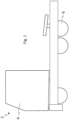
- Figs. 2a-2c illustrate a brake pad 10 in accordance with at least one exemplary embodiment of the invention.
- Fig. 2a is an end view of the brake pad 10
- Fig. 2b is a perspective view from above
- Fig. 2c is a perspective view from below.
- the brake pad 10 is intended to be used in a vehicle, such as a vehicle schematically exemplified in Fig. 1 . More specifically, the brake pad 10 is adapted to be connected to a carrier around a rotatable brake disc which rotates around a geometrical centre axis.
- the brake pad 10 comprises an upper side 12 adapted to face away from a geometrical centre axis of a brake disc.
- the upper side 12 When a vehicle stands on horizontal ground, the upper side 12 will be at a higher horizontal level than the geometrical centre axis of the brake disc, and thus at a higher level than the wheel axle.
- the upper side 12 will be directed away from the ground, facing upwards.
- the upper side 12 does not need to be confined to one horizontal plane, but may have different levels all facing upwards.
- the brake pad 10 comprises a lower side 14 adapted to face in a direction towards said geometrical centre axis.
- the upper side 12 and the lower side 14 face in substantially opposite directions.
- a friction surface 16 extends downwardly from the upper side 12 to the lower side 14 and is adapted to be pressed against a brake disc above said geometrical centre axis.
- the material of the friction surface 16 may for instance comprise non-metallic materials, such as synthetic substances bonded into a composite, or semi-metallic materials, such as synthetics mixed with varying proportions of flaked metals, or ceramic materials, or fully metallic materials.
- the frictions surface 16 is adapted to face the brake disc.
- the opposite surface 18 is adapted to be faced away from the brake disc.
- the lower side 14 comprises at least one sliding portion 20 configured to slide against a mating sliding portion of a carrier.
- the at least one sliding portion 20 extends obliquely downwards towards the opposite surface.
- the brake pad 10 comprises a backing part 22 and a consumable lining part 24 fixedly mounted to the backing part 22, wherein the friction surface 16 is provided on the lining part 24 and the opposite surface 18 is provided on the backing part 22, wherein the obliquely extending sliding portions 20 are formed by both the backing part 22 and the lining part 24.
- the backing part 22 and the consumable lining part 24 may have substantially the same thickness, or as illustrated in Fig. 2a , the consumable lining part 24 may be somewhat thicker than the backing part 22.
- the friction surface 16 may suitably be formed by the consumable lining part 24.
- the backing part 22 may, for instance, be made of metal, such as steel.
- the backing part 22 may be regarded as a backing plate providing support to the consumable friction material, the lining part 24.
- each sliding portion 20 may thus, in at least some exemplary embodiments, comprise two or more different material portions, one formed by the backing part 22 and one formed by the lining part 24.
- the two sliding portions 20 are located on respective sides of a plane of symmetry of the brake pad 10.
- the two sliding portions 20 of the brake pad 10 are separated by an arched portion 26.
- Such an arched portion 26 may contribute to appropriate stability and/or balancing of the brake pad 10 when mounted on a carrier.
- the arched portion 26 may suitably have a contour which follows the contour of a corresponding arched portion of a carrier on which the brake pad 10 is to be mounted. In at least some exemplary embodiments, the arched portion 26 does not, contrary to the sliding portions 20, extend downwardly from the friction surface 16 towards the opposite surface 18. However, in other exemplary embodiments, the arched portion 26 may, similarly to the sliding portions 20, extend downwardly from the friction surface 16 towards the opposite surface 18.
- the sliding portions 20 constitute less than 75%, suitably less than 50% of the total area of the lower side 14 of the brake pad 10. According, to at least some exemplary embodiments, each individual continuous (i.e. non-interrupted) sliding portion 20 constitutes less than 50%, suitably less than 30% of the total area of the lower side 14. This provides for low sliding friction between the brake pad 10 and the carrier on which the brake pad 10 is to be mounted.
- the sliding portions 20 extend all the way from the friction surface 16 to the opposite surface 18, thereby interconnecting the friction surface 16 with the opposite surface 18.
- the sliding portion 20 or sliding portions 20 may extend only part of the way between the friction surface 16 and the opposite surface 18.
- the friction surface 16 lies in a geometrical plane, wherein the at least one sliding portion extends at an angle ⁇ of 3° - 45°, such as 5° - 30°, for example 7° - 15° relative to a normal to said geometrical plane.
- the brake pad 10 is configured to be mounted such that said angle ⁇ is formed relative to the horizontal ground surface, and thus, relative to the central geometrical axis extending through the brake disc.
- the friction surface 16 may extend in more than one geometric plane, however, each of the geometric planes extend in a vertical direction, i.e. upwardly from the lower side 14 to the upper side 12 of the brake pad 10.
- the above mentioned angle ⁇ relative to the normal will therefore be the same irrespective of which one of the geometrical planes the normal is taken from.
- an optional spring element 28 is illustrated as being connected to upwardly projecting connectors 30 of the backing part 22.
- the spring element 28 may assist in urging the brake pad 10 into a retracted position after the driver has released the brake pedal.
- the spring element 28 is intended to provide a downwardly directed force, i.e. supplementing the downwardly directed gravitational force.
- the spring element 28 may be omitted, as the inclination of the sliding portions 20 is enough for achieving the desired retraction, due to gravitational force and any vibrational forces conveyed for instance from the axle of the road wheel.
- other spring element configurations may be provided, which are connected differently to the backing part 22 or to some other part of a brake arrangement.
- first sliding portions 20 of the brake pad will be referred to as first sliding portions 20, in order to avoid confusion when discussing herein below sliding portions of a carrier, the latter ones will be referred to as second sliding portions.
- Fig. 3 illustrates a carrier 40 for use in a brake arrangement in accordance with at least one exemplary embodiment of the invention.
- a brake arrangement comprises a carrier (such as carrier 40 in Fig. 3 ) and a brake pad (such as brake pad 10 in Figs. 2a-2c ).
- the carrier 40 comprises an inner part 42 and an outer part 44.
- the inner part 42 is adapted to be positioned on an inner side of the brake disc, i.e. on the side closest to the centre of the vehicle.
- the outer part 44 is adapted to be positioned on an outer side of the brake disc, i.e. on the side farthest from the centre of the vehicle.
- Each one of the inner part 42 and the outer part 44 has a pair of sliding portions 50, herein referred to as second sliding portions 50 (in order to differentiate them from the sliding portions of the brake pad, such as the brake pad of Fig. 1 , which may be referred to as first sliding portions 20).
- Each pair of second sliding portions 50 are separated by a distance which corresponds to the separating distance between the first sliding portions of the brake pad.
- the second sliding portions 50 of the carrier 40 are configured to receive first sliding portions of a brake pad, and allow said first sliding portions to slide along the second sliding portions 50.
- the inner part 42 of the carrier 40 will support one brake pad, while the outer part 44 of the a carrier 40 will support another brake pad.
- the two brake pads will be enabled to slide on the second sliding portions 50 towards the brake disc in order to squeeze the brake disc in between the brake pads, when a driver applies the brake of the vehicle, and the two brake pads will be enabled to slide away from the brake disc to a retracted position when the driver releases the brake.
- the second sliding portions 50 on the inner part 42 of the carrier 40 taper downwardly in a direction extending from the outer side towards the inner side of the brake disc, i.e. in a direction away from the brake disc and towards the centre of the vehicle.
- the second sliding portions 50 on the outer part 44 of the carrier taper downwardly in a direction extending from the inner side towards the outer side of the brake disc, i.e. in a direction away from the brake disc and away from the centre of the vehicle.
- the two pairs of second sliding portions 50 taper in opposite directions, both being directions away from the brake disc which is intended to be interposed between the two pairs of second sliding portions 50.
- Both the inner part 42 and the outer part 44 of the carrier 40 comprise a respective arched portion 46, which separate the second sliding portions 50 from each other in each pair of second sliding portions 50.
- the arched portions 46 of the carrier 40 do not taper downwardly, however, in other exemplary embodiments, the arched portions may have a taper corresponding to the taper of the second sliding portions flanking the arched portions.
- the second sliding portions 50 of the carrier 40 and the first sliding portions of the brake pads have the same angle of inclination relative to the friction surface of the brake pads when they have been received by the carrier.
- Fig. 4 illustrates a brake system 100 in accordance with at least one exemplary embodiment of the invention.
- the brake system comprising a brake disc 102 and a brake arrangement 104 (here illustrated as two brake pads 110 mounted to a carrier 140, such as brake pads of the type illustrated in Figs. 2a-2c mounted to a carrier of the type illustrated in Fig. 3 ).
- the brake disc 102 is rotatable around a geometrical centre axis, wherein the carrier 140 is mounted so as to enable the friction surface of the brake pads 110 to be pressed against the brake disc 102 when the brake pads 110 are subjected to a force directed towards the brake disc 102.
- the first sliding portions (of the brake pads 110) and the second sliding portions (of the carrier 140) taper towards the geometrical centre axis as seen in a direction facing away from the brake disc 102, wherein the tapering enables the brake pads 110 to move away from the brake disc 102 due to vibrations and/or gravitation.
- a wheel hub 106 with a plurality of wheel studs 108 for receiving a road wheel (such as one of the road wheels schematically illustrated in Fig. 1 ).
- Fig. 4 also illustrates that the brake arrangement 104 in the brake system 100 comprises two spring elements 128 (such as of the type of spring element 28 illustrated in Figs. 2a-2c ) urging the first sliding portions of each brake pad 110 against the second sliding portion of each one of the inner part and outer part of the carrier 140, by a downwardly directed spring force.
- This downwardly directed force similar to the downwardly directed gravitational force will (when the brake is not applied) cause the brake pads 110 to slide away from the brake disc 102, due to the downwardly inclined surfaces of the sliding portions.
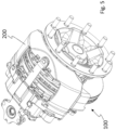
- Fig. 5 illustrates a calliper 200 provided to control the activation of the brake pads 110 in the brake system 100 of Fig. 4 .
- Fig. 6 is a cross-sectional detailed view of the calliper 200 and brake system 100 in Fig. 5 .
- the calliper 200 may be a conventional calliper for controlling the movement of the brake pads 110.
- the calliper 200 has a pump arrangement 202.
- hydraulic fluid in the pump arrangement 202 will cause the brake pads 110 to slide upwardly along the inclined interface 204 formed by the mating sliding portions of the brake pads 110 and of the carrier 140, respectively, and will cause the respective friction surface of the brake pads 110 to be pressed against the brake disc 102.
- the brake disc 102 By squeezing the brake disc 102 between the brake pads 110, the produced friction will reduce the rotational speed of the brake disc 102, and thereby reducing the speed of the vehicle.
- the inclined interface 204 (comprising the first sliding portions of the brake pads 110 and the second sliding portions of the carrier 140) will, due to gravitational force, and any vibrations (and optionally due to a downwardly pressing spring element) urge the brake pads 110 in an opposite direction. That is, the brake pads 110 will move downwardly along the inclined interface 204 and away from the brake disc 102, thereby reducing the risk of drag.
- Fig. 7 illustrates schematically a side-view of a brake pad 210 in accordance with at least another exemplary embodiment of the invention.
- the brake pad 210 has a friction surface 16 and an opposite surface 18.
- the brake pad 210 has a sliding portion 220 having a curved extension (like an arc of a circle) from the friction surface 16 to the opposite surface 18.
- the sliding portion 220 may, however, in other embodiments extend a shorter distance, and may have a different curved form.
- a line contact is achievable between the sliding portion 220 and a mating sliding portion of the carrier, if the mating sliding portion has a different form, for instance, non-curved. This facilitates the retraction of the brake pad after the brake is released by the driver, due to the low line contact friction between the sliding portions.
- Fig. 7 have only been illustrated very schematically to show the principle of using a curved sliding portion. It should, however, be understood that the brake pad may have various other features, such as those described elsewhere in this application.
- the brake pad 210 may comprise a backing part and a consumable lining part, wherein the sliding portion is formed by both or only one of said parts.
- the brake pad 210 may have two or more sliding portions spaced apart from each other, and any other compatible feature already described in this disclosure.
- Figs. 8a-8b illustrate a brake pad 310 in accordance with at least a further exemplary embodiment of the invention.
- Fig. 8a is a side view of the brake pad 310
- Fig. 8b is a perspective view of the brake pad 310.
- the brake pad 310 is configured for use in a calliper which, compared to the position of the calliper in Fig. 5 is displaced 90° along the circumference of the brake disc, i.e. at a position corresponding to "3 o'clock" or "9 o'clock".
- the brake pad 310 of Figs. 8a-8b comprises a friction surface 16 and an opposite surface 18.
- the upper side 312 and the lower side 314 have shorter extensions than in the other drawing figures since this brake pad 310 is intended to be placed at a different position around the brake disc.
- the brake pad 310 comprises a longer lateral side 315 extending in one direction from the upper side 312 to the lower side 314 and extending in another direction from the friction surface 16 to the opposite surface 18, wherein the lateral side 315 is adapted to face in a direction towards said geometrical centre axis.
- the lower side 314 of the brake pad 310 comprises a sliding portion 320 (here illustrated as a straight sliding portion, however, in other embodiments it may be curved) which extends downwards towards the opposite surface 18.
- the sliding portion 320 is configured to slide against a mating sliding portion of a carrier, and the downwards extension of the sliding portion 320 will in combination with gravitational force and possibly vibrational forces cause the brake pad to be retracted from the brake disc, when the driver has released the brake pedal.
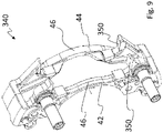
- Fig. 9 illustrates a carrier 340 for use in a brake arrangement in accordance with at least another exemplary embodiment of the invention.
- the carrier 340 may suitably be used for receive a brake pad 310 according to Figs. 8a-8b and, thus for mounting with a calliper laterally (instead of on top of the brake disc), as explained previously.
- the carrier 340 has receiving sliding portions, second sliding portions 350, for receiving the sliding portions of two brake pads.
- the carrier 340 of Fig. 9 has an inner part 42 and an outer part 44, both of which comprise a respective arched portion 46.
- the second sliding portions 350 extend substantially perpendicularly to the arched portions 46.
- the second sliding portions 350 taper downwardly away from the brake disc, and may suitably have the same angle of taper as the sliding portions of the brake pad to be received, such as the brake pad 310 of Figs. 8a-8b .
- a brake pad may be configured as a hybrid between the brake pad of Figs. 2a-2c and the brake pad of Fig. 8a-8b .
- a lateral side of the brake pad such as the brake pad of Figs. 8a-8b , may be provided with additional sliding portions.
- additional sliding portions would also be provided with a taper getting closer to the geometrical centre axis of the brake disc as the additional sliding portion extends towards the opposite surface.
- such a hybrid embodiment could be used in connection with a carrier and a calliper position as illustrated in Figs. 3-5 , or in connection with a carrier as illustrated in Fig. 9 and a 90° displaced calliper position.
Landscapes
- Engineering & Computer Science (AREA)
- General Engineering & Computer Science (AREA)
- Mechanical Engineering (AREA)
- Braking Arrangements (AREA)
Claims (16)
- Plaquette de frein (10, 110, 210, 310) pour un véhicule (2), adaptée pour être reliée à un support (40, 140) autour d'un disque de frein rotatif (102) qui tourne autour d'un axe central géométrique, la plaquette de frein (10, 110, 210, 310) comprenant :un côté supérieur (12, 312),un côté inférieur (14, 314),une surface de frottement (16) s'étendant vers le bas depuis le côté supérieur (12) jusqu'au côté inférieur (14) et étant adaptée pour être pressée contre un disque de frein (102),une surface opposée (18) s'étendant vers le bas depuis le côté supérieur (12) jusqu'au côté inférieur (14) et étant adaptée pour être orientée à l'écart du disque de frein (102),caractérisée en ce que le côté inférieur (14) comprend au moins une partie coulissante (20, 220 320) configurée pour coulisser contre une partie coulissante conjuguée (50, 350) d'un support (40, 140, 340), l'au moins une partie coulissante (20, 220, 320) s'étendant vers le bas vers la surface opposée (18).
- Plaquette de frein (10, 110, 310) selon la revendication 1, dans laquelle l'au moins une partie coulissante (20, 320) s'étend obliquement vers le bas en direction de la surface opposée (18).
- Plaquette de frein (210) selon la revendication 1, dans laquelle l'au moins une partie coulissante (220) s'étend dans une courbure vers le bas en direction de la surface opposée (18).
- Plaquette de frein (10, 110, 210, 310) selon l'une quelconque des revendications 1 à 3, comprenant une partie de support (22) et une partie de revêtement consommable (24) montée de manière fixe sur la partie de support (22), dans laquelle la surface de frottement (16) est prévue sur la partie de revêtement (24) et la surface opposée (18) est prévue sur la partie de support (22), dans laquelle la partie coulissante s'étendant vers le bas (20, 220, 320) est formée à la fois par la partie de support (22) et la partie de revêtement (24).
- Plaquette de frein (10, 110, 210, 310) selon l'une quelconque des revendications 1 à 4, dans laquelle l'au moins une partie coulissante (20, 220, 320) s'étend de la surface de frottement (16) à la surface opposée (18), interconnectant ainsi la surface de frottement (16) à la surface opposée (18).
- Plaquette de frein (10, 110) selon la revendication 2 ou l'une quelconque des revendications 4 à 5 lorsqu'elles dépendent de la revendication 2, dans laquelle la surface de frottement (16) s'étend dans un plan géométrique, dans laquelle l'au moins une partie coulissante (20) s'étend selon un angle (α) de 3° à 45°, tel que de 5° à 30°, par exemple de 7° à 15° par rapport à une normale audit plan géométrique.
- Plaquette de frein (10, 110, 210) selon l'une quelconque des revendications 1 à 6, comprenant au moins deux parties coulissantes (20, 220) espacées l'une de l'autre.
- Plaquette de frein (10, 110, 210) selon la revendication 7, dans laquelle lesdites deux parties coulissantes (20) sont situées sur des côtés respectifs d'un plan de symétrie de la plaquette de frein (10, 110, 210).
- Plaquette de frein (10, 110, 210) selon l'une quelconque des revendications 1 à 8, dans laquelle le côté supérieur (12) est adapté pour faire face à l'écart d'un axe central géométrique d'un disque de frein (102), dans laquelle le côté inférieur (14) est adapté pour faire face dans une direction vers ledit axe central géométrique, dans laquelle la surface de frottement (16) est adaptée pour être pressée contre le disque de frein au-dessus dudit axe central géométrique.
- Plaquette de frein (310) selon l'une quelconque des revendications 1 à 8, comprenant un côté latéral (315) s'étendant dans une direction depuis le côté supérieur (312) jusqu'au côté inférieur (314) et s'étendant dans une autre direction depuis la surface de frottement (16) jusqu'à la surface opposée (18), dans laquelle le côté latéral (315) est adapté pour faire face dans une direction vers ledit axe central géométrique.
- Agencement de frein (104) comprenant une plaquette de frein (10, 110, 210, 310) selon l'une quelconque des revendications 1 à 10, et un support (40, 140, 340) adapté pour être monté sur un disque de frein rotatif (102), dans lequel la partie coulissante (20, 220, 320) de la plaquette de frein (10, 110) est une première partie coulissante (20, 220, 320), dans lequel le support comprend une deuxième partie coulissante (50, 350) s'accouplant avec la première partie coulissante (20, 220, 320), dans lequel la plaquette de frein (10, 110) avec la première partie coulissante (20, 220, 320) est activée pour coulisser le long de la deuxième partie coulissante (50, 350) vers et à l'écart du disque de frein (102).
- Agencement de frein (104) selon la revendication 11 lorsqu'elle dépend directement ou indirectement de la revendication 2, dans lequel la deuxième partie coulissante (50, 350) et la première partie coulissante (120, 320) ont le même angle d'inclinaison par rapport à la surface de frottement (16) de la plaquette de frein (10, 110, 310).
- Agencement de frein (104) selon l'une quelconque des revendications 11 à 12, comprenant en outre un élément de ressort (28, 128) poussant la première partie coulissante (20, 220) contre la deuxième partie coulissante (50) par une force de ressort dirigée vers le bas.
- Système de frein (100) comprenant un agencement de frein (104) selon l'une quelconque des revendications 11 à 13 et un disque de frein (102) qui peut tourner autour d'un axe central géométrique, dans lequel le support (40, 140, 340) est monté de manière à permettre à la surface de frottement (16) de la plaquette de frein (10, 110, 210, 310) d'être pressée contre le disque de frein (102) lorsque la plaquette de frein (10, 110, 210, 310) est soumise à une force dirigée vers le disque de frein (102).
- Système de frein (100) selon la revendication 14, dans lequel la première partie coulissante (20, 220, 320) et la deuxième partie coulissante (50, 350) s'effilent vers le bas, comme vers l'axe central géométrique vu dans une direction s'éloignant du disque de frein (102), dans lequel l'effilement permet à la plaquette de frein (10, 110, 210, 310) de s'éloigner du disque de frein (102) en raison de vibrations et / ou de gravité.
- Véhicule comprenant une plaquette de frein (10, 110, 210, 310) selon l'une quelconque des revendications 1 à 10, un agencement de frein (104) selon l'une quelconque des revendications 11 à 13, ou un système de frein (100) selon l'une quelconque des revendications 14 à 15.
Applications Claiming Priority (1)
| Application Number | Priority Date | Filing Date | Title |
|---|---|---|---|
| PCT/EP2019/059527 WO2020207601A1 (fr) | 2019-04-12 | 2019-04-12 | Plaquette de frein pour un véhicule, agencement de frein, système de freinage et véhicule |
Publications (2)
| Publication Number | Publication Date |
|---|---|
| EP3953600A1 EP3953600A1 (fr) | 2022-02-16 |
| EP3953600B1 true EP3953600B1 (fr) | 2023-02-15 |
Family
ID=66286312
Family Applications (1)
| Application Number | Title | Priority Date | Filing Date |
|---|---|---|---|
| EP19719450.9A Active EP3953600B1 (fr) | 2019-04-12 | 2019-04-12 | Plaquette de frein pour un véhicule, agencement de frein, système de freinage et véhicule |
Country Status (4)
| Country | Link |
|---|---|
| US (1) | US12117054B2 (fr) |
| EP (1) | EP3953600B1 (fr) |
| CN (1) | CN113710918B (fr) |
| WO (1) | WO2020207601A1 (fr) |
Families Citing this family (1)
| Publication number | Priority date | Publication date | Assignee | Title |
|---|---|---|---|---|
| DE102023110198A1 (de) | 2023-04-21 | 2024-10-24 | Bpw Bergische Achsen Kommanditgesellschaft | Bremspad und Scheibenbremse |
Family Cites Families (18)
| Publication number | Priority date | Publication date | Assignee | Title |
|---|---|---|---|---|
| GB1041217A (en) * | 1962-07-10 | 1966-09-01 | Dunlop Rubber Co | Improvements in disc brakes |
| FR2071083A5 (fr) | 1969-12-17 | 1971-09-17 | Dba | |
| GB1333599A (en) * | 1970-05-29 | 1973-10-10 | Girling Ltd | Disc brakes for vehicles |
| AU540891B2 (en) * | 1980-02-26 | 1984-12-06 | Barker Brettell & Duncan | Sliding caliper disc brakes |
| US5467847A (en) * | 1993-09-02 | 1995-11-21 | Perrot Bremsen Gmbh | Disc brake |
| KR100471914B1 (ko) | 1999-04-30 | 2005-03-08 | 델피 테크놀로지스 인코포레이티드 | 미끄럼식 브레이크 디스크를 구비한 디스크 브레이크 |
| WO2002086344A1 (fr) | 2001-04-20 | 2002-10-31 | Freni Brembo S.P.A. | Fixation de plaquette de frein pour freins a disque |
| JP4732256B2 (ja) | 2006-06-26 | 2011-07-27 | 曙ブレーキ工業株式会社 | ディスクブレーキ用パッドクリップ |
| US20080067020A1 (en) | 2006-09-14 | 2008-03-20 | Akebono Corporation (North America) | Shoe to machined cast anchor interface for duo-servo drum brake |
| DE102008013268A1 (de) | 2007-10-09 | 2009-04-16 | Continental Engineering Services Gmbh | Bremsbelag für eine Teilbelag-Scheibenbremse |
| WO2015050638A1 (fr) | 2013-10-02 | 2015-04-09 | Bendix Spicer Foundation Brake Llc | Système et procédé de montage et de maintien de plaquette de frein à disque |
| CN106460975B (zh) | 2014-04-08 | 2019-06-18 | 福乐尼·乐姆宝公开有限公司 | 盘式制动衬块、用于盘式制动卡钳的弹簧以及盘式制动卡钳总成 |
| DE102015122585A1 (de) | 2015-12-22 | 2017-06-22 | Bpw Bergische Achsen Kg | Bremsbelaghalterung einer Fahrzeug-Scheibenbremse, Bremsbelag, Bügel einer Bremsbelaghalterung |
| IT201600128163A1 (it) * | 2016-12-19 | 2018-06-19 | Freni Brembo Spa | Pinza freno |
| IT201700013292A1 (it) | 2017-02-07 | 2018-08-07 | Campagnolo Srl | Pastiglia per freno a disco di bicicletta |
| CN109281961B (zh) | 2017-07-21 | 2021-03-12 | 英国美瑞特重型车制动系统有限公司 | 盘式制动器 |
| WO2021043384A1 (fr) * | 2019-09-02 | 2021-03-11 | Volvo Truck Corporation | Ensemble de retenue de plaquette de frein |
| US12234871B2 (en) * | 2020-02-20 | 2025-02-25 | Volvo Truck Corporation | Brake pad retainer system, brake pad, and vehicle |
-
2019
- 2019-04-12 EP EP19719450.9A patent/EP3953600B1/fr active Active
- 2019-04-12 CN CN201980095197.2A patent/CN113710918B/zh active Active
- 2019-04-12 US US17/601,518 patent/US12117054B2/en active Active
- 2019-04-12 WO PCT/EP2019/059527 patent/WO2020207601A1/fr not_active Ceased
Also Published As
| Publication number | Publication date |
|---|---|
| EP3953600A1 (fr) | 2022-02-16 |
| CN113710918A (zh) | 2021-11-26 |
| WO2020207601A1 (fr) | 2020-10-15 |
| US20220163079A1 (en) | 2022-05-26 |
| US12117054B2 (en) | 2024-10-15 |
| CN113710918B (zh) | 2024-12-17 |
Similar Documents
| Publication | Publication Date | Title |
|---|---|---|
| CN104105899B (zh) | 一种用于鼓式刹车装置的刹车片 | |
| CN113195922B (zh) | 盘式制动器卡钳本体的衬垫回位弹簧和盘式制动器卡钳 | |
| EP2748482A2 (fr) | Corps d'étrier pour frein à disque | |
| KR20140134274A (ko) | 자동차 디스크 브레이크의 패드 구속 시스템 | |
| EP3953600B1 (fr) | Plaquette de frein pour un véhicule, agencement de frein, système de freinage et véhicule | |
| CN112654798A (zh) | 盘式制动器卡钳本体 | |
| JPH09257063A (ja) | 車両用ディスクブレーキ | |
| US6851524B2 (en) | Disc brake for motor vehicles | |
| RU2628555C2 (ru) | Тормозная колодка для барабанного тормоза и узел тормоза | |
| EP3899305B1 (fr) | Corps d'étrier et étrier de freinage avec un tel corps d'étrier | |
| US12253132B2 (en) | Caliper body for a brake caliper | |
| JP7384744B2 (ja) | 対向ピストン型ディスクブレーキ用キャリパ | |
| JP2006275230A (ja) | 鉄道車両用のブレーキライニング及びディスクブレーキ | |
| WO1998055778A1 (fr) | Ameliorations concernant les assemblages de semelle et de revetement de freins a disques | |
| JP2007155107A (ja) | 鉄道車両用ブレーキライニング及びディスクブレーキ | |
| JPH09329162A (ja) | ディスクブレーキ装置 | |
| JP2007051729A (ja) | 車両用ディスクブレーキのキャリパボディ | |
| US20250129829A1 (en) | Pad clip for disc brake device and disc brake device | |
| JP2012167739A (ja) | ディスクブレーキ | |
| CN110446876A (zh) | 磨损优化的垫设计 | |
| JPS6319630Y2 (fr) | ||
| JPH10267054A (ja) | パーキング用ドラムブレーキ付きディスクブレーキ | |
| JP2011007338A (ja) | 車両用ディスクブレーキ | |
| JP2005249006A (ja) | ディスクブレーキ | |
| US20140008963A1 (en) | Rim rotor braking system |
Legal Events
| Date | Code | Title | Description |
|---|---|---|---|
| STAA | Information on the status of an ep patent application or granted ep patent |
Free format text: STATUS: UNKNOWN |
|
| STAA | Information on the status of an ep patent application or granted ep patent |
Free format text: STATUS: THE INTERNATIONAL PUBLICATION HAS BEEN MADE |
|
| PUAI | Public reference made under article 153(3) epc to a published international application that has entered the european phase |
Free format text: ORIGINAL CODE: 0009012 |
|
| STAA | Information on the status of an ep patent application or granted ep patent |
Free format text: STATUS: REQUEST FOR EXAMINATION WAS MADE |
|
| 17P | Request for examination filed |
Effective date: 20211110 |
|
| AK | Designated contracting states |
Kind code of ref document: A1 Designated state(s): AL AT BE BG CH CY CZ DE DK EE ES FI FR GB GR HR HU IE IS IT LI LT LU LV MC MK MT NL NO PL PT RO RS SE SI SK SM TR |
|
| DAV | Request for validation of the european patent (deleted) | ||
| DAX | Request for extension of the european patent (deleted) | ||
| GRAP | Despatch of communication of intention to grant a patent |
Free format text: ORIGINAL CODE: EPIDOSNIGR1 |
|
| STAA | Information on the status of an ep patent application or granted ep patent |
Free format text: STATUS: GRANT OF PATENT IS INTENDED |
|
| INTG | Intention to grant announced |
Effective date: 20221021 |
|
| GRAS | Grant fee paid |
Free format text: ORIGINAL CODE: EPIDOSNIGR3 |
|
| GRAA | (expected) grant |
Free format text: ORIGINAL CODE: 0009210 |
|
| STAA | Information on the status of an ep patent application or granted ep patent |
Free format text: STATUS: THE PATENT HAS BEEN GRANTED |
|
| AK | Designated contracting states |
Kind code of ref document: B1 Designated state(s): AL AT BE BG CH CY CZ DE DK EE ES FI FR GB GR HR HU IE IS IT LI LT LU LV MC MK MT NL NO PL PT RO RS SE SI SK SM TR |
|
| REG | Reference to a national code |
Ref country code: CH Ref legal event code: EP Ref country code: GB Ref legal event code: FG4D |
|
| REG | Reference to a national code |
Ref country code: DE Ref legal event code: R096 Ref document number: 602019025280 Country of ref document: DE |
|
| REG | Reference to a national code |
Ref country code: AT Ref legal event code: REF Ref document number: 1548377 Country of ref document: AT Kind code of ref document: T Effective date: 20230315 Ref country code: IE Ref legal event code: FG4D |
|
| REG | Reference to a national code |
Ref country code: NL Ref legal event code: FP |
|
| REG | Reference to a national code |
Ref country code: LT Ref legal event code: MG9D |
|
| REG | Reference to a national code |
Ref country code: AT Ref legal event code: MK05 Ref document number: 1548377 Country of ref document: AT Kind code of ref document: T Effective date: 20230215 |
|
| PG25 | Lapsed in a contracting state [announced via postgrant information from national office to epo] |
Ref country code: RS Free format text: LAPSE BECAUSE OF FAILURE TO SUBMIT A TRANSLATION OF THE DESCRIPTION OR TO PAY THE FEE WITHIN THE PRESCRIBED TIME-LIMIT Effective date: 20230215 Ref country code: PT Free format text: LAPSE BECAUSE OF FAILURE TO SUBMIT A TRANSLATION OF THE DESCRIPTION OR TO PAY THE FEE WITHIN THE PRESCRIBED TIME-LIMIT Effective date: 20230615 Ref country code: NO Free format text: LAPSE BECAUSE OF FAILURE TO SUBMIT A TRANSLATION OF THE DESCRIPTION OR TO PAY THE FEE WITHIN THE PRESCRIBED TIME-LIMIT Effective date: 20230515 Ref country code: LV Free format text: LAPSE BECAUSE OF FAILURE TO SUBMIT A TRANSLATION OF THE DESCRIPTION OR TO PAY THE FEE WITHIN THE PRESCRIBED TIME-LIMIT Effective date: 20230215 Ref country code: LT Free format text: LAPSE BECAUSE OF FAILURE TO SUBMIT A TRANSLATION OF THE DESCRIPTION OR TO PAY THE FEE WITHIN THE PRESCRIBED TIME-LIMIT Effective date: 20230215 Ref country code: HR Free format text: LAPSE BECAUSE OF FAILURE TO SUBMIT A TRANSLATION OF THE DESCRIPTION OR TO PAY THE FEE WITHIN THE PRESCRIBED TIME-LIMIT Effective date: 20230215 Ref country code: ES Free format text: LAPSE BECAUSE OF FAILURE TO SUBMIT A TRANSLATION OF THE DESCRIPTION OR TO PAY THE FEE WITHIN THE PRESCRIBED TIME-LIMIT Effective date: 20230215 Ref country code: AT Free format text: LAPSE BECAUSE OF FAILURE TO SUBMIT A TRANSLATION OF THE DESCRIPTION OR TO PAY THE FEE WITHIN THE PRESCRIBED TIME-LIMIT Effective date: 20230215 |
|
| PG25 | Lapsed in a contracting state [announced via postgrant information from national office to epo] |
Ref country code: SE Free format text: LAPSE BECAUSE OF FAILURE TO SUBMIT A TRANSLATION OF THE DESCRIPTION OR TO PAY THE FEE WITHIN THE PRESCRIBED TIME-LIMIT Effective date: 20230215 Ref country code: PL Free format text: LAPSE BECAUSE OF FAILURE TO SUBMIT A TRANSLATION OF THE DESCRIPTION OR TO PAY THE FEE WITHIN THE PRESCRIBED TIME-LIMIT Effective date: 20230215 Ref country code: IS Free format text: LAPSE BECAUSE OF FAILURE TO SUBMIT A TRANSLATION OF THE DESCRIPTION OR TO PAY THE FEE WITHIN THE PRESCRIBED TIME-LIMIT Effective date: 20230615 Ref country code: GR Free format text: LAPSE BECAUSE OF FAILURE TO SUBMIT A TRANSLATION OF THE DESCRIPTION OR TO PAY THE FEE WITHIN THE PRESCRIBED TIME-LIMIT Effective date: 20230516 Ref country code: FI Free format text: LAPSE BECAUSE OF FAILURE TO SUBMIT A TRANSLATION OF THE DESCRIPTION OR TO PAY THE FEE WITHIN THE PRESCRIBED TIME-LIMIT Effective date: 20230215 |
|
| PG25 | Lapsed in a contracting state [announced via postgrant information from national office to epo] |
Ref country code: SM Free format text: LAPSE BECAUSE OF FAILURE TO SUBMIT A TRANSLATION OF THE DESCRIPTION OR TO PAY THE FEE WITHIN THE PRESCRIBED TIME-LIMIT Effective date: 20230215 Ref country code: RO Free format text: LAPSE BECAUSE OF FAILURE TO SUBMIT A TRANSLATION OF THE DESCRIPTION OR TO PAY THE FEE WITHIN THE PRESCRIBED TIME-LIMIT Effective date: 20230215 Ref country code: EE Free format text: LAPSE BECAUSE OF FAILURE TO SUBMIT A TRANSLATION OF THE DESCRIPTION OR TO PAY THE FEE WITHIN THE PRESCRIBED TIME-LIMIT Effective date: 20230215 Ref country code: DK Free format text: LAPSE BECAUSE OF FAILURE TO SUBMIT A TRANSLATION OF THE DESCRIPTION OR TO PAY THE FEE WITHIN THE PRESCRIBED TIME-LIMIT Effective date: 20230215 Ref country code: CZ Free format text: LAPSE BECAUSE OF FAILURE TO SUBMIT A TRANSLATION OF THE DESCRIPTION OR TO PAY THE FEE WITHIN THE PRESCRIBED TIME-LIMIT Effective date: 20230215 |
|
| REG | Reference to a national code |
Ref country code: DE Ref legal event code: R097 Ref document number: 602019025280 Country of ref document: DE |
|
| PG25 | Lapsed in a contracting state [announced via postgrant information from national office to epo] |
Ref country code: SK Free format text: LAPSE BECAUSE OF FAILURE TO SUBMIT A TRANSLATION OF THE DESCRIPTION OR TO PAY THE FEE WITHIN THE PRESCRIBED TIME-LIMIT Effective date: 20230215 |
|
| REG | Reference to a national code |
Ref country code: CH Ref legal event code: PL |
|
| PLBE | No opposition filed within time limit |
Free format text: ORIGINAL CODE: 0009261 |
|
| STAA | Information on the status of an ep patent application or granted ep patent |
Free format text: STATUS: NO OPPOSITION FILED WITHIN TIME LIMIT |
|
| PG25 | Lapsed in a contracting state [announced via postgrant information from national office to epo] |
Ref country code: LU Free format text: LAPSE BECAUSE OF NON-PAYMENT OF DUE FEES Effective date: 20230412 |
|
| REG | Reference to a national code |
Ref country code: BE Ref legal event code: MM Effective date: 20230430 |
|
| PG25 | Lapsed in a contracting state [announced via postgrant information from national office to epo] |
Ref country code: MC Free format text: LAPSE BECAUSE OF FAILURE TO SUBMIT A TRANSLATION OF THE DESCRIPTION OR TO PAY THE FEE WITHIN THE PRESCRIBED TIME-LIMIT Effective date: 20230215 |
|
| 26N | No opposition filed |
Effective date: 20231116 |
|
| GBPC | Gb: european patent ceased through non-payment of renewal fee |
Effective date: 20230515 |
|
| PG25 | Lapsed in a contracting state [announced via postgrant information from national office to epo] |
Ref country code: SI Free format text: LAPSE BECAUSE OF FAILURE TO SUBMIT A TRANSLATION OF THE DESCRIPTION OR TO PAY THE FEE WITHIN THE PRESCRIBED TIME-LIMIT Effective date: 20230215 Ref country code: MC Free format text: LAPSE BECAUSE OF FAILURE TO SUBMIT A TRANSLATION OF THE DESCRIPTION OR TO PAY THE FEE WITHIN THE PRESCRIBED TIME-LIMIT Effective date: 20230215 Ref country code: LI Free format text: LAPSE BECAUSE OF NON-PAYMENT OF DUE FEES Effective date: 20230430 Ref country code: CH Free format text: LAPSE BECAUSE OF NON-PAYMENT OF DUE FEES Effective date: 20230430 |
|
| REG | Reference to a national code |
Ref country code: IE Ref legal event code: MM4A |
|
| PG25 | Lapsed in a contracting state [announced via postgrant information from national office to epo] |
Ref country code: BE Free format text: LAPSE BECAUSE OF NON-PAYMENT OF DUE FEES Effective date: 20230430 |
|
| PG25 | Lapsed in a contracting state [announced via postgrant information from national office to epo] |
Ref country code: IE Free format text: LAPSE BECAUSE OF NON-PAYMENT OF DUE FEES Effective date: 20230412 |
|
| PG25 | Lapsed in a contracting state [announced via postgrant information from national office to epo] |
Ref country code: IE Free format text: LAPSE BECAUSE OF NON-PAYMENT OF DUE FEES Effective date: 20230412 Ref country code: GB Free format text: LAPSE BECAUSE OF NON-PAYMENT OF DUE FEES Effective date: 20230515 |
|
| PG25 | Lapsed in a contracting state [announced via postgrant information from national office to epo] |
Ref country code: IT Free format text: LAPSE BECAUSE OF FAILURE TO SUBMIT A TRANSLATION OF THE DESCRIPTION OR TO PAY THE FEE WITHIN THE PRESCRIBED TIME-LIMIT Effective date: 20230215 |
|
| PG25 | Lapsed in a contracting state [announced via postgrant information from national office to epo] |
Ref country code: BG Free format text: LAPSE BECAUSE OF FAILURE TO SUBMIT A TRANSLATION OF THE DESCRIPTION OR TO PAY THE FEE WITHIN THE PRESCRIBED TIME-LIMIT Effective date: 20230215 |
|
| PG25 | Lapsed in a contracting state [announced via postgrant information from national office to epo] |
Ref country code: BG Free format text: LAPSE BECAUSE OF FAILURE TO SUBMIT A TRANSLATION OF THE DESCRIPTION OR TO PAY THE FEE WITHIN THE PRESCRIBED TIME-LIMIT Effective date: 20230215 |
|
| PGFP | Annual fee paid to national office [announced via postgrant information from national office to epo] |
Ref country code: NL Payment date: 20250424 Year of fee payment: 7 |
|
| PGFP | Annual fee paid to national office [announced via postgrant information from national office to epo] |
Ref country code: DE Payment date: 20250428 Year of fee payment: 7 |
|
| PGFP | Annual fee paid to national office [announced via postgrant information from national office to epo] |
Ref country code: FR Payment date: 20250424 Year of fee payment: 7 |
|
| PG25 | Lapsed in a contracting state [announced via postgrant information from national office to epo] |
Ref country code: CY Free format text: LAPSE BECAUSE OF FAILURE TO SUBMIT A TRANSLATION OF THE DESCRIPTION OR TO PAY THE FEE WITHIN THE PRESCRIBED TIME-LIMIT; INVALID AB INITIO Effective date: 20190412 |
|
| PG25 | Lapsed in a contracting state [announced via postgrant information from national office to epo] |
Ref country code: HU Free format text: LAPSE BECAUSE OF FAILURE TO SUBMIT A TRANSLATION OF THE DESCRIPTION OR TO PAY THE FEE WITHIN THE PRESCRIBED TIME-LIMIT; INVALID AB INITIO Effective date: 20190412 |
|
| PG25 | Lapsed in a contracting state [announced via postgrant information from national office to epo] |
Ref country code: TR Free format text: LAPSE BECAUSE OF FAILURE TO SUBMIT A TRANSLATION OF THE DESCRIPTION OR TO PAY THE FEE WITHIN THE PRESCRIBED TIME-LIMIT Effective date: 20230215 |