EP3953778B1 - Commande de dispositifs automatisés de déplacement de palettes - Google Patents
Commande de dispositifs automatisés de déplacement de palettes Download PDFInfo
- Publication number
- EP3953778B1 EP3953778B1 EP20788441.2A EP20788441A EP3953778B1 EP 3953778 B1 EP3953778 B1 EP 3953778B1 EP 20788441 A EP20788441 A EP 20788441A EP 3953778 B1 EP3953778 B1 EP 3953778B1
- Authority
- EP
- European Patent Office
- Prior art keywords
- pallet
- automated
- lane
- looping
- control algorithm
- Prior art date
- Legal status (The legal status is an assumption and is not a legal conclusion. Google has not performed a legal analysis and makes no representation as to the accuracy of the status listed.)
- Active
Links
Images






Classifications
-
- B—PERFORMING OPERATIONS; TRANSPORTING
- B65—CONVEYING; PACKING; STORING; HANDLING THIN OR FILAMENTARY MATERIAL
- B65G—TRANSPORT OR STORAGE DEVICES, e.g. CONVEYORS FOR LOADING OR TIPPING, SHOP CONVEYOR SYSTEMS OR PNEUMATIC TUBE CONVEYORS
- B65G1/00—Storing articles, individually or in orderly arrangement, in warehouses or magazines
- B65G1/02—Storage devices
- B65G1/04—Storage devices mechanical
- B65G1/137—Storage devices mechanical with arrangements or automatic control means for selecting which articles are to be removed
- B65G1/1373—Storage devices mechanical with arrangements or automatic control means for selecting which articles are to be removed for fulfilling orders in warehouses
- B65G1/1375—Storage devices mechanical with arrangements or automatic control means for selecting which articles are to be removed for fulfilling orders in warehouses the orders being assembled on a commissioning stacker-crane or truck
-
- B—PERFORMING OPERATIONS; TRANSPORTING
- B65—CONVEYING; PACKING; STORING; HANDLING THIN OR FILAMENTARY MATERIAL
- B65G—TRANSPORT OR STORAGE DEVICES, e.g. CONVEYORS FOR LOADING OR TIPPING, SHOP CONVEYOR SYSTEMS OR PNEUMATIC TUBE CONVEYORS
- B65G1/00—Storing articles, individually or in orderly arrangement, in warehouses or magazines
- B65G1/02—Storage devices
- B65G1/04—Storage devices mechanical
- B65G1/0485—Check-in, check-out devices
-
- B—PERFORMING OPERATIONS; TRANSPORTING
- B65—CONVEYING; PACKING; STORING; HANDLING THIN OR FILAMENTARY MATERIAL
- B65G—TRANSPORT OR STORAGE DEVICES, e.g. CONVEYORS FOR LOADING OR TIPPING, SHOP CONVEYOR SYSTEMS OR PNEUMATIC TUBE CONVEYORS
- B65G1/00—Storing articles, individually or in orderly arrangement, in warehouses or magazines
- B65G1/02—Storage devices
- B65G1/04—Storage devices mechanical
- B65G1/0492—Storage devices mechanical with cars adapted to travel in storage aisles
-
- B—PERFORMING OPERATIONS; TRANSPORTING
- B65—CONVEYING; PACKING; STORING; HANDLING THIN OR FILAMENTARY MATERIAL
- B65G—TRANSPORT OR STORAGE DEVICES, e.g. CONVEYORS FOR LOADING OR TIPPING, SHOP CONVEYOR SYSTEMS OR PNEUMATIC TUBE CONVEYORS
- B65G1/00—Storing articles, individually or in orderly arrangement, in warehouses or magazines
- B65G1/02—Storage devices
- B65G1/04—Storage devices mechanical
- B65G1/137—Storage devices mechanical with arrangements or automatic control means for selecting which articles are to be removed
- B65G1/1373—Storage devices mechanical with arrangements or automatic control means for selecting which articles are to be removed for fulfilling orders in warehouses
-
- B—PERFORMING OPERATIONS; TRANSPORTING
- B65—CONVEYING; PACKING; STORING; HANDLING THIN OR FILAMENTARY MATERIAL
- B65G—TRANSPORT OR STORAGE DEVICES, e.g. CONVEYORS FOR LOADING OR TIPPING, SHOP CONVEYOR SYSTEMS OR PNEUMATIC TUBE CONVEYORS
- B65G1/00—Storing articles, individually or in orderly arrangement, in warehouses or magazines
- B65G1/02—Storage devices
- B65G1/04—Storage devices mechanical
- B65G1/137—Storage devices mechanical with arrangements or automatic control means for selecting which articles are to be removed
- B65G1/1373—Storage devices mechanical with arrangements or automatic control means for selecting which articles are to be removed for fulfilling orders in warehouses
- B65G1/1378—Storage devices mechanical with arrangements or automatic control means for selecting which articles are to be removed for fulfilling orders in warehouses the orders being assembled on fixed commissioning areas remote from the storage areas
-
- B—PERFORMING OPERATIONS; TRANSPORTING
- B65—CONVEYING; PACKING; STORING; HANDLING THIN OR FILAMENTARY MATERIAL
- B65G—TRANSPORT OR STORAGE DEVICES, e.g. CONVEYORS FOR LOADING OR TIPPING, SHOP CONVEYOR SYSTEMS OR PNEUMATIC TUBE CONVEYORS
- B65G61/00—Use of pick-up or transfer devices or of manipulators for stacking or de-stacking articles not otherwise provided for
-
- G—PHYSICS
- G01—MEASURING; TESTING
- G01C—MEASURING DISTANCES, LEVELS OR BEARINGS; SURVEYING; NAVIGATION; GYROSCOPIC INSTRUMENTS; PHOTOGRAMMETRY OR VIDEOGRAMMETRY
- G01C21/00—Navigation; Navigational instruments not provided for in groups G01C1/00 - G01C19/00
- G01C21/20—Instruments for performing navigational calculations
- G01C21/206—Instruments for performing navigational calculations specially adapted for indoor navigation
-
- G—PHYSICS
- G05—CONTROLLING; REGULATING
- G05B—CONTROL OR REGULATING SYSTEMS IN GENERAL; FUNCTIONAL ELEMENTS OF SUCH SYSTEMS; MONITORING OR TESTING ARRANGEMENTS FOR SUCH SYSTEMS OR ELEMENTS
- G05B13/00—Adaptive control systems, i.e. systems automatically adjusting themselves to have a performance which is optimum according to some preassigned criterion
- G05B13/02—Adaptive control systems, i.e. systems automatically adjusting themselves to have a performance which is optimum according to some preassigned criterion electric
- G05B13/0265—Adaptive control systems, i.e. systems automatically adjusting themselves to have a performance which is optimum according to some preassigned criterion electric the criterion being a learning criterion
-
- G—PHYSICS
- G05—CONTROLLING; REGULATING
- G05D—SYSTEMS FOR CONTROLLING OR REGULATING NON-ELECTRIC VARIABLES
- G05D1/00—Control of position, course, altitude or attitude of land, water, air or space vehicles, e.g. using automatic pilots
- G05D1/02—Control of position or course in two dimensions
- G05D1/021—Control of position or course in two dimensions specially adapted to land vehicles
- G05D1/0212—Control of position or course in two dimensions specially adapted to land vehicles with means for defining a desired trajectory
-
- G—PHYSICS
- G05—CONTROLLING; REGULATING
- G05D—SYSTEMS FOR CONTROLLING OR REGULATING NON-ELECTRIC VARIABLES
- G05D1/00—Control of position, course, altitude or attitude of land, water, air or space vehicles, e.g. using automatic pilots
- G05D1/02—Control of position or course in two dimensions
- G05D1/021—Control of position or course in two dimensions specially adapted to land vehicles
- G05D1/0231—Control of position or course in two dimensions specially adapted to land vehicles using optical position detecting means
- G05D1/0246—Control of position or course in two dimensions specially adapted to land vehicles using optical position detecting means using a video camera in combination with image processing means
- G05D1/0251—Control of position or course in two dimensions specially adapted to land vehicles using optical position detecting means using a video camera in combination with image processing means extracting 3D information from a plurality of images taken from different locations, e.g. stereo vision
-
- G—PHYSICS
- G05—CONTROLLING; REGULATING
- G05D—SYSTEMS FOR CONTROLLING OR REGULATING NON-ELECTRIC VARIABLES
- G05D1/00—Control of position, course, altitude or attitude of land, water, air or space vehicles, e.g. using automatic pilots
- G05D1/02—Control of position or course in two dimensions
- G05D1/021—Control of position or course in two dimensions specially adapted to land vehicles
- G05D1/0287—Control of position or course in two dimensions specially adapted to land vehicles involving a plurality of land vehicles, e.g. fleet or convoy travelling
-
- G—PHYSICS
- G05—CONTROLLING; REGULATING
- G05D—SYSTEMS FOR CONTROLLING OR REGULATING NON-ELECTRIC VARIABLES
- G05D1/00—Control of position, course, altitude or attitude of land, water, air or space vehicles, e.g. using automatic pilots
- G05D1/02—Control of position or course in two dimensions
- G05D1/021—Control of position or course in two dimensions specially adapted to land vehicles
- G05D1/0287—Control of position or course in two dimensions specially adapted to land vehicles involving a plurality of land vehicles, e.g. fleet or convoy travelling
- G05D1/0291—Fleet control
- G05D1/0297—Fleet control by controlling means in a control room
-
- G—PHYSICS
- G05—CONTROLLING; REGULATING
- G05D—SYSTEMS FOR CONTROLLING OR REGULATING NON-ELECTRIC VARIABLES
- G05D1/00—Control of position, course, altitude or attitude of land, water, air or space vehicles, e.g. using automatic pilots
- G05D1/20—Control system inputs
- G05D1/24—Arrangements for determining position or orientation
- G05D1/243—Means capturing signals occurring naturally from the environment, e.g. ambient optical, acoustic, gravitational or magnetic signals
- G05D1/2435—Extracting 3D information
-
- G—PHYSICS
- G05—CONTROLLING; REGULATING
- G05D—SYSTEMS FOR CONTROLLING OR REGULATING NON-ELECTRIC VARIABLES
- G05D1/00—Control of position, course, altitude or attitude of land, water, air or space vehicles, e.g. using automatic pilots
- G05D1/60—Intended control result
- G05D1/646—Following a predefined trajectory, e.g. a line marked on the floor or a flight path
-
- G—PHYSICS
- G05—CONTROLLING; REGULATING
- G05D—SYSTEMS FOR CONTROLLING OR REGULATING NON-ELECTRIC VARIABLES
- G05D1/00—Control of position, course, altitude or attitude of land, water, air or space vehicles, e.g. using automatic pilots
- G05D1/60—Intended control result
- G05D1/69—Coordinated control of the position or course of two or more vehicles
- G05D1/692—Coordinated control of the position or course of two or more vehicles involving a plurality of disparate vehicles
-
- G—PHYSICS
- G06—COMPUTING OR CALCULATING; COUNTING
- G06Q—INFORMATION AND COMMUNICATION TECHNOLOGY [ICT] SPECIALLY ADAPTED FOR ADMINISTRATIVE, COMMERCIAL, FINANCIAL, MANAGERIAL OR SUPERVISORY PURPOSES; SYSTEMS OR METHODS SPECIALLY ADAPTED FOR ADMINISTRATIVE, COMMERCIAL, FINANCIAL, MANAGERIAL OR SUPERVISORY PURPOSES, NOT OTHERWISE PROVIDED FOR
- G06Q10/00—Administration; Management
- G06Q10/08—Logistics, e.g. warehousing, loading or distribution; Inventory or stock management
-
- G—PHYSICS
- G06—COMPUTING OR CALCULATING; COUNTING
- G06Q—INFORMATION AND COMMUNICATION TECHNOLOGY [ICT] SPECIALLY ADAPTED FOR ADMINISTRATIVE, COMMERCIAL, FINANCIAL, MANAGERIAL OR SUPERVISORY PURPOSES; SYSTEMS OR METHODS SPECIALLY ADAPTED FOR ADMINISTRATIVE, COMMERCIAL, FINANCIAL, MANAGERIAL OR SUPERVISORY PURPOSES, NOT OTHERWISE PROVIDED FOR
- G06Q10/00—Administration; Management
- G06Q10/08—Logistics, e.g. warehousing, loading or distribution; Inventory or stock management
- G06Q10/087—Inventory or stock management, e.g. order filling, procurement or balancing against orders
Definitions
- This document generally describes technology for controlling operations of multiple automated pallet movers in a physical space.
- automated warehouse systems can automate storage and retrieval of goods and pallets in a warehouse.
- Pallets for example, can be flat transport structures that support goods in a stable manner and that are adapted to fit forklifts and/or other devices/machines to move the pallets.
- Automated warehouse systems can include conveyors designed for transporting goods and pallets to specific warehouse locations, and racking systems for storing and retrieving the goods and pallets.
- US 2008/131255 which comprises the features mentioned in the preamble of claim 1, discloses palletizing systems and methods.
- the systems and methods include a pallet building module for receiving customer orders and generating pallet building instructions for arranging the products on the pallets, among other functions.
- US 2018/300435 generally describes simulating warehouse automation designs and evaluating the results of such simulations to optimize automated warehouse designs.
- Warehouse automation can be simulated, for example, to determine an optimal warehouse automation design given a variety of parameters that are specific to the warehouse, such as the expected customer inventory demands over time, the layout of the warehouse, and/or the specific automation features that are possible within the warehouse.
- an automated warehouse system as set out in claim 1.
- a warehouse may include a pallet loading/unloading area where trucks are docked so that pallets can be unloaded from, or loaded to, the trucks.
- a warehouse may further include a pallet storage area configured to store pallets in a dense arrangement.
- the pallet storage area may include multiple-story racks with an elevator system operable to convey pallets to/from different floors of the racks.
- a conveyor belt system may be used to transport pallets between the pallet loading/unloading area and the pallet storage area.
- a conveyor belt system includes a complex layout of conveyor belts which has many connection points between the conveyor belts and many bottle neck areas where multiple conveyor belts are connected to one conveyor belt.
- the conveyor belt system operates to concurrently convey multiple pallets from different start locations to different end locations.
- the pallet loading/unloading area may include multiple decks from which pallets can be loaded to trucks, and to which pallets can be unloaded from trucks by workers.
- the pallet racks may have multiple columns and rows in multiple levels (heights) to/from which pallets can be transported using different elevators.
- Such a complex conveyor belt system often results in clogging when a large number of pallets are conveyed at the same time between different start locations and end locations. For example, pallets which travel deep in the conveyor belt system can be stuck with other pallets moving along long routes of conveyor belts. Moreover, once the conveyor belts are set up, they are less flexible in creating and modifying paths along which pallets can be carried.
- the pallet transportation system described herein uses automated guided vehicles (AGVs) that replace the complex installed conveyor belt system to move pallets in a warehouse.
- Automated guided vehicles can automatically navigate through the warehouse and can be capable of picking up, moving, and dropping off pallets at various locations in the warehouse.
- Algorithms can be configured to optimize operation of automated guided vehicles in the warehouse, and can be used to determine optimal routes of each automated guided vehicle from a start location to an end location.
- the algorithms can be configured to optimize or minimize the number of cross-overs of the routes taken by the automated guided vehicles.
- the algorithms can be configured to optimize the timing of operation of respective automated guided vehicles, thereby reducing the likelihood of collision between vehicles.
- the algorithms can be configured to optimize or maximize the speed of respective automated guided vehicles.
- the algorithms can be configured to optimize or minimize the time required to complete a particular project of moving pallets in a warehouse.
- multiple lanes can be defined (e.g., virtual and/or marked lanes), and the algorithms can be configured such that the automated guided vehicles move through the warehouse according rules that coordinate movement of the automated guided vehicles using the lanes.
- Multiple automated guided vehicles can concurrently transport pallets through the warehouse using the same lanes and control algorithm, each automated guided vehicle travelling on possibly different routes resulting from performance of the same control algorithm.
- the multiple defined lanes and corresponding control algorithm can be modified and/or replaced on the fly, and the automated guided vehicles can transport pallets using different lanes and a corresponding different control algorithm.
- Modifying and/or replacing the lanes and corresponding control algorithm can be done in response to changing warehouse conditions, such as currently available automated guided vehicles, and a current job list that specifies pallets to be transported within the warehouse (e.g., pallets to be received from trucks, pallets to be moved from one warehouse location to another warehouse location, and/or pallets to be retrieved from storage and loaded onto trucks).
- changing warehouse conditions such as currently available automated guided vehicles, and a current job list that specifies pallets to be transported within the warehouse (e.g., pallets to be received from trucks, pallets to be moved from one warehouse location to another warehouse location, and/or pallets to be retrieved from storage and loaded onto trucks).
- an automated warehouse system can include a plurality of automated pallet movers, a physical space in which the plurality of automated pallet movers are configured to operate, and a control system configured to provide commands to each of the plurality of automated pallet movers for operating in the physical space.
- the commands can include a pallet transportation command including a pallet identifier of a pallet to be transported by the automated pallet mover in the physical space, and a destination location to which the pallet is to be transported by the automated pallet mover.
- the commands can also include a control algorithm command that specifies a control algorithm for moving through the physical space.
- the automated pallet mover can be configured to transport the pallet to the destination location according to a route resulting from performance of the control algorithm, while one or more of the other automated pallet movers concurrently transport other pallets to other destination locations according to other routes resulting from performance of the same control algorithm.
- implementations of this aspect include corresponding methods, and include corresponding apparatus and computer programs recorded on one or more computer storage devices, each configured to perform the actions of the methods.
- a system of one or more computers can be configured to perform particular operations or actions by virtue of having software, firmware, hardware, or a combination of them installed on the system that in operation causes or cause the system to perform the actions.
- One or more computer programs can be configured to perform particular operations or actions by virtue of including instructions that, when executed by data processing apparatus, case the apparatuses to perform the actions.
- At least one of the automated pallet movers can be an automated guided vehicle. At least one of the automated pallet movers can include a forklift device. The pallet identifier can be associated with a location of the pallet in the physical space.
- the control system can provide, to each of the automated pallet movers, a second, different control algorithm command that specifies a second, different control algorithm for moving through the physical space.
- the control system is further configured to perform operations including: (i) for each of a plurality of different control algorithms, performing one or more simulations of transporting pallets in the physical space by the plurality of automated pallet movers using the control algorithm, (ii) comparing pallet throughput resulting from simulated use of each control algorithm, and (iii) selecting an optimal control algorithm, the optimal control algorithm corresponding to greatest pallet throughput.
- the control algorithm command provided by the control system specifies the optimal control algorithm.
- the route travelled by the pallet mover resulting from performance of the control algorithm can be determined in real time, in response to locations and movements of the other pallet movers in the physical space.
- the physical space can include a plurality of pallet handling locations, each pallet handling location being a location from which pallets are retrieved and/or to which pallets are transported. At least one pallet handling location can be at the end of a conveyor belt in the physical space. At least one pallet handling location can be a designated area on a floor of the physical space. The plurality of pallet handling locations can be arranged such that a first row of pallet handling locations are located along a first edge of the physical space, and a second row of pallet handling locations are located along a second edge of the physical space different from the first edge.
- the physical space can include a plurality of lanes between the first and second rows of pallet handling locations, the lanes being configured for use by the automated pallet movers to transport pallets between pallet handling locations according to routes resulting from performance of the control algorithm.
- the lanes can include virtual lanes and/or marked lanes.
- the control algorithm and a different control algorithm can each be associated with a different plurality of lanes.
- the plurality of lanes can include: (i) a looping slow lane located along the first row of pallet handling locations and the second row of pallet handling locations, (ii) a looping fast lane that loops in a same direction as the looping slow lane and is located inside of the looping slow lane, and (iii) a turning lane that is located inside of the looping fast lane.
- the plurality of lanes can include: (i) a looping slow lane located along the first row of pallet handling locations and the second row of pallet handling locations, (ii) a looping fast lane that loops in a same direction as the looping slow lane and is located inside of the looping slow lane, and (iii) a plurality of buffer lanes that are located inside of the looping fast lane.
- the plurality of lanes can include: (i) a first looping lane that loops in a clockwise direction along a portion of the first row of pallet handling locations and a portion of the second row of pallet handling locations, and (ii) a second looping lane that loops in a counterclockwise direction along a different portion of the first row of pallet handling locations and a different portion of the second row of pallet handling locations.
- the plurality of lanes can include: (i) an exterior looping lane that loops along the first row of pallet handling locations and the second row of pallet handling locations, and (ii) a plurality of interior looping lanes that loop in a same direction as the exterior looping lane, each interior looping lane looping within the exterior looping lane.
- the technologies described herein may provide one or more of the following advantages.
- the pallet transportation system described herein can replace conventional pallet transportation devices, such as conveyor belt systems, by automated guided vehicles to intelligently move pallets of goods between different locations in a warehouse, thereby optimizing routes and/or timing of pallet transportation, avoiding collision between different pallets being transported, reducing a transportation time, and reducing operational costs.
- the pallet transportation system can provide great flexibility in managing pallets in a warehouse because automated guided vehicles allow a large number of possible paths between a particular set of start and end locations, as opposed to a conveyor belt system that provides a limited number of possible routes between the start and end locations.
- the pallet transportation system can provide redundancy in route selection by allowing a large number of route options between particular start and end positions.
- An optimal route can be selected from such multiple route options to meet different criteria required in managing pallets in a warehouse. Further, using a control algorithm for operating each of the automated pallet movers according to defined lanes and rules for travelling in the lanes, the pallet transportation system can conserve processing resources, and increase a number of automated pallet movers operating in a pallet transportation area without increasing collisions. An optimal control algorithm for operating the automated pallet movers according to the defined lanes can be determined for current warehouse conditions (e.g., based on simulation results), optimizing throughput of product in the warehouse.
- FIG. 1A depicts an example system 100 for controlling automated pallet movers in a warehouse 102, such as a storage warehouse, a distribution center, a retail warehouse, a cold storage warehouse, an overseas warehouse, a packing warehouse, a railway warehouse, a canal warehouse, or another sort of warehouse or facility.
- the warehouse 102 includes a pallet storage area 103, which can include pallet storage racks 104 which can be arranged in rows and/or columns and configured to store pallets 110 in different levels.
- One or more elevators 106 and rack conveyor belts 108 may be used to elevate pallets 110 to different levels and move them into desired locations in the racks 104.
- the warehouse 102 further includes a pallet transportation area 120 in which the system 100 operates to automate and optimize transportation of pallets between the staging area 112 and the pallet storage area 103.
- the system 100 can include automated pallet movers 130 to transport pallets 110 in the pallet transportation area 120.
- the automated pallet movers 130 may be configured to automatically navigate between the staging area 112 and the pallet storage area 103, and may be capable of picking up, moving, and dropping off pallets.
- AGVs can be configured to learn which routes are the fastest and take optimal paths, even within unpredictable environments. Multiple AGVs can collaboratively interact with other AGVs. In some examples, AGVs do not require external infrastructure for navigation, making implementation hassle-free and highly scalable. AGVs can be configured to detect, avoid, and dynamically move around obstacles (including other AGVs) to continue to their destinations, reducing downtime. Parameters associated with AGVs can be customized to navigate through aisles, personnel zones, narrow corridors, and other regions.
- FIGS. 2A-B depict example systems to control operation of automated guided vehicles (AGVs) using stereoscopic vision.
- an example AGV 200 e.g., an automated pallet mover 130, shown in FIGS. 1A-B
- stereoscopic imaging devices 202 e.g., stereoscopic cameras mounted on a side (e.g., a front-facing side) of the AGV 200.
- the AGV 200 may include multiple stereoscopic imaging devices that are positioned on its sides, such as an additional stereoscopic imaging device positioned on an opposing side (e.g., a rear-facing side) of the AGV 200.
- the stereoscopic image data 232 can be generated by the AGV 200 and used to determine a precise location of the AGV 200 within a physical environment, such as a warehouse.
- An example system for making such location determination for the AGV 200 can include a central system 220 that contains a spatial model 222 of the environment (e.g., point cloud of the environment).
- the AGV 200 can transmit the stereoscopic image data 232 over one or more networks 230 (e.g., Wi-Fi) to the central system 220, which can generate spatial positioning of features (e.g., points) from the stereoscopic image data 232, compare that spatial positioning of features to the spatial model 222 to determine the location of the AGV 200, and then transmit the location information 238 back to the AGV 200 (or to other systems used to control operation of the AGV 200).
- the spatial model can be loaded onto the AGV 200 and those determinations can be made locally on the AGV 200.
- FIG. 2B another example AGV 210 (e.g., similar to AGVs 130, shown in FIGS. 1A-B ) is depicted.
- the stereoscopic imaging device 212 is positioned and extends above a top surface of the AGV 210.
- Such a positioning of the stereoscopic imaging device 212 can provide a higher vantage point (higher relative to the ground), which may be used to generate more spatial positioning features (e.g., points) that can be used to more accurately determine the location of the AGV 210 using the spatial model 222.
- the systems 100 can be configured to optimize operation of automated pallet movers 130 in the warehouse 102 using various algorithms.
- the various algorithms may be configured to calculate a plurality of possible routes 142 for each automated pallet mover from a start location to an end location, and to determine an optimal route among them.
- the algorithms can be configured to choose a shortest route for at least one of the automated pallet movers.
- the algorithms can be configured to minimize the number of cross-overs of the routes taken by multiple automated pallet movers, thereby reducing the likelihood of collision between automated pallet movers.
- the algorithms can be configured to optimize the timing of operation of respective automated pallet movers, thereby reducing the likelihood of collision between automated pallet movers. In addition or alternatively, the algorithms can be configured to maximize the speed of at least one of the automated pallet movers. In addition or alternatively, the algorithms can be configured to minimize the time required to complete a particular project of moving pallets in a warehouse.
- multiple lanes 144, 146 may be defined within the warehouse 102, and the various algorithms may include rules for operating the automated pallet movers using the lanes. For example, the algorithms can be used to coordinate operation of multiple pallet movers, each automated pallet mover concurrently transporting pallets through the warehouse according to routes that result from execution of the algorithm.
- pallet transportation area 120 may be partitioned into one or more zones, each zone possibly being associated with different algorithms for optimizing operation of automated pallet movers 130 and/or coordinating operation of the automated pallet movers.
- optimal routes 142 may be specifically determined for each of the automated pallet movers 130
- a general control algorithm may be used for coordinating movement of the automated pallet movers 130 according to the lanes 144, 146.
- the first zone may include lighter and/or more irregular traffic of the automated pallet movers 130, whereas in the second zone, heavier and/or more regular traffic of the automated pallet movers 130 may be present or anticipated (e.g., due to an incoming shipment of pallets to be stored in a common section of the pallet storage area 103, or an outgoing shipment of pallets to be transported by one of the trucks 114).
- each zone may be associated with a different general control algorithm.
- an entire pallet transportation area 120 may use route optimization algorithms for each automated pallet mover 130, or a single general control algorithm for all of the automated pallet movers 130.
- the example technique 300 can be performed by any of a variety of appropriate systems, such as the example systems depicted in FIGS. 1A-B .
- the technique 300 can be used to determine optimal routes to move pallets in a warehouse, such as routes between staging area 112 (e.g., pallet loading/unloading area) and pallet storage area 103 (e.g., pallet storage racks).
- staging area 112 e.g., pallet loading/unloading area
- pallet storage area 103 e.g., pallet storage racks.
- identification of the pallets to be moved, their current positioning, and their destination positioning can be determined.
- optimal routes are determined for moving pallets to their destination positions.
- optimal routes can be determined by identifying routes that provide minimum crossovers there between when the pallets are transported to their destination positions along those routes (320), by identifying fastest routes for moving pallets to their destination positions (322), by identifying shortest routes for moving pallets to their destination positions (324), and/or by identifying routes that result in fastest completion of a project of moving entire pallets in desired manner (326).
- timing sequences for the routes can be determined.
- routes and timing sequences can be adjusted in order to avoid collisions and to maintain a minimum threshold distance between the automated pallet movers.
- such adjusted routes and timings can then be provided for use to control operation of the automated pallet movers to execute on the determinations.
- determining a plurality of possible routes and determining an optimal routes for each of the automated pallet movers may be computationally expensive, and may become more complex as a number of automated pallet movers operating in a warehouse environment increases. As such, performing the example technique 300 may be appropriate when a number of automated pallet movers is below a threshold number and/or when suitable computing resources are available.
- the algorithms can be configured to employ various defined lanes in a physical space, and to define a common set of rules to be followed by each of the automated pallet movers for navigating through the space according to the lanes, from a start location to and end location.
- the lanes 144, 146 can include virtual and/or marked regions in the pallet transportation area 120 that are defined by one or more computing devices in a system for controlling automated pallet movers (e.g., computing device 140), and are associated with one or more movement rules that are to be followed by the automated pallet movers 130 that travel in the lanes (e.g., maximum speed, minimum speed, rate of acceleration/deceleration, direction of travel, right of way, etc.).
- Virtual lanes can be regions in the pallet transportation area 120 that are not physically marked, but can be logically identified by the automated pallet movers 130 using location sensors and digital maps.
- Marked lanes may be regions in the pallet transportation area 120 that are physically identifiable by the automated pallet movers 130 (e.g., painted lanes that can be detected using cameras, light-bounded lanes that can be detected using light sensors, metal lanes that can be detected using magnetic sensors, etc.).
- interactions between the automated pallet movers may be simplified, processing resources may be conserved, and a number of automated pallet movers operating in the pallet transportation area 120 may be increased.
- operation of the automated pallet movers in physical spaces can include a control system for coordinating movement of multiple automated pallet movers by providing commands to the automated pallet movers.
- the computing device 140 can provide a pallet transportation command to the automated pallet mover 130 that includes a pallet identifier of pallet 110 to be transported by the automated pallet mover 130, and a destination location to which the pallet 110 is to be transported.
- the pallet identifier for example, can be and/or can include a current and/or an anticipated location of the pallet 110 in the physical space (e.g., the transportation area 120).
- the current and/or anticipated location of the pallet 110 can be a location of one of the decks 116, a location at the end of staging conveyor belt 118, a designated floor location within the staging area 112, a location within one of the trucks 114, or another suitable location.
- the automated pallet mover 130 can use the pallet identifier to search for and locate the pallet 110 in the staging area 112 or one of the trucks 114.
- the destination location can be a location of one of the elevators 106 or a location associated with one of the rack conveyor belts 108 that is configured to deliver the pallet 110 to its designated pallet storage rack 104 in the pallet storage area 103.
- the destination location can be a designated floor location in or near the pallet storage area 103.
- the computing device 140 can provide a control algorithm command to the automated pallet mover 130 that specifies a control algorithm for moving through the physical space (e.g., the transportation area 120).
- the automated pallet mover 130 can be configured to move to a pick up location of the pallet 110 and to transport the pallet 110 from its pick up location to its destination location according to a route resulting from performance of the specified control algorithm, while other automated pallet movers concurrently transport other pallets to other destination locations according to other routes (e.g., potentially different routes) also resulting from performance of the same control algorithm.
- a route travelled by a pallet mover resulting from performance of the control algorithm may be determined in real time, in response to locations and movements of the other pallet movers in the physical space. For example, as the automated pallet mover 130 moves through the transportation area 120, it may encounter other automated pallet movers. Rather than determining a specific route for the automated pallet mover 130 before it begins transporting the pallet 110, for example, the route can be determined as the pallet 110 is being transported, based on continually changing traffic conditions and other factors that may occur in the transportation area 120.
- automated pallet movers may be configured to travel relatively quickly when moving in a straight line, but not when changing directions. Further, the automated pallet movers may be configured to travel more quickly when using wide lanes than when using narrow lanes.
- the traffic flow techniques resulting from the various control algorithms can maximize the speed of the automated pallet movers by providing them with suitably wide lanes of traffic, while still providing possible shortcuts for reaching destinations.
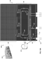
- a physical space 400 in which automated pallet movers may operate is depicted. Similar to FIGS. 1A-B , for example, the example physical space 400 includes staging area 112, transportation area 120, and pallet storage area 103.
- a physical space can include a plurality of pallet handling locations, each pallet handling location being a location from which pallets may be retrieved and/or to which pallets may be transported.
- the physical space 400 includes pallet handling locations 402a-n.
- pallet handling locations may be arranged such that a first row of pallet handling locations are located along a first edge of a physical space, and a second row of pallet handling locations are located along a second edge of the physical space that is different from the first edge.
- pallet handling locations 402a-c are located at an edge of the transportation area 120 that is adjacent to the staging area 112
- pallet handling locations 402d-n are located at an opposite edge of the transportation area 120 that is adjacent to the pallet storage area 103.
- the physical space 400 includes a plurality of lanes 410a-c between the first and second rows of pallet handling locations 402a-n, the lanes 410a-c being configured for use by automated pallet movers 130a-n to transport pallets between the pallet handling locations 402a-n according to routes resulting from performance of a control algorithm for operating according to the lanes 410a-c.
- Lane 410a for example, can be a looping slow lane located along the first row of pallet handling locations 402a-c and the second row of pallet handling locations 402d-n.
- Lane 410b can be a looping fast lane that loops in a same direction (e.g., clockwise or counter-clockwise) as the looping slow lane 410a, and can be located inside of the looping slow lane 410a.
- Lane 410c for example, can be a turning lane that is located inside of the looping fast lane 410b.
- FIG. 4B is flowchart 450 of an example technique for operating automated pallet movers in the example physical space 400 depicted in FIG. 4A , according to the plurality of lanes 410a-c.
- a pallet can be retrieved (452).
- the automated pallet mover 130a can move to pallet handling location 402b and retrieve a pallet that is waiting at that location. After retrieving the pallet, for example, the automated pallet mover 130a can enter and move along the looping slow lane 410a (454). If the automated pallet mover 130a arrives at its destination while travelling in the looping slow lane 410a (456), it may deliver its pallet (458).
- the automated pallet mover 130a may continue travelling in the looping slow lane 410a until it reaches the destination location, and then it may deliver its pallet after it has stopped at the destination location.
- the automated pallet mover 130a can determine whether it is safe to enter the looping fast lane 410b (460). For example, based on information provided to the automated pallet mover 130a by a control system (e.g., computing device 140) regarding locations and speeds of other pallet movers 130n operating in the transportation area 120 and/or based on information collected by its own sensors, the automated pallet mover 130a can determine whether a transition into the looping fast lane 410b is safe, or whether the transition would result in a collision or would impede another automated pallet mover. If such a transition is determined to be unsafe, the automated pallet mover 130a can continue moving along the looping slow lane 410a (454). If such a transition is determined to be safe, the automated pallet mover 130a can transition into the looping fast lane 410b and begin moving along the looping fast lane 410b (462).
- a control system e.g., computing device 140
- the automated pallet mover 130a can continually determine whether it is approaching its destination location (464). If the automated pallet mover 130a determines that it is not close to its destination location (e.g., based on a line that runs perpendicular to the looping fast lane 410b at the current location of the automated pallet mover 130a not being within a threshold distance of the location), for example, the automated pallet mover 130a may continue moving along the looping fast lane 410b (462).
- the automated pallet mover 130a may determine whether it is separated from its destination location by the turning lane 410c at its current location (466). For example, while travelling in the looping fast lane 410b, the automated pallet mover 130a may determine that it is approaching its destination location (e.g., pallet handling location 402e), but that it is separated by turning lane 410c.
- the automated pallet mover 130a may determine whether it is approaching its destination location (e.g., pallet handling location 402e), but that it is separated by turning lane 410c.
- the automated pallet mover 130a can pass its destination location by a suitable distance (e.g., along an x-axis of the transportation area 120), then use the turning lane 410c (468) to enter and cross or move along the fast lane 410b in the opposing direction (462), then quickly approach its destination (464), determine that it is no longer separated by the turning lane 410c (466), and enter the slow lane 410a (470).
- a suitable distance e.g., along an x-axis of the transportation area 120
- the automated pallet mover 130a may determine that it is approaching its destination (464), but that it is not separated by the turning lane 410c (466). In the present example, the automated pallet mover 130a can enter the slow lane 410a (470) without using the turning lane 410c.
- the automated pallet mover 130a may determine that it has arrived at its destination location (456), and then it may deliver its pallet (458) at the destination location. After delivering its pallet, for example, the automated pallet mover 130a may receive another job from the control system, may proceed to a wait area (not shown), may proceed to a charging station (not shown), or may perform another suitable operation.
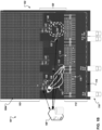
- FIG. 5A an example physical space 500 in which automated pallet movers may operate is depicted. Similar to FIGS. 1A-B and 4A , for example, the example physical space 500 includes staging area 112, transportation area 120, and pallet storage area 103. Similar to FIG 4A , for example, the physical space 500 also includes pallet handling locations 402a-n.
- Lane 510b can be a looping fast lane that loops in a same direction (e.g., clockwise or counter-clockwise) as the looping slow lane 510a, and can be located inside of the looping slow lane 510a.
- Lanes 510c-n can be buffer lanes that are located inside of the looping fast lane 510b and run perpendicular to the looping fast lane 510b.
- FIG. 5B is flowchart of an example technique for operating automated pallet movers in the example physical space 500 depicted in FIG. 5A , according to the plurality of lanes 510a-n.
- a pallet can be retrieved (552).
- the automated pallet mover 130a can move to pallet handling location 402b and retrieve a pallet that is waiting at that location. After retrieving the pallet, for example, the automated pallet mover 130a can enter and move along the looping slow lane 510a (554). If the automated pallet mover 130a arrives at its destination while travelling in the looping slow lane 510a (556), it may deliver its pallet (558).
- the automated pallet mover 130a may continue travelling in the looping slow lane 510a until it reaches the destination location, and then it may deliver its pallet after it has stopped at the destination location.
- the automated pallet mover 130a can determine whether it is safe to enter the looping fast lane 510b (560). For example, based on information provided to the automated pallet mover 130a by a control system (e.g., computing device 140) regarding locations and speeds of other pallet movers 130n operating in the transportation area 120 and/or based on information collected by its own sensors, the automated pallet mover 130a can determine whether a transition into the looping fast lane 510b is safe, or whether the transition would result in a collision or would impede another automated pallet mover. If such a transition is determined to be unsafe, the automated pallet mover 130a can continue moving along the looping slow lane 510a (554). If such a transition is determined to be safe, the automated pallet mover 130a can transition into the looping fast lane 510b and begin moving along the looping fast lane 510b (562).
- a control system e.g., computing device 140
- the automated pallet mover 130a can continually determine whether it is approaching its destination location (564). If the automated pallet mover 130a determines that it is not close to its destination location (e.g., based on a line that runs perpendicular to the looping fast lane 510b at the current location of the automated pallet mover 130a not being within a threshold distance of the location), for example, the automated pallet mover 130a may continue moving along the looping fast lane 510b (562).
- the automated pallet mover 130a may determine whether it is separated from its destination location by one of the buffer lanes 510c-n at its current location (566). For example, while travelling in the looping fast lane 510b, the automated pallet mover 130a may determine that it is approaching its destination location (e.g., pallet handling location 402e), but that it is separated by buffer lane 510n.
- the automated pallet mover 130a may determine whether it is approaching its destination location (e.g., pallet handling location 402e), but that it is separated by buffer lane 510n.
- the automated pallet mover 130a can turn and enter buffer lane 510n, and may potentially wait in the buffer lane 510n (568) while one or more other automated pallet movers (e.g., automated pallet mover 130n) use the buffer lane 510n and/or deliver pallets to the destination location (e.g., pallet handling location 402e). In the present example, after waiting for its turn to clear the buffer lane 510n, the automated pallet mover 130a can proceed to deliver its pallet (558).
- one or more other automated pallet movers e.g., automated pallet mover 130n
- the automated pallet mover 130a can proceed to deliver its pallet (558).
- the automated pallet mover 130a may determine that it is approaching its destination (564), but that it is not separated by any of the buffer lanes 510c-n (566). In the present example, the automated pallet mover 130a can enter the slow lane 510a (570) without using the buffer lane 510c.
- the automated pallet mover 130a may determine that it has arrived at its destination location (556), and then it may deliver its pallet (558) at the destination location. After delivering its pallet, for example, the automated pallet mover 130a may receive another job from the control system, may proceed to a wait area (not shown), may proceed to a charging station (not shown), or may perform another suitable operation.
- FIG. 6A an example physical space 600 in which automated pallet movers may operate is depicted. Similar to FIGS. 1A-B , 4A , and 5A , for example, the example physical space 600 includes staging area 112, transportation area 120, and pallet storage area 103. Similar to FIGS. 4A and 5A , for example, the physical space 600 also includes pallet handling locations 402a-n.
- the physical space 600 includes a plurality of lanes 610a-n being configured for use by automated pallet movers 130a-n to transport pallets between the pallet handling locations 402a-n according to routes resulting from performance of a control algorithm for operating according to the lanes 610a-n.
- the lanes 610a-n can be a series of looping lanes, each lane looping along a different portion of the first and second rows of pallet handling locations, and each adjacent lane looping in a different direction.
- Lane 610a for example, can loop in a clockwise direction along a portion of the first row of pallet handling locations (e.g., a portion including pallet handling location 402a) and a portion of the second row of pallet handling locations (e.g., a portion including pallet handling location 402d).
- Lane 610b for example, can loop in a counterclockwise direction along a different, adjacent portion of the first row of pallet handling locations (e.g., a portion including pallet handling location 402b), and a different, adjacent portion of the second row of pallet handling locations.
- Lane 610c for example, can loop in a clockwise direction along a different, adjacent portion of the first row of pallet handling locations, and a different, adjacent portion of the second row of pallet handling locations (e.g., a portion including pallet handling location 402e).
- Lane 610n for example, can loop in a counterclockwise direction along a different, adjacent portion of the first row of pallet handling locations (e.g., a portion including pallet handling location 402c), and a different, adjacent portion of the second row of pallet handling locations (e.g., a portion including pallet handling location 402n).
- FIG. 6B is flowchart of an example technique for operating automated pallet movers in the example physical space depicted in FIG. 6A , according to the plurality of lanes 610a-n.
- a pallet can be retrieved (652).
- the automated pallet mover 130a can move to pallet handling location 402b and retrieve a pallet that is waiting at that location. After retrieving the pallet, for example, the automated pallet mover 130a can enter and move along the looping lane 610b (654). While moving along the looping lane 610b, for example, the automated pallet mover 130a can continually determine whether it has arrived its destination location (656). If the automated pallet mover 130a arrives at its destination while travelling in the looping lane 610b, for example, it may deliver its pallet (658). If the automated pallet mover 130a has not yet arrived at its destination location, but has determined (660) that its destination is not along another loop, the automated pallet mover 130a can continue moving along its current looping lane 610b (654) until it arrives at its destination.
- the automated pallet mover 130a can move to the other loop (662).
- the automated pallet mover 130a can merge from the counterclockwise looping lane 610b into the clockwise looping lane 610c at a section where the two lanes are adjacent to each other. Moving from one loop to another can be performed by the automated pallet mover 130a, for example, until the automated pallet mover determines (660) that its destination is not along a different loop.
- the automated pallet mover 130a may determine that it has arrived at its destination location (656), and then it may deliver its pallet (658) at the destination location. After delivering its pallet, for example, the automated pallet mover 130a may receive another job from the control system, may proceed to a wait area (not shown), may proceed to a charging station (not shown), or may perform another suitable operation.
- the physical space 700 includes a plurality of lanes 710an, 720, being configured for use by automated pallet movers 130a-n to transport pallets between the pallet handling locations 402a-n according to routes resulting from performance of a control algorithm for operating according to the lanes 710a-n, 720.
- Lane 720 can be an exterior looping lane that loops along the first row of pallet handling locations (e.g., including pallet handling locations 402a-c) and the second row of pallet handling locations (e.g., including pallet handling locations 402d-n).
- the lanes 710a-n can be a series of interior looping lanes, each lane looping along a different portion of the first and second rows of pallet handling locations, each lane looping in a same direction (e.g., clockwise or counterclockwise) as the exterior looping lane 720, and each lane overlapping with portions of exterior looping lane 720.
- Lane 710a for example, can loop along a portion of the first row of pallet handling locations (e.g., a portion including pallet handling location 402a) and a portion of the second row of pallet handling locations (e.g., a portion including pallet handling location 402d).
- Lane 710b can loop along a different, adjacent portion of the first row of pallet handling locations (e.g., a portion including pallet handling location 402b), and a different, adjacent portion of the second row of pallet handling locations.
- Lane 710c for example, can loop along a different, adjacent portion of the first row of pallet handling locations, and a different, adjacent portion of the second row of pallet handling locations (e.g., a portion including pallet handling location 402e).
- Lane 710n for example, can loop along a different, adjacent portion of the first row of pallet handling locations (e.g., a portion including pallet handling location 402c), and a different, adjacent portion of the second row of pallet handling locations (e.g., a portion including pallet handling location 402n).
- FIG. 7B is flowchart of an example technique for operating automated pallet movers in the example physical space depicted in FIG. 7A , according to the plurality of lanes 710a-n, 720.
- a pallet can be retrieved (752).
- the automated pallet mover 130a can move to pallet handling location 402b and retrieve a pallet that is waiting at that location.
- the automated pallet mover 130a can enter and move along the exterior looping lane 720 (754). While moving along the exterior looping lane 720, for example, the automated pallet mover 130a can continually determine whether it has arrived its destination location (656). If the automated pallet mover 130a arrives at its destination while travelling in the exterior looping lane 720, for example, it may deliver its pallet (758).
- the automated pallet mover 130a can continue moving along the exterior looping lane 720 (754) until it arrives at its destination.
- the automated pallet mover 130a may determine that it has arrived at its destination location (756), and then it may deliver its pallet (758) at the destination location. After delivering its pallet, for example, the automated pallet mover 130a may receive another job from the control system, may proceed to a wait area (not shown), may proceed to a charging station (not shown), or may perform another suitable operation.
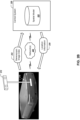
- FIG. 8 is a flowchart of an example technique 800 for selecting an optimal control algorithm for operating automated pallet movers in a physical space.
- one or more of the lane configurations and corresponding control algorithms described with respect to FIGS. 4-7 and/or the technique 300 for determining optimal routes for transporting optimal routes described with respect to FIG. 3 may be optimal for transporting pallets in the warehouse 102, based on current warehouse conditions (e.g., currently available automated pallet movers and current jobs to be performed by the automated pallet movers).
- the example technique 800 can be performed by any of a variety of appropriate systems, such as the example systems depicted in FIGS. 1A-B .
- warehouse data is received that pertains to current and/or projected conditions in a warehouse.
- the computing device 140 shown in FIGS. 1A-B
- can receive warehouse condition data including data that identifies available automated pallet movers 130, data that identifies capabilities of the automated pallet movers 130 (e.g., speed capabilities, sensor capabilities, pallet manipulation capabilities, weight capacities, power levels, etc.), and data that identifies jobs to be performed by the automated pallet movers 130 in the warehouse 102.
- Data that identifies the jobs to be performed can include data specifying pallets to be transported in the warehouse 102 (e.g., pallet identifiers, pallet size and weight specifications, goods carried by the pallets, etc.), current and/or anticipated locations of the pallets, and destination locations of the pallets.
- pallets to be transported in the warehouse 102 e.g., pallet identifiers, pallet size and weight specifications, goods carried by the pallets, etc.
- current and/or anticipated locations of the pallets e.g., current and/or anticipated locations of the pallets, and destination locations of the pallets.
- one or more simulations of transporting pallets in the warehouse can be performed, according to each of a plurality of control algorithms.
- the computing device 140 can perform one or more simulations that process a list of warehouse pallet transportation jobs to be performed (e.g., including pallet identifiers, start locations of the pallets, and destination locations of the pallets), using available automated pallet movers 130, according to the lane configurations and corresponding control algorithms described with respect to each of FIGS. 4A-B , 5A-B , 6A-B , 7A-B , and other potentially suitable configurations/algorithms.
- the computing device 140 can determine, from the performed simulations, and for each control algorithm, an amount of time that it takes to finish the list of warehouse pallet transportation jobs, an amount of power consumed by the automated pallet movers 130 to perform the jobs, a suitable number of automated pallet movers 130 to be assigned the jobs (e.g., to avoid traffic congestion), and other such simulation results.
- an optimal control algorithm is selected and applied.
- the computing device 140 can select the optimal control algorithm based on pallet throughput (e.g., an amount of time to complete a list of jobs or a portion of the list of jobs), a number of automated pallet movers 130 used for completing a list of pallet transportation jobs, an amount of power expected to be consumed while completing the jobs, another suitable factor, or a weighted combination of factors.
- the computing device 140 can send to each of the automated pallet movers 130 that are designated for working on the pallet transportation jobs, a control algorithm command that causes the automated pallet movers to perform subsequent operations (e.g., pallet transportation) according to a corresponding control algorithm.
- sending the control algorithm command may include sending instructions for performing the control algorithm and/or location data that defines lanes to be used while performing the control algorithm.
- the example technique 800 for selecting an optimal control algorithm for operating automated pallet movers in a physical space can be periodically performed. For example, at a suitable time interval (e.g., once per hour, once every four hours, once per day, or another suitable time interval), further simulations can be performed, efficiencies resulting from simulated performance of the control algorithms can be compared, and possibly a different control algorithm can be selected and applied.
- the example technique 800 can be performed in response to a warehouse event, such as one or more pallet transportation jobs being added to a list, one or more trucks arriving at a docking bay, or another sort of event. By periodically simulating use of the various control algorithms, for example, an optimal control algorithm may be applied in response to changing warehouse conditions.
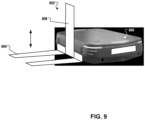
- FIG. 9 illustrates another example AGV 900.
- the AGV 900 can be used for the AGVs described throughout this document, such as those described above with regard to FIGS. 1-8 .
- the automated vehicle 900 can lift a pallet from the ground for transportation without losing flexibility of the automated vehicle 900 in moving freely in/out and within various areas in a warehouse environment, such as assembly areas, dock areas, case pick areas, etc.
- the automated vehicle 900 includes a pallet lift structure 902 having forks 904 for supporting an underneath of a pallet, and a fork lift mechanism 906 for vertically moving the forks 904 with respect to the ground.
- AGVs that are configured to carry pallets on their top surface may be configured to move faster through a warehouse while carrying a pallet than AGVs with forks, such as the AGV 900.
- the AGVs carrying pallets on their top surface may not be able to lift and lower pallets from a ground surface.
- loading and unloading the pallets on their top surface can involve the pallets already being positioned above the ground at an appropriate level for the AGVs to transition the pallets onto their top surface, such as pallets being positioned on a conveyor belt at an appropriate height, being positioned on a stand at an appropriate height, being held by a forklift/AGV at an appropriate height, and/or other mechanisms for retaining pallets at an appropriate height.
- a forklift-type device such as the AGV 900 and/or manually operated forklifts.
- the following description details a variety of configurations for using different types of AGVs in different areas of the warehouse to provide such height transitions for pallets in an efficient manner, such as using the AGVs 900 in different configurations in the staging area 112 and/or the pallet transportation area 120.
- FIGS. 10A-C depict example warehouse environments 1000, 1010, and 1020 in which multiple different types of AGVs are used and controlled in traffic patterns so as to improve the overall efficiency of the warehouse.
- FIGS. 10A-C reference many of the same components of system 100 described above with regard to FIG. 1A .
- a first type of AGV 1004 are controlled by the computer system 140 to operate in a first pattern 1002 to move pallets in the pallet transportation area 120 between the conveyors 116 and the automated storage system 103.
- the first type of AGVs 1004 can be AGVs that transport pallets on their top surface, such as the AGVs 200 and 210.
- the first pattern 1002 can be any of the patterns described above with regard to FIGS. 4A , 5A , 6A , and 7A , and/or other patterns.
- Pallets can be transported in the staging area by a second type of AGV 1008 which can be controlled by the computer system 140 to move according to a second pattern 1006.
- the AGVs 1008 can be AGVs capable of lifting and placing pallets on a ground surface, such as the AGV 900.
- the AGVs 1008 can transport pallets between the trucks 115 and the decks/conveyors 116, and can be controlled to according to the traffic pattern 1006, which is depicted as simple collection of straight lines between the decks/conveyors 116 and the trucks 114.
- Other traffic patterns can be used for the second type of AGVs 1008, such as the patterns described above with regard to FIGS. 4A , 5A , 6A , and 7A , and/or other patterns.
- the first type of AGV 1004 may operate at a higher rate of speed than the second type of AGV 1008, the first type of AGV 1004 may be tasked with moving pallets laterally across the warehouse to the appropriate deck/conveyor, and the AGVs 1008 may instead restrict their movement to more vertical movement, minimizing their drive time and the complexity of their traffic pattern.
- Such a configuration of the relative patterns and movements of the AGVs 1004 and 1008 can minimize the lateral travel time for pallets throughout the warehouse, and can maximize the pallet throughput.
- AGVs 1008 may be reassigned to different vertical traffic paths, which may be changed, created, and deprecated depending on the trucks 114 that are currently parked in the bays 115 for loading and unloading.
- FIG. 10B in this example environment 1010 the decks/conveyors from environment 1000 ( FIG. 10A ) have been removed and instead replaced by the second type of AGV 1008, which move pallets between the trucks 114 and the first type of AGVs 1004 according to the traffic patterns 1012.
- the second type of AGV 1008 can load and unload pallets from the first type of AGV 1004, and/or can place them on stands from which the first type of AGVs 1004 can load and unload pallets.
- This configuration in environment 1010 can provide additional flexibility and configurability by removing physical conveyors, which are replaced by the second type of AGVs 1008 and their readily configurable traffic patterns 1012.
- Loading trucks with well-aligned and stored pallets may not have the same types of problems, and may be more consistently able to be performed by the second type of AGVs 1008 without human-operated forklifts 1024.
- the second type of AGVs 1008 may by default perform the truck loading and unloading, and may signal for human intervention by the human-operated forklifts 1024 when instances are encountered in which the AGVs 1008 are not able to safely perform the task.
- FIG. 11 is a block diagram of computing devices 1100, 1150 that may be used to implement the systems and methods described in this document, as either a client or as a server or plurality of servers.
- Computing device 1100 is intended to represent various forms of digital computers, such as laptops, desktops, workstations, personal digital assistants, servers, blade servers, mainframes, and other appropriate computers.
- Computing device 1150 is intended to represent various forms of mobile devices, such as personal digital assistants, cellular telephones, smartphones, and other similar computing devices.
- the components shown here, their connections and relationships, and their functions, are meant to be examples only, and are not meant to limit implementations described and/or claimed in this document.
- Computing device 1100 includes a processor 1102, memory 1104, a storage device 1106, a high-speed interface 1108 connecting to memory 1104 and high-speed expansion ports 1110, and a low speed interface 1112 connecting to low speed bus 1114 and storage device 1106.
- Each of the components 1102, 1104, 1106, 1108, 1110, and 1112, are interconnected using various busses, and may be mounted on a common motherboard or in other manners as appropriate.
- the processor 1102 can process instructions for execution within the computing device 1100, including instructions stored in the memory 1104 or on the storage device 1106 to display graphical information for a GUI on an external input/output device, such as display 1116 coupled to high-speed interface 1108.
- multiple processors and/or multiple buses may be used, as appropriate, along with multiple memories and types of memory.
- multiple computing devices 1100 may be connected, with each device providing portions of the necessary operations (e.g., as a server bank, a group of blade servers, or a multi-processor system).
- the memory 1104 stores information within the computing device 1100.
- the memory 1104 is a volatile memory unit or units.
- the memory 1104 is a non-volatile memory unit or units.
- the memory 1104 may also be another form of computer-readable medium, such as a magnetic or optical disk.
- the storage device 1106 is capable of providing mass storage for the computing device 1100.
- the storage device 1106 may be or contain a computer-readable medium, such as a floppy disk device, a hard disk device, an optical disk device, or a tape device, a flash memory or other similar solid state memory device, or an array of devices, including devices in a storage area network or other configurations.
- a computer program product can be tangibly embodied in an information carrier.
- the computer program product may also contain instructions that, when executed, perform one or more methods, such as those described above.
- the information carrier is a computer- or machine-readable medium, such as the memory 1104, the storage device 1106, or memory on processor 1102.
- the high-speed controller 1108 manages bandwidth-intensive operations for the computing device 1100, while the low speed controller 1112 manages lower bandwidth-intensive operations. Such allocation of functions is an example only.
- the high-speed controller 1108 is coupled to memory 1104, display 1116 (e.g., through a graphics processor or accelerator), and to high-speed expansion ports 1110, which may accept various expansion cards (not shown).
- low-speed controller 1112 is coupled to storage device 1106 and low-speed expansion port 1114.
- the low-speed expansion port which may include various communication ports (e.g., USB, Bluetooth, Ethernet, wireless Ethernet) may be coupled to one or more input/output devices, such as a keyboard, a pointing device, a scanner, or a networking device such as a switch or router, e.g., through a network adapter.
- input/output devices such as a keyboard, a pointing device, a scanner, or a networking device such as a switch or router, e.g., through a network adapter.
- the computing device 1100 may be implemented in a number of different forms, as shown in the figure. For example, it may be implemented as a standard server 1120, or multiple times in a group of such servers. It may also be implemented as part of a rack server system 1124. In addition, it may be implemented in a personal computer such as a laptop computer 1122. Alternatively, components from computing device 1100 may be combined with other components in a mobile device (not shown), such as device 1150. Each of such devices may contain one or more of computing device 1100, 1150, and an entire system may be made up of multiple computing devices 1100, 1150 communicating with each other.
- Computing device 1150 includes a processor 1152, memory 1164, an input/output device such as a display 1154, a communication interface 1166, and a transceiver 1168, among other components.
- the device 1150 may also be provided with a storage device, such as a microdrive or other device, to provide additional storage.
- a storage device such as a microdrive or other device, to provide additional storage.
- Each of the components 1150, 1152, 1164, 1154, 1166, and 1168, are interconnected using various buses, and several of the components may be mounted on a common motherboard or in other manners as appropriate.
- the processor 1152 can execute instructions within the computing device 1150, including instructions stored in the memory 1164.
- the processor may be implemented as a chipset of chips that include separate and multiple analog and digital processors. Additionally, the processor may be implemented using any of a number of architectures.
- the processor may be a CISC (Complex Instruction Set Computers) processor, a RISC (Reduced Instruction Set Computer) processor, or a MISC (Minimal Instruction Set Computer) processor.
- the processor may provide, for example, for coordination of the other components of the device 1150, such as control of user interfaces, applications run by device 1150, and wireless communication by device 1150.
- Processor 1152 may communicate with a user through control interface 1158 and display interface 1156 coupled to a display 1154.
- the display 1154 may be, for example, a TFT (Thin-Film-Transistor Liquid Crystal Display) display or an OLED (Organic Light Emitting Diode) display, or other appropriate display technology.
- the display interface 1156 may comprise appropriate circuitry for driving the display 1154 to present graphical and other information to a user.
- the control interface 1158 may receive commands from a user and convert them for submission to the processor 1152.
- an external interface 1162 may be provide in communication with processor 1152, so as to enable near area communication of device 1150 with other devices.
- External interface 1162 may be provided, for example, for wired communication in some implementations, or for wireless communication in other implementations, and multiple interfaces may also be used.
- the memory 1164 stores information within the computing device 1150.
- the memory 1164 can be implemented as one or more of a computer-readable medium or media, a volatile memory unit or units, or a non-volatile memory unit or units.
- Expansion memory 1174 may also be provided and connected to device 1150 through expansion interface 1172, which may include, for example, a SIMM (Single In Line Memory Module) card interface.
- SIMM Single In Line Memory Module
- expansion memory 1174 may provide extra storage space for device 1150, or may also store applications or other information for device 1150.
- expansion memory 1174 may include instructions to carry out or supplement the processes described above, and may include secure information also.
- expansion memory 1174 may be provide as a security module for device 1150, and may be programmed with instructions that permit secure use of device 1150.
- secure applications may be provided via the SIMM cards, along with additional information, such as placing identifying information on the SIMM card in a non-hackable manner.
- implementations of the systems and techniques described here can be realized in digital electronic circuitry, integrated circuitry, specially designed ASICs (application specific integrated circuits), computer hardware, firmware, software, and/or combinations thereof.
- ASICs application specific integrated circuits
- These various implementations can include implementation in one or more computer programs that are executable and/or interpretable on a programmable system including at least one programmable processor, which may be special or general purpose, coupled to receive data and instructions from, and to transmit data and instructions to, a storage system, at least one input device, and at least one output device.
- the computing system can include clients and servers.
- a client and server are generally remote from each other and typically interact through a communication network.
- the relationship of client and server arises by virtue of computer programs running on the respective computers and having a client-server relationship to each other.
Landscapes
- Engineering & Computer Science (AREA)
- Remote Sensing (AREA)
- Radar, Positioning & Navigation (AREA)
- Physics & Mathematics (AREA)
- General Physics & Mathematics (AREA)
- Automation & Control Theory (AREA)
- Business, Economics & Management (AREA)
- Aviation & Aerospace Engineering (AREA)
- Mechanical Engineering (AREA)
- Economics (AREA)
- Computer Vision & Pattern Recognition (AREA)
- Operations Research (AREA)
- Human Resources & Organizations (AREA)
- Strategic Management (AREA)
- General Business, Economics & Management (AREA)
- Quality & Reliability (AREA)
- Theoretical Computer Science (AREA)
- Marketing (AREA)
- Entrepreneurship & Innovation (AREA)
- Development Economics (AREA)
- Tourism & Hospitality (AREA)
- Artificial Intelligence (AREA)
- Medical Informatics (AREA)
- Health & Medical Sciences (AREA)
- Evolutionary Computation (AREA)
- Software Systems (AREA)
- Multimedia (AREA)
- Electromagnetism (AREA)
- Accounting & Taxation (AREA)
- Finance (AREA)
- Warehouses Or Storage Devices (AREA)
- Stacking Of Articles And Auxiliary Devices (AREA)
- Pallets (AREA)
Claims (14)
- Système d'entrepôt automatisé (100, 101), le système comprenant :une pluralité de dispositifs automatisés de déplacement de palettes (130),un espace physique (120) dans lequel la pluralité de dispositifs automatisés de déplacement de palettes sont configurés pour travailler, etun système de commande (140) configuré pour fournir des instructions à chacun de la pluralité de dispositifs automatisés de déplacement de palettes pour travailler dans l'espace physique, les instructions comprenant, pour un dispositif automatisé de déplacement de palettes :une instruction de transport de palette comprenant :(i) un identifiant de palette d'une palette (110) à transporter par le dispositif automatisé de déplacement de palettes dans l'espace physique, et(ii) un emplacement de destination jusqu'auquel la palette doit être transportée par le dispositif automatisé de déplacement de palettes, etune instruction d'algorithme de commande qui spécifie un algorithme de commande pour un déplacement à travers l'espace physique, dans lequel le dispositif automatisé de déplacement de palettes est configuré pour transporter la palette jusqu'à l'emplacement de destination selon un itinéraire résultant d'une exécution de l'algorithme de commande, tandis qu'un ou plusieurs des autres dispositifs automatisés de déplacement de palettes transportent simultanément d'autres palettes jusqu'à d'autres emplacements de destination selon d'autres itinéraires résultant d'une exécution du même algorithme de commande ; caractérisé en ce quele système de commande est configuré en outre pour :(i) pour chacun d'une pluralité d'algorithmes de commande différents, exécuter (804) une ou plusieurs simulations de transport de palettes dans l'espace physique par la pluralité de dispositifs automatisés de déplacement de palettes en utilisant l'algorithme de commande,(ii) comparer (806) une capacité de traitement de palettes résultant d'une utilisation simulée de chaque algorithme de commande, et(iii) sélectionner (808) un algorithme de commande optimal, l'algorithme de commande optimal correspondant à une capacité de traitement de palettes supérieure, dans lequel l'instruction d'algorithme de commande spécifie l'algorithme de commande optimal.
- Système d'entrepôt automatisé selon la revendication 1, dans lequel au moins un des dispositifs automatisés de déplacement de palettes est un véhicule guidé automatisé (200).
- Système d'entrepôt automatisé selon la revendication 1 ou 2, dans lequel au moins un des dispositifs automatisés de déplacement de palettes inclut un dispositif lève-palette.
- Système d'entrepôt automatisé selon l'une quelconque des revendications 1 à 3, dans lequel l'identifiant de palette est associé à un emplacement de la palette dans l'espace physique.
- Système d'entrepôt automatisé selon l'une quelconque des revendications 1 à 4, dans lequel :
après la fourniture, à chacun des dispositifs automatisés de déplacement de palettes, de l'instruction d'algorithme de commande qui spécifie l'algorithme de commande pour le déplacement à travers l'espace physique, le système de commande est configuré pour fournir, à chacun des dispositifs automatisés de déplacement de palettes, une deuxième instruction d'algorithme de commande différente qui spécifie un deuxième algorithme de commande différent pour le déplacement à travers l'espace physique. - Système d'entrepôt automatisé selon l'une quelconque des revendications 1 à 5, dans lequel l'itinéraire emprunté par le dispositif de déplacement de palettes résultant d'une exécution de l'algorithme de commande est déterminé en temps réel, en réponse à des emplacements et des déplacements des autres dispositifs de déplacement de palettes dans l'espace physique.
- Système d'entrepôt automatisé selon l'une quelconque des revendications 1 à 6, dans lequel l'espace physique inclut une pluralité d'emplacements de manutention de palettes, chaque emplacement de manutention de palettes étant un emplacement à partir duquel des palettes sont prélevées et/ou vers lequel des palettes sont transportées, dans lequel :
au moins un emplacement de manutention de palettes est situé à l'extrémité d'une bande transporteuse dans l'espace physique ou est une zone dédiée sur un sol de l'espace physique. - Système d'entrepôt automatisé selon la revendication 7, dans lequel la pluralité d'emplacements de manutention de palettes sont disposés de sorte qu'une première rangée d'emplacements de manutention de palettes sont situés le long d'un premier bord de l'espace physique, et une deuxième rangée d'emplacements de manutention de palettes sont situés le long d'un deuxième bord de l'espace physique différent du premier bord.
- Système d'entrepôt automatisé selon la revendication 8, dans lequel l'espace physique inclut une pluralité de voies entre la première et la deuxième rangée d'emplacements de manutention de palettes, les voies étant configurées pour une utilisation par les dispositifs automatisés de déplacement de palettes pour transporter des palettes entre des emplacements de manutention de palettes selon des itinéraires résultant d'une exécution de l'algorithme de commande, dans lequel au moins une voie est une voie virtuelle ou est une voie signalée.
- Système d'entrepôt automatisé selon la revendication 9, dans lequel l'algorithme de commande et un algorithme de commande différent sont associés chacun à une pluralité différente de voies.
- Système d'entrepôt automatisé selon l'une quelconque des revendications 9 et 10, dans lequel la pluralité de voies comprend :(i) une voie en boucle lente située le long de la première rangée d'emplacements de manutention de palettes et de la deuxième rangée d'emplacements de manutention de palettes,(ii) une voie en boucle rapide qui forme une boucle dans une même direction que la voie en boucle lente et est située à l'intérieur de la voie en boucle lente, et(iii) une voie de retournement qui est située à l'intérieur de la voie en boucle rapide.
- Système d'entrepôt automatisé selon l'une quelconque des revendications 9 et 10, dans lequel la pluralité de voies comprend :(i) une voie en boucle lente située le long de la première rangée d'emplacements de manutention de palettes et de la deuxième rangée d'emplacements de manutention de palettes,(ii) une voie en boucle rapide qui forme une boucle dans une même direction que la voie en boucle lente et est située à l'intérieur de la voie en boucle lente, et(iii) une pluralité de voies tampon qui sont situées à l'intérieur de la voie en boucle rapide.
- Système d'entrepôt automatisé selon l'une quelconque des revendications 9 et 10, dans lequel la pluralité de voies comprend :(i) une première voie en boucle qui forme une boucle dans le sens des aiguilles d'une montre le long d'une partie de la première rangée d'emplacements de manutention de palettes et d'une partie de la deuxième rangée d'emplacements de manutention de palettes, et(ii) une deuxième voie en boucle qui forme une boucle dans le sens inverse des aiguilles d'une montre le long d'une partie différente de la première rangée d'emplacements de manutention de palettes et d'une partie différente de la deuxième rangée d'emplacements de manutention de palettes.
- Système d'entrepôt automatisé selon l'une quelconque des revendications 9 et 10, dans lequel la pluralité de voies comprend :(i) une voie en boucle extérieure qui forme une boucle le long de la première rangée d'emplacements de manutention de palettes et de la deuxième rangée d'emplacements de manutention de palettes, et(ii) une pluralité de voies en boucle intérieures qui forment une boucle dans une même direction que la voie en boucle extérieure, chaque voie en boucle intérieure formant une boucle à l'intérieur de la voie en boucle extérieure.
Priority Applications (1)
| Application Number | Priority Date | Filing Date | Title |
|---|---|---|---|
| EP25178331.2A EP4583026A3 (fr) | 2019-04-08 | 2020-04-08 | Commande de dispositifs de déplacement de palettes automatisés |
Applications Claiming Priority (5)
| Application Number | Priority Date | Filing Date | Title |
|---|---|---|---|
| US201962830904P | 2019-04-08 | 2019-04-08 | |
| US201962831695P | 2019-04-09 | 2019-04-09 | |
| US201962880640P | 2019-07-30 | 2019-07-30 | |
| US201962880638P | 2019-07-30 | 2019-07-30 | |
| PCT/US2020/027338 WO2020210406A1 (fr) | 2019-04-08 | 2020-04-08 | Commande de dispositifs automatisés de déplacement de palettes |
Related Child Applications (2)
| Application Number | Title | Priority Date | Filing Date |
|---|---|---|---|
| EP25178331.2A Division EP4583026A3 (fr) | 2019-04-08 | 2020-04-08 | Commande de dispositifs de déplacement de palettes automatisés |
| EP25178331.2A Division-Into EP4583026A3 (fr) | 2019-04-08 | 2020-04-08 | Commande de dispositifs de déplacement de palettes automatisés |
Publications (5)
| Publication Number | Publication Date |
|---|---|
| EP3953778A1 EP3953778A1 (fr) | 2022-02-16 |
| EP3953778A4 EP3953778A4 (fr) | 2023-07-05 |
| EP3953778B1 true EP3953778B1 (fr) | 2025-07-09 |
| EP3953778C0 EP3953778C0 (fr) | 2025-07-09 |
| EP3953778B8 EP3953778B8 (fr) | 2026-01-14 |
Family
ID=72663005
Family Applications (3)
| Application Number | Title | Priority Date | Filing Date |
|---|---|---|---|
| EP20787294.6A Pending EP3953282A4 (fr) | 2019-04-08 | 2020-04-08 | Transport automatique de palettes de marchandises |
| EP25178331.2A Pending EP4583026A3 (fr) | 2019-04-08 | 2020-04-08 | Commande de dispositifs de déplacement de palettes automatisés |
| EP20788441.2A Active EP3953778B8 (fr) | 2019-04-08 | 2020-04-08 | Commande de dispositifs automatisés de déplacement de palettes |
Family Applications Before (2)
| Application Number | Title | Priority Date | Filing Date |
|---|---|---|---|
| EP20787294.6A Pending EP3953282A4 (fr) | 2019-04-08 | 2020-04-08 | Transport automatique de palettes de marchandises |
| EP25178331.2A Pending EP4583026A3 (fr) | 2019-04-08 | 2020-04-08 | Commande de dispositifs de déplacement de palettes automatisés |
Country Status (8)
| Country | Link |
|---|---|
| US (9) | US10809727B1 (fr) |
| EP (3) | EP3953282A4 (fr) |
| CN (1) | CN114222708B (fr) |
| AU (3) | AU2020271069B2 (fr) |
| CA (1) | CA3136541C (fr) |
| ES (1) | ES3036230T3 (fr) |
| NZ (1) | NZ781258A (fr) |
| WO (2) | WO2020210406A1 (fr) |
Families Citing this family (54)
| Publication number | Priority date | Publication date | Assignee | Title |
|---|---|---|---|---|
| US20190185012A1 (en) | 2017-12-18 | 2019-06-20 | PlusAI Corp | Method and system for personalized motion planning in autonomous driving vehicles |
| US11130497B2 (en) | 2017-12-18 | 2021-09-28 | Plusai Limited | Method and system for ensemble vehicle control prediction in autonomous driving vehicles |
| US11273836B2 (en) | 2017-12-18 | 2022-03-15 | Plusai, Inc. | Method and system for human-like driving lane planning in autonomous driving vehicles |
| US10967892B2 (en) * | 2018-11-08 | 2021-04-06 | Rockwell Automation Technologies, Inc. | Independent cart system and method of operating the same |
| EP3953282A4 (fr) | 2019-04-08 | 2022-11-30 | Lineage Logistics, LLC | Transport automatique de palettes de marchandises |
| US10796278B1 (en) * | 2019-11-19 | 2020-10-06 | Lineage Logistics, LLC | Optimizing pallet location in a warehouse |
| JP7340472B2 (ja) * | 2020-02-06 | 2023-09-07 | 株式会社日立インダストリアルプロダクツ | シミュレーション装置、シミュレーションシステム、搬送システム及びシミュレーション方法 |
| DE102020203207A1 (de) * | 2020-03-12 | 2021-09-16 | Pascal Gysin | Paletten-Verwaltungssystem zum Verwalten von Paletten |
| EP3913526A1 (fr) * | 2020-05-18 | 2021-11-24 | CHEP Technology Pty Limited | Détection de plateformes |
| US20230251098A1 (en) * | 2020-06-30 | 2023-08-10 | Nec Corporation | Information processing apparatus, mobile-body control system, and information processing method |
| IT202000016834A1 (it) * | 2020-07-10 | 2022-01-10 | Sacmi | Metodo ed impianto per la gestione di articoli ceramici |
| WO2022040809A1 (fr) | 2020-08-28 | 2022-03-03 | Langen H J Paul | Système d'entrepôt pour satisfaire des commandes |
| CN113762849B (zh) * | 2020-11-06 | 2024-07-19 | 北京京东乾石科技有限公司 | 立体仓库库存管理的方法、装置和系统 |
| US12159260B2 (en) * | 2020-12-15 | 2024-12-03 | Target Brands, Inc. | Coordination platform for warehouse operations |
| JP7478849B2 (ja) * | 2020-12-28 | 2024-05-07 | 本田技研工業株式会社 | ロボット管理システム |
| ES2958564T3 (es) * | 2021-03-03 | 2024-02-09 | Fameccanica Data Spa | Una planta de embalaje y un procedimiento para el embalaje de productos |
| PL4053026T3 (pl) | 2021-03-03 | 2025-10-06 | Fameccanica.Data S.P.A. | Instalacje opakowaniowe i sposoby pakowania produktów |
| CN117120801A (zh) * | 2021-03-31 | 2023-11-24 | 松下知识产权经营株式会社 | 测定装置以及测定方法 |
| JP7633868B2 (ja) * | 2021-04-13 | 2025-02-20 | シャープ株式会社 | 搬送システム、搬送方法、及び搬送プログラム |
| AU2022284873A1 (en) * | 2021-06-02 | 2023-11-30 | Lineage Logistics, LLC | Determining locations at which to store items in a storage facility |
| AU2022286422B2 (en) * | 2021-06-02 | 2025-03-13 | Lineage Logistics, LLC | Determining items to pick in a storage facility |
| US12125186B2 (en) * | 2021-06-10 | 2024-10-22 | Zebra Technologies Corporation | Collision mitigation systems and methods |
| US11629009B2 (en) | 2021-07-14 | 2023-04-18 | Newteq Holding B.V. | Automated warehouse systems, assemblies, apparatuses, and methods for assembling mixed pallets and facilitating order picking |
| CN113657833B (zh) * | 2021-08-20 | 2024-04-16 | 北京京东振世信息技术有限公司 | 物资盘点方法、装置、设备以及存储介质 |
| JP7680025B2 (ja) * | 2021-09-15 | 2025-05-20 | ユーピーアール株式会社 | 荷物管理システム |
| US12606379B2 (en) * | 2021-09-30 | 2026-04-21 | Symbotic Llc | Automatic storage and retrieval system having staging and sequencing buffer locations and segregated storage |
| WO2023084637A1 (fr) * | 2021-11-10 | 2023-05-19 | 株式会社LexxPluss | Système de transport et procédé de commande de transport |
| DE102021130984A1 (de) * | 2021-11-25 | 2023-05-25 | Jungheinrich Aktiengesellschaft | Verfahren zum Planen einer Route für ein fahrerloses Transportfahrzeug |
| CN114355885A (zh) * | 2021-12-03 | 2022-04-15 | 中国信息通信研究院 | 基于agv小车的协作机器人搬运系统及方法 |
| US11860592B2 (en) * | 2021-12-22 | 2024-01-02 | Ford Global Technologies, Llc | Systems and methods for training a reinforcement learning system for pallet routing in a manufacturing environment |
| US12602035B2 (en) | 2021-12-22 | 2026-04-14 | Ford Global Technologies, Llc | Systems and methods for defining a sensor layout for pallet routing in a manufacturing environment |
| CA3242936A1 (fr) * | 2022-01-11 | 2023-07-20 | Lineage Logistics, LLC | Planification et commande de moyens automatises de prelevement de couches |
| US12545516B2 (en) * | 2022-01-11 | 2026-02-10 | Lineage Logistics, LLC | Coordinating automated pallet movers and conveying systems in an automated warehouse |
| FR3133186B1 (fr) * | 2022-03-04 | 2024-04-26 | Transp Bernis | Dispositif de signalisation pour une chaîne de tri, chaîne de tri et procédé associés |
| JP7611183B2 (ja) * | 2022-03-16 | 2025-01-09 | 三菱重工業株式会社 | 情報処理装置、移動制御システム、情報処理方法及びプログラム |
| US20230368119A1 (en) * | 2022-05-13 | 2023-11-16 | United States Postal Service | Systems and methods for using machine vision in distribution facility operations and tracking distribution items |
| US20230393582A1 (en) * | 2022-06-06 | 2023-12-07 | International Business Machines Corporation | Simulated results-based material movement at industrial area |
| WO2024010853A1 (fr) * | 2022-07-06 | 2024-01-11 | Rehrig Pacific Company | Robots mobiles automatisés pour livraison automatisée et livraison assistée |
| EP4612073A1 (fr) * | 2022-11-11 | 2025-09-10 | Lights-Out Fulfillment Systems Inc. | Exécution de commande hybride |
| DE102023125101A1 (de) * | 2022-11-15 | 2024-05-16 | Gebhardt Fördertechnik GmbH | Shuttle-System und Verfahren zum Betreiben eines Shuttle-Systems |
| US12612268B2 (en) * | 2023-01-12 | 2026-04-28 | Solaredge Technologies Ltd. | System and method for monitoring components moving in automated feed system |
| CN118483963A (zh) * | 2023-02-10 | 2024-08-13 | 纬创资通(重庆)有限公司 | 自动化系统及其控制方法 |
| JP2024140083A (ja) * | 2023-03-28 | 2024-10-10 | 株式会社ダイフク | 物品搬送設備 |
| US20240327123A1 (en) * | 2023-03-30 | 2024-10-03 | Coupang Corp. | Systems and methods for automatic product intake, stocking, and retrieval |
| JP2024172236A (ja) * | 2023-05-31 | 2024-12-12 | 三菱重工業株式会社 | 搬送システム、搬送方法及びプログラム |
| US12521885B2 (en) | 2023-09-21 | 2026-01-13 | Knauf Gips Kg | Robotic wallboard dunnage placement system |
| CN117104750B (zh) * | 2023-09-25 | 2025-09-30 | 湖州美欣达机动车回收拆解有限公司 | 回收机动车仓储系统及使用方法 |
| JP2025079427A (ja) * | 2023-11-10 | 2025-05-22 | 株式会社ダイフク | 搬送設備 |
| CN117485782B (zh) * | 2023-11-22 | 2025-11-21 | 四川启睿克科技有限公司 | 一种装箱物料转运方法及系统、计算设备 |
| US12275606B1 (en) * | 2023-12-27 | 2025-04-15 | Niagara Bottling, Llc | Facility layout |
| US12265400B1 (en) | 2023-12-27 | 2025-04-01 | Niagara Bottling, Llc | Facility layout |
| TWI902122B (zh) * | 2024-01-11 | 2025-10-21 | 鄭用文 | 載具管理系統以及方法 |
| WO2026015559A1 (fr) * | 2024-07-09 | 2026-01-15 | Msip Holdings, Llc | Système de planification de mission |
| TWI907103B (zh) * | 2024-10-14 | 2025-12-01 | 沃德瑞克智能倉儲設備有限公司 | 基於自動庫的出庫任務動態分配的方法與系統 |
Family Cites Families (35)
| Publication number | Priority date | Publication date | Assignee | Title |
|---|---|---|---|---|
| US1024227A (en) | 1911-11-27 | 1912-04-23 | Ivan Rocic | Caster-wheel. |
| FR2848538A1 (fr) * | 2002-12-13 | 2004-06-18 | Neopost Nbg | Systeme de collecte et de verification automatique de commandes d'objets |
| CN1308202C (zh) * | 2003-11-09 | 2007-04-04 | 昆明昆船物流信息产业有限公司 | 小件物料机器人码垛系统托盘输送装置 |
| CA2558626C (fr) * | 2006-09-21 | 2008-05-20 | Tenxc Wireless Inc. | Radiolocalisation ultra precise de radiobalises dans un entrepot |
| US20080131255A1 (en) | 2006-11-30 | 2008-06-05 | Transbotics Corporation | Palletizing systems and methods |
| US7877164B2 (en) * | 2007-02-16 | 2011-01-25 | Dematic Pty, Ltd. | Method and system for assembling pallets for stock orders |
| CA2630133A1 (fr) * | 2007-04-27 | 2008-10-27 | Axium Inc. | Systeme de ramassage des commandes |
| US8538577B2 (en) * | 2010-03-05 | 2013-09-17 | Crown Equipment Limited | Method and apparatus for sensing object load engagement, transportation and disengagement by automated vehicles |
| US20140058634A1 (en) * | 2012-08-24 | 2014-02-27 | Crown Equipment Limited | Method and apparatus for using unique landmarks to locate industrial vehicles at start-up |
| US9317037B2 (en) * | 2011-10-03 | 2016-04-19 | Vocollect, Inc. | Warehouse vehicle navigation system and method |
| US20130177379A1 (en) * | 2012-01-06 | 2013-07-11 | Kuka Systems Corporation North America | Automated layer picking and storage system |
| US8965561B2 (en) * | 2013-03-15 | 2015-02-24 | Cybernet Systems Corporation | Automated warehousing using robotic forklifts |
| JP2015225450A (ja) * | 2014-05-27 | 2015-12-14 | 村田機械株式会社 | 自律走行車、及び自律走行車における物体認識方法 |
| US9440727B2 (en) | 2014-07-11 | 2016-09-13 | B/E Aerospace, Inc. | Telescoping aircraft panel door |
| DE102014113271A1 (de) * | 2014-09-15 | 2016-03-17 | Dematic Gmbh | Nachschubverfahren für Palettiervorrichtungen in Verteilzentren |
| EP3000772B1 (fr) * | 2014-09-25 | 2017-04-12 | Toyota Material Handling Manufacturing Sweden AB | Chariot élévateur à fourche et procédé de fonctionnement d'un tel chariot |
| EP3000771B1 (fr) * | 2014-09-25 | 2017-11-22 | Toyota Material Handling Manufacturing Sweden AB | Chariot élévateur à fourche |
| US10214354B2 (en) * | 2014-12-18 | 2019-02-26 | Nextshift Robotics, Inc. | Method and system for automated transport of items |
| US9561941B1 (en) * | 2015-03-30 | 2017-02-07 | X Development Llc | Autonomous approach and object pickup |
| AU2016331066B2 (en) * | 2015-09-29 | 2022-05-26 | Lineage Logistics, LLC | Warehouse rack space optimization |
| US9487357B1 (en) * | 2015-12-04 | 2016-11-08 | Genco | Method and apparatus for picking products |
| US10071856B2 (en) * | 2016-07-28 | 2018-09-11 | X Development Llc | Inventory management |
| US9984339B2 (en) * | 2016-08-23 | 2018-05-29 | X Development Llc | Autonomous shuffling of pallets of items in a warehouse |
| AU2017361114B2 (en) | 2016-11-15 | 2023-10-12 | Swisslog Australia Pty Limited | A system for, and a method of, order palletising |
| EP3607512A1 (fr) | 2017-04-06 | 2020-02-12 | Eckman, Christopher | Conception et simulations d'entrepôt automatisé |
| WO2019002918A1 (fr) | 2017-06-29 | 2019-01-03 | Simec S.R.L. | Procédé et système de commande et de déplacement d'un véhicule à guidage automatique (vga) |
| CN108750521A (zh) * | 2017-07-11 | 2018-11-06 | 浙江国自机器人技术有限公司 | 工作站台及订单完成系统 |
| CN114873116B (zh) * | 2017-11-03 | 2024-09-24 | 拉布拉多系统公司 | 用于物件取放和运输的室内自动机器人系统 |
| US10242273B1 (en) | 2018-05-30 | 2019-03-26 | Lineage Logistics, LLC | Tracking vehicles in a warehouse environment |
| US12162736B2 (en) * | 2018-06-06 | 2024-12-10 | Beijing Geekplus Technology Co., Ltd. | Shelf management method and system, pickup area and stock pickup system |
| CN108856301B (zh) * | 2018-07-05 | 2020-01-03 | 中铝瑞闽股份有限公司 | 一种冷轧托盘运输线的物流路径规划及控制方法 |
| US11010903B1 (en) * | 2018-08-09 | 2021-05-18 | Amazon Technologies, Inc. | Computer vision and machine learning techniques for item tracking |
| US10399778B1 (en) * | 2018-10-25 | 2019-09-03 | Grey Orange Pte. Ltd. | Identification and planning system and method for fulfillment of orders |
| CN109279252B (zh) * | 2018-10-30 | 2022-10-11 | 北京极智嘉科技股份有限公司 | 货物拣选系统和方法 |
| EP3953282A4 (fr) | 2019-04-08 | 2022-11-30 | Lineage Logistics, LLC | Transport automatique de palettes de marchandises |
-
2020
- 2020-04-08 EP EP20787294.6A patent/EP3953282A4/fr active Pending
- 2020-04-08 EP EP25178331.2A patent/EP4583026A3/fr active Pending
- 2020-04-08 EP EP20788441.2A patent/EP3953778B8/fr active Active
- 2020-04-08 WO PCT/US2020/027338 patent/WO2020210406A1/fr not_active Ceased
- 2020-04-08 ES ES20788441T patent/ES3036230T3/es active Active
- 2020-04-08 NZ NZ781258A patent/NZ781258A/en unknown
- 2020-04-08 US US16/843,772 patent/US10809727B1/en active Active
- 2020-04-08 US US16/843,845 patent/US10913606B2/en active Active
- 2020-04-08 AU AU2020271069A patent/AU2020271069B2/en active Active
- 2020-04-08 CN CN202080037262.9A patent/CN114222708B/zh active Active
- 2020-04-08 CA CA3136541A patent/CA3136541C/fr active Active
- 2020-04-08 WO PCT/US2020/027326 patent/WO2020210397A1/fr not_active Ceased
- 2020-10-19 US US17/074,457 patent/US11479411B2/en active Active
-
2021
- 2021-02-08 US US17/169,973 patent/US11724882B2/en active Active
-
2022
- 2022-06-21 AU AU2022204344A patent/AU2022204344B2/en active Active
- 2022-09-16 US US17/946,540 patent/US11767168B2/en active Active
- 2022-11-10 AU AU2022268356A patent/AU2022268356B2/en active Active
-
2023
- 2023-06-26 US US18/341,438 patent/US11999571B2/en active Active
- 2023-08-07 US US18/366,137 patent/US20230373722A1/en active Pending
-
2024
- 2024-04-30 US US18/650,960 patent/US12421045B2/en active Active
-
2025
- 2025-09-04 US US19/318,780 patent/US20260001719A1/en active Pending
Also Published As
Similar Documents
| Publication | Publication Date | Title |
|---|---|---|
| EP3953778B1 (fr) | Commande de dispositifs automatisés de déplacement de palettes | |
| EP3246775B1 (fr) | Véhicule à guidage automatique pour la préparation des commandes | |
| CN113678078B (zh) | 接近机器人对象检测和躲避 | |
| WO2021012687A1 (fr) | Système de tri et robot | |
| US20220397911A1 (en) | Transport device, control method, and recording medium on which control program is recorded | |
| US20220402129A1 (en) | Transport control device, transport control method, and recording medium on which transport control program is recorded | |
| BR112021020336B1 (pt) | Método para transporte automático de paletes de mercadorias | |
| CN120207814A (zh) | 物流智能调度分析方法及系统 |
Legal Events
| Date | Code | Title | Description |
|---|---|---|---|
| STAA | Information on the status of an ep patent application or granted ep patent |
Free format text: STATUS: THE INTERNATIONAL PUBLICATION HAS BEEN MADE |
|
| PUAI | Public reference made under article 153(3) epc to a published international application that has entered the european phase |
Free format text: ORIGINAL CODE: 0009012 |
|
| STAA | Information on the status of an ep patent application or granted ep patent |
Free format text: STATUS: REQUEST FOR EXAMINATION WAS MADE |
|
| 17P | Request for examination filed |
Effective date: 20211108 |
|
| AK | Designated contracting states |
Kind code of ref document: A1 Designated state(s): AL AT BE BG CH CY CZ DE DK EE ES FI FR GB GR HR HU IE IS IT LI LT LU LV MC MK MT NL NO PL PT RO RS SE SI SK SM TR |
|
| DAV | Request for validation of the european patent (deleted) | ||
| DAX | Request for extension of the european patent (deleted) | ||
| A4 | Supplementary search report drawn up and despatched |
Effective date: 20230602 |
|
| RIC1 | Information provided on ipc code assigned before grant |
Ipc: B65G 61/00 20060101ALI20230526BHEP Ipc: B65G 1/137 20060101ALI20230526BHEP Ipc: B65G 1/04 20060101ALI20230526BHEP Ipc: G05D 1/00 20060101AFI20230526BHEP |
|
| GRAP | Despatch of communication of intention to grant a patent |
Free format text: ORIGINAL CODE: EPIDOSNIGR1 |
|
| STAA | Information on the status of an ep patent application or granted ep patent |
Free format text: STATUS: GRANT OF PATENT IS INTENDED |
|
| RIC1 | Information provided on ipc code assigned before grant |
Ipc: G06Q 10/08 20120101ALI20250120BHEP Ipc: G01C 21/20 20060101ALI20250120BHEP Ipc: B65G 61/00 20060101ALI20250120BHEP Ipc: B65G 1/137 20060101ALI20250120BHEP Ipc: B65G 1/04 20060101ALI20250120BHEP Ipc: G05D 1/00 20060101AFI20250120BHEP |
|
| INTG | Intention to grant announced |
Effective date: 20250203 |
|
| GRAS | Grant fee paid |
Free format text: ORIGINAL CODE: EPIDOSNIGR3 |
|
| GRAA | (expected) grant |
Free format text: ORIGINAL CODE: 0009210 |
|
| STAA | Information on the status of an ep patent application or granted ep patent |
Free format text: STATUS: THE PATENT HAS BEEN GRANTED |
|
| AK | Designated contracting states |
Kind code of ref document: B1 Designated state(s): AL AT BE BG CH CY CZ DE DK EE ES FI FR GB GR HR HU IE IS IT LI LT LU LV MC MK MT NL NO PL PT RO RS SE SI SK SM TR |
|
| REG | Reference to a national code |
Ref country code: GB Ref legal event code: FG4D |
|
| REG | Reference to a national code |
Ref country code: CH Ref legal event code: EP |
|
| REG | Reference to a national code |
Ref country code: IE Ref legal event code: FG4D |
|
| REG | Reference to a national code |
Ref country code: DE Ref legal event code: R096 Ref document number: 602020054252 Country of ref document: DE |
|
| REG | Reference to a national code |
Ref country code: ES Ref legal event code: FG2A Ref document number: 3036230 Country of ref document: ES Kind code of ref document: T3 Effective date: 20250916 |
|
| U01 | Request for unitary effect filed |
Effective date: 20250808 |
|
| REG | Reference to a national code |
Ref country code: NL Ref legal event code: MP Effective date: 20250709 |
|
| GRAT | Correction requested after decision to grant or after decision to maintain patent in amended form |
Free format text: ORIGINAL CODE: EPIDOSNCDEC |
|
| PG25 | Lapsed in a contracting state [announced via postgrant information from national office to epo] |
Ref country code: PT Free format text: LAPSE BECAUSE OF FAILURE TO SUBMIT A TRANSLATION OF THE DESCRIPTION OR TO PAY THE FEE WITHIN THE PRESCRIBED TIME-LIMIT Effective date: 20251110 |
|
| REG | Reference to a national code |
Ref country code: CH Ref legal event code: W10 Free format text: ST27 STATUS EVENT CODE: U-0-0-W10-W00 (AS PROVIDED BY THE NATIONAL OFFICE) Effective date: 20251210 Ref country code: CH Ref legal event code: Y10 Free format text: ST27 STATUS EVENT CODE: U-0-0-Y10-Y00 (AS PROVIDED BY THE NATIONAL OFFICE) Effective date: 20251210 |
|
| PG25 | Lapsed in a contracting state [announced via postgrant information from national office to epo] |
Ref country code: NL Free format text: LAPSE BECAUSE OF FAILURE TO SUBMIT A TRANSLATION OF THE DESCRIPTION OR TO PAY THE FEE WITHIN THE PRESCRIBED TIME-LIMIT Effective date: 20250709 |
|
| REG | Reference to a national code |
Ref country code: CH Ref legal event code: Q17 Free format text: ST27 STATUS EVENT CODE: U-0-0-Q10-Q17 (AS PROVIDED BY THE NATIONAL OFFICE) Effective date: 20251217 |
|
| REG | Reference to a national code |
Ref country code: CH Ref legal event code: W10 Free format text: ST27 STATUS EVENT CODE: U-0-0-W10-W00 (AS PROVIDED BY THE NATIONAL OFFICE) Effective date: 20251224 |
|
| RAP4 | Party data changed (patent owner data changed or rights of a patent transferred) |
Owner name: LINEAGE LOGISTICS, LLC Owner name: BAIJENS, FRANK Owner name: WALET, DANIEL Owner name: ECKMAN, CHRISTOPHER FRANK |
|
| RIN2 | Information on inventor provided after grant (corrected) |
Inventor name: BAIJENS, FRANK Inventor name: WALET, DANIEL Inventor name: ECKMAN, CHRISTOPHER FRANK |
|
| PG25 | Lapsed in a contracting state [announced via postgrant information from national office to epo] |
Ref country code: IS Free format text: LAPSE BECAUSE OF FAILURE TO SUBMIT A TRANSLATION OF THE DESCRIPTION OR TO PAY THE FEE WITHIN THE PRESCRIBED TIME-LIMIT Effective date: 20251109 |
|
| PG25 | Lapsed in a contracting state [announced via postgrant information from national office to epo] |
Ref country code: NO Free format text: LAPSE BECAUSE OF FAILURE TO SUBMIT A TRANSLATION OF THE DESCRIPTION OR TO PAY THE FEE WITHIN THE PRESCRIBED TIME-LIMIT Effective date: 20251009 |
|
| PG25 | Lapsed in a contracting state [announced via postgrant information from national office to epo] |
Ref country code: HR Free format text: LAPSE BECAUSE OF FAILURE TO SUBMIT A TRANSLATION OF THE DESCRIPTION OR TO PAY THE FEE WITHIN THE PRESCRIBED TIME-LIMIT Effective date: 20250709 |
|
| PG25 | Lapsed in a contracting state [announced via postgrant information from national office to epo] |
Ref country code: GR Free format text: LAPSE BECAUSE OF FAILURE TO SUBMIT A TRANSLATION OF THE DESCRIPTION OR TO PAY THE FEE WITHIN THE PRESCRIBED TIME-LIMIT Effective date: 20251010 |
|
| RAP2 | Party data changed (patent owner data changed or rights of a patent transferred) |
Owner name: LINEAGE LOGISTICS, LLC |
|
| U07 | Unitary effect registered |
Designated state(s): AT BE BG DE DK EE FI FR IT LT LU LV MT NL PT RO SE SI Effective date: 20251222 |
|
| PG25 | Lapsed in a contracting state [announced via postgrant information from national office to epo] |
Ref country code: PL Free format text: LAPSE BECAUSE OF FAILURE TO SUBMIT A TRANSLATION OF THE DESCRIPTION OR TO PAY THE FEE WITHIN THE PRESCRIBED TIME-LIMIT Effective date: 20250709 |
|
| PG25 | Lapsed in a contracting state [announced via postgrant information from national office to epo] |
Ref country code: RS Free format text: LAPSE BECAUSE OF FAILURE TO SUBMIT A TRANSLATION OF THE DESCRIPTION OR TO PAY THE FEE WITHIN THE PRESCRIBED TIME-LIMIT Effective date: 20251009 |
|
| REG | Reference to a national code |
Ref country code: GB Ref legal event code: 732E Free format text: REGISTERED BETWEEN 20260205 AND 20260211 |
|
| PG25 | Lapsed in a contracting state [announced via postgrant information from national office to epo] |
Ref country code: SM Free format text: LAPSE BECAUSE OF FAILURE TO SUBMIT A TRANSLATION OF THE DESCRIPTION OR TO PAY THE FEE WITHIN THE PRESCRIBED TIME-LIMIT Effective date: 20250709 |
|
| PG25 | Lapsed in a contracting state [announced via postgrant information from national office to epo] |
Ref country code: CZ Free format text: LAPSE BECAUSE OF FAILURE TO SUBMIT A TRANSLATION OF THE DESCRIPTION OR TO PAY THE FEE WITHIN THE PRESCRIBED TIME-LIMIT Effective date: 20250709 |
|
| PG25 | Lapsed in a contracting state [announced via postgrant information from national office to epo] |
Ref country code: SK Free format text: LAPSE BECAUSE OF FAILURE TO SUBMIT A TRANSLATION OF THE DESCRIPTION OR TO PAY THE FEE WITHIN THE PRESCRIBED TIME-LIMIT Effective date: 20250709 |
|
| U1N | Appointed representative for the unitary patent procedure changed after the registration of the unitary effect |
Representative=s name: MARKS & CLERK LLP; GB |