EP3954323B1 - Methode, computer program, system, und virtueler design umfeld zur digitalen konzipierung eines gebisses für einen patienten - Google Patents
Methode, computer program, system, und virtueler design umfeld zur digitalen konzipierung eines gebisses für einen patienten Download PDFInfo
- Publication number
- EP3954323B1 EP3954323B1 EP21184425.3A EP21184425A EP3954323B1 EP 3954323 B1 EP3954323 B1 EP 3954323B1 EP 21184425 A EP21184425 A EP 21184425A EP 3954323 B1 EP3954323 B1 EP 3954323B1
- Authority
- EP
- European Patent Office
- Prior art keywords
- denture
- teeth
- tooth
- arrangement
- denture teeth
- Prior art date
- Legal status (The legal status is an assumption and is not a legal conclusion. Google has not performed a legal analysis and makes no representation as to the accuracy of the status listed.)
- Active
Links
Images


Classifications
-
- A—HUMAN NECESSITIES
- A61—MEDICAL OR VETERINARY SCIENCE; HYGIENE
- A61C—DENTISTRY; APPARATUS OR METHODS FOR ORAL OR DENTAL HYGIENE
- A61C9/00—Impression cups, i.e. impression trays; Impression methods
- A61C9/004—Means or methods for taking digitized impressions
-
- A—HUMAN NECESSITIES
- A61—MEDICAL OR VETERINARY SCIENCE; HYGIENE
- A61C—DENTISTRY; APPARATUS OR METHODS FOR ORAL OR DENTAL HYGIENE
- A61C13/00—Dental prostheses; Making same
- A61C13/01—Palates or other bases or supports for the artificial teeth; Making same
-
- A—HUMAN NECESSITIES
- A61—MEDICAL OR VETERINARY SCIENCE; HYGIENE
- A61C—DENTISTRY; APPARATUS OR METHODS FOR ORAL OR DENTAL HYGIENE
- A61C13/00—Dental prostheses; Making same
- A61C13/0003—Making bridge-work, inlays, implants or the like
- A61C13/0004—Computer-assisted sizing or machining of dental prostheses
-
- A—HUMAN NECESSITIES
- A61—MEDICAL OR VETERINARY SCIENCE; HYGIENE
- A61C—DENTISTRY; APPARATUS OR METHODS FOR ORAL OR DENTAL HYGIENE
- A61C13/00—Dental prostheses; Making same
- A61C13/34—Making or working of models, e.g. preliminary castings, trial dentures; Dowel pins [4]
-
- A—HUMAN NECESSITIES
- A61—MEDICAL OR VETERINARY SCIENCE; HYGIENE
- A61C—DENTISTRY; APPARATUS OR METHODS FOR ORAL OR DENTAL HYGIENE
- A61C11/00—Dental articulators, i.e. for simulating movement of the temporo-mandibular joints; Articulation forms or mouldings
Definitions
- This invention generally relates to a method, a system and a virtual environment for virtually/digitally designing a denture for a patient, where the denture comprises a plurality of denture teeth. More particularly, the invention relates to designing the denture by transforming, such as relocating, repositioning and/or rotating, denture teeth of the denture.
- 3Shape's WO12041329A1 discloses is a method for modeling and manufacturing a denture for a patient, where the denture comprises a gingival part and artificial teeth, wherein the method comprises: providing a 3D scan comprising at least part of the patient's oral cavity; virtually modeling at least part of the denture using the 3D scan; obtaining virtual teeth to represent the artificial teeth; virtually modeling at least one of the virtual teeth to obtain a set of modeled virtual teeth; manufacturing the modeled virtual teeth in a first material; manufacturing the gingival part in a second material; and manufacturing at least part of the denture by means of computer aided manufacturing (CAM).
- CAM computer aided manufacturing
- 3Shape's WO13120955A1 discloses a method for modeling a digital design of a denture for a patient, said denture comprising a gingival part and a teeth part comprising a set of denture teeth, where the method comprises: - obtaining a digital 3D representation of the patient's gum; - obtaining virtual teeth models corresponding to the denture teeth; - virtually arranging the virtual teeth models in relation to the digital 3D representation of the patient's gum; and - generating a virtual outer gingival surface of the gingival part of the denture.
- US 2012/179281 A1 and WO 2013/079437 A2 disclose methods and computer programs for virtually/digitally designing a denture for a patient.
- a method for digitally designing a denture for a patient where the denture comprises a plurality of denture teeth, where designing the denture comprises transforming, such as relocating, repositioning and/or rotating, denture teeth of the denture, and where the denture teeth are grouped in at least two blocks where each block comprises at least two denture teeth, wherein the method comprises:
- each tooth may be setup in a desired way in order to obtain such desired dental setup.
- designing a denture one tooth at a time takes considerable time and even when doing so a tooth transformation may undesirably affect a previous tooth transformation.
- the design rules are typically enforced digitally, e.g. by a computer processor. In this way, no matter the transformation done by the user the design rules will be enforced. This may lead to situation where the users attempts to transform a denture tooth in a particular way but is prevented in doing so since the enforcement of the design rule will prevent and override the transformation.
- the method is advantageous for edentulous patients, i.e. patient's having no teeth, since a whole set of denture teeth is arranged here.
- the method may also be used for patients still having some teeth left in the mouth, in this case the areas in the patient's mouth where more denture teeth should be placed, will benefit from being designed using the method.
- denture tooth or denture teeth will primarily be used, but the terms tooth or teeth may also be used to describe denture tooth or denture teeth.
- neighbor teeth may be used to describe the neighbor denture teeth for the transformed, repositioned denture tooth.
- the neighbor teeth may be the nearest neighbor teeth, e.g. the two denture teeth proximal to the denture tooth in question, and/or one denture tooth proximal to the denture tooth in question, and/or more denture teeth than just the ones right next to the denture tooth in question.
- the neighbor teeth may be defined as the one or two nearest neighbor teeth proximal to the relocated/repositioned denture tooth or as a number of neighbor teeth positioned distally and mesially relative to the repositioned/relocated tooth.
- transforming is used in this application to describe repositioning, relocation, movement and/or rotation of denture tooth.
- transforming is not used to describe modeling, morphing, change of shape, form, size etc. of a denture tooth, since the denture teeth will typically be premanufactured and thus changing the shape of the individual denture teeth may not be advantageous.
- the 3D scan of the patient's upper and lower jaw may be used to arrange the 3D arrangement of the denture teeth correctly.
- the 3D scan of the upper and lower jaws may be performed by a dentist scanning the patient with an intra oral scanner, such as 3Shape's TRIOS scanner.
- the 3D scan may be performed by scanning a physical impression of the patient's upper and lower jaw, where the scanning can be performed in a desktop 3D scanner, such as 3Shape's D900 scanner or corresponding desktop scanner, or using 3Shape's TRIOS scanner.
- a dentist may take the physical impression in the patient's mouth using impression material.
- the virtual 3D arrangement of the denture teeth which is pre-set up in occlusion may be selected from a library of virtual 3D arrangements of denture teeth set up in occlusion.
- Each virtual 3D arrangement of denture teeth in occlusion may have been provided by scanning a physical arrangement of denture teeth in occlusion and saving it in the digital library of the user software for designing the denture.
- the repositioned denture tooth is snapped to an adjusted position.
- one or more of the neighbor denture teeth is/are snapped to an adjusted position when the denture tooth is repositioned.
- the adjusted position of the denture tooth/teeth after transformation/repositioning is determined based on a search optimization algorithm.
- the search optimization algorithm is the Golden section search optimization.
- the transformation/repositioning/relocation of the denture teeth are restricted to specific directions.
- the teeth blocks placement is performed by following arch-shaped mandibular and maxillary alveolar crests in an optimal way and taking into account other anatomical data, such as median, occlusal plane, and/or characteristic points.
- anterior blocks are placed first, and then the posterior blocks are placed, whereby the canines touch the first premolar teeth.
- the shapes of the anterior blocks are changed by the user performing transformation to any tooth in the anterior blocks.
- the design rule is a so-called independent design rule. This is a design rule enforced based on transformations of denture teeth within the same block for which the specific design rule is set up.
- the at least one design rule is selected from a group of independent design rules comprising:
- the design rule is a so-called dependent design rule. This is a design rule which is enforced based on transformations of denture teeth in blocks different from the block for which the design rule is set up.
- the at least one design rule is selected from a group of dependent design rules comprising:
- the reference plane is the midplane or midline. Accordingly, if teeth are transformed in one block (e.g. the upper anterior block as described below) that affects the position of the midline a design rule is enforced in another block (e.g. the lower anterior block described below) that ensures that certain teeth in that block follows the midline. In other words the design rule relating to the lower anterior block is dependent on transformations done on teeth in the upper anterior block.
- the distance between at least one tooth from one block relative to at least one tooth from another block is maintained in order to obtain correct overjet. More specifically the distance between the two central incisors in the upper anterior block as described below and the two central incisors in the lower anterior block also described below is enforced at 2 millimeters when transforming the central incisors in the upper and/or lower anterior block.
- the upper and lower anterior teeth in the virtual 3D arrangement of denture teeth are setup in occlusion separately from each other in arch-shaped blocks.
- the denture teeth in the virtual 3D arrangement of denture teeth are split into three logical blocks, which are the upper and lower molars and premolars making a posterior block, an upper anterior teeth block, and a lower anterior teeth block.
- these 28 denture teeth will be split up into the posterior block, the upper anterior block and the lower anterior block.
- the denture teeth are grouped in four blocks, comprising according to the ISO 3950 standard (FDI):
- design rules for the posterior blocks that enforces the occlusion between antagonist teeth can advantageously be provided.
- a design rule for enforcing the midline for the lower anterior teeth be provided when the central incisors are transformed in the upper anterior block.
- the sequence wherein the blocks are placed can be advantageous. For example by placing the upper anterior block first the esthetics may be considered. Subsequently placing the left and right posterior blocks ensure correct occlusion of the bite as the molars dominate this function and finally the lower anterior block is placed in order to complete the dental design.
- design rules may also be set up between blocks. For example, it could be desirable to ensure that neighboring teeth between blocks are kept in interproximal contact.
- the pre-setup occlusion is maintained regardless of the transformations performed by the user.
- each tooth movement operation which the user performs triggers an algorithm that ensures that a specified distance between teeth is met.
- the user transforms a denture tooth he may drag the denture tooth to a position different from the current.
- the tooth itself and possibly also its neighbor teeth will then snap to a position where the predetermined distance between the teeth are obtained.
- both the tooth itself and its neighbors may reposition in order to obtain that the distance between them is the predetermined distance.
- the predetermined distance between the neighbor teeth is automatically obtained or provided when the user transforms, e.g. relocates a denture tooth.
- the purpose of moving and changing the position of a denture tooth may be that the user wishes to change the curvature of the arc of teeth, e.g. to fit the patient's upper and lower jaws better. Or the purpose may be that the patient has specific wishes for how specific denture teeth should be arranged in his new denture, e.g. the patient wishes a specific denture tooth to be positioned in a way that resembles his original teeth.
- the denture teeth may remain in occlusion if the position of the teeth are adjusted a little bit.
- the term distance between the neighbor teeth may mean the distance between the relocated denture tooth and nearest neighbor tooth to one side, and the distance between the relocated denture tooth and its nearest neighbor tooth to the other side, respectively.
- the nearest neighbor tooth to one side may be termed the denture tooth on the distal surface of the relocated tooth
- the nearest neighbor to the other side may be termed the denture tooth on the mesial surface of the relocated denture tooth.
- the distance between the nearest neighbor on the distal surface and its nearest neighbor on the distal surface may also be provided as the predetermined distance etc, and likewise for the distance between the nearest neighbor on the mesial surface and its nearest neighbor on the mesial surface etc.
- the adjusted position of the repositioned denture tooth is in a distal direction.
- the adjusted positions of the repositioned neighbor denture teeth are in a distal direction.
- the distal surface of a tooth is the surface away from the median line between the two central teeth, thus the distal direction is the direction away from the median line of the 3D arrangement of denture teeth.
- the predetermined distance between the denture teeth is ensured by means of a post-movement operation progressing sequentially tooth by tooth in the distal direction.
- the latter tooth is moved mesially thereby closing the gap ensuring that the predetermined distance between the teeth is obtained.
- the latter tooth is moved distally.
- the shape of the posterior blocks is not adapted to be changed.
- the position of the individual teeth in the posterior blocks is not adapted to be changed.
- the posterior blocks are adapted to be moved and/or rotated in space.
- the pre-setup occlusion is maintained regardless of the transformations performed by the user.
- the anterior teeth distance may be maintained by only looking in distal direction starting from the tooth that the user has started to operate on, resulting in controllable gaps.
- the distance between anterior blocks and posterior blocks is adapted to be maintained.
- the whole posterior block is adapted to be moved distally if space for its placement is needed.
- the teeth positions may be sequentially analyzed progressing in distal direction, rather than mesial, whereby a user specified overjet between the upper and lower anterior teeth is configured to be preserved.
- posterior blocks with a specific bite type is adapted to be defined separately for the left and for the right side of the mouth.
- the distance may for example be 0.2 mm, 0.5 mm, -0.5 mm etc.
- the distance may be measured between the points or areas of the denture teeth which are closets to each other.
- a method for digitally designing a denture for a patient where the denture comprises a plurality of denture teeth
- designing the denture comprises transforming, such as relocating, repositioning and/or rotating, denture teeth of the denture, wherein the method comprises:
- the sequence of placement of the blocks facilitates a quick and good esthetic denture design.
- the esthetics may be considered.
- placing the left and right posterior blocks ensure correct occlusion of the bite as the molars dominate this function and finally the lower anterior block is placed in order to complete the dental design.
- Wax rim
- the method further comprises virtually arranging the 3D arrangement of the denture teeth relative to a wax rim of the patient.
- the method further comprises virtually snapping the 3D arrangement of the denture teeth to the wax rim.
- the position of the 3D arrangement of the denture teeth relative to the wax rim is determined by calculating the minimal distance between a predefined facial/vestibular point on each tooth and the wax rim.
- the facial/vestibular point on each denture tooth is defined for each denture tooth, and may be point in the centre of the vestibular surface of each denture tooth.
- the method comprises arranging the 3D arrangement of the denture teeth relative to the wax rim with a minimal distance between the facial/vestibular point on each denture tooth and points on the wax rim.
- the minimal distance is calculated by means of a minimum distance estimation algorithm.
- the algorithm that ensures the specified distance between teeth may be based on a real time collision detection algorithm
- the calculations of the method may be so heavy that it can not be seen in real time, therefore the calculations may be performed while a copy of the denture teeth is moved having a much lower precision, such that the copy is moved/transformed in real time, but the real transformation is calculated on the real virtual version of the denture teeth, and when this real calculation is done, then the exact finished result can be viewed and used for manufacturing.
- the real-time mode may be achieved by operating on a simplified representation of teeth models, e.g. decimated models or models having an implicit surface representation.
- the method is computer implemented.
- the present invention relates to different aspects including the method described above and in the following, and corresponding methods, devices, apparatuses, systems, uses, kits and/or product means, each yielding one or more of the benefits and advantages described in connection with the first mentioned aspect, and each having one or more embodiments corresponding to the embodiments described in connection with the first mentioned aspect and/or disclosed in the appended claims.
- a system for virtually/digitally designing a denture for a patient where the denture comprises a plurality of denture teeth, where designing the denture comprises transforming, such as relocating, repositioning and/or rotating, denture teeth of the denture, and where the denture teeth are grouped in at least two blocks where each block comprises at least two denture teeth, wherein the system comprises:
- the method for digitally designing the denture is preferably executed on a computer.
- a data storage medium such as a hard drive, stores computer code, which when executed by a data processor performs one or more of the steps of the method.
- the step of obtaining the 3D scan of the upper and lower jaw may involve loading a data file from an external data source. However, it may also involve the actual step of scanning.
- the step of obtaining the digital 3D arrangement may involve loading it from an external data source or from a databse, but may also involve the actual step of setting up the digital 3D arrangement
- the step of digitally transforming the denture tooth typically requires the user to interact with a digital design environment.
- the computing device comprises an input interface for receiving user input. This can for example be a mouse or a touch screen.
- an output interface can be provide. This will typically be a display unit.
- the step of enforcing the at least one design rule is preferably done by the processing unit according to a set of requirements as described herein and which typically are stored in a design rule database.
- a digital design environment for designing a denture for a patient, where the denture comprises a plurality of denture teeth, where designing the denture comprises transforming, such as relocating, repositioning and/or rotating, denture teeth of the denture, and where the denture teeth are grouped in at least two blocks where each block comprises at least two denture teeth, wherein the digital design environment comprises:
- the digital arrangement tool and the digital transformation tool are provided as virtual buttons.
- Such a virtual design environment provides tools for aiding the dental technician in performing the method as described herein. In particular by customizing specific tools to perform specific actions when activated the method is facilitated.
- the invention relates to a computer program product comprising program code means for causing a data processing system to perform the method according to any of the embodiments, when said program code means are executed on the data processing system, and a computer program product, comprising a computer-readable medium having stored there on the program code means.
- Nontransitory computer readable medium storing thereon a computer program, where said computer program is configured for causing computer-assisted designing of a denture for a patient, where the denture comprises a plurality of denture teeth, where designing the denture comprises transforming, such as relocating, repositioning and/or rotating, denture teeth of the denture.
- the system comprises a nontransitory computer readable medium having one or more computer instructions stored thereon, where said computer instructions comprises instructions for carrying out a method of virtually/digitally designing a denture for a patient, where the denture comprises a plurality of denture teeth, where designing the denture comprises transforming, such as relocating, repositioning and/or rotating, denture teeth of the denture, and where the denture teeth are grouped in at least two blocks where each block comprises at least two denture teeth, wherein the method comprises:
- Figure 1 shows a flow chart of a method for virtually/digitally designing a denture for a patient, where the denture comprises a plurality of denture teeth, where designing the denture comprises transforming, such as relocating, repositioning and/or rotating, denture teeth of the denture.
- step 100 a 3D scan of the upper jaw and lower jaw of the patient is obtained.
- step 101 a virtual 3D arrangement of the denture teeth is obtained or provided, where the denture teeth are pre-set in occlusion.
- step 102 the 3D scan of the upper jaw and lower jaw are virtually arranged or provided relative to the 3D arrangement of the denture teeth.
- step 103 a predetermined distance between at least a number of neighbor denture teeth is defined.
- step 104 the predetermined distance between the neighbor denture teeth is provided, when the user virtually repositions a denture tooth in the virtual 3D arrangement of denture teeth.
- Fig. 2 shows an example of transformation of denture teeth.
- Fig. 2a shows an example of denture teeth 201 set up in occlusion before a transformation performed by a user. Denture tooth 202 will be transformed as seen in fig. 2b ).
- Fig. 2b shows an example where denture tooth 202 are transformed by the user by the user relocating the denture tooth 202 in a direction by means of a computer mouse. The direction is upwards and to the right in the screenshot.
- the neighbor denture teeth e.g. denture tooth 203 and denture tooth 204, are also relocated relative to the relocation of denture tooth 202.
- Fig. 2c shows an example where a predetermined distance between the denture teeth is provided after the user transformation, i.e. the distance between the neighbor denture teeth 202 and 203, and the distance between the neighbor denture teeth 202 and 204, respectively, is now as predetermined.
- Fig. 3 shows an example where the 3D arrangement of the denture teeth set up in occlusion are arranged relative to the wax rim.
- Fig. 3a shows an example the 3D arrangement of the denture teeth 301 are virtually arranged relative to a wax rim 305 of the patient.
- Fig. 3b shows an example where the 3D arrangement of the denture teeth is arranged relative to the wax rim with a minimal distance between the facial/vestibular point on each denture tooth and points on the wax rim.
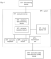
- Fig 4 shows a schematic example of a system according to an embodiment of the invention.
- the system 670 comprises a computer device 671 comprising a computer readable medium 672 and an electronic data processing device 673, such as a microprocessor.
- the system further comprises a visual display unit 676, a computer keyboard 674 and a computer mouse 675 for entering data and activating virtual buttons visualized on the visual display unit 676.
- the visual display unit 676 can be a computer screen.
- the computer device 671 is capable of providing a predetermined distance between neighbor denture teeth, when the user performs transformation of a denture tooth, e.g. by loading information into the electronic data processing device 673, and of executing one or more computer implemented algorithms using said electronic data processing device:
- the algorithms are configured for providing that the distance between neighbor teeth in the 3D arrangement of denture teeth is provided as the predetermined distance.
- the computer device 671 is further capable of receiving a digital 3D representation of the patient's upper and lower jaw, e.g. without any original teeth if the patient is edentulous, from a 3D scanning device 677, such as the TRIOS intra-oral scanner manufactured by 3shape TRIOS A/S, or capable of receiving scan data from such a 3D scanning device and forming a digital 3D representation of the patient's set of teeth based on such scan data.
- the received or formed digital 3D representation can be stored in the computer readable medium 672 and provided to the electronic data processing device 673.
- one or more options can be presented to the operator, such as which transformation should be performed, such as relocation, rotation etc, which denture tooth to transform, changing of different settings, such as the distance between the denture teeth after transformations.
- These options can be presented in a virtual environment visualized on the visual display unit 676.
- the system comprises a unit 678 for transmitting the final 3D arrangement of denture teeth after transformations to e.g. a computer aided manufacturing (CAM) device 679 for manufacturing the denture, e.g. the single denture teeth, the whole set of denture teeth, the artificial gingival etc. to another computer system e.g. located at a milling center where the denture teeth are manufactured or at a denture centre where the denture is assembled.
- the unit for transmitting can be a wired or a wireless connection.
- the 3D scanning of the patient's upper and lower jaw using the 3D scanning device 677 can be performed at a dentist while creating the denture at a dental laboratory.
- the digital 3D representation of the patient's upper and lower jaw can be provided via an internet connection between the dentist and the dental laboratory.
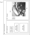
- Fig. 5 shows a schematic example of a virtual environment according to an embodiment of the invention.
- a first part 781 of the virtual environment 780 is seen in which an image 729 of the denture teeth provided with a predetermined distance between the denture teeth after the user's transformation.
- a virtual tool 782 can be used in marking or defining different features such as the denture tooth to be relocated.
- the virtual movement tool can be configured for grabbing the feature, e.g. the denture tooth and moving it in the virtual environment using e.g. a computer mouse.
- the second part 783 of the virtual environment comprises data entering sections 785, 786 for entering various data relevant for the procedure, such as data relating to what the distance between the denture teeth should be.
- a virtual push button 784 is configured for creating the relocation of neighbor denture teeth when the selected denture tooth is relocated.
- the virtual environment can be visualized on a visual display unit, such as a computer screen being part of a system configured for implementing the method according to the present invention.
- a claim may refer to any of the preceding claims, and "any” is understood to mean “any one or more” of the preceding claims.
- the features of the method described above and in the following may be implemented in software and carried out on a data processing system or other processing means caused by the execution of computer-executable instructions.
- the instructions may be program code means loaded in a memory, such as a RAM, from a storage medium or from another computer via a computer network.
- the described features may be implemented by hardwired circuitry instead of software or in combination with software.
Landscapes
- Health & Medical Sciences (AREA)
- Oral & Maxillofacial Surgery (AREA)
- Dentistry (AREA)
- Epidemiology (AREA)
- Life Sciences & Earth Sciences (AREA)
- Animal Behavior & Ethology (AREA)
- General Health & Medical Sciences (AREA)
- Public Health (AREA)
- Veterinary Medicine (AREA)
- Dental Tools And Instruments Or Auxiliary Dental Instruments (AREA)
Claims (14)
- Verfahren zum virtuellen/digitalen Gestalten einer Zahnprothese für einen Patienten, wobei die Zahnprothese eine Vielzahl von Zahnprothesenzähnen (202, 203 und 204) umfasst, wobei Gestalten der Zahnprothese Transformieren umfasst, wie Neuanordnen, Neupositionieren und/oder Drehen von Zahnprothesenzähnen der Zahnprothese, wobei das Verfahren Folgendes umfasst:- Erhalten eines 3D-Scans des Oberkiefers und Unterkiefers des Patienten;- Erhalten/Bereitstellen einer virtuellen 3D-Anordnung der Zahnprothesenzähne (202, 203 und 204), wobei die Zahnprothesenzähne in Okklusion voreingestellt sind;- virtuelles Anordnen/Bereitstellen des 3D-Scans des Oberkiefers und des Unterkiefers in Bezug auf die 3D-Anordnung der Zahnprothesenzähne (202, 203 und 204);- Definieren eines vorbestimmten Abstands zwischen mindestens einer Anzahl von benachbarten Zahnprothesenzähnen;- Bereitstellen des vorbestimmten Abstands zwischen den benachbarten Zahnprothesenzähnen, wenn der Benutzer einen Zahnprothesenzahn (202) in der virtuellen 3D-Anordnung der Zahnprothesenzähne virtuell neupositioniert, undwobei der virtuell neupositionierte Zahnprothesenzahn virtuell an einer angepassten Position zubeißt, wobei die angepassten Position eine Position des neupositionierten Zahns ist, an der der vorbestimmte Abstand zwischen Zähnen (202, 203 und 204) aufrechterhalten bleibt.
- Verfahren nach einem der vorstehenden Ansprüche, wobei einer oder mehrere der benachbarten Zahnprothesenzähne virtuell an einer angepassten Position zubeißen, wenn der Zahnprothesenzahn neupositioniert wird.
- Verfahren nach einer der vorstehenden Ausführungsformen, wobei die Zahnprothesenzähne in der virtuellen 3D-Anordnung von Zahnprothesenzähnen in drei logische Blöcke unterteilt werden, die die oberen und unteren Backenzähne sowie vorderen Backenzähne, die einen hinteren Block bilden, ein oberer anteriorer Zahnblock und ein unterer anteriorer Zahnblock sind.
- Verfahren nach einem der vorstehenden Ansprüche, wobei der vorbestimmte Abstand zwischen den Zähnen ausgewählt ist aus einer Gruppe, bestehend aus Folgendem:- der Abstand ist null, was in keinen Abstand zwischen den Zähnen resultiert, was bedeutet, dass die Zähne mit ihren proximalen Oberflächen so angeordnet sind, dass sie sich gegenseitig berühren;- der Abstand ist positiv, wodurch ein Abstand zwischen den Zähnen entsteht, d. h. ihre proximalen Oberflächen berühren sich nicht gegenseitig;- der Abstand ist negativ, was in Protrusion resultiert, was bedeutet, dass die Zähne einander überlappen.
- Verfahren nach einem der vorstehenden Ansprüche, wobei, wenn infolge der vom Benutzer durchgeführten Transformationen eine Lücke zwischen zwei benachbarten Zahnprothesenzähnen aufgetreten ist, der letzte Zahn mesial bewegt wird, wodurch die Lücke geschlossen wird, wobei sichergestellt wird, dass der vorbestimmte Abstand zwischen den Zähnen aufrechterhalten bleibt.
- Verfahren nach einem der vorstehenden Ansprüche, wobei, wenn ein tatsächlicher Abstand zwischen zwei benachbarten Zähnen der Zahnprothese geringer ist als der vorbestimmte Abstand, der letzte Zahn distal bewegt wird.
- Verfahren nach einem der vorstehenden Ansprüche, wobei die voreingestellte Okklusion ungeachtet der von den vom Benutzer durchgeführten Transformationen aufrechterhalten bleibt.
- Verfahren nach einem der vorstehenden Ansprüche, wobei das Verfahren weiter virtuelles Anordnen der 3D-Anordnung der Zahnprothesenzähne in Bezug auf einen Wachsabdruck des Patienten umfasst.
- Verfahren nach einem der vorstehenden Ansprüche, wobei das Verfahren weiter virtuelles Zubeißen der 3D-Anordnung der Zahnprothesenzähne auf dem Wachsabdruck umfasst.
- Verfahren nach einem der vorstehenden Ansprüche, wobei die Position der 3D-Anordnung der Zahnprothesenzähne in Bezug auf den Wachsabdruck durch Berechnen des Mindestabstands zwischen einem vordefinierten Gesichts-/Vestibulärpunkt von jedem Zahn und dem Wachsabdruck bestimmt wird.
- Computerprogrammprodukt, das Programmcodemittel umfasst, um zu bewirken, dass ein Datenverarbeitungssystem das Verfahren nach einem oder mehreren der vorstehenden Ansprüche durchführt, wenn die Programmcodemittel von dem Datenverarbeitungssystem ausgeführt werden, und Computerprogrammprodukt, das ein computerlesbares Medium umfasst, das darauf die Programmcodemittel gespeichert hat.
- System (607) zum virtuelle Gestalten einer Zahnprothese für einen Patienten, wobei die Zahnprothese eine Vielzahl von Zahnprothesenzähnen umfasst, wobei Gestalten der Zahnprothese Transformieren umfasst, wie Neuanordnen, Neupositionieren und/oder Drehen von Zahnprothesenzähnen der Zahnprothese, wobei das Verfahren Folgendes umfasst:- Mittel zum Erhalten eines 3D-Scans des Oberkiefers und Unterkiefers des Patienten;- Mittel zum Erhalten/Bereitstellen einer virtuellen 3D-Anordnung der Zahnprothesenzähne, wobei die Zahnprothesenzähne in Okklusion voreingestellt sind;- Mittel zum virtuellen Anordnen/Bereitstellen des 3D-Scans des Oberkiefers und des Unterkiefers in Bezug auf die 3D-Anordnung der Zahnprothesenzähne;- Mittel zum Definieren eines vorbestimmten Abstands zwischen mindestens einer Anzahl von benachbarten Zahnprothesenzähnen;- Mittel zum Bereitstellen des vorbestimmten Abstands zwischen den benachbarten Zahnprothesenzähnen, wenn der Benutzer einen Zahnprothesenzahn in der virtuellen 3D-Anordnung der Zahnprothesenzähne virtuell neupositioniert, und- Mittel zum virtuellen Zubeißen des virtuell neupositionierten Zahnprothesenzahns an einer angepassten Position, wobei die angepasste Position eine Position des neupositionierten Zahns ist, wobei der vorbestimmte Abstand zwischen Zähnen aufrechterhalten bleibt.
- System nach Anspruch 12, wobei das System ein nichtflüchtiges computerlesbares Medium umfasst, auf dem eine oder mehrere Computeranweisungen gespeichert sind, wobei die Computeranweisungen Anweisungen zum Ausführen eines Verfahrens zum virtuellen Gestalten einer Zahnprothese für einen Patienten umfassen, wobei die Zahnprothese eine Vielzahl von Zahnprothesenzähnen umfasst, wobei Gestalten der Zahnprothese Transformieren umfasst, wie Neuanordnen, Neupositionieren und/oder Drehen von Zahnprothesenzähnen der Zahnprothese, wobei das Verfahren Folgendes umfasst:- Erhalten eines 3D-Scans des Oberkiefers und Unterkiefers des Patienten;- Erhalten/Bereitstellen einer virtuellen 3D-Anordnung der Zahnprothesenzähne, wobei die Zahnprothesenzähne in Okklusion voreingestellt sind;- virtuelles Anordnen/Bereitstellen des 3D-Scans des Oberkiefers und des Unterkiefers in Bezug auf die 3D-Anordnung der Zahnprothesenzähne;- Definieren eines vorbestimmten Abstands zwischen mindestens einer Anzahl von benachbarten Zahnprothesenzähnen;- Bereitstellen des vorbestimmten Abstands zwischen den benachbarten Zahnprothesenzähnen, wenn der Benutzer einen Zahnprothesenzahn in der virtuellen 3D-Anordnung der Zahnprothesenzähne virtuell neupositioniert.
- Virtuelle Gestaltungsumgebung (780) zum Gestalten einer Zahnprothese für einen Patienten, wobei die Zahnprothese eine Vielzahl von Zahnprothesenzähnen umfasst, wobei Gestalten der Zahnprothese Transformieren umfasst, wie Neuanordnen, Neupositionieren und/oder Drehen von Zahnprothesenzähnen der Zahnprothese, wobei die virtuelle Gestaltungsumgebung Folgendes umfasst:- einen virtuellen Arbeitsbereich, der zum Visualisieren eines 3D-Scans des Oberkiefers und Unterkiefers des Patienten und zum Visualisieren einer virtuellen 3D-Anordnung der Zahnprothesenzähne, wobei die Zahnprothesenzähne in Okklusion voreingestellt sind, angepasst ist;- ein virtuelles Anordnungswerkzeug zum Anordnen oder Bereitstellen des 3D-Scans des Oberkiefers und Unterkiefers in Bezug auf die 3D-Anordnung der Zahnprothesenzähne;- ein virtuelles Definitionswerkzeug zum Definieren eines vorbestimmten Abstands zwischen mindestens einer Anzahl von benachbarten Zahnprothesenzähnen;- ein virtuelles Werkzeug zum Bereitstellen des vorbestimmten Abstands zwischen den benachbarten Zahnprothesenzähnen, wenn der Benutzer einen Zahnprothesenzahn in der virtuellen 3D-Anordnung der Zahnprothesenzähne virtuell neupositioniert, wobei der neupositionierte Zahnprothesenzahn virtuell an einer angepassten Position zubeißt, wobei die angepasste Position eine Position des neupositionierten Zahns ist, an der der vorbestimmte Abstand zwischen Zähnen aufrechterhalten bleibt.
Priority Applications (2)
| Application Number | Priority Date | Filing Date | Title |
|---|---|---|---|
| EP23192771.6A EP4268766B1 (de) | 2013-12-20 | 2014-12-19 | Methode, computerprogramm, system, und virtuelles designumfeld zur digitalen konzipierung eines gebisses für einen patienten |
| EP25170531.5A EP4563119A3 (de) | 2013-12-20 | 2014-12-19 | Einrasten von zahnprothesenzähnen |
Applications Claiming Priority (3)
| Application Number | Priority Date | Filing Date | Title |
|---|---|---|---|
| DKPA201370802 | 2013-12-20 | ||
| PCT/EP2014/078832 WO2015092000A1 (en) | 2013-12-20 | 2014-12-19 | Snapping of denture teeth |
| EP14821627.8A EP3082642B1 (de) | 2013-12-20 | 2014-12-19 | Einrastender zahnersatz |
Related Parent Applications (2)
| Application Number | Title | Priority Date | Filing Date |
|---|---|---|---|
| PCT/EP2014/078832 Previously-Filed-Application WO2015092000A1 (en) | 2013-12-20 | 2014-12-19 | Snapping of denture teeth |
| EP14821627.8A Division EP3082642B1 (de) | 2013-12-20 | 2014-12-19 | Einrastender zahnersatz |
Related Child Applications (3)
| Application Number | Title | Priority Date | Filing Date |
|---|---|---|---|
| EP25170531.5A Division EP4563119A3 (de) | 2013-12-20 | 2014-12-19 | Einrasten von zahnprothesenzähnen |
| EP23192771.6A Division EP4268766B1 (de) | 2013-12-20 | 2014-12-19 | Methode, computerprogramm, system, und virtuelles designumfeld zur digitalen konzipierung eines gebisses für einen patienten |
| EP23192771.6A Previously-Filed-Application EP4268766B1 (de) | 2013-12-20 | 2014-12-19 | Methode, computerprogramm, system, und virtuelles designumfeld zur digitalen konzipierung eines gebisses für einen patienten |
Publications (2)
| Publication Number | Publication Date |
|---|---|
| EP3954323A1 EP3954323A1 (de) | 2022-02-16 |
| EP3954323B1 true EP3954323B1 (de) | 2023-08-23 |
Family
ID=52278632
Family Applications (4)
| Application Number | Title | Priority Date | Filing Date |
|---|---|---|---|
| EP14821627.8A Active EP3082642B1 (de) | 2013-12-20 | 2014-12-19 | Einrastender zahnersatz |
| EP21184425.3A Active EP3954323B1 (de) | 2013-12-20 | 2014-12-19 | Methode, computer program, system, und virtueler design umfeld zur digitalen konzipierung eines gebisses für einen patienten |
| EP23192771.6A Active EP4268766B1 (de) | 2013-12-20 | 2014-12-19 | Methode, computerprogramm, system, und virtuelles designumfeld zur digitalen konzipierung eines gebisses für einen patienten |
| EP25170531.5A Pending EP4563119A3 (de) | 2013-12-20 | 2014-12-19 | Einrasten von zahnprothesenzähnen |
Family Applications Before (1)
| Application Number | Title | Priority Date | Filing Date |
|---|---|---|---|
| EP14821627.8A Active EP3082642B1 (de) | 2013-12-20 | 2014-12-19 | Einrastender zahnersatz |
Family Applications After (2)
| Application Number | Title | Priority Date | Filing Date |
|---|---|---|---|
| EP23192771.6A Active EP4268766B1 (de) | 2013-12-20 | 2014-12-19 | Methode, computerprogramm, system, und virtuelles designumfeld zur digitalen konzipierung eines gebisses für einen patienten |
| EP25170531.5A Pending EP4563119A3 (de) | 2013-12-20 | 2014-12-19 | Einrasten von zahnprothesenzähnen |
Country Status (5)
| Country | Link |
|---|---|
| US (3) | US11083550B2 (de) |
| EP (4) | EP3082642B1 (de) |
| DK (1) | DK3082642T3 (de) |
| ES (2) | ES2895940T3 (de) |
| WO (1) | WO2015092000A1 (de) |
Families Citing this family (4)
| Publication number | Priority date | Publication date | Assignee | Title |
|---|---|---|---|---|
| US10327867B2 (en) | 2015-02-25 | 2019-06-25 | James R. Glidewell Dental Ceramics, Inc. | Arch form placement for dental restoration design |
| US11351014B2 (en) | 2018-06-01 | 2022-06-07 | Dentsply Sirona Inc. | Methods of digitally designing artificial teeth |
| CN109223216A (zh) * | 2018-09-27 | 2019-01-18 | 北京大学口腔医学院 | 一种可摘局部义齿的高效率数字设计方法 |
| DK3705080T3 (da) * | 2019-03-08 | 2021-08-23 | Exocad Gmbh | Computerimplementeret modellering af en patientindividuel tandprotesedel |
Family Cites Families (13)
| Publication number | Priority date | Publication date | Assignee | Title |
|---|---|---|---|---|
| JPH09238959A (ja) * | 1996-03-11 | 1997-09-16 | G C:Kk | 総義歯作製方法 |
| US6783360B2 (en) * | 2000-12-13 | 2004-08-31 | Align Technology, Inc. | Systems and methods for positioning teeth |
| DE10304757B4 (de) * | 2003-02-05 | 2005-07-21 | Heraeus Kulzer Gmbh | Vorrichtung und Verfahren zur Herstellung von Zahnersatz |
| US7993133B2 (en) | 2006-10-20 | 2011-08-09 | 3M Innovative Properties Company | Digital orthodontic treatment planning |
| EP3085330B1 (de) | 2006-10-27 | 2018-06-13 | Nobel Biocare Services AG | Verfahren und vorrichtung zur gewinnung von daten für eine zahnkomponente und ein physikalisches gebissmodell |
| GB0707454D0 (en) * | 2007-04-18 | 2007-05-23 | Materialise Dental Nv | Computer-assisted creation of a custom tooth set-up using facial analysis |
| BRPI1009891B8 (pt) * | 2009-03-20 | 2021-06-22 | 3Shape As | sistema e método para planejamento, visualização e otimização de restaurações dentárias |
| US20110318709A1 (en) * | 2010-06-25 | 2011-12-29 | Takeshi Moriyama | Artificial tooth |
| WO2012021816A2 (en) * | 2010-08-13 | 2012-02-16 | Sensable Technologies, Inc. | Systems for denture preparation |
| EP3777757B1 (de) | 2010-10-01 | 2024-02-14 | 3Shape A/S | Modellierung und herstellung von zahnersatz |
| DK3473204T3 (da) * | 2011-11-28 | 2020-10-26 | 3Shape As | Tandpræpareringsguide |
| WO2013120955A1 (en) | 2012-02-14 | 2013-08-22 | 3Shape A/S | Modeling a digital design of a denture |
| AU2013276501B2 (en) * | 2012-06-15 | 2017-01-19 | Vita Zahnfabrik H. Rauter Gmbh & Co. Kg | Method for preparing a partial or full dental prosthesis |
-
2014
- 2014-12-19 US US15/103,082 patent/US11083550B2/en active Active
- 2014-12-19 EP EP14821627.8A patent/EP3082642B1/de active Active
- 2014-12-19 DK DK14821627.8T patent/DK3082642T3/da active
- 2014-12-19 EP EP21184425.3A patent/EP3954323B1/de active Active
- 2014-12-19 ES ES14821627T patent/ES2895940T3/es active Active
- 2014-12-19 ES ES21184425T patent/ES2965359T3/es active Active
- 2014-12-19 EP EP23192771.6A patent/EP4268766B1/de active Active
- 2014-12-19 WO PCT/EP2014/078832 patent/WO2015092000A1/en not_active Ceased
- 2014-12-19 EP EP25170531.5A patent/EP4563119A3/de active Pending
-
2021
- 2021-05-27 US US17/332,412 patent/US12426998B2/en active Active
-
2025
- 2025-09-04 US US19/319,400 patent/US20260069386A1/en active Pending
Also Published As
| Publication number | Publication date |
|---|---|
| EP4268766A3 (de) | 2023-12-06 |
| EP3082642A1 (de) | 2016-10-26 |
| DK3082642T3 (da) | 2021-11-15 |
| EP3954323A1 (de) | 2022-02-16 |
| EP4563119A2 (de) | 2025-06-04 |
| ES2965359T3 (es) | 2024-04-15 |
| EP4563119A3 (de) | 2025-08-13 |
| WO2015092000A1 (en) | 2015-06-25 |
| US20160310244A1 (en) | 2016-10-27 |
| EP4268766B1 (de) | 2025-04-30 |
| EP4268766A2 (de) | 2023-11-01 |
| US20260069386A1 (en) | 2026-03-12 |
| US20210282905A1 (en) | 2021-09-16 |
| US11083550B2 (en) | 2021-08-10 |
| US12426998B2 (en) | 2025-09-30 |
| ES2895940T3 (es) | 2022-02-23 |
| EP3082642B1 (de) | 2021-08-04 |
Similar Documents
| Publication | Publication Date | Title |
|---|---|---|
| US12426998B2 (en) | Snapping of denture teeth | |
| US10952817B1 (en) | Systems and methods for determining orthodontic treatments | |
| US11751975B2 (en) | Systems and methods for determining a jaw curve | |
| CN111631831B (zh) | 生成牙科矫正器的方法 | |
| CN108024841B (zh) | 牙齿建模系统 | |
| JP6757671B2 (ja) | 歯肉モデルの仮想二次加工方法 | |
| US10945811B1 (en) | Systems and methods for determining orthodontic treatments | |
| US11517400B1 (en) | Systems and methods for determining a position for an orthodontic attachment | |
| EP3212119A1 (de) | Verfahren, system und benutzerschnittstelle zur erstellung eines digitalen entwurfs zur verwendung bei der herstellung einer formschale für einen zahnersatz | |
| US12514684B2 (en) | Patient specific appliance design | |
| US12285310B2 (en) | Methods and systems for determining occlusal contacts between teeth of a subject | |
| US20240033045A1 (en) | Systems and methods for occlusal mandibular advancement block placement | |
| CN116585055A (zh) | 一种不同弹性模量隐形牙套的效果分析方法、系统及设备 | |
| US11801122B1 (en) | System and a method for determining a tooth T-marking | |
| EP3718498B1 (de) | Systeme und verfahren zur herstellung einer kieferorthopädischen ausrichtungsvorrichtung | |
| WO2026066633A1 (zh) | 一种矫治设计方案的生成方法、电子设备及存储介质 |
Legal Events
| Date | Code | Title | Description |
|---|---|---|---|
| PUAI | Public reference made under article 153(3) epc to a published international application that has entered the european phase |
Free format text: ORIGINAL CODE: 0009012 |
|
| STAA | Information on the status of an ep patent application or granted ep patent |
Free format text: STATUS: THE APPLICATION HAS BEEN PUBLISHED |
|
| AC | Divisional application: reference to earlier application |
Ref document number: 3082642 Country of ref document: EP Kind code of ref document: P |
|
| AK | Designated contracting states |
Kind code of ref document: A1 Designated state(s): AL AT BE BG CH CY CZ DE DK EE ES FI FR GB GR HR HU IE IS IT LI LT LU LV MC MK MT NL NO PL PT RO RS SE SI SK SM TR |
|
| STAA | Information on the status of an ep patent application or granted ep patent |
Free format text: STATUS: REQUEST FOR EXAMINATION WAS MADE |
|
| 17P | Request for examination filed |
Effective date: 20220815 |
|
| RBV | Designated contracting states (corrected) |
Designated state(s): AL AT BE BG CH CY CZ DE DK EE ES FI FR GB GR HR HU IE IS IT LI LT LU LV MC MK MT NL NO PL PT RO RS SE SI SK SM TR |
|
| GRAP | Despatch of communication of intention to grant a patent |
Free format text: ORIGINAL CODE: EPIDOSNIGR1 |
|
| STAA | Information on the status of an ep patent application or granted ep patent |
Free format text: STATUS: GRANT OF PATENT IS INTENDED |
|
| RIC1 | Information provided on ipc code assigned before grant |
Ipc: A61C 11/00 20060101ALN20230207BHEP Ipc: A61C 13/01 20060101ALI20230207BHEP Ipc: A61C 13/34 20060101ALI20230207BHEP Ipc: A61C 13/00 20060101AFI20230207BHEP |
|
| INTG | Intention to grant announced |
Effective date: 20230309 |
|
| GRAS | Grant fee paid |
Free format text: ORIGINAL CODE: EPIDOSNIGR3 |
|
| GRAA | (expected) grant |
Free format text: ORIGINAL CODE: 0009210 |
|
| STAA | Information on the status of an ep patent application or granted ep patent |
Free format text: STATUS: THE PATENT HAS BEEN GRANTED |
|
| AC | Divisional application: reference to earlier application |
Ref document number: 3082642 Country of ref document: EP Kind code of ref document: P |
|
| AK | Designated contracting states |
Kind code of ref document: B1 Designated state(s): AL AT BE BG CH CY CZ DE DK EE ES FI FR GB GR HR HU IE IS IT LI LT LU LV MC MK MT NL NO PL PT RO RS SE SI SK SM TR |
|
| REG | Reference to a national code |
Ref country code: GB Ref legal event code: FG4D |
|
| REG | Reference to a national code |
Ref country code: CH Ref legal event code: EP |
|
| REG | Reference to a national code |
Ref country code: DE Ref legal event code: R096 Ref document number: 602014088089 Country of ref document: DE |
|
| REG | Reference to a national code |
Ref country code: IE Ref legal event code: FG4D |
|
| P01 | Opt-out of the competence of the unified patent court (upc) registered |
Effective date: 20230822 |
|
| REG | Reference to a national code |
Ref country code: LT Ref legal event code: MG9D |
|
| REG | Reference to a national code |
Ref country code: NL Ref legal event code: MP Effective date: 20230823 |
|
| REG | Reference to a national code |
Ref country code: AT Ref legal event code: MK05 Ref document number: 1601685 Country of ref document: AT Kind code of ref document: T Effective date: 20230823 |
|
| PG25 | Lapsed in a contracting state [announced via postgrant information from national office to epo] |
Ref country code: GR Free format text: LAPSE BECAUSE OF FAILURE TO SUBMIT A TRANSLATION OF THE DESCRIPTION OR TO PAY THE FEE WITHIN THE PRESCRIBED TIME-LIMIT Effective date: 20231124 |
|
| PG25 | Lapsed in a contracting state [announced via postgrant information from national office to epo] |
Ref country code: IS Free format text: LAPSE BECAUSE OF FAILURE TO SUBMIT A TRANSLATION OF THE DESCRIPTION OR TO PAY THE FEE WITHIN THE PRESCRIBED TIME-LIMIT Effective date: 20231223 |
|
| PG25 | Lapsed in a contracting state [announced via postgrant information from national office to epo] |
Ref country code: SE Free format text: LAPSE BECAUSE OF FAILURE TO SUBMIT A TRANSLATION OF THE DESCRIPTION OR TO PAY THE FEE WITHIN THE PRESCRIBED TIME-LIMIT Effective date: 20230823 Ref country code: RS Free format text: LAPSE BECAUSE OF FAILURE TO SUBMIT A TRANSLATION OF THE DESCRIPTION OR TO PAY THE FEE WITHIN THE PRESCRIBED TIME-LIMIT Effective date: 20230823 Ref country code: PT Free format text: LAPSE BECAUSE OF FAILURE TO SUBMIT A TRANSLATION OF THE DESCRIPTION OR TO PAY THE FEE WITHIN THE PRESCRIBED TIME-LIMIT Effective date: 20231226 Ref country code: NO Free format text: LAPSE BECAUSE OF FAILURE TO SUBMIT A TRANSLATION OF THE DESCRIPTION OR TO PAY THE FEE WITHIN THE PRESCRIBED TIME-LIMIT Effective date: 20231123 Ref country code: NL Free format text: LAPSE BECAUSE OF FAILURE TO SUBMIT A TRANSLATION OF THE DESCRIPTION OR TO PAY THE FEE WITHIN THE PRESCRIBED TIME-LIMIT Effective date: 20230823 Ref country code: LV Free format text: LAPSE BECAUSE OF FAILURE TO SUBMIT A TRANSLATION OF THE DESCRIPTION OR TO PAY THE FEE WITHIN THE PRESCRIBED TIME-LIMIT Effective date: 20230823 Ref country code: LT Free format text: LAPSE BECAUSE OF FAILURE TO SUBMIT A TRANSLATION OF THE DESCRIPTION OR TO PAY THE FEE WITHIN THE PRESCRIBED TIME-LIMIT Effective date: 20230823 Ref country code: IS Free format text: LAPSE BECAUSE OF FAILURE TO SUBMIT A TRANSLATION OF THE DESCRIPTION OR TO PAY THE FEE WITHIN THE PRESCRIBED TIME-LIMIT Effective date: 20231223 Ref country code: HR Free format text: LAPSE BECAUSE OF FAILURE TO SUBMIT A TRANSLATION OF THE DESCRIPTION OR TO PAY THE FEE WITHIN THE PRESCRIBED TIME-LIMIT Effective date: 20230823 Ref country code: GR Free format text: LAPSE BECAUSE OF FAILURE TO SUBMIT A TRANSLATION OF THE DESCRIPTION OR TO PAY THE FEE WITHIN THE PRESCRIBED TIME-LIMIT Effective date: 20231124 Ref country code: FI Free format text: LAPSE BECAUSE OF FAILURE TO SUBMIT A TRANSLATION OF THE DESCRIPTION OR TO PAY THE FEE WITHIN THE PRESCRIBED TIME-LIMIT Effective date: 20230823 Ref country code: AT Free format text: LAPSE BECAUSE OF FAILURE TO SUBMIT A TRANSLATION OF THE DESCRIPTION OR TO PAY THE FEE WITHIN THE PRESCRIBED TIME-LIMIT Effective date: 20230823 |
|
| PG25 | Lapsed in a contracting state [announced via postgrant information from national office to epo] |
Ref country code: PL Free format text: LAPSE BECAUSE OF FAILURE TO SUBMIT A TRANSLATION OF THE DESCRIPTION OR TO PAY THE FEE WITHIN THE PRESCRIBED TIME-LIMIT Effective date: 20230823 |
|
| REG | Reference to a national code |
Ref country code: ES Ref legal event code: FG2A Ref document number: 2965359 Country of ref document: ES Kind code of ref document: T3 Effective date: 20240415 |
|
| PG25 | Lapsed in a contracting state [announced via postgrant information from national office to epo] |
Ref country code: SM Free format text: LAPSE BECAUSE OF FAILURE TO SUBMIT A TRANSLATION OF THE DESCRIPTION OR TO PAY THE FEE WITHIN THE PRESCRIBED TIME-LIMIT Effective date: 20230823 Ref country code: RO Free format text: LAPSE BECAUSE OF FAILURE TO SUBMIT A TRANSLATION OF THE DESCRIPTION OR TO PAY THE FEE WITHIN THE PRESCRIBED TIME-LIMIT Effective date: 20230823 Ref country code: EE Free format text: LAPSE BECAUSE OF FAILURE TO SUBMIT A TRANSLATION OF THE DESCRIPTION OR TO PAY THE FEE WITHIN THE PRESCRIBED TIME-LIMIT Effective date: 20230823 Ref country code: DK Free format text: LAPSE BECAUSE OF FAILURE TO SUBMIT A TRANSLATION OF THE DESCRIPTION OR TO PAY THE FEE WITHIN THE PRESCRIBED TIME-LIMIT Effective date: 20230823 Ref country code: CZ Free format text: LAPSE BECAUSE OF FAILURE TO SUBMIT A TRANSLATION OF THE DESCRIPTION OR TO PAY THE FEE WITHIN THE PRESCRIBED TIME-LIMIT Effective date: 20230823 Ref country code: SK Free format text: LAPSE BECAUSE OF FAILURE TO SUBMIT A TRANSLATION OF THE DESCRIPTION OR TO PAY THE FEE WITHIN THE PRESCRIBED TIME-LIMIT Effective date: 20230823 |
|
| REG | Reference to a national code |
Ref country code: DE Ref legal event code: R097 Ref document number: 602014088089 Country of ref document: DE |
|
| PLBE | No opposition filed within time limit |
Free format text: ORIGINAL CODE: 0009261 |
|
| STAA | Information on the status of an ep patent application or granted ep patent |
Free format text: STATUS: NO OPPOSITION FILED WITHIN TIME LIMIT |
|
| 26N | No opposition filed |
Effective date: 20240524 |
|
| PG25 | Lapsed in a contracting state [announced via postgrant information from national office to epo] |
Ref country code: SI Free format text: LAPSE BECAUSE OF FAILURE TO SUBMIT A TRANSLATION OF THE DESCRIPTION OR TO PAY THE FEE WITHIN THE PRESCRIBED TIME-LIMIT Effective date: 20230823 |
|
| REG | Reference to a national code |
Ref country code: CH Ref legal event code: PL |
|
| PG25 | Lapsed in a contracting state [announced via postgrant information from national office to epo] |
Ref country code: LU Free format text: LAPSE BECAUSE OF NON-PAYMENT OF DUE FEES Effective date: 20231219 |
|
| PG25 | Lapsed in a contracting state [announced via postgrant information from national office to epo] |
Ref country code: MC Free format text: LAPSE BECAUSE OF FAILURE TO SUBMIT A TRANSLATION OF THE DESCRIPTION OR TO PAY THE FEE WITHIN THE PRESCRIBED TIME-LIMIT Effective date: 20230823 |
|
| REG | Reference to a national code |
Ref country code: BE Ref legal event code: MM Effective date: 20231231 |
|
| PG25 | Lapsed in a contracting state [announced via postgrant information from national office to epo] |
Ref country code: MC Free format text: LAPSE BECAUSE OF FAILURE TO SUBMIT A TRANSLATION OF THE DESCRIPTION OR TO PAY THE FEE WITHIN THE PRESCRIBED TIME-LIMIT Effective date: 20230823 Ref country code: LU Free format text: LAPSE BECAUSE OF NON-PAYMENT OF DUE FEES Effective date: 20231219 |
|
| REG | Reference to a national code |
Ref country code: IE Ref legal event code: MM4A |
|
| PG25 | Lapsed in a contracting state [announced via postgrant information from national office to epo] |
Ref country code: IE Free format text: LAPSE BECAUSE OF NON-PAYMENT OF DUE FEES Effective date: 20231219 |
|
| PG25 | Lapsed in a contracting state [announced via postgrant information from national office to epo] |
Ref country code: BE Free format text: LAPSE BECAUSE OF NON-PAYMENT OF DUE FEES Effective date: 20231231 |
|
| PG25 | Lapsed in a contracting state [announced via postgrant information from national office to epo] |
Ref country code: CH Free format text: LAPSE BECAUSE OF NON-PAYMENT OF DUE FEES Effective date: 20231231 |
|
| PG25 | Lapsed in a contracting state [announced via postgrant information from national office to epo] |
Ref country code: IE Free format text: LAPSE BECAUSE OF NON-PAYMENT OF DUE FEES Effective date: 20231219 Ref country code: CH Free format text: LAPSE BECAUSE OF NON-PAYMENT OF DUE FEES Effective date: 20231231 Ref country code: BE Free format text: LAPSE BECAUSE OF NON-PAYMENT OF DUE FEES Effective date: 20231231 |
|
| PG25 | Lapsed in a contracting state [announced via postgrant information from national office to epo] |
Ref country code: BG Free format text: LAPSE BECAUSE OF FAILURE TO SUBMIT A TRANSLATION OF THE DESCRIPTION OR TO PAY THE FEE WITHIN THE PRESCRIBED TIME-LIMIT Effective date: 20230823 |
|
| PG25 | Lapsed in a contracting state [announced via postgrant information from national office to epo] |
Ref country code: BG Free format text: LAPSE BECAUSE OF FAILURE TO SUBMIT A TRANSLATION OF THE DESCRIPTION OR TO PAY THE FEE WITHIN THE PRESCRIBED TIME-LIMIT Effective date: 20230823 |
|
| PG25 | Lapsed in a contracting state [announced via postgrant information from national office to epo] |
Ref country code: CY Free format text: LAPSE BECAUSE OF FAILURE TO SUBMIT A TRANSLATION OF THE DESCRIPTION OR TO PAY THE FEE WITHIN THE PRESCRIBED TIME-LIMIT; INVALID AB INITIO Effective date: 20141219 |
|
| PG25 | Lapsed in a contracting state [announced via postgrant information from national office to epo] |
Ref country code: HU Free format text: LAPSE BECAUSE OF FAILURE TO SUBMIT A TRANSLATION OF THE DESCRIPTION OR TO PAY THE FEE WITHIN THE PRESCRIBED TIME-LIMIT; INVALID AB INITIO Effective date: 20141219 |
|
| PG25 | Lapsed in a contracting state [announced via postgrant information from national office to epo] |
Ref country code: TR Free format text: LAPSE BECAUSE OF FAILURE TO SUBMIT A TRANSLATION OF THE DESCRIPTION OR TO PAY THE FEE WITHIN THE PRESCRIBED TIME-LIMIT Effective date: 20230823 |
|
| PGFP | Annual fee paid to national office [announced via postgrant information from national office to epo] |
Ref country code: DE Payment date: 20251211 Year of fee payment: 12 |
|
| PGFP | Annual fee paid to national office [announced via postgrant information from national office to epo] |
Ref country code: GB Payment date: 20251219 Year of fee payment: 12 |
|
| PGFP | Annual fee paid to national office [announced via postgrant information from national office to epo] |
Ref country code: IT Payment date: 20251223 Year of fee payment: 12 |
|
| PGFP | Annual fee paid to national office [announced via postgrant information from national office to epo] |
Ref country code: FR Payment date: 20251229 Year of fee payment: 12 |
|
| PGFP | Annual fee paid to national office [announced via postgrant information from national office to epo] |
Ref country code: ES Payment date: 20260130 Year of fee payment: 12 |