EP3954331A1 - Verbindungsstruktur zwischen stent und klappensegel und interventionelle klappe-in-klappe und interventionelle aortenklappe mit der verbindungsstruktur - Google Patents
Verbindungsstruktur zwischen stent und klappensegel und interventionelle klappe-in-klappe und interventionelle aortenklappe mit der verbindungsstruktur Download PDFInfo
- Publication number
- EP3954331A1 EP3954331A1 EP20788292.9A EP20788292A EP3954331A1 EP 3954331 A1 EP3954331 A1 EP 3954331A1 EP 20788292 A EP20788292 A EP 20788292A EP 3954331 A1 EP3954331 A1 EP 3954331A1
- Authority
- EP
- European Patent Office
- Prior art keywords
- valve
- stent
- supporting rods
- interventional
- row
- Prior art date
- Legal status (The legal status is an assumption and is not a legal conclusion. Google has not performed a legal analysis and makes no representation as to the accuracy of the status listed.)
- Withdrawn
Links
Images


Classifications
-
- A—HUMAN NECESSITIES
- A61—MEDICAL OR VETERINARY SCIENCE; HYGIENE
- A61F—FILTERS IMPLANTABLE INTO BLOOD VESSELS; PROSTHESES; DEVICES PROVIDING PATENCY TO, OR PREVENTING COLLAPSING OF, TUBULAR STRUCTURES OF THE BODY, e.g. STENTS; ORTHOPAEDIC, NURSING OR CONTRACEPTIVE DEVICES; FOMENTATION; TREATMENT OR PROTECTION OF EYES OR EARS; BANDAGES, DRESSINGS OR ABSORBENT PADS; FIRST-AID KITS
- A61F2/00—Filters implantable into blood vessels; Prostheses, i.e. artificial substitutes or replacements for parts of the body; Appliances for connecting them with the body; Devices providing patency to, or preventing collapsing of, tubular structures of the body, e.g. stents
- A61F2/02—Prostheses implantable into the body
- A61F2/24—Heart valves ; Vascular valves, e.g. venous valves; Heart implants, e.g. passive devices for improving the function of the native valve or the heart muscle; Transmyocardial revascularisation [TMR] devices; Valves implantable in the body
- A61F2/2412—Heart valves ; Vascular valves, e.g. venous valves; Heart implants, e.g. passive devices for improving the function of the native valve or the heart muscle; Transmyocardial revascularisation [TMR] devices; Valves implantable in the body with soft flexible valve members, e.g. tissue valves shaped like natural valves
- A61F2/2418—Scaffolds therefor, e.g. support stents
-
- A—HUMAN NECESSITIES
- A61—MEDICAL OR VETERINARY SCIENCE; HYGIENE
- A61F—FILTERS IMPLANTABLE INTO BLOOD VESSELS; PROSTHESES; DEVICES PROVIDING PATENCY TO, OR PREVENTING COLLAPSING OF, TUBULAR STRUCTURES OF THE BODY, e.g. STENTS; ORTHOPAEDIC, NURSING OR CONTRACEPTIVE DEVICES; FOMENTATION; TREATMENT OR PROTECTION OF EYES OR EARS; BANDAGES, DRESSINGS OR ABSORBENT PADS; FIRST-AID KITS
- A61F2/00—Filters implantable into blood vessels; Prostheses, i.e. artificial substitutes or replacements for parts of the body; Appliances for connecting them with the body; Devices providing patency to, or preventing collapsing of, tubular structures of the body, e.g. stents
- A61F2/02—Prostheses implantable into the body
- A61F2/24—Heart valves ; Vascular valves, e.g. venous valves; Heart implants, e.g. passive devices for improving the function of the native valve or the heart muscle; Transmyocardial revascularisation [TMR] devices; Valves implantable in the body
- A61F2/2427—Devices for manipulating or deploying heart valves during implantation
- A61F2/243—Deployment by mechanical expansion
- A61F2/2433—Deployment by mechanical expansion using balloon catheter
-
- A—HUMAN NECESSITIES
- A61—MEDICAL OR VETERINARY SCIENCE; HYGIENE
- A61F—FILTERS IMPLANTABLE INTO BLOOD VESSELS; PROSTHESES; DEVICES PROVIDING PATENCY TO, OR PREVENTING COLLAPSING OF, TUBULAR STRUCTURES OF THE BODY, e.g. STENTS; ORTHOPAEDIC, NURSING OR CONTRACEPTIVE DEVICES; FOMENTATION; TREATMENT OR PROTECTION OF EYES OR EARS; BANDAGES, DRESSINGS OR ABSORBENT PADS; FIRST-AID KITS
- A61F2/00—Filters implantable into blood vessels; Prostheses, i.e. artificial substitutes or replacements for parts of the body; Appliances for connecting them with the body; Devices providing patency to, or preventing collapsing of, tubular structures of the body, e.g. stents
- A61F2/02—Prostheses implantable into the body
- A61F2/24—Heart valves ; Vascular valves, e.g. venous valves; Heart implants, e.g. passive devices for improving the function of the native valve or the heart muscle; Transmyocardial revascularisation [TMR] devices; Valves implantable in the body
- A61F2/2442—Annuloplasty rings or inserts for correcting the valve shape; Implants for improving the function of a native heart valve
- A61F2/2463—Implants forming part of the valve leaflets
-
- A—HUMAN NECESSITIES
- A61—MEDICAL OR VETERINARY SCIENCE; HYGIENE
- A61F—FILTERS IMPLANTABLE INTO BLOOD VESSELS; PROSTHESES; DEVICES PROVIDING PATENCY TO, OR PREVENTING COLLAPSING OF, TUBULAR STRUCTURES OF THE BODY, e.g. STENTS; ORTHOPAEDIC, NURSING OR CONTRACEPTIVE DEVICES; FOMENTATION; TREATMENT OR PROTECTION OF EYES OR EARS; BANDAGES, DRESSINGS OR ABSORBENT PADS; FIRST-AID KITS
- A61F2220/00—Fixations or connections for prostheses classified in groups A61F2/00 - A61F2/26 or A61F2/82 or A61F9/00 or A61F11/00 or subgroups thereof
- A61F2220/0025—Connections or couplings between prosthetic parts, e.g. between modular parts; Connecting elements
- A61F2220/0075—Connections or couplings between prosthetic parts, e.g. between modular parts; Connecting elements sutured, ligatured or stitched, retained or tied with a rope, string, thread, wire or cable
-
- A—HUMAN NECESSITIES
- A61—MEDICAL OR VETERINARY SCIENCE; HYGIENE
- A61F—FILTERS IMPLANTABLE INTO BLOOD VESSELS; PROSTHESES; DEVICES PROVIDING PATENCY TO, OR PREVENTING COLLAPSING OF, TUBULAR STRUCTURES OF THE BODY, e.g. STENTS; ORTHOPAEDIC, NURSING OR CONTRACEPTIVE DEVICES; FOMENTATION; TREATMENT OR PROTECTION OF EYES OR EARS; BANDAGES, DRESSINGS OR ABSORBENT PADS; FIRST-AID KITS
- A61F2230/00—Geometry of prostheses classified in groups A61F2/00 - A61F2/26 or A61F2/82 or A61F9/00 or A61F11/00 or subgroups thereof
- A61F2230/0002—Two-dimensional shapes, e.g. cross-sections
- A61F2230/0028—Shapes in the form of latin or greek characters
- A61F2230/0054—V-shaped
Definitions
- the invention relates to the technical field of medical instruments, in particular to a connecting structure of a stent and a valve leaflet for interventional valve-in-valve or interventional aortic valve, and an interventional valve-in-valve and an interventional aortic valve applying the connecting structure.
- Interventional valve-in-valve is a special re-interventional therapy for patients who can't undergo surgical valve replacement after valve destruction of previously implanted (interventional) artificial bioprosthetic heart valves for various reasons. That is, the interventional valve-in-valve is placed into the artificial bioprosthetic valve which has failed through the catheter to replace the failed bioprosthetic valve to achieve the purpose of treatment.
- the age of patients with surgical implants of biological valves should be reduced to 50, and for patients of any age, bioprosthetic valve are recommended for contraindicated, inappropriate or undesirable anticoagulant therapy.
- the artificial bioprosthetic valve for aortic valve replacement in the elderly will increase year by year, and for those elderly and severe patients who cannot undergo valve replacement surgery, re-interventional therapy through the valve-in-the-valve will become the hope of final treatment. Having an interventional valve-in-valve with the same durability as a surgical bioprosthetic valve will be a sharp weapon for these patients to be treated again.
- the technical problem to be solved by the present invention is to provide a connecting structure of a stent and valve leaflet for interventional valve-in-valve or interventional aortic valve, and an interventional valve-in-valve and an interventional aortic valve using the connecting structure, wherein a cushioning portion is arranged on the inner side of a metal stent, so that the valve leaflets can be prevented from being in direct contact with the stent, and the service durability of a valve product is improved.
- the technical scheme adopted by the invention is to provide a connecting structure of a stent and valve leaflets for an interventional valve-in-valve or an interventional aortic valve, wherein the stent is a metal mesh tube, the valve leaflets are three fan-shaped valve leaflets arranged on the inner side of the stent, each of the three fan-shaped valve leaflets is provided with a free edge, an arc-shaped bottom edge and valve leaflet junction connecting parts extending on two sides, and three connecting posts are uniformly distributed on the metal mesh tube, each connecting post is at least provided with a rectangular slit, the junction connecting part of the fan-shaped valve leaflets comprises a radial overturning connecting part and an axial overturning connecting part, the radial overturning connecting part of each fan-shaped valve leaflet penetrates through the rectangular slit of the connecting post to penetrate from the inner side to the outer side then folds, the axial overturning connecting part is folded on the inner side of the connecting post to forms a cushioning portion, and then is connected
- the radial overturning connecting parts of the two adjacent valve leaflets junction connecting parts are connected through a flexible connecting piece in a suturing mode, then penetrate through the rectangular slit of the connecting post, and are fixed with the connecting post through a suture after clamping and fixing with a rigid gasket on the inner side of the flexible connecting piece.
- holes or rectangular frames are symmetrically arranged on two sides of the rectangular slit on each connecting post, the number of the holes is four to eight, and the number of the rectangular frames is two or four.
- the material of the stent is an implantable alloy material
- the implantable alloy material is a cobalt-based alloy, a nickel-titanium alloy or a stainless steel material
- the material of the valve leaflet is an animal-derived tissue material or a medical polymer material.
- the invention also provides an interventional valve-in-valve or an interventional aortic valve applying the above connecting structure, which comprises a sent that can be radially compressible and in a slightly flaring shape after being expanded by a balloon, three fan-shaped valve leaflets arranged on the inner side of the stent, the three fan-shaped valve leaflets are respectively provided with a free edge, an arc-shaped bottom edge and valve leaflet junction connecting parts extending on the two sides, the stent is a metal mesh tube, and three connecting posts are uniformly distributed on the metal mesh tube; each connecting post is at least provided with a rectangular slit, the junction connecting part of the fan-shaped valve leaflets comprises a radial overturning connecting part and an axial overturning connecting part, and the radial overturning connecting part of each fan-shaped valve leaflet penetrates through the rectangular slit of the connecting post and penetrates from the inner side to the outer side then folds; and the axial overturning connecting part is folded at the inner side of the connecting post to form
- the radial overturning connecting parts of the two adjacent valve leaflets junction connecting parts are connected through a flexible connecting piece in a suturing mode, then penetrate through the rectangular slit of the connecting post, and are fixed with the connecting post through a suture after clamping and fixing with a rigid gasket on the inner side of the flexible connecting piece.
- holes or rectangular frames are symmetrically arranged on two sides of the rectangular slit on each connecting post, the number of the holes is four to eight, and the number of the rectangular frames is two or four.
- the material of the stent is an implantable alloy material
- the implantable alloy material is a cobalt-based alloy, a nickel-titanium alloy or a stainless steel material
- the material of the valve leaflet is an animal-derived tissue material or a medical polymer material.
- the stent is provided with a plurality of columns of axial supporting rods arranged between the connecting posts, three rows of transversely extending circumferential supporting rods are arranged between the connecting posts and the axial supporting rods, the lower first row of circumferential supporting rods define the inflow end of the stent, the second row of circumferential supporting rods and the third row of circumferential supporting rods spaced from the first row define an outflow end of the stent, and each row of circumferential supporting rods consists of a plurality of groups of angular supporting rods connected together; each group of supporting rods is in the shape of a deformable V, the deformation angle is 0-90 degrees, each group of circumferential supporting rods in the first row and the second row are arranged in parallel and opposite to the direction of each group of circumferential supporting rods in the third row, and a coating membrane on the body wall of the stent is sewn between the first row of circumferential supporting rods and the second row of circumferential supporting rods
- the stent is provided with four rows of transversely extending circumferential supporting rods and a plurality of columns of axial supporting rods arranged between the circumferential supporting rods, wherein the lower first and second row of circumferential supporting rods define the inflow end of the stent, the third and fourth row of circumferential supporting rods define the outflow end of the stent, each row of circumferential supporting rods consists of a plurality of groups of angular supporting rods connected together, and each group of supporting rods is in a deformable V shape; the deformation angle is 0-90 degrees, a plurality of columns of axial supporting rods and a plurality of groups of circumferential supporting rods are mutually connected to form a honeycomb space, and a coating membrane on the body wall of the stent is sewn between the first row of circumferential supporting rods and the third row of circumferential supporting rods.
- a coating membrane is sewn between the first row of circumferential supporting rods and the second row of circumferential supporting rods outside the body wall of the stent.
- the angle between the outer edge of the balloon-expanded stent and its axis is between 0° and 30°.
- the invention has the beneficial effects that: the invention provides a connecting structure of a stent and valve leaflets for interventional valve-in-valve or interventional aortic valve, and an interventional valve-in-valve and an interventional aortic valve applying the connecting structure.
- the valve leaflets Due to the fact that the animal-derived tissue material is folded at the inner side of the valve leaflet junction connection tissue to form a cushioning portion, and then the cushioning portion is connected and fixed on the connecting post of the stent through sutures, the valve leaflets can be prevented from being rubbed or scratched by the metal stent in the opening and closing processes; and due to the fact that the connecting posts in the connecting structure are double rows of holes or rectangular frame routing, the sutures at the seams of the junction connecting parts of the valve leaflets are fully fixed with the holes or the rectangular frame, stress concentration of the valve leaflets in the opening and closing processes can be avoided, use durability of the interventional valve-in-valve or the interventional aortic valve is improved, and a durable effect equivalent to that of a surgical valve is achieved.
- the interventional valve-in-valve in the present invention refers to the accumulation of research and clinical application of the artificial bioprosthetic heart valve for more than 50 years, and under the same condition of the bioprosthetic valve chemical modification technology, the structural design of the interventional valve, the connection and fixation between the valve leaflet boundary tissues and he connection and fixation of the valve leaflet tissues and the set structure of the stent are realized, so that the requirements of hydromechanics and valve firmness of valve during opening and closing are met.
- the present invention provides a connecting structure of a stent and a valve leaflet for an interventional valve-in-valve or an interventional aortic valve, and an interventional valve-in-valve and an interventional aortic valve using the connecting structure.
- the interventional valve-in-valve has a "lower” end and an “upper” end.
- the terms “lower” and “upper” are used interchangeably with the terms “inflow” and “outflow”, respectively.
- the lower end of the interventional valve-in-valve is its inflow end and the upper end of the interventional valve-in-valve is its outflow end.
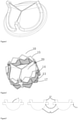
- FIG. 2 there is shown a schematic view of an interventional valve-in-valve structure for re-interventional therapy of an artificial bioprosthetic heart valve according to an example of the present invention, comprising a stent 10 that can be radially compressible and in a slightly flaring shape after being expanded by a balloon (referring to FIG. 7 ), three fan-shaped valve leaflets 20 arranged on the inner side of the stent 10, the three fan-shaped valve leaflets 20 are respectively provided with a free edge 21, an arc-shaped bottom edge 22 and valve leaflet junction connecting parts 23 extending on the two sides (referring to FIG. 3 ).
- FIG. 7 a schematic view of an interventional valve-in-valve structure for re-interventional therapy of an artificial bioprosthetic heart valve according to an example of the present invention, comprising a stent 10 that can be radially compressible and in a slightly flaring shape after being expanded by a balloon (referring to FIG. 7 ), three fan-shaped valve leaflets 20 arranged on the inner side of the
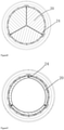
- the stent is a metal mesh tube, wherein three connecting posts 11 are uniformly distributed on the metal mesh tube, six columns of axial supporting rods 12 are uniformly distributed among the three connecting posts 11, three rows of circumferential supporting rods 13, 14 and 15 transversely penetrating and extending are arranged between the connecting posts 11 and the six columns of axial supporting rods 12, and the lower first row of circumferential supporting rods 13 defines the inflow end of the stent 10, the second row of circumferential supporting rods 14 and the third row of circumferential supporting rods 15 spaced from the first row of circumferential supporting rods 13 define the outflow end of the stent.
- Each row of circumferential supporting rods is formed by connecting supporting rods EE with multiple constituent angles, each group of supporting rods EE is in the shape of a deformable V, the deformation angle is 0-90 degrees, and each group of circumferential supporting rods of the first row of circumferential supporting rods 13 and the second row of circumferential supporting rods 14 are arranged in parallel and opposite to the direction of each group of circumferential supporting rods of the third row of circumferential supporting rods 15 to form a plurality of grids which can be synchronously deformed.
- the stent made of the metal mesh tube can adapt to a use mode that an interventional valve-in-valve is longitudinally compressed and then expanded during interventional therapy.
- the connecting post 11 is provided with a rectangular slit 18, two rows of six holes 16 are symmetrically formed in two sides of the rectangular slit 18 for fixedly connecting the fan-shaped valve leaflets through sutures.
- a coating membrane 17 is sewn between the first row of circumferential supporting rods 13 and the second row of circumferential supporting rods 14.
- the coating membrane on the body wall of the stent is sewn between the first row of circumferential supporting rods and the third row of circumferential supporting rods.
- an outside coating membrane (not shown) is further sewn to the outside at the same location as desired.
- the material of the coating membrane can be animal-derived tissues or medical polymer materials which would occur to a person skilled in the art.
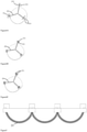
- the junction connecting part 23 of the fan-shaped valve leaflet 20 includes two portions: a radial overturning connecting part 231 and an axial overturning connecting part 232, wherein the radial overturning connecting part 231 is aligned in pairs at first, and then penetrates the rectangular slit 18 from the inner side of the connecting column 11 to be opened and folded, and fixes to the connecting column through sutures, the axial overturning connecting part 232 is then folded down on the inside of the connecting post in the opposite direction to fit and align with the fan-shaped valve leaflets 20 by using sutures, such that a section of cushioning portion 24 is formed at the root of the free edge of the fan-shaped valve leaflet, and the cushioning portion 24 is further secured to the hole 16 of connecting post 11 of the stent by sutures.
- the radial overturning connecting part may be re-fixed to the extent necessary to overturn to wrap around the connecting post 11.
- the arc-shaped bottom edge of the fan-shaped valve leaflet can also be coated with a reinforced coating membrane 25, and the coating membrane further sewn on the body wall of the stent through the coating membrane 25.
- the valve leaflets of the interventional valve-in-valve when the valve leaflets of the interventional valve-in-valve are opened, due to the existence of the cushioning portion 24, the valve leaflets can be prevented from being rubbed or scratched by the metal stent in the opening and closing processes; and due to the fact that the connecting posts in the connecting structure are double rows of holes routing, the sutures at the seams of the junction connecting parts of the valve leaflets are fully fixed with the holes or the rectangular frame, stress concentration of the valve leaflets in the opening and closing processes can be avoided, use durability of the interventional valve-in-valve or the interventional aortic valve is improved, and a durable effect equivalent to that of a surgical valve is achieved.
- the interventional valve-in-valve of the present invention can be used for the re-interventional therapy of the interventional valve in addition to the re-interventional therapy of the surgical valve in this example.
- Example 2 interventional aortic valve
- the structure of the present invention can be directly used for the interventional therapy of the aortic valve in addition to the re-interventional therapy in Example 1.
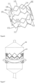
- the interventional aortic valve of the example has a stent structure different from that of Example 1, and other structures are substantially the same as those of Example 1. In some cases, a larger outflow end and a larger stent height are required. Referring to FIGS.
- the stent 50 is a metal mesh tube having three connecting posts 51 evenly distributed thereon, the stent is provided with four rows of transversely extending circumferential supporting rods 52, 53, 54 and 55, and a plurality of axial supporting rods 56 arranged between the circumferential supporting rods, wherein the lower first and second row of circumferential supporting rods 52, 53 define the inflow end of the stent, the third and fourth row of circumferential supporting rods 54, 55 define the outflow end of the stent, each row of circumferential supporting rods consists of a plurality of groups of angular supporting rods EE connected together, and each group of supporting rods is in a deformable V shape; the deformation angle is 0-90 degrees, the plurality of columns of axial supporting rods 56 and a plurality of groups of circumferential supporting rods are mutually connected to form a deformable honeycomb grid.
- the cellular grid in which the outflow end is defined is larger.
- the upper portion of the connecting post 11 is provided with a rectangular slit 59, two rows of rectangular frames 57 are symmetrically arranged on two sides of the slit, in the example, after the axial overturning connecting parts of the adjacent fan-shaped valve leaflets are aligned, the adjacent fan-shaped valve leaflets firstly pass through the rectangular slit 59, then are opened to pass through the two rectangular frames 57 respectively, followed by being overturned again to cover the outer sides of the connecting post, and are fixed to the connecting post through sutures, so as to improve the connection strength of valve leaflet and stent.
- a coating membrane 58 is sewn between the first row of circumferential supporting rods 52 and the third row of circumferential supporting rods 54.
- an outer coating membrane (not shown) is also sewn to the outside of the coating membrane between the first row of circumferential supporting rods 52 and the second row of circumferential supporting rods 53, as desired.
- the material of the coating membrane can be animal-derived tissues or medical polymer materials which would occur to a person skilled in the art.
- valve leaflets 80 are fixedly connected to the stent 70, the connecting post 71 of the stent 70 has only one slit 72, a flexible connecting piece 90 is sewn between the axial overturning connecting part 81 of the two adjacent valve leaflets junction, penetrates through the rectangular slit 72, then the reinforcing gasket 91 is placed, and is fully fixedly connected to the connecting post through sutures to enclosed into a whole.
- the radial overturning connecting part of the valve leaflets may take the same way as in the previous examples.
- the stent in all examples may be implemented as, but is not limited to, a cobalt-based alloy or nickel-titanium alloy or stainless steel material or other implantable alloy material stent or the like, and is not specifically limited thereto;
- the valve leaflet is an animal-derived tissue material or a medical polymer material, for example, any one of a porcine pericardium, a bovine pericardium or a sheep pericardium tissue material or any one of medical polymer materials, and is not specifically limited thereto.
- the suture is any one of medical polymer materials.
Landscapes
- Health & Medical Sciences (AREA)
- Cardiology (AREA)
- Engineering & Computer Science (AREA)
- Biomedical Technology (AREA)
- Oral & Maxillofacial Surgery (AREA)
- Transplantation (AREA)
- Heart & Thoracic Surgery (AREA)
- Vascular Medicine (AREA)
- Life Sciences & Earth Sciences (AREA)
- Animal Behavior & Ethology (AREA)
- General Health & Medical Sciences (AREA)
- Public Health (AREA)
- Veterinary Medicine (AREA)
- Mechanical Engineering (AREA)
- Prostheses (AREA)
Applications Claiming Priority (2)
| Application Number | Priority Date | Filing Date | Title |
|---|---|---|---|
| CN201910274761.9A CN109984870A (zh) | 2019-04-08 | 2019-04-08 | 一种支架和瓣叶的连接结构及应用该连接结构的介入瓣中瓣和介入主动脉瓣 |
| PCT/CN2020/083088 WO2020207332A1 (zh) | 2019-04-08 | 2020-04-03 | 一种支架和瓣叶的连接结构及应用该连接结构的介入瓣中瓣和介入主动脉瓣 |
Publications (2)
| Publication Number | Publication Date |
|---|---|
| EP3954331A1 true EP3954331A1 (de) | 2022-02-16 |
| EP3954331A4 EP3954331A4 (de) | 2022-06-08 |
Family
ID=67131213
Family Applications (1)
| Application Number | Title | Priority Date | Filing Date |
|---|---|---|---|
| EP20788292.9A Withdrawn EP3954331A4 (de) | 2019-04-08 | 2020-04-03 | Verbindungsstruktur zwischen stent und klappensegel und interventionelle klappe-in-klappe und interventionelle aortenklappe mit der verbindungsstruktur |
Country Status (6)
| Country | Link |
|---|---|
| US (1) | US20220160503A1 (de) |
| EP (1) | EP3954331A4 (de) |
| JP (1) | JP2022528091A (de) |
| CN (1) | CN109984870A (de) |
| SG (1) | SG11202111140QA (de) |
| WO (1) | WO2020207332A1 (de) |
Families Citing this family (8)
| Publication number | Priority date | Publication date | Assignee | Title |
|---|---|---|---|---|
| CN109984870A (zh) * | 2019-04-08 | 2019-07-09 | 北京佰仁医疗科技股份有限公司 | 一种支架和瓣叶的连接结构及应用该连接结构的介入瓣中瓣和介入主动脉瓣 |
| CN110507451B (zh) * | 2019-08-29 | 2025-11-18 | 上海翰凌医疗器械有限公司 | 瓣膜支架及具有其的人工瓣膜 |
| CN112826637A (zh) * | 2019-11-22 | 2021-05-25 | 上海微创心通医疗科技有限公司 | 一种心脏瓣膜假体 |
| CN111184596A (zh) * | 2020-02-18 | 2020-05-22 | 科凯(南通)生命科学有限公司 | 一种人工心脏瓣膜 |
| CN113729830A (zh) * | 2021-09-27 | 2021-12-03 | 启晨(上海)医疗器械有限公司 | 气道阻塞装置 |
| CN119868009B (zh) * | 2023-10-25 | 2025-10-10 | 上海臻亿医疗科技有限公司 | 人工瓣膜支架及人工瓣膜假体 |
| WO2025188285A1 (en) * | 2024-03-08 | 2025-09-12 | Erzi̇ncan Bi̇nali̇ Yildirim Üni̇versi̇tesi̇ Rektörlüğü Genel Sekreterli̇k | Clamped aortic valve |
| CN118021494B (zh) * | 2024-04-15 | 2024-07-12 | 上海欣吉特生物科技有限公司 | 一种瓣中瓣支架及瓣膜 |
Family Cites Families (22)
| Publication number | Priority date | Publication date | Assignee | Title |
|---|---|---|---|---|
| US6454799B1 (en) * | 2000-04-06 | 2002-09-24 | Edwards Lifesciences Corporation | Minimally-invasive heart valves and methods of use |
| US6936067B2 (en) * | 2001-05-17 | 2005-08-30 | St. Jude Medical Inc. | Prosthetic heart valve with slit stent |
| EP1753374A4 (de) * | 2004-04-23 | 2010-02-10 | 3F Therapeutics Inc | Implantierbares protheseventil |
| US8062359B2 (en) * | 2005-04-06 | 2011-11-22 | Edwards Lifesciences Corporation | Highly flexible heart valve connecting band |
| EP1991168B1 (de) * | 2006-02-16 | 2016-01-27 | Transcatheter Technologies GmbH | Minimalinvasiver herzklappenersatz |
| US8425593B2 (en) * | 2007-09-26 | 2013-04-23 | St. Jude Medical, Inc. | Collapsible prosthetic heart valves |
| EP2254513B1 (de) * | 2008-01-24 | 2015-10-28 | Medtronic, Inc. | Stents für herzklappenprothesen |
| CA3272239A1 (en) * | 2008-06-06 | 2025-10-28 | Edwards Lifesciences Corporation | Low profile transcatheter heart valve |
| JP5603934B2 (ja) * | 2009-06-05 | 2014-10-08 | メドトロニック エイティーエス メディカル インコーポレイテッド | 生体補綴弁を取り付けるための可撓性交連構造 |
| CA3020195C (en) * | 2010-10-05 | 2020-10-27 | Edwards Lifesciences Corporation | Prosthetic heart valve |
| CN107496054B (zh) * | 2011-06-21 | 2020-03-03 | 托尔福公司 | 人工心脏瓣膜装置及相关系统和方法 |
| EP4049625B1 (de) * | 2011-12-09 | 2025-01-08 | Edwards Lifesciences Corporation | Herzklappenprothese mit verbesserten kommissurstützen |
| US20140005776A1 (en) * | 2012-06-29 | 2014-01-02 | St. Jude Medical, Cardiology Division, Inc. | Leaflet attachment for function in various shapes and sizes |
| US10098734B2 (en) * | 2013-12-05 | 2018-10-16 | Edwards Lifesciences Corporation | Prosthetic heart valve and delivery apparatus |
| US10195025B2 (en) * | 2014-05-12 | 2019-02-05 | Edwards Lifesciences Corporation | Prosthetic heart valve |
| US10987216B2 (en) * | 2015-12-15 | 2021-04-27 | Meril Life Sciences Pvt Ltd | Prosthetic valve |
| US11135056B2 (en) * | 2017-05-15 | 2021-10-05 | Edwards Lifesciences Corporation | Devices and methods of commissure formation for prosthetic heart valve |
| US11147667B2 (en) * | 2017-09-08 | 2021-10-19 | Edwards Lifesciences Corporation | Sealing member for prosthetic heart valve |
| US20190091013A1 (en) * | 2017-09-22 | 2019-03-28 | St. Jude Medical, Cardiology Division, Inc. | Prosthetic Heart Valve with Atraumatic Aortic Portion |
| EP3687451B1 (de) * | 2017-09-27 | 2023-12-13 | Edwards Lifesciences Corporation | Herzklappenprothese mit erweiterbarem rahmen |
| CN210541937U (zh) * | 2019-04-08 | 2020-05-19 | 北京佰仁医疗科技股份有限公司 | 一种支架和瓣叶的连接结构及应用该连接结构的介入瓣中瓣和介入主动脉瓣 |
| CN109984870A (zh) * | 2019-04-08 | 2019-07-09 | 北京佰仁医疗科技股份有限公司 | 一种支架和瓣叶的连接结构及应用该连接结构的介入瓣中瓣和介入主动脉瓣 |
-
2019
- 2019-04-08 CN CN201910274761.9A patent/CN109984870A/zh active Pending
-
2020
- 2020-04-03 JP JP2021558007A patent/JP2022528091A/ja active Pending
- 2020-04-03 SG SG11202111140QA patent/SG11202111140QA/en unknown
- 2020-04-03 WO PCT/CN2020/083088 patent/WO2020207332A1/zh not_active Ceased
- 2020-04-03 US US17/602,711 patent/US20220160503A1/en not_active Abandoned
- 2020-04-03 EP EP20788292.9A patent/EP3954331A4/de not_active Withdrawn
Also Published As
| Publication number | Publication date |
|---|---|
| SG11202111140QA (en) | 2021-11-29 |
| US20220160503A1 (en) | 2022-05-26 |
| JP2022528091A (ja) | 2022-06-08 |
| CN109984870A (zh) | 2019-07-09 |
| WO2020207332A1 (zh) | 2020-10-15 |
| EP3954331A4 (de) | 2022-06-08 |
Similar Documents
| Publication | Publication Date | Title |
|---|---|---|
| EP3954331A1 (de) | Verbindungsstruktur zwischen stent und klappensegel und interventionelle klappe-in-klappe und interventionelle aortenklappe mit der verbindungsstruktur | |
| US10463484B2 (en) | Prosthetic heart valve having leaflet inflow below frame | |
| US11395734B2 (en) | Prosthetic valve and prosthetic valve implanting method | |
| CN202105047U (zh) | 小外形经导管的心瓣膜 | |
| US20250186201A1 (en) | Interventional aortic valve | |
| US20190388221A1 (en) | Artificial heart valve | |
| CN210541937U (zh) | 一种支架和瓣叶的连接结构及应用该连接结构的介入瓣中瓣和介入主动脉瓣 | |
| EP3668455A1 (de) | Entwurf eines herzklappenrahmens mit ungleichförmigen streben | |
| CN210541936U (zh) | 一种支架和瓣叶的连接结构及应用该连接结构的介入肺动脉瓣和介入主动脉瓣 | |
| HK40010103B (en) | Low profile transcatheter heart valve | |
| HK40010103A (en) | Low profile transcatheter heart valve | |
| HK40007805B (en) | Low profile transcatheter heart valve | |
| HK40007805A (en) | Low profile transcatheter heart valve | |
| HK40007992B (en) | Low profile transcatheter heart valve | |
| HK40007992A (en) | Low profile transcatheter heart valve |
Legal Events
| Date | Code | Title | Description |
|---|---|---|---|
| STAA | Information on the status of an ep patent application or granted ep patent |
Free format text: STATUS: THE INTERNATIONAL PUBLICATION HAS BEEN MADE |
|
| PUAI | Public reference made under article 153(3) epc to a published international application that has entered the european phase |
Free format text: ORIGINAL CODE: 0009012 |
|
| STAA | Information on the status of an ep patent application or granted ep patent |
Free format text: STATUS: REQUEST FOR EXAMINATION WAS MADE |
|
| 17P | Request for examination filed |
Effective date: 20211101 |
|
| AK | Designated contracting states |
Kind code of ref document: A1 Designated state(s): AL AT BE BG CH CY CZ DE DK EE ES FI FR GB GR HR HU IE IS IT LI LT LU LV MC MK MT NL NO PL PT RO RS SE SI SK SM TR |
|
| A4 | Supplementary search report drawn up and despatched |
Effective date: 20220509 |
|
| RIC1 | Information provided on ipc code assigned before grant |
Ipc: A61F 2/24 20060101AFI20220502BHEP |
|
| DAV | Request for validation of the european patent (deleted) | ||
| DAX | Request for extension of the european patent (deleted) | ||
| STAA | Information on the status of an ep patent application or granted ep patent |
Free format text: STATUS: EXAMINATION IS IN PROGRESS |
|
| 17Q | First examination report despatched |
Effective date: 20241008 |
|
| STAA | Information on the status of an ep patent application or granted ep patent |
Free format text: STATUS: THE APPLICATION IS DEEMED TO BE WITHDRAWN |
|
| 18D | Application deemed to be withdrawn |
Effective date: 20250211 |