EP3954533A1 - Dispositif et procédé de coupe pour la bavure d'un pneu - Google Patents
Dispositif et procédé de coupe pour la bavure d'un pneu Download PDFInfo
- Publication number
- EP3954533A1 EP3954533A1 EP21187634.7A EP21187634A EP3954533A1 EP 3954533 A1 EP3954533 A1 EP 3954533A1 EP 21187634 A EP21187634 A EP 21187634A EP 3954533 A1 EP3954533 A1 EP 3954533A1
- Authority
- EP
- European Patent Office
- Prior art keywords
- cutting
- tire
- tool
- flash
- robotic arm
- Prior art date
- Legal status (The legal status is an assumption and is not a legal conclusion. Google has not performed a legal analysis and makes no representation as to the accuracy of the status listed.)
- Granted
Links
Images





Classifications
-
- B—PERFORMING OPERATIONS; TRANSPORTING
- B26—HAND CUTTING TOOLS; CUTTING; SEVERING
- B26D—CUTTING; DETAILS COMMON TO MACHINES FOR PERFORATING, PUNCHING, CUTTING-OUT, STAMPING-OUT OR SEVERING
- B26D3/00—Cutting work characterised by the nature of the cut made; Apparatus therefor
- B26D3/003—Cutting work characterised by the nature of the cut made; Apparatus therefor specially adapted for cutting rubber
-
- B—PERFORMING OPERATIONS; TRANSPORTING
- B25—HAND TOOLS; PORTABLE POWER-DRIVEN TOOLS; MANIPULATORS
- B25J—MANIPULATORS; CHAMBERS PROVIDED WITH MANIPULATION DEVICES
- B25J11/00—Manipulators not otherwise provided for
- B25J11/005—Manipulators for mechanical processing tasks
- B25J11/006—Deburring or trimming
-
- B—PERFORMING OPERATIONS; TRANSPORTING
- B26—HAND CUTTING TOOLS; CUTTING; SEVERING
- B26D—CUTTING; DETAILS COMMON TO MACHINES FOR PERFORATING, PUNCHING, CUTTING-OUT, STAMPING-OUT OR SEVERING
- B26D1/00—Cutting through work characterised by the nature or movement of the cutting member or particular materials not otherwise provided for; Apparatus or machines therefor; Cutting members therefor
- B26D1/0006—Cutting members therefor
-
- B—PERFORMING OPERATIONS; TRANSPORTING
- B26—HAND CUTTING TOOLS; CUTTING; SEVERING
- B26D—CUTTING; DETAILS COMMON TO MACHINES FOR PERFORATING, PUNCHING, CUTTING-OUT, STAMPING-OUT OR SEVERING
- B26D3/00—Cutting work characterised by the nature of the cut made; Apparatus therefor
- B26D3/28—Splitting layers from work; Mutually separating layers by cutting
-
- B—PERFORMING OPERATIONS; TRANSPORTING
- B26—HAND CUTTING TOOLS; CUTTING; SEVERING
- B26D—CUTTING; DETAILS COMMON TO MACHINES FOR PERFORATING, PUNCHING, CUTTING-OUT, STAMPING-OUT OR SEVERING
- B26D7/00—Details of apparatus for cutting, cutting-out, stamping-out, punching, perforating, or severing by means other than cutting
- B26D7/26—Means for mounting or adjusting the cutting member; Means for adjusting the stroke of the cutting member
- B26D7/2614—Means for mounting the cutting member
-
- B—PERFORMING OPERATIONS; TRANSPORTING
- B29—WORKING OF PLASTICS; WORKING OF SUBSTANCES IN A PLASTIC STATE IN GENERAL
- B29D—PRODUCING PARTICULAR ARTICLES FROM PLASTICS OR FROM SUBSTANCES IN A PLASTIC STATE
- B29D30/00—Producing pneumatic or solid tyres or parts thereof
- B29D30/06—Pneumatic tyres or parts thereof (e.g. produced by casting, moulding, compression moulding, injection moulding, centrifugal casting)
- B29D30/0601—Vulcanising tyres; Vulcanising presses for tyres
- B29D30/0633—After-treatment specially adapted for vulcanising tyres
-
- B—PERFORMING OPERATIONS; TRANSPORTING
- B26—HAND CUTTING TOOLS; CUTTING; SEVERING
- B26D—CUTTING; DETAILS COMMON TO MACHINES FOR PERFORATING, PUNCHING, CUTTING-OUT, STAMPING-OUT OR SEVERING
- B26D1/00—Cutting through work characterised by the nature or movement of the cutting member or particular materials not otherwise provided for; Apparatus or machines therefor; Cutting members therefor
- B26D1/0006—Cutting members therefor
- B26D2001/0033—Cutting members therefor assembled from multiple blades
-
- B—PERFORMING OPERATIONS; TRANSPORTING
- B26—HAND CUTTING TOOLS; CUTTING; SEVERING
- B26D—CUTTING; DETAILS COMMON TO MACHINES FOR PERFORATING, PUNCHING, CUTTING-OUT, STAMPING-OUT OR SEVERING
- B26D1/00—Cutting through work characterised by the nature or movement of the cutting member or particular materials not otherwise provided for; Apparatus or machines therefor; Cutting members therefor
- B26D1/0006—Cutting members therefor
- B26D2001/006—Cutting members therefor the cutting blade having a special shape, e.g. a special outline, serrations
-
- B—PERFORMING OPERATIONS; TRANSPORTING
- B29—WORKING OF PLASTICS; WORKING OF SUBSTANCES IN A PLASTIC STATE IN GENERAL
- B29D—PRODUCING PARTICULAR ARTICLES FROM PLASTICS OR FROM SUBSTANCES IN A PLASTIC STATE
- B29D30/00—Producing pneumatic or solid tyres or parts thereof
- B29D30/06—Pneumatic tyres or parts thereof (e.g. produced by casting, moulding, compression moulding, injection moulding, centrifugal casting)
- B29D30/0601—Vulcanising tyres; Vulcanising presses for tyres
- B29D30/0633—After-treatment specially adapted for vulcanising tyres
- B29D2030/0634—Measuring, calculating, correcting tyre uniformity, e.g. correcting RFV
- B29D2030/0638—Correcting by removing material, e.g. by grinding
Definitions
- the present description relates to a tire trimming tool.
- it relates to a tool and related procedure for trimming tire flashes that allows for effective removal of excess rubber components resulting from the tire's vulcanization process.
- the curing molds for tires have a large number of small-diameter passages that allow air to escape either from the entire tire structure or between the mold and the green tire to be cured. After vulcanization, these channels are partially filled with rubber, leaving this excess rubber on the tire surface. In addition to this excess rubber on the tire surface, there is additional excess material on the tire bead.
- the excess rubber, called tire burr must be removed to reduce noise emissions and ensure a good fit of the tire on the rim to prevent air leakage.
- the procedure for removing tire burrs generally consists of rotating the tire on a machine and manually removing this excess rubber using a V-shaped moving blade.
- the document US10011054 describes a cutting tool for trimming a tread of a tire, including a cutting plate having a plurality of cutting slits formed sequentially at a lower end to cut off excess rubber (burrs) formed on the tread of a tire, and a handle attached to the cutting plate and provided for the user to hold said tool for cutting said excess rubber.
- the cutting plate has a variety of on the Grooves formed on the back to guide and discharge the cut rubber vertically through the cutting slots.
- the document CN108515650 describes a deburring device for a sidewall of a tire.
- the device consists of two symmetrical sets of cutting tools for the left and right side, an assembly of a driving structure, a tire and a ball screw.
- the cutting units are installed on the driving structure assembly and are placed on both sides of the tire; the opening and closing movement driven by the ball screw is performed on the assembly of the running structure to control the distance from the side surface of the tire.
- the document CH598003 describes a cutting tool.
- the tool consists of cutting elements located radially along the sidewall of the rotating tires.
- the cutting elements have cutting blades with edges that contact the sidewalls of the tire to remove the excess polymer (burrs).
- the device consists of a pair of arm-mounted cutting tools that move radially along the sidewalls of the tires.
- the arms move along the side walls and are controlled by antennas.
- the tires are driven by three rollers distributed around the circumference and guided laterally by two transversal register rollers.
- the document CN105014848 describes an automatic cutting device for a tire.
- the device consists of a frame of the cutting machine, a mechanism for positioning the cut, as well as a rotating mechanism and scraper assemblies.
- the trimmer positioning mechanism, rotating mechanism and scraper assemblies are all mounted on the trimmer frame.
- the scraper assemblies are used to trim the tire surface and both sides of the tire.
- the document CN106671325 describes a production line for deburring the tire surface that includes a roller axle transport line and a plurality of deburring stations.
- the multiple deburring stations are sequentially arranged along the roller axis transport line.
- Each deburring station consists of a rotating bulge, with at least one deburring manipulator still positioned on the outside of the rotating bulge.
- Each deburring manipulator has two torsion springs that are arranged symmetrically on a frame.
- Each torsion spring is connected to the first end of a torque arm; the second end of each torque arm is connected to one end of a cuttershaft arm; the other ends of both knife shaft arms are connected by a knife shaft; a plurality of cutter heads are sequentially superimposed in the axial direction of the cutter shaft; and the running wheels are still located at the top and bottom of the knife shaft.
- the torsional force is applied by the torsion springs, the cutter shaft is firmly attached to the side surface of a tire by a certain tension, the fact that the cutter shaft deburring tools always contact with the side surface of the tire ensures that the deburring tools can do the deburring work.
- the document GB1495209 relates to a trimmer for removing excess molten polymer on a tire, comprising a tire support assembly in which a tire is received for rotation about its axis and a cutting assembly having cutting tools mounted for movement along tire surfaces .
- Each cutting tool has one or more contoured edges to conform to tire surfaces and one or more guide rollers in the cutting area to guide the cutting tool in conjunction with a tire to be trimmed.
- the cutters of the tire sidewall trimming devices are mounted on a plate secured to a slidable guide rod which, in use, is moved by a pneumatic cylinder to bring the cutter into contact with the tire.
- the present description presents a solution that allows the burrs to be trimmed more efficiently, with the detection of each burr being automatic.
- the present publication relates to a tool and the corresponding method for trimming tire burrs.
- the aim of the foregoing is to provide a solution for trimming flash (excess polymer) that remains on the shoulder, tread, and tire bead after the tire is removed from the curing mold.
- the cutting form of this tool allows the burr to be pulled which allows the tool to self-guide and thus prevent twisting, as opposed to a cutting method which would push the burr away.
- the first part of the cutting tool is divided into two sections that form an obtuse angle of 150-175 degrees, preferably between 160-170 degrees, with each other.
- the second part of the cutting tool has an obtuse angle between 135-175 degrees, preferably between 150-170 degrees.
- the angle of the first part of the tool is in the opposite direction to the angle of the second part of the tool.
- the angle of the second part of the tool (a) allows the tool to slide without the bracket scraping the tire.
- the angle of the first part of the tool ( ⁇ ) makes the tool more convenient so that the tool is in the tangential direction of the tire. This angle causes the tool to have an "S" shape.
- the third part of the bracket tapers along the body of the bracket towards the end opposite the first part.
- the end of the third portion of the bracket is rounded.
- the cutting tool has a rounded end in the third part and a bend in the second part of the support allows the removable cutting insert not to penetrate the tire and thus not damage it. If the angle of the bend did not vary between 135 and 175 degrees, the tire would be damaged.
- the recess has a groove on the sides to receive and locate the removable cutting insert.
- the cutting edges of the cutting insert are straight.
- the straight edges allow for more efficient trimming of burrs and reduce the possibility of tire damage.
- the cutting insert is made of tungsten carbide.
- This material for the manufacture of the cutting inserts allows for less wear throughout the life cycle of said cutting insert, allowing it to be used more often than when using another type of material.
- the bracket is made of steel.
- other materials preferably aluminum, can be chosen.
- the cutting insert is CNC machined and cut by wire EDM.
- the cutting insert is formed by sintering.
- Another aspect of the embodiment relates to a rotatable cutting head for the curing flash of the tire, i. H. a cutting head capable of rotation and consisting of a plurality of the tools already described arranged to cut the respective burr.
- one or more cutting tools allows a reduction in downtime for changing the cutting inserts. Once a cutting insert is worn out, another tool can be selected that has a still properly functioning cutting insert by rotating the tool so that the desired cutting insert is aligned with the burr to be cut.
- the tire flash cutting head has a base on which the tools are mounted and distributed circumferentially.
- a further aspect of the embodiment relates to a robotic arm with the already mentioned cutting head for the vulcanization flash of the tire, which is attached to the robotic arm.
- the robotic arm has a suction system for the excess polymer that is cut off by the tools.
- the burr can be automatically removed from the robotic arm after cutting it off the tire. Because of the way the burr is cut with this tool, the suction is more effective without twisting the burr. In addition, this suction allows that the tire does not pass to the next stage with the burr inside, thus keeping the work area clean and preventing rubber accumulations on the cutting tool.
- the burr As the cutting tool is pulled along, the burr is inserted into the V-shaped opening formed by the cutting edges. In other words, the direction of rotation of the tire coincides with the direction of the apex of the "V".
- the method comprises the step of rotating the cutting head so that the desired cutting tool is aligned with the burr to be cut.
- the present publication presents a cutting tool for the tire flash and a cutting head, a robotic arm containing a cutting tool or a cutting head and the corresponding cutting method.
- the present publication relates to a tire flash cutting tool comprising a holder for a detachable cutting insert and said detachable cutting insert; in which the fixture comprises an elongate body having a first part to attach the tool to a robotic arm, a second curved part and a third part to slide on the tire and trim the flash; in which the second part connects the first part and the third part together; in which the third part has a recess for receiving the removable cutting insert; in which the removable cutting insert has two V-shaped cutting edges for cutting the burr between said cutting edges; in which the apex of the "V" is oriented in a direction along the bracket opposite the first part.
- Figure 1 shows a preferred embodiment of the cutting tool (1) and the detachable cutting insert (4), in which the elongate body of the holder (2) has a first part (2a) for attaching said tool to a robot arm and a second curved part (2b) to connect a first and a third part (2c).
- the holder also has a recess (3) for inserting a cutting insert (4).
- (2) shows the holder in front view and (3) shows the recess for inserting the cutting insert.
- the first part of the cutting tool is divided into two sections forming an obtuse angle ( ⁇ ) varying between 150-175 degrees, preferably between 160-170 degrees.
- the angle of the second part of the cutting tool (a) varies between 135-175 degrees, preferably between 150-170 degrees.
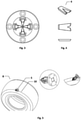
- Figure 1 shows a preferred embodiment in which the rotatable cutting head (5) has a plurality of cutting tools (1) and holes (6) to attach it to the robot arm by fasteners.
- Figure 2(b) represents a section (7) in which the cutting insert is located.
- the rotatable cutting head consists of at least two cutting tools.
- the cutting tools are located in the central part of the cutting head.
- Figure 3 Figure 1 shows a preferred embodiment of the rotatable cutting head having a plurality of cutting tools.
- FIG. 4 shows different views of the cutting insert (4), in which its V-shaped geometry can be seen.
- the Figure 5 shows a preferred embodiment of the cutting head (5) with the cutting tool on the tire surface (8) to cut the burr (10).
- Figure 6 Figure 1 shows a preferred embodiment showing a sectional view of the tire (8) and the contact surface (9) of the cutting head tool (5) with said tire, said cutting head tool (5) trimming the burr (10).
- the Figure 7 shows a preferred embodiment of the cutting tool (1) for trimming the shoulder ridge and the bead of a tire (8), in which the tool in the upper part of the figure cuts the ridge on the tire shoulder (8) and the tool in the cut the tire bead (8) in the lower part of the illustration.
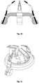
- FIGS 8, 9 and 10 show an optional embodiment of the cutting head, where said cutting tools are located on the side of the cutting head.
- FIGs 11, 12, 13 and 14 illustrate an optional embodiment of the cutting head, in which said cutting head consists of a plurality of cutting tools and cutting blades configured as shown in the figures.
- the cutting head consists of two cutting tools and two cutting blades, as in Figure 11 shown are configured.
Landscapes
- Engineering & Computer Science (AREA)
- Mechanical Engineering (AREA)
- Life Sciences & Earth Sciences (AREA)
- Forests & Forestry (AREA)
- Robotics (AREA)
- Tyre Moulding (AREA)
Applications Claiming Priority (1)
| Application Number | Priority Date | Filing Date | Title |
|---|---|---|---|
| PT11663220 | 2020-08-07 |
Publications (2)
| Publication Number | Publication Date |
|---|---|
| EP3954533A1 true EP3954533A1 (fr) | 2022-02-16 |
| EP3954533B1 EP3954533B1 (fr) | 2025-04-02 |
Family
ID=79554224
Family Applications (1)
| Application Number | Title | Priority Date | Filing Date |
|---|---|---|---|
| EP21187634.7A Active EP3954533B1 (fr) | 2020-08-07 | 2021-07-26 | Dispositif et procédé de coupe pour la bavure d'un pneu |
Country Status (1)
| Country | Link |
|---|---|
| EP (1) | EP3954533B1 (fr) |
Cited By (1)
| Publication number | Priority date | Publication date | Assignee | Title |
|---|---|---|---|---|
| EP4667204A1 (fr) * | 2024-06-17 | 2025-12-24 | Continental Reifen Deutschland GmbH | Dispositif d'ébavurage de pneu |
Citations (15)
| Publication number | Priority date | Publication date | Assignee | Title |
|---|---|---|---|---|
| US1148552A (en) * | 1914-09-24 | 1915-08-03 | Claude Tingle | Tire-casing-repair tool. |
| US1517395A (en) * | 1924-01-31 | 1924-12-02 | Chicago Pneumatic Tool Co | Cutting tool |
| GB384381A (en) * | 1931-09-19 | 1932-12-08 | Dunlop Rubber Co | Improvements in or relating to forming patterns on rubber goods including tyres |
| GB1128457A (en) * | 1964-12-19 | 1968-09-25 | Dunlop Co Ltd | Improvements in or relating to apparatus for cutting sheet material |
| US3618654A (en) * | 1969-08-28 | 1971-11-09 | Bandag Inc | High-speed cutting blade |
| GB1495209A (en) | 1974-07-06 | 1977-12-14 | Alpha Giken Kogyo Kk | Trimming apparatus for removing casting fins on a pneumatic tyre |
| CH598003A5 (fr) | 1975-06-27 | 1978-04-28 | Kaiser Wirz Max | |
| WO2007106961A1 (fr) * | 2006-03-17 | 2007-09-27 | Pirelli Pneus Ltda. | Dispositif et procede et retaillage de pneumatique |
| DE112009002549T5 (de) * | 2008-10-23 | 2012-09-20 | Fuji Seiko Co., Ltd. | Reifenvulkaniesierungsausbildungsform |
| CN104493841A (zh) * | 2014-12-31 | 2015-04-08 | 广东尚高科技有限公司 | 一种用于板材封边的修边装置 |
| CN105014848A (zh) | 2015-07-22 | 2015-11-04 | 双钱集团(江苏)轮胎有限公司 | 一种轮胎自动修边装置 |
| CN106671325A (zh) | 2017-01-16 | 2017-05-17 | 淮阴工学院 | 一种轮胎面修毛流水线 |
| CN107791422A (zh) * | 2017-11-22 | 2018-03-13 | 正新橡胶(中国)有限公司 | 一种修毛胶机构 |
| US10011054B1 (en) | 2016-12-14 | 2018-07-03 | Hyun Sang LEE | Cutter for trimming tread of tire |
| CN108515650A (zh) | 2017-10-25 | 2018-09-11 | 江苏大学 | 一种对tb轮胎侧面去毛刺装置 |
-
2021
- 2021-07-26 EP EP21187634.7A patent/EP3954533B1/fr active Active
Patent Citations (15)
| Publication number | Priority date | Publication date | Assignee | Title |
|---|---|---|---|---|
| US1148552A (en) * | 1914-09-24 | 1915-08-03 | Claude Tingle | Tire-casing-repair tool. |
| US1517395A (en) * | 1924-01-31 | 1924-12-02 | Chicago Pneumatic Tool Co | Cutting tool |
| GB384381A (en) * | 1931-09-19 | 1932-12-08 | Dunlop Rubber Co | Improvements in or relating to forming patterns on rubber goods including tyres |
| GB1128457A (en) * | 1964-12-19 | 1968-09-25 | Dunlop Co Ltd | Improvements in or relating to apparatus for cutting sheet material |
| US3618654A (en) * | 1969-08-28 | 1971-11-09 | Bandag Inc | High-speed cutting blade |
| GB1495209A (en) | 1974-07-06 | 1977-12-14 | Alpha Giken Kogyo Kk | Trimming apparatus for removing casting fins on a pneumatic tyre |
| CH598003A5 (fr) | 1975-06-27 | 1978-04-28 | Kaiser Wirz Max | |
| WO2007106961A1 (fr) * | 2006-03-17 | 2007-09-27 | Pirelli Pneus Ltda. | Dispositif et procede et retaillage de pneumatique |
| DE112009002549T5 (de) * | 2008-10-23 | 2012-09-20 | Fuji Seiko Co., Ltd. | Reifenvulkaniesierungsausbildungsform |
| CN104493841A (zh) * | 2014-12-31 | 2015-04-08 | 广东尚高科技有限公司 | 一种用于板材封边的修边装置 |
| CN105014848A (zh) | 2015-07-22 | 2015-11-04 | 双钱集团(江苏)轮胎有限公司 | 一种轮胎自动修边装置 |
| US10011054B1 (en) | 2016-12-14 | 2018-07-03 | Hyun Sang LEE | Cutter for trimming tread of tire |
| CN106671325A (zh) | 2017-01-16 | 2017-05-17 | 淮阴工学院 | 一种轮胎面修毛流水线 |
| CN108515650A (zh) | 2017-10-25 | 2018-09-11 | 江苏大学 | 一种对tb轮胎侧面去毛刺装置 |
| CN107791422A (zh) * | 2017-11-22 | 2018-03-13 | 正新橡胶(中国)有限公司 | 一种修毛胶机构 |
Non-Patent Citations (1)
| Title |
|---|
| TONSHOFF H K ET AL: "OFF-LINE-PROGRAMMIERSYSTEM ZUM REIFENSCHNEIDEN. ÖRAPID PROTOTYPING VON PKW-VERSUCHSREIFEN", WERKSTATTSTECHNIK, SPRINGER VERLAG. BERLIN, DE, vol. 86, no. 1/02, 1 January 1996 (1996-01-01), pages 19, XP000551789, ISSN: 0340-4544 * |
Cited By (1)
| Publication number | Priority date | Publication date | Assignee | Title |
|---|---|---|---|---|
| EP4667204A1 (fr) * | 2024-06-17 | 2025-12-24 | Continental Reifen Deutschland GmbH | Dispositif d'ébavurage de pneu |
Also Published As
| Publication number | Publication date |
|---|---|
| EP3954533B1 (fr) | 2025-04-02 |
Similar Documents
| Publication | Publication Date | Title |
|---|---|---|
| DE102010018284B4 (de) | Turbinenschaufelrohling sowie Verfahren und Vorrichtung zum Bearbeiten eines Turbinenschaufelrohlings | |
| DE3039222C2 (fr) | ||
| DE102011110779B4 (de) | Verfahren zur Fräsbearbeitung eines Rohlings bei der Herstellung einer Turbinenschaufel | |
| DE2820220C3 (de) | Auswechselbare Klinge für die drehbare Nabe einer Maschine zum Abtragen von Reifenlaufflächen | |
| DE69009850T2 (de) | Raspelblatt für Fahrzeugreifen. | |
| DE19739976C2 (de) | Verfahren und Vorrichtung zum Zerschneiden eines Drahtes in kurze Stücke während dessen Zuführung | |
| DE3025074C2 (de) | Vorrichtung zum spanabhebenden Entgraten bzw. Anfasen eines bandförmigen Werkstücks | |
| EP3954533A1 (fr) | Dispositif et procédé de coupe pour la bavure d'un pneu | |
| DE2714468C2 (de) | Metallstreifen mit voneinander beabstandeten Klingen zur Herstellung chirurgischer Klingen und Verfahren zur Aufbereitung | |
| DE69015189T2 (de) | Gebüschschneideblatt. | |
| DE102018114138A1 (de) | Tieflochbohrer mit mehreren Spanformern und Mulden in der Spanfläche | |
| DE19928840C1 (de) | Schaftwerkzeug mit fest angeordneten flügelartigen Einsätzen | |
| DE1752595B2 (de) | Verfahren zur herstellung von schaufelradschaufeln fuer axialstroemungsmaschinen | |
| DE202013004984U1 (de) | Werkzeug zum spanenden Bearbeiten eines Werkstücks | |
| DE2529581A1 (de) | Abgrateinrichtung | |
| EP0145049B1 (fr) | Dispositif à dénuder, en particulier pour des conducteurs isolés par une matière tenace | |
| DE69228809T2 (de) | Maschine zum schaerfen von saegeblaettern | |
| DE102004040580B4 (de) | Fräser | |
| EP4015121B1 (fr) | Outil de chanfreinage à commande par pression à centrage des lames | |
| DE10136534B4 (de) | Wafer-Schneidemaschine | |
| DE2429145B2 (de) | Vorrichtung zum abheben der gummischicht eines fahrzeugreifens | |
| EP2582480B1 (fr) | Utilisation d'un dispositif de tournage | |
| CH648495A5 (de) | Pelletizer. | |
| DE3241948C2 (fr) | ||
| DE2700062A1 (de) | Schlauch-zusammenfuegmaschine |
Legal Events
| Date | Code | Title | Description |
|---|---|---|---|
| PUAI | Public reference made under article 153(3) epc to a published international application that has entered the european phase |
Free format text: ORIGINAL CODE: 0009012 |
|
| STAA | Information on the status of an ep patent application or granted ep patent |
Free format text: STATUS: THE APPLICATION HAS BEEN PUBLISHED |
|
| AK | Designated contracting states |
Kind code of ref document: A1 Designated state(s): AL AT BE BG CH CY CZ DE DK EE ES FI FR GB GR HR HU IE IS IT LI LT LU LV MC MK MT NL NO PL PT RO RS SE SI SK SM TR |
|
| STAA | Information on the status of an ep patent application or granted ep patent |
Free format text: STATUS: REQUEST FOR EXAMINATION WAS MADE |
|
| 17P | Request for examination filed |
Effective date: 20220816 |
|
| RBV | Designated contracting states (corrected) |
Designated state(s): AL AT BE BG CH CY CZ DE DK EE ES FI FR GB GR HR HU IE IS IT LI LT LU LV MC MK MT NL NO PL PT RO RS SE SI SK SM TR |
|
| STAA | Information on the status of an ep patent application or granted ep patent |
Free format text: STATUS: EXAMINATION IS IN PROGRESS |
|
| 17Q | First examination report despatched |
Effective date: 20231220 |
|
| RAP3 | Party data changed (applicant data changed or rights of an application transferred) |
Owner name: CONTINENTAL REIFEN DEUTSCHLAND GMBH |
|
| GRAP | Despatch of communication of intention to grant a patent |
Free format text: ORIGINAL CODE: EPIDOSNIGR1 |
|
| STAA | Information on the status of an ep patent application or granted ep patent |
Free format text: STATUS: GRANT OF PATENT IS INTENDED |
|
| INTG | Intention to grant announced |
Effective date: 20241216 |
|
| RIC1 | Information provided on ipc code assigned before grant |
Ipc: B25J 11/00 20060101ALI20241206BHEP Ipc: B26D 7/26 20060101ALI20241206BHEP Ipc: B26D 3/28 20060101ALI20241206BHEP Ipc: B26D 1/00 20060101ALI20241206BHEP Ipc: B29D 30/06 20060101AFI20241206BHEP |
|
| GRAS | Grant fee paid |
Free format text: ORIGINAL CODE: EPIDOSNIGR3 |
|
| GRAA | (expected) grant |
Free format text: ORIGINAL CODE: 0009210 |
|
| STAA | Information on the status of an ep patent application or granted ep patent |
Free format text: STATUS: THE PATENT HAS BEEN GRANTED |
|
| P01 | Opt-out of the competence of the unified patent court (upc) registered |
Free format text: CASE NUMBER: APP_5518/2025 Effective date: 20250203 |
|
| AK | Designated contracting states |
Kind code of ref document: B1 Designated state(s): AL AT BE BG CH CY CZ DE DK EE ES FI FR GB GR HR HU IE IS IT LI LT LU LV MC MK MT NL NO PL PT RO RS SE SI SK SM TR |
|
| REG | Reference to a national code |
Ref country code: GB Ref legal event code: FG4D Free format text: NOT ENGLISH |
|
| REG | Reference to a national code |
Ref country code: CH Ref legal event code: EP |
|
| REG | Reference to a national code |
Ref country code: IE Ref legal event code: FG4D Free format text: LANGUAGE OF EP DOCUMENT: GERMAN |
|
| REG | Reference to a national code |
Ref country code: DE Ref legal event code: R096 Ref document number: 502021007078 Country of ref document: DE |
|
| REG | Reference to a national code |
Ref country code: PT Ref legal event code: SC4A Ref document number: 3954533 Country of ref document: PT Date of ref document: 20250505 Kind code of ref document: T Free format text: AVAILABILITY OF NATIONAL TRANSLATION Effective date: 20250429 |
|
| REG | Reference to a national code |
Ref country code: NL Ref legal event code: MP Effective date: 20250402 |
|
| PG25 | Lapsed in a contracting state [announced via postgrant information from national office to epo] |
Ref country code: NL Free format text: LAPSE BECAUSE OF FAILURE TO SUBMIT A TRANSLATION OF THE DESCRIPTION OR TO PAY THE FEE WITHIN THE PRESCRIBED TIME-LIMIT Effective date: 20250402 |
|
| PG25 | Lapsed in a contracting state [announced via postgrant information from national office to epo] |
Ref country code: FI Free format text: LAPSE BECAUSE OF FAILURE TO SUBMIT A TRANSLATION OF THE DESCRIPTION OR TO PAY THE FEE WITHIN THE PRESCRIBED TIME-LIMIT Effective date: 20250402 Ref country code: ES Free format text: LAPSE BECAUSE OF FAILURE TO SUBMIT A TRANSLATION OF THE DESCRIPTION OR TO PAY THE FEE WITHIN THE PRESCRIBED TIME-LIMIT Effective date: 20250402 |
|
| PGFP | Annual fee paid to national office [announced via postgrant information from national office to epo] |
Ref country code: PT Payment date: 20250717 Year of fee payment: 5 |
|
| PGFP | Annual fee paid to national office [announced via postgrant information from national office to epo] |
Ref country code: DE Payment date: 20250731 Year of fee payment: 5 |
|
| REG | Reference to a national code |
Ref country code: LT Ref legal event code: MG9D |
|
| PG25 | Lapsed in a contracting state [announced via postgrant information from national office to epo] |
Ref country code: NO Free format text: LAPSE BECAUSE OF FAILURE TO SUBMIT A TRANSLATION OF THE DESCRIPTION OR TO PAY THE FEE WITHIN THE PRESCRIBED TIME-LIMIT Effective date: 20250702 Ref country code: GR Free format text: LAPSE BECAUSE OF FAILURE TO SUBMIT A TRANSLATION OF THE DESCRIPTION OR TO PAY THE FEE WITHIN THE PRESCRIBED TIME-LIMIT Effective date: 20250703 |
|
| PG25 | Lapsed in a contracting state [announced via postgrant information from national office to epo] |
Ref country code: PL Free format text: LAPSE BECAUSE OF FAILURE TO SUBMIT A TRANSLATION OF THE DESCRIPTION OR TO PAY THE FEE WITHIN THE PRESCRIBED TIME-LIMIT Effective date: 20250402 |
|
| PG25 | Lapsed in a contracting state [announced via postgrant information from national office to epo] |
Ref country code: BG Free format text: LAPSE BECAUSE OF FAILURE TO SUBMIT A TRANSLATION OF THE DESCRIPTION OR TO PAY THE FEE WITHIN THE PRESCRIBED TIME-LIMIT Effective date: 20250402 |
|
| PG25 | Lapsed in a contracting state [announced via postgrant information from national office to epo] |
Ref country code: HR Free format text: LAPSE BECAUSE OF FAILURE TO SUBMIT A TRANSLATION OF THE DESCRIPTION OR TO PAY THE FEE WITHIN THE PRESCRIBED TIME-LIMIT Effective date: 20250402 |
|
| PGFP | Annual fee paid to national office [announced via postgrant information from national office to epo] |
Ref country code: FR Payment date: 20250725 Year of fee payment: 5 Ref country code: AT Payment date: 20251020 Year of fee payment: 5 |
|
| PG25 | Lapsed in a contracting state [announced via postgrant information from national office to epo] |
Ref country code: RS Free format text: LAPSE BECAUSE OF FAILURE TO SUBMIT A TRANSLATION OF THE DESCRIPTION OR TO PAY THE FEE WITHIN THE PRESCRIBED TIME-LIMIT Effective date: 20250702 |
|
| PG25 | Lapsed in a contracting state [announced via postgrant information from national office to epo] |
Ref country code: IS Free format text: LAPSE BECAUSE OF FAILURE TO SUBMIT A TRANSLATION OF THE DESCRIPTION OR TO PAY THE FEE WITHIN THE PRESCRIBED TIME-LIMIT Effective date: 20250802 |
|
| PG25 | Lapsed in a contracting state [announced via postgrant information from national office to epo] |
Ref country code: LV Free format text: LAPSE BECAUSE OF FAILURE TO SUBMIT A TRANSLATION OF THE DESCRIPTION OR TO PAY THE FEE WITHIN THE PRESCRIBED TIME-LIMIT Effective date: 20250402 |
|
| REG | Reference to a national code |
Ref country code: DE Ref legal event code: R097 Ref document number: 502021007078 Country of ref document: DE |
|
| PG25 | Lapsed in a contracting state [announced via postgrant information from national office to epo] |
Ref country code: SM Free format text: LAPSE BECAUSE OF FAILURE TO SUBMIT A TRANSLATION OF THE DESCRIPTION OR TO PAY THE FEE WITHIN THE PRESCRIBED TIME-LIMIT Effective date: 20250402 Ref country code: DK Free format text: LAPSE BECAUSE OF FAILURE TO SUBMIT A TRANSLATION OF THE DESCRIPTION OR TO PAY THE FEE WITHIN THE PRESCRIBED TIME-LIMIT Effective date: 20250402 |
|
| PG25 | Lapsed in a contracting state [announced via postgrant information from national office to epo] |
Ref country code: CZ Free format text: LAPSE BECAUSE OF FAILURE TO SUBMIT A TRANSLATION OF THE DESCRIPTION OR TO PAY THE FEE WITHIN THE PRESCRIBED TIME-LIMIT Effective date: 20250402 |
|
| PG25 | Lapsed in a contracting state [announced via postgrant information from national office to epo] |
Ref country code: EE Free format text: LAPSE BECAUSE OF FAILURE TO SUBMIT A TRANSLATION OF THE DESCRIPTION OR TO PAY THE FEE WITHIN THE PRESCRIBED TIME-LIMIT Effective date: 20250402 |
|
| PG25 | Lapsed in a contracting state [announced via postgrant information from national office to epo] |
Ref country code: RO Free format text: LAPSE BECAUSE OF FAILURE TO SUBMIT A TRANSLATION OF THE DESCRIPTION OR TO PAY THE FEE WITHIN THE PRESCRIBED TIME-LIMIT Effective date: 20250402 Ref country code: SK Free format text: LAPSE BECAUSE OF FAILURE TO SUBMIT A TRANSLATION OF THE DESCRIPTION OR TO PAY THE FEE WITHIN THE PRESCRIBED TIME-LIMIT Effective date: 20250402 |
|
| PG25 | Lapsed in a contracting state [announced via postgrant information from national office to epo] |
Ref country code: IT Free format text: LAPSE BECAUSE OF FAILURE TO SUBMIT A TRANSLATION OF THE DESCRIPTION OR TO PAY THE FEE WITHIN THE PRESCRIBED TIME-LIMIT Effective date: 20250402 |
|
| PLBE | No opposition filed within time limit |
Free format text: ORIGINAL CODE: 0009261 |
|
| STAA | Information on the status of an ep patent application or granted ep patent |
Free format text: STATUS: NO OPPOSITION FILED WITHIN TIME LIMIT |
|
| REG | Reference to a national code |
Ref country code: CH Ref legal event code: L10 Free format text: ST27 STATUS EVENT CODE: U-0-0-L10-L00 (AS PROVIDED BY THE NATIONAL OFFICE) Effective date: 20260211 |
|
| REG | Reference to a national code |
Ref country code: CH Ref legal event code: H13 Free format text: ST27 STATUS EVENT CODE: U-0-0-H10-H13 (AS PROVIDED BY THE NATIONAL OFFICE) Effective date: 20260224 |
|
| 26N | No opposition filed |
Effective date: 20260105 |
|
| PG25 | Lapsed in a contracting state [announced via postgrant information from national office to epo] |
Ref country code: LU Free format text: LAPSE BECAUSE OF NON-PAYMENT OF DUE FEES Effective date: 20250726 |
|
| GBPC | Gb: european patent ceased through non-payment of renewal fee |
Effective date: 20250726 |
|
| REG | Reference to a national code |
Ref country code: BE Ref legal event code: MM Effective date: 20250731 |
|
| PG25 | Lapsed in a contracting state [announced via postgrant information from national office to epo] |
Ref country code: GB Free format text: LAPSE BECAUSE OF NON-PAYMENT OF DUE FEES Effective date: 20250726 |
|
| PG25 | Lapsed in a contracting state [announced via postgrant information from national office to epo] |
Ref country code: BE Free format text: LAPSE BECAUSE OF NON-PAYMENT OF DUE FEES Effective date: 20250731 |
|
| PG25 | Lapsed in a contracting state [announced via postgrant information from national office to epo] |
Ref country code: CH Free format text: LAPSE BECAUSE OF NON-PAYMENT OF DUE FEES Effective date: 20250731 |