EP3954848A2 - Verriegelung für handschuhfach eines fahrzeugs - Google Patents
Verriegelung für handschuhfach eines fahrzeugs Download PDFInfo
- Publication number
- EP3954848A2 EP3954848A2 EP21189197.3A EP21189197A EP3954848A2 EP 3954848 A2 EP3954848 A2 EP 3954848A2 EP 21189197 A EP21189197 A EP 21189197A EP 3954848 A2 EP3954848 A2 EP 3954848A2
- Authority
- EP
- European Patent Office
- Prior art keywords
- rotor
- housing
- paddle
- latch assembly
- door
- Prior art date
- Legal status (The legal status is an assumption and is not a legal conclusion. Google has not performed a legal analysis and makes no representation as to the accuracy of the status listed.)
- Pending
Links
Images

















Classifications
-
- E—FIXED CONSTRUCTIONS
- E05—LOCKS; KEYS; WINDOW OR DOOR FITTINGS; SAFES
- E05B—LOCKS; ACCESSORIES THEREFOR; HANDCUFFS
- E05B83/00—Vehicle locks specially adapted for particular types of wing or vehicle
- E05B83/28—Locks for glove compartments, console boxes, fuel inlet covers or the like
- E05B83/30—Locks for glove compartments, console boxes, fuel inlet covers or the like for glove compartments
-
- E—FIXED CONSTRUCTIONS
- E05—LOCKS; KEYS; WINDOW OR DOOR FITTINGS; SAFES
- E05B—LOCKS; ACCESSORIES THEREFOR; HANDCUFFS
- E05B13/00—Devices preventing the key or the handle or both from being used
- E05B13/10—Devices preventing the key or the handle or both from being used formed by a lock arranged in the handle
-
- E—FIXED CONSTRUCTIONS
- E05—LOCKS; KEYS; WINDOW OR DOOR FITTINGS; SAFES
- E05B—LOCKS; ACCESSORIES THEREFOR; HANDCUFFS
- E05B47/00—Operating or controlling locks or other fastening devices by electric or magnetic means
- E05B47/0001—Operating or controlling locks or other fastening devices by electric or magnetic means with electric actuators; Constructional features thereof
- E05B47/0012—Operating or controlling locks or other fastening devices by electric or magnetic means with electric actuators; Constructional features thereof with rotary electromotors
-
- E—FIXED CONSTRUCTIONS
- E05—LOCKS; KEYS; WINDOW OR DOOR FITTINGS; SAFES
- E05B—LOCKS; ACCESSORIES THEREFOR; HANDCUFFS
- E05B5/00—Handles completely let into the surface of the wing
-
- E—FIXED CONSTRUCTIONS
- E05—LOCKS; KEYS; WINDOW OR DOOR FITTINGS; SAFES
- E05B—LOCKS; ACCESSORIES THEREFOR; HANDCUFFS
- E05B79/00—Mounting or connecting vehicle locks or parts thereof
- E05B79/02—Mounting of vehicle locks or parts thereof
- E05B79/08—Mounting of individual lock elements in the lock, e.g. levers
-
- E—FIXED CONSTRUCTIONS
- E05—LOCKS; KEYS; WINDOW OR DOOR FITTINGS; SAFES
- E05B—LOCKS; ACCESSORIES THEREFOR; HANDCUFFS
- E05B81/00—Power-actuated vehicle locks
- E05B81/02—Power-actuated vehicle locks characterised by the type of actuators used
- E05B81/04—Electrical
- E05B81/06—Electrical using rotary motors
-
- E—FIXED CONSTRUCTIONS
- E05—LOCKS; KEYS; WINDOW OR DOOR FITTINGS; SAFES
- E05B—LOCKS; ACCESSORIES THEREFOR; HANDCUFFS
- E05B85/00—Details of vehicle locks not provided for in groups E05B77/00 - E05B83/00
-
- E—FIXED CONSTRUCTIONS
- E05—LOCKS; KEYS; WINDOW OR DOOR FITTINGS; SAFES
- E05C—BOLTS OR FASTENING DEVICES FOR WINGS, SPECIALLY FOR DOORS OR WINDOWS
- E05C9/00—Arrangements of simultaneously actuated bolts or other securing devices at well-separated positions on the same wing
-
- E—FIXED CONSTRUCTIONS
- E05—LOCKS; KEYS; WINDOW OR DOOR FITTINGS; SAFES
- E05C—BOLTS OR FASTENING DEVICES FOR WINGS, SPECIALLY FOR DOORS OR WINDOWS
- E05C9/00—Arrangements of simultaneously actuated bolts or other securing devices at well-separated positions on the same wing
- E05C9/006—Details of bars
-
- E—FIXED CONSTRUCTIONS
- E05—LOCKS; KEYS; WINDOW OR DOOR FITTINGS; SAFES
- E05C—BOLTS OR FASTENING DEVICES FOR WINGS, SPECIALLY FOR DOORS OR WINDOWS
- E05C9/00—Arrangements of simultaneously actuated bolts or other securing devices at well-separated positions on the same wing
- E05C9/04—Arrangements of simultaneously actuated bolts or other securing devices at well-separated positions on the same wing with two sliding bars moved in opposite directions when fastening or unfastening
- E05C9/043—Arrangements of simultaneously actuated bolts or other securing devices at well-separated positions on the same wing with two sliding bars moved in opposite directions when fastening or unfastening with crank pins and connecting rods
-
- E—FIXED CONSTRUCTIONS
- E05—LOCKS; KEYS; WINDOW OR DOOR FITTINGS; SAFES
- E05B—LOCKS; ACCESSORIES THEREFOR; HANDCUFFS
- E05B15/00—Other details of locks; Parts for engagement by bolts of fastening devices
- E05B15/04—Spring arrangements in locks
- E05B2015/0403—Wound springs
- E05B2015/0406—Wound springs wound in a cylindrical shape
-
- E—FIXED CONSTRUCTIONS
- E05—LOCKS; KEYS; WINDOW OR DOOR FITTINGS; SAFES
- E05B—LOCKS; ACCESSORIES THEREFOR; HANDCUFFS
- E05B15/00—Other details of locks; Parts for engagement by bolts of fastening devices
- E05B15/04—Spring arrangements in locks
- E05B2015/0437—Attachments or mountings; Mounting of springs
Definitions
- the present invention relates to the field of latches or connector systems configured to provide a mechanical connection between adjacent components, and particularly to latch systems for securing automotive glove box or accessory compartment doors in the closed position.
- Automotive door closure systems such as glove boxes and the like, typically include a housing, a door, and a latch that cooperates with one or more strikers to hold the door in the closed position to cover the housing. It has been found that there is a continuing need to improve upon or provide alternatives to existing door closure systems.
- a vehicle glove box latch for a vehicle glove box.
- the vehicle glove box latch comprises a housing that is configured to be connected to a vehicle glove box, a user operated paddle that is pivotably connected to a paddle mounting portion of the housing, a rotor that is pivotably connected to a rotor mounting portion of the housing, at least one pawl coupled to the rotor and having an end that is configured to be engaged with an opening in the vehicle to which the vehicle glove box is mounted, and a lock barrel mounted to the housing for locking and unlocking the vehicle glove box latch. In a locked state of the lock barrel, the at least one pawl cannot be disengaged from the opening in the vehicle.
- the at least one pawl can be disengaged from the opening in the vehicle for opening the vehicle glove box.
- the lock barrel, the rotor and the rotor mounting portion are concentrically aligned along an axis, which reduces the depth of the latch, which reduces the space in the glove box necessary for accommodating the latch, thereby resulting in an increase in the available storage space in the glove box.
- a method for assembling the vehicle glove box latch assembly comprises the steps of:
- the vehicle glove box latch comprises a housing having a front surface facing away from the vehicle glove box, a rear surface opposite the front surface, and at least one side surface interconnecting the front surface and the rear surface.
- a retention feature on the housing extends in a lateral direction beyond the at least one side surface of the housing for mounting to an opening formed in the vehicle glove box.
- Means for mounting the rear side of the housing to the vehicle glove box is/are provided.
- a user operated paddle is pivotably connected to a paddle mounting portion of the housing such that at least a portion of the paddle is positioned in front of the front surface of the housing. The paddle is configured to move from a home position to a deployed position for opening the vehicle glove box.
- the vehicle glove box latch comprises a housing that is configured to be connected to a vehicle glove box, a user operated paddle that is pivotably connected to a paddle mounting portion of the housing, a rotor that is pivotably connected to a rotor mounting portion of the housing, and at least one pawl coupled to the rotor and having opposing ends.
- One end of the opposing ends of the pawl includes an engagement portion that is configured to be engaged with an opening in the vehicle in which the glove box is mounted, and the other end of the opposing ends of the pawl includes a post that is mounted in an opening in the rotor for securing the pawl to the rotor.
- a vehicle glove box comprises a door, a latch assembly housing, and a user operated paddle.
- the door is configured to pivot between open and closed positions relative to a vehicle dashboard and has an opening and a hole.
- the latch assembly housing has a front surface facing away from the door, a rear surface opposite the front surface, at least one side surface interconnecting the front surface and the rear surface, and a retention feature on the housing that extends in a lateral direction beyond the at least one side surface of the housing for mounting to the opening formed in the door.
- a fastener is configured to be mounted through the hole of the door and onto the rear surface of the latch assembly housing for mounting the door to the latch assembly housing.
- a user operated paddle is pivotably connected to a paddle mounting portion of the latch assembly housing such that the paddle is positioned in front of the front surface of the latch assembly housing. The paddle is configured to move from a home position to a deployed position for opening the vehicle glove box.
- a vehicle glove box latch comprises a housing that is configured to be connected to the vehicle glove box, a user operated paddle that is pivotably connected to a paddle mounting portion of the housing, a deadbolt that is movable with respect to the paddle between a locked position and an unlocked position, and an actuator that is engaged with the deadbolt and configured to move the deadbolt between the locked position and the unlocked position.
- the deadbolt In the locked position of the deadbolt, the deadbolt is positioned to prevent the paddle from moving from the home position toward the deployed position, and, in the unlocked position of the deadbolt, the deadbolt is positioned to permit the paddle to move from the home position toward the deployed position.
- a method for assembling a latch assembly comprises positioning a coiled body of a spring on a rotor; mounting a first leg of the spring into a first spring mounting recess formed on the rotor; moving a second leg of the spring with respect to the rotor and positioning the second leg into a second spring mounting recess formed on the rotor; mounting the rotor onto a rotor receiving portion of a housing of the latch assembly; and pivoting the rotor relative to the housing to connect the rotor to the housing.
- a vehicle glove box latch for a vehicle glove box comprises a housing that is configured to be connected to the vehicle glove box; a user operated paddle that is pivotably connected to a paddle mounting portion of the housing, the paddle configured for movement between a home position and a deployed position; a rotor that is pivotably connected to a rotor mounting portion of the housing, the rotor including a set of pawl receiving portions; and two pawls each having opposing ends, wherein one end of the opposing ends of each pawl includes an engagement portion that is configured to be engaged either directly or indirectly with an opening in the vehicle in which the glove box is mounted, and the other end of the opposing ends of each pawl is coupled to one of the pawl receiving portions.
- the vehicle glove box latch In one orientation of the pawls, the vehicle glove box latch is configured to be operated in a vertical-lift configuration, and in another orientation of the pawls, the vehicle glove box latch is configured to be operated in a side-pull configuration.
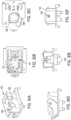
- FIGs. 1A through 14B A first embodiment of a door assembly 100 incorporating aspects of the present invention is illustrated in FIGs. 1A through 14B .
- the door assembly 100 generally includes a door 102 (only the front panel of which is shown).
- the door 102 may be a glove box door for a vehicle, for example.
- the door is mounted over an opening, such as an opening formed in the dashboard of a vehicle.
- the door 12 is hinged to the opening and can move between a closed position and an open position, as is known in the art.
- the door 102 may be a unitary component or composed of multiple components mounted together.
- the door 102 includes a generally rectangular shape having a substantially rectangular recessed region 106 on its front face 107. Two projections 115 and 119 project outward in a rear facing direction from the rear face of the door 102.
- the projection 115 includes an aperture extending therethrough.
- a hollow square-shaped clip 121 is mounted to the aperture in the projection 115.
- Each interior facing side of the clip 121 include resilient tabs 129 that are capable of accommodating transverse motion of the pawl that is positioned therein.
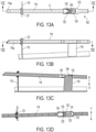
- the projection 119 has a free end 131 that is narrower than the remainder of the projection 119, as best shown in FIG. 13D .
- An elongated recess 133 or channel is formed at the rear facing surface of the free end 131. The purpose of the projections 115 and 119 will be described in greater detail with reference to FIGs. 13A-13D .
- a latch assembly 104 is mounted to the door 102 to releasably retain the door 102 in the closed position.
- the latch assembly 104 is at least partially positioned within the recessed region 106 of the door 102 such that the front face of the paddle 400 of the latch assembly is either flush with or slightly recessed with respect to the front face 107 of the door 102. Alternatively, the paddle 400 may slightly protrude or significantly protrude, as dictated by the design.
- the latch assembly 104 is mounted to the recessed region 106 of the door 102 by a threaded fastener 109 and a clip 307 on a housing 300 of the latch assembly 104, as will be described later with reference to the method of assembling the door assembly 100.
- the fastener 109 together with the clip 307 comprise a means for mounting the latch assembly 104 to the door 102.
- the means for mounting can vary.
- the means for mounting may comprise a plurality of clips, a plurality of fasteners, a snap, a clamp, a weld, an adhesive, a barb, a slot, a prong, or a surface, for example, or any other device that can be used to mount the latch assembly 104 to the door 102.
- the latch assembly 104 protrudes from the rear face 110 of the door 102 and through an opening 113 formed in the recessed region 106.
- the pawls 112 and 114 are configured to releasably engage the strikers on the vehicle opening.
- the pawls 112 and 114 are engaged with the strikers, the door 102 is maintained in the closed position.
- Engagement between the free ends 112a and 114a of the pawls 112 and 114, respectively and their respective strikers prevents the door 102 from being moved to the open position from the closed position.
- the pawls 112 and 114 are separated from the strikers, the door 102 is either maintained in the open position or can readily be moved to the open position.
- each pawl 112 and 114 Opposite the free end 112a and 114a of each pawl 112 and 114 is a post 120 and 127, respectively, that is connected to the rotor 500 of the latch assembly 104.
- the post 120 of the pawl 112 includes a shaft 128a that extends from the end of the pawl 112, a bulbous portion 128b at the free end of the shaft 128a, and an annular channel 128c defined between the shaft 128a and the bulbous portion 128b.
- the post 127 of the pawl 114 is substantially identical to the post 120.
- the connection between the pawls 112 and 114 and the rotor 500 may be any type of connection (fixed or releasable), and is not limited to the connection that is shown.
- the pawl 114 is both positioned through the clip 121 on the door 102, and mounted above the projection 119 on the door 102.
- the pawl 114 includes a guide segment 123 that interacts with the projection 119.
- the guide segment 123 includes an opening 124 formed at a widened region of the pawl 114.
- Two prongs 125 extend into the opening 124 and toward one another from opposing sides of the opening 124. The prongs 125 approach but do not cross the central axis 'E' ( FIG. 13A ) of the pawl 114.
- Each prong 125 is v-shaped and the point of the v-shape points toward the central axis E.
- a prong 126 is formed on a side of the opening 124 that is adjacent to both sides of the opening 124 to which the prongs 125 are mounted.
- the prong 126 extends along the axis E. Also, as shown in FIG. 13A , the prong 126 extends to a length along the central axis E such that it passes over the prongs 125.
- the prong 126 is positioned at an elevation above the prongs 125 such that the prongs 125 and 126 do not contact each other, as shown in FIG. 13C .
- the prongs 125 and 126 may be integral with the pawl 114 or provided on a separate component that is mounted in the opening 124.
- the prongs 125 and 126 are flexible.
- the prongs 125 interact with the sides of the free end 131 of the projection 119, as shown in FIG. 13D , whereas the prong 126 interacts with the recess 133 formed in the free end 131. Interaction between the pawl 114 and the projection 119 will be described in greater detail with reference to FIGs. 13A-13D .
- FIG. 2 depicts an exploded view of the latch assembly 104.
- the primary components of the latch assembly 104 are a base housing 300, a user-operated paddle 400, a rotor 500, a lock barrel 600, torsion springs 700 and 800, and, optionally, two pawls 112 and 114.
- the base housing 300 is mountable to the front side of the door 102 and remains fixed in place (i.e., stationary) during operation of the latch assembly 104.
- the paddle 400 is pivotably mounted with respect to the front face 302 of the housing 300 about a pivot axis A (see FIG. 12C ).
- the rotor 500 is rotatably mounted to the rear face 304 of the housing 300 about concentric axis B (see FIGs.
- the pawls 112 and 114 which may or may not be considered as forming part of the latch assembly 104, are mounted to the rotor 500.
- the lock barrel 600 is mounted to the housing 300 and aligned with an opening 402 in the paddle 400.
- the lock barrel 600 is provided for either locking or unlocking the latch assembly 104.
- the lock barrel 600 is an optional component and may be omitted.
- the torsion spring 700 is connected to the paddle 400 for retaining the paddle 400 in the home position shown in FIG. 1A .
- the second torsion spring 800 is connected to the rotor 500 for biasing the rotor 500 to a rotational position corresponding to the closed state of the latch assembly 104 (i.e., in which the pawls 112 and 114 are engaged with the strikers).
- FIGs. 3A-3G depict the base housing 300 of the latch assembly 104.
- the base housing 300 has a substantially rectangular body to which the other components of the latch assembly 104 are mounted.
- a recess 301 extends through the housing 300 (unless the latch assembly 104 does not include the lock barrel 600).
- the outer barrel of the lock barrel 600 is fixed within the recess 301.
- the base housing 300 includes the clip 307 for mounting the door 102.
- the clip 307 is formed on one side of the housing 300.
- the clip 307 is a flexible tab or prong that extends outwardly from the side of the housing 300.
- the clip 307 may also be referred to herein as a retention feature, and the retention feature may be a post, surface, clamp, slot, or projection, for example.
- Two arcuate shaped ribs 310 protrude from the side walls 311 of the housing 300.
- the ribs 310 are configured to be positioned within corresponding arcuate shaped slots 404 disposed on the side walls 311 of the paddle 400.
- the slots 404 are longer (as measured by either length or arc length) than the ribs 310 such that the paddle 400 is capable of pivoting with respect to the housing 300 (compare FIGs. 12A and 12B ).
- the paddle 400 can pivot with respect to the housing 300 about axis A due to the engagement between the slots 404 and the ribs 310.
- the ribs 310 may be referred to more generally as a paddle mounting portion of the housing 300. It should be understood that the connection between the housing 300 and the paddle 400 may vary from that which is shown and described. For example, the paddle 400 may be connected to the housing 300 by a post, clip, shaft, fastener, pin, or hinge, for example.
- a hollow cylinder 312 protrudes rearwardly from the rear face 304 of the housing 300.
- the cylinder 312 is collinear with the recess 301, and the interior of the cylinder 312 defines at least a portion of the recess 301.
- the cylinder 312 is interrupted by two flexible prongs 314 that are positioned on opposite sides of the cylinder 312.
- Each prong 314 includes a barb 316 at its end, and each prong 314 is configured to flex with respect to the cylinder 312.
- the barbs 316 are configured to connect to slots 506 formed in the rotor 500. Engagement between the barbs 316 and their respective slots 506 retains the rotor 500 to the housing 300.
- the slots 506 are longer (as measured by either length or arc length) than the barbs 316 such that the rotor 500 is capable of rotating with respect to the housing 300 without detaching from the housing 300 (compare FIGs. 9C, 10C and 11C ).
- the engagement between the housing 300 and the rotor 500 can vary.
- the prongs 314 may be fixed (instead of flexible) and keyed with a slot formed in the rotor 500.
- the interface between the cylinder 312 and the hollow space 530 formed by the cylindrical inner wall 501 may be switched such that the inner diameter of the cylinder 312 is the interface with the rotor 500 as opposed to the outer diameter of the cylinder 312, as shown.
- the cylinder 312 and the prongs 314 may be referred to more generally as a rotor mounting portion of the housing 300. It should be understood that the connection between the housing 300 and the rotor 500 may vary from that which is shown and described. For example, the rotor 500 may be connected to the housing 300 by a post, clamp, barb, surface, fastener, clip, or shaft, for example.
- the rotor mounting portion of the housing 300, the rotor 500 and the lock barrel 600 at least partially overlap one another along the axis 'B' and are concentrically aligned along the same axis 'B.'
- This arrangement results in decreased depth 'D' (see FIG. 9B ) of the latch assembly 104, which results in decreased depth of the recess 106 in the glove box door 102 needed to accommodate the latch assembly 104, which results in increased available storage space in the glove box.
- Two alignment pins 318 protrude from the rear face 304 of the housing 300. Each pin 318 is configured to be inserted into a hole 130 ( FIG. 1B ) disposed in the door 102 for alignment purposes.
- Two tracks 320 are formed on opposite side walls 311 of the housing 300.
- Posts 407 on the paddle 400 travel in respective tracks 320 upon pivoting the paddle 400.
- the posts 407 interact with the tracks 320 to limit pivoting action of the paddle 400 beyond a predetermined point, and aid in preventing the paddle 400 from becoming detached from the housing 300.
- Each track 320 is an indentation formed in the side wall 311.
- the track 320 protrudes into and is at least partially formed on a shoulder 317 that is formed on the underside of the rear face 304 of the housing 300.
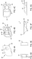
- FIGs. 4A-4G depict the paddle 400 of the latch assembly 104.
- the paddle 400 includes a substantially rectangular front face 410 in the form of a wall.
- the opening 402 for accommodating the lock barrel 600 is defined in the face 410.
- the opening 402 may be omitted if the lock barrel 600 is omitted.
- the end 412 of the front face 410 furthest from the slots 404 is configured to be grasped by a user of the latch assembly 104.
- Opposing side walls 414 and 416 protrude downwardly from the front face 410.
- the side wall 414 includes one of the two slots 404, and a rounded leg 420 extending downwardly from the wall 414 at a location adjacent the slot 404.
- the rounded leg 420 is configured for rotating the rotor 500, as will be described later.
- One of the two posts 407 extends inwardly from the bottom edge of the side wall 414 toward the side wall 416.
- the side wall 416 includes the other of the two slots 404.
- the other of the two posts 407 extends inwardly from the bottom edge of the side wall 416 toward the side wall 414.
- each post 407 is positioned within one of the tracks 320 of the housing 300 in an assembled form of the latch assembly 104.
- FIGs. 5A-5G depict the rotor 500 of the latch assembly 104.
- the rotor 500 is a substantially circular body that is capable of rotating with respect to the housing 300 against the bias of the spring 800.
- Two crescent shaped recesses 510a and 510b (referred to either individually or collectively as recess(es) 510) are defined on the perimeter of the rotor 500.
- Each recess 510 is configured to be releasably coupled to one of the posts 120 and 127 of the pawls 112 and 114, respectively.
- the posts 120 and 127 are capable of pivoting within the recesses 510 during operation without becoming detached from the recesses 510.
- Each recess 510 is defined by a C-shaped clip having a non-continuous perimeter.
- the non-continuous perimeter defines an opening 511 through which the post 120 or 127 can be inserted into the C-shaped clip (according to one method of mating the post with the rotor).
- an annular rib 513 protrudes about the perimeter of each recess 510.
- the ribs 513 are positioned between the front and rear surfaces of the rotor 500. In assembled form, the ribs 513 are positioned within respective recesses 128c in the pawls 112 and 114.
- Various prior art latch designs include posts on the rotor that are coupled to recesses on the pawls (i.e., opposite to that of the arrangement of the posts and recesses in the latch assembly 100). Positioning the posts 120 and 127 on the pawls 112 and 114 and the recesses 510 on the rotor 500 for receiving the posts 120 and 127 provides the ability to bias the pawls 120 and 127 into engagement with the rotor 500 in the case of a fast deceleration or crash. This arrangement also provides other rigidity, permitting rotation of the pawl 112 without pivoting the pawl 112.
- the rotor 500 includes a base wall 512 having a stepped surface.
- the base wall 512 is oriented substantially parallel to the rear facing surface 304 of the housing 300 in an assembled form of the latch assembly 104.
- a substantially cylindrical inner wall 501 and a substantially cylindrical outer wall 503 project orthogonally from the base wall 512.
- An annular recess or channel 502 is defined on the front facing side of the rotor 500, and is formed between the walls 501 and 503.
- the recess 502 is sized to receive the coiled body of the spring 800.
- a recess 504 intersects and is tangential to the annular recess 502.
- the recess 504 is defined on the perimeter of the rotor 500, and a shoulder 505 is formed at the location where the recess 504 intersects the perimeter surface 507 of the rotor 500.
- One of the free legs of the spring 800 is positioned in the recess 504, and that leg is seated on the shoulder 505.
- Two slots 506 are formed at the base of the inner wall 501 of the rotor 500.
- the slots 506 are positioned circumferentially opposite one another along the circumference of the inner wall 501.
- the barbs 316 of the housing 300 are configured to connect to the slots 506 such that the rotor 500 is rotationally mounted to the housing 300.
- the slots 506 extend into the base wall 512.
- the rotor 500 can be rotated until the ends of the slots 506 contact the fixed barbs 316 of the housing 300.
- the housing 300 (and its barbs 316) is stationary and the rotor 500 rotates with respect to the stationary housing 300.
- a hollow space 530 is formed by the inner wall 501 for receiving the end of the lock barrel 600.
- a post 514 projects upwardly from the center of the base wall 512 in the same direction as the inner wall 501.
- a crescent-shaped opening 515 extends through the base wall 512.
- a post 604 of the lock barrel 600 is movably positioned in the crescent-shaped opening 515.
- the crescent-shaped opening 515 includes a crescent-shaped slots that is delimited by two opposing ends 515a and 515b.
- the central axis of the crescent-shaped opening 515 is substantially aligned with the axis of rotation 'B' of the rotor 500.
- the post 514 is configured to increase the rigidity of the rotor 500 at the interface between the post 604 and the opening 515.
- a bearing surface 520 is defined on the perimeter surface 507 of the rotor 500.
- the leg 420 of the paddle 400 bears on the bearing surface 520 to cause the rotor 500 to rotate against the bias of the spring 800, as will be described later.
- One or more of the housing 300, the paddle 400 and the rotor 500 may be either composed of plastic and formed from an injection molding process, or composed of metal (such as aluminum) and formed from a casting process, for example. Other acceptable materials and material forming processes are known to those skilled in the art.
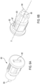
- FIGs. 6A and 6B depict the lock barrel 600 of the latch assembly 104.
- the lock barrel 600 is rotatably mounted to the housing 300 and radially aligned with the opening 402 in the paddle 400.
- a shoulder 602 formed on the top end of the lock barrel 600 is seated on the front facing side 302 of the housing 300.
- the outer body of the lock barrel 600 is rotationally fixed with respect to the housing 300.
- the lock barrel 600 includes an internal cylinder 603 which is capable of rotating with respect to the housing 300 and the outer body of the lock barrel 600.
- a post 604 extends from the internal cylinder 603 and is capable of rotating along with the internal cylinder 603.
- the lock barrel 600 is a solid body with the exception of a series of internal wafers 607 that are configured to be extended and retracted in a transverse direction with respect to the cylinder 603.
- the post 604 extends from the rear surface of the lock barrel 600.
- the post 604 is capable of rotating about the central axis B of the lock barrel 600 when the proper key (not shown) is inserted in the keyhole 605 of the internal cylinder 603 and rotated within the internal cylinder 603 of the lock barrel 600, as is known in the art.
- a crescent-shaped recess 606 is formed on the rear end of the lock barrel 600 at a location adjacent the post 604. In assembled form, the post 514 of the rotor 500 is moveably seated within the recess 606.
- the internal lock cylinder 603 is configured to be moved between unlocked and locked states using a key, as is known in the art.
- the paddle 400 In the locked state of the lock barrel 600, the paddle 400 is prevented from rotating about axis A from the home state shown in FIG. 1A .
- Installing the key causes the wafers 607 to retract and disengage from the housing 300, which permits the lock barrel 600 to be rotated along with the key.
- the unlocked state the paddle 400 can be rotated both to and from the home state shown in FIG. 1A by a user. It should be understood that in the home state of the paddle 400 shown in FIG. 1A , the pawls 112 and 114 are engaged with their respective strikers.
- the lock barrel 600 may be either locked or unlocked in the home state of the paddle 400.
- the lock barrel 600 may vary from that which is shown and described. By way of non-limiting example, the lock barrel 600 may be operated electronically. As another alternative, the lock barrel may be omitted from the latch assembly 104 in its entirety. If the lock barrel 600 is omitted then the paddle 400 will not require a hole 402. The geometry, position and structure of the post 604 may vary. The lock barrel 600 may be mounted to the paddle 400 (or other component) in a variety of ways.
- FIG. 7 depicts the torsion spring 700 of the latch assembly 104.
- the torsion spring 700 is connected to the paddle 400 for retaining the paddle 400 in the home position shown in FIG. 1A .
- the rear facing surface 405 ( FIG. 4B ) of the paddle 400 faces (and is parallel with) the front face 302 ( FIG. 3B ) of the housing 300.
- the torsion spring 700 includes a coiled body 702 having two free ends 704 and 706.
- the free ends 704 and 706 extend in opposite directions along separate axes that are each oriented parallel to the central axis of the coiled body 702.
- the coiled body 702 is positioned within a recess 303 ( FIG. 3B ) formed on the front face 302 of the housing 300.
- the end 704 of the spring 700 is positioned either within an aperture or against a surface of the recess 303 of the housing 300, whereas the other end 706 of the spring 700 is positioned against the rear facing surface 405 of the paddle 400.
- FIG. 8 depicts the torsion spring 800 of the latch assembly 104.
- the torsion spring 800 is connected to the rotor 500 for biasing the rotor 500 to a rotational position corresponding to the closed state of the latch assembly 104 (i.e., in which the pawls 112 and 114 are engaged with the strikers).
- the torsion spring 800 includes a coiled body 802 having two free ends 804 and 806.
- the free ends 804 and 806 extend in opposite directions along separate axes that are each oriented parallel to the central axis B of the coiled body 802.
- the coiled body 802 of the spring 800 is mounted within the annular recess 502 that is formed on the front side of the rotor 500, as described above.
- a bumper formed of a soft material may be seated between the rear face of the paddle 400 and the top surface of the housing 300 in order to limit sound generation upon moving the paddle to the home position.
- the lock barrel 600 is mounted in the recess 301 of the housing 300 such that the outer barrel 300 is fixed to the housing 300 while the lock cylinder 603 (and the post 604) are capable of rotating with respect to the housing 300.
- the coiled body 802 of the spring 800 is mounted over the cylinder 312 of the housing 300.
- the free end 806 of the spring 800 is then positioned within the slot 306 of the housing 300.
- the rotor 500 is then moved over the cylinder 312 of the housing 300.
- the free end 804 of the spring 800 is positioned into the recess 504 of the rotor 500.
- the rotor 500 is then rotated, thereby coiling the spring 800.
- the rotor 500 is continued to be moved over the cylinder 312 and rotated into position such that the barbs 316 of the housing 300 are eventually retained in the slots 506 of the rotor 500.
- the coiled body 702 of the spring 700 is positioned within the recess 303 ( FIG. 3B ) formed on the front face 302 of the housing.
- the end 704 of the spring 700 is positioned either within an aperture or against a surface of the recess 303 of the housing 300.
- the paddle 400 is then mounted to the housing 300 by positioning the ribs 310 within respective slots 404 of the paddle 400.
- the other end 706 of the spring 700 is positioned against the rear facing surface 404 of the paddle 400.
- the point at which the end 706 of the spring 700 contacts the paddle 400 is rearward of the axis A so as to bias the paddle 400 to the home position.
- a separate elastomeric element may be installed to act as a bumper between the housing and the underside of the paddle. This will serve to mitigate noise upon release of the paddle.
- lock barrel 600 may be installed last and installed once the entire assembly is installed and mounted in the door system. Applications can have the lock barrel installed near the end of the vehicle production line. This does not preclude the lock from being installed earlier and supplied as a complete unit but even in that case the lock would not likely be installed until after the paddle is installed.
- a pathway is created in the housing (near 309) that allows for access to the retention wafer on the lock cylinder.
- the latch assembly 104 is now assembled and ready for assembling onto the door 102 to form the door assembly 100.
- the latch assembly 104 (now assembled) is moved toward the opening 113 in the door 102 until the clip 307 of the housing 300 becomes snapped, clipped or otherwise engaged with the slot 122 ( FIG. 1B ). Thereafter, the rear face 304 of the housing 300 is placed against the front face of the door 102, and the pins 318 on the housing 300 are positioned with holes 130 ( FIG. 1B ) in the door 102. The fastener 109 is then moved from the rear side of the door 102 through the hole 117 of the door, and into the hole 309 at the rear face 304 of the housing 300. The fastener 109 is threadedly fastened to the hole 309 in the housing 300 thereby captivating the latch assembly 104 to the door 102.
- Assembly of the latch assembly 104 to the door 102 is achieved by the above-described snap engagement (by virtue of items 307 and 122) together with only a single fastener 109 engaged from the rear face of the door 102.
- This mounting scheme eases the assembly process as well as the accuracy of assembly.
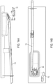
- the post 120 of the pawl 112 is mounted within the recess 510a of the rotor 500.
- the end 114a of the pawl 114 is then positioned through the opening in the clip 121 ( FIG. 1B ).
- the post 127 of the pawl 114 is then mounted within the recess 510b of the rotor 500.
- the posts 120 and 127 can be inserted into their respective recesses 510 from two different directions that are orthogonal to one another. More particularly, as shown in FIG. 14A , the posts 120 and 127 may be inserted into their respective recesses 510 in the front-rear direction. As shown in FIG. 14B , the posts 120 and 127 may be inserted into their respective recesses 510 in the right-left direction via the opening 511. The mated orientation of the posts 120 and 127 in their respective recesses 510 prevents the posts 120 and 127 from inadvertently become detached from their recesses 510.
- the guide segment 123 of the pawl 114 rests on the free end of the projection 119 on the door 102.
- the door assembly 100 is now assembled and ready for operation. It should be understood that the above description of assembling the latch assembly 104 and the door assembly 100 is not limited to any step or sequence of steps, and may vary from that which is described without departing from the scope and spirit of the invention.
- the paddle 400 is prevented from pivoting outwardly from its home position shown in those figures because the lock barrel 600 is maintained in the locked state. More particularly, as best shown in FIG. 9C , the paddle 400 is prevented from pivoting outward because the post 604 of the lock barrel 600 is positioned against the end 515a of the crescent-shaped opening 515 of the rotor 500.
- FIGs. 10A, 10B, 10C and 12A a user inserts a key into the keyhole 605 of the lock barrel 600 and rotates the lock cylinder 603 (see arrow in FIG. 10C ) thereby converting the lock barrel 600 from a locked state to an unlocked state, as is known in the art. Compare the orientations of the keyhole 605 in FIGs. 9A and 10A . As best shown in FIG. 10C , unlocking the lock cylinder 603 causes the post 604 of the lock barrel 600 to move away from the end 515a of the opening 515 of the rotor 500 and become centered (or substantially centered) within the opening 515.
- the latch assembly 104 is still in the closed position, however, the rotor 500 is now capable of rotating in the counter clockwise direction because the post 604 no longer abuts the end 515a of the opening 515 of the rotor 500.
- the door assembly 100 In the closed position of the latch assembly 104, the door assembly 100 cannot be moved with respect to the opening of the motor vehicle to which the door assembly 100 is mounted without rotating the paddle 400, as will be described hereinafter.
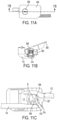
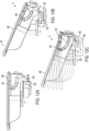
- FIGs. 11A, 11B, 11C and 12B to move the latch assembly 104 to the open position, the user then rotates the paddle 400 in the outward direction about axis A (see arrow in FIG. 12B ) against the bias of the spring 700.
- the slots 404 slide over their respective ribs 310 of the housing 300.
- the paddle 400 rotates relative to the lock barrel 600.
- the rounded leg 420 of the paddle 400 bears on the bearing surface 520 of the rotor 500 thereby urging the rotor 500 to rotate in the counterclockwise direction, as viewed from the rear of the latch assembly in FIG. 11C .
- the rotor 500 is free to rotate against the bias of the spring 800 in the counterclockwise direction since the post 604 is spaced from the end 515a of the opening 515 of the rotor 500.
- the slots 506 of the rotor 500 travel over the prongs 314 of the housing 300.
- the pawls 112 and 114 are moved inwardly (compared distances D1 and D2 in FIGs. 10B and 11B ) toward the housing 300.
- the prongs 125 FIG. 13D
- the posts 120 and 127 may rotate relative to their respective recesses 510 of the rotor 500.
- Rotation of the paddle 400 and rotor 500 to the open position is ceased once (i) the prongs 314 bear on the ends of their respective slots 506, (ii) the ribs 310 bear on the ends of their respective slots 404, and/or (iii) the posts 407 on the paddle 400 contact the shoulder 317 on the housing 300.
- the leg 420 of the paddle 400 remains in contact with the bearing surface 520 of the rotor 500 to avoid becoming detached from the rotor 500.
- the door assembly 100 may be moved with respect to the opening of the motor vehicle to which the door assembly 100 is mounted.
- the spring 700 returns the paddle 400 to the home position shown in FIG. 12A .
- the spring 800 causes the rotor 500 to rotate in the clockwise direction back to its starting position shown in FIG. 10C .
- the spring 800 also cause the paddle to return to the home position due to the engagement between the leg 420 and the bearing surface 520.
- the pawls 112 and 114 move outwardly and away from the housing 300 so that the ends 112a and 114a of the pawls 112 and 114, respectively, can engage with strikers (not shown) on the opening of the motor vehicle to which the door assembly 100 is mounted.
- the lock barrel 600 is still in the unlocked state at this stage.
- the user can insert a key into the keyhole 605 of the lock barrel 600 (if not already inserted) and rotate the lock cylinder 603 thereby converting the lock barrel 600 from the unlocked state to the locked state, as is known in the art.
- Locking the lock cylinder 603 causes the post 604 of the lock barrel 600 to move toward and bear on the end 515a of the opening 515 of the rotor 500, thereby preventing the rotor 500 from being rotated in the counter clockwise direction and the latch assembly 104 from being opened.
- the pawls, the paddle, and the rotor are all locked in position and prevented from rotation. This feature provides improved security and performance under impact conditions and may reduce BSR (bump, squeak and rattle).
- the guide section 123 of the pawl 114 limits unintended deflection travel of the pawl 114 with respect to the door 102. More particularly, the prongs 125 of the guide section 123 squeeze the sides of the free end 131 of the projection 119, as shown in FIG. 13D to either limit or prevent the pawl 114 from deflecting along the axis F (see FIG. 13D ).
- the prong 126 of the guide section 123 is a hard stop that interacts with the recess 133 formed at the free end 131 of the projection 119 to either limit or prevent the pawl 114 from deflecting downward along the axis G (see FIG. 13C ).
- the prongs 125 and 126 can flex to accommodate a limited amount of deflection.
- the prongs 125 and 126 are configured to help mitigate vibration and noise in the pawl 114 by limiting motion of and deflection of the pawl 114 under vibration.
- FIGs. 15A through 24B A second embodiment of a door assembly 900 incorporating aspects of the present invention is illustrated in FIGs. 15A through 24B .
- the door assembly 900 is both structurally and functionally similar to the door assembly 100 of FIGs. 1A through 1C , and only the differences between those door assemblies will be described hereinafter.
- the pawls of the door assembly 900 and the projections on the door 902 for supporting the pawls are not shown.
- a latch assembly 904 of the door assembly 900 is mounted to the door 902 to releasably retain the door 902 in the closed position.
- FIG. 16 depicts an exploded view of the latch assembly 904 of the door assembly 900.
- the primary components of the latch assembly 904 are a base housing 910, a user-operated paddle 912, a rotor 914, torsion springs 916 and 918, a lock barrel 920 and, optionally, two pawls (not shown).
- the base housing 910 which is shown in FIGs. 17A-17G , is similar to the housing 300 and only the primary differences between those housings will be described hereinafter.
- One alignment pin 930 protrudes from the rear face 932 of the housing 910. The pin 930 is aligned along the centerline of the housing 910. The pin 930 is configured to be inserted into a hole 934 ( FIG. 15B ) disposed in the door 902 for alignment purposes.
- Two prongs 936 also protrude from the rear face 932 of the housing 910 on the same end of the rear face 932 as the pin 930.
- the prongs 936 are positioned on opposite corners of the rear face 932.
- Each prong 936 includes a barb at its free end, and is configured to be snapped into a recess 938 ( FIG. 15B ) disposed in the door 902 for retention purposes prior to mounting the base housing 910 to the door 902 using a fastener 993 (not shown in this view, but is shown in FIG. 25B ).
- the fastener is guided through a hole 940 in the door 902 and is threaded into a hole 942 in the housing 910 for securing the base housing 910 (and the entire latch assembly 904) to the door 902.
- the fastener may be eliminated from the assembly and the unit may be retained in the door through use of only the prongs.
- a clip 944 in the form of a flexible tab or prong, is formed on one side of the housing 902 and extends outwardly from that side of the housing 902.
- a rib 946 extends outwardly along the centerline of the clip 944.
- the clip 944 is configured to be inserted into a recess 948 formed on the side of the rectangular recessed region 949 of the door 902.
- the top end of the recess 948 includes a channel 950 for receiving the rib 946 of the clip 944. Engagement between the rib 946 and the channel 950 is used as a location feature during assembly of the latch assembly 904 onto the door 902.
- Pins 954 project from opposing side walls 958 and 959 of the housing 910.
- the pins 954 are sized to be received in blind channels 955 (see FIG. 18B ) formed in the paddle 912.
- a thru-hole 956 is formed through the side walls 958 and 959 of the housing 910 for receiving a pin 960.
- the pin 960 has an annular relief (or cutout) 962 formed in a central region thereof.
- a projection 964 that extends from an interior surface of the housing 910 is seated within the relief 962 of the pin 960.
- Engagement between the projection 964 of the housing 910 and the relief 962 of the pin 960 retains the pin 960 within the thru-hole 956 of the housing 910.
- the pin 960 is positioned through the center of the coiled body of the spring 916 for biasing the paddle 912 to the home position.
- the pin 960 may also be retained by other methods not described herein.
- a hole 970 is formed through the housing 910 for receiving the lock barrel 920.
- Two inwardly extending ramped projections 972 are positioned at diametrically opposite positions along the inner circumference of the hole 970. The projections 972 engage surfaces on the lock barrel 920 and are configured to secure the lock barrel 920 within the hole 970, while permitting rotation of the lock barrel 920 within the hole 970.
- the use of the two inwardly extended projections 972 may be altered both in number and in style as needed to accommodate the specifics of the lock cylinder design.
- the paddle 912 which is shown in FIGs. 18A-18G , is similar to the paddle 400 and only the primary differences between those paddles will be described hereinafter.
- the paddle 912 includes opposing side walls 973 and 974.
- An arc-shaped blind channel 955 is defined on each side wall 973 and 974, and each channel 955 is sized for receiving one of the pins 954 on the housing 910.
- Another arc-shaped channel 976 is defined on each side wall 973 and 974, and each channel 976 is sized for receiving one end of the pin 960.
- the pins 954 are inserted into the channels 955 until the hole 956 of the housing 910 is aligned with the arc-shaped channel 976. Thereafter, the pin 960 is inserted through the channels 976 and the hole 956 until the relief 962 of the pin 960 engages the projection 964 of the housing 910, thereby captivating the paddle 912 to the housing 910.
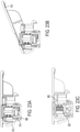
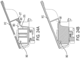
- the paddle 912 is capable of pivoting about the housing 910 between a closed position ( FIG. 22A ) and an open position ( FIG. 22B ).
- the channels 976 slide over the pin 960 while the channels 955 slide over the pins 954.
- the arc created the pivot is defined by two independent pins (per side of the paddle 912) riding in arc segments about the same center.
- the arcs of the channels 955 and 976 are concentric.
- the pin 960 bears on the end of the channels 976, and walls 977 ( FIG. 18B ) of the paddle 912 bear on the outer walls 979 ( FIG. 17B ) of the housing 910 at location 981, thereby preventing further rotation of the paddle 912 beyond the open position shown. Stated differently, in the open position of the paddle 912, further rotation of the paddle 912 is prevented by features at opposite ends of the housing 910.
- a bumper 983 which is formed from a soft material, such as rubber or plastic, is positioned within an aperture formed in the housing 910.
- the bumper 983 is also positioned to contact the underside of the paddle 912 in the closed position of the paddle 912.
- the bumper 983 reduces noise generated between the housing 910 and the paddle 912 when the paddle 912 is returned to the closed position, as shown in FIGs. 23A and 23C .
- housing and the bumper form a directed channel or pathway allowing for access to the lock retention wafer as described earlier.
- the rotor 914 which is shown in FIGs. 19A-19E , is similar to the rotor 500 and only the primary differences between those rotors will be described hereinafter.
- the rotor 914 includes a body 980 having a circular base wall 982.
- Two arc-shaped cutouts 984 surround the outer perimeter of the wall 982 at diametrically opposite positions.
- Each cutout 984 includes an enlarged opening 985 for receiving one of the barbs 986 of the housing 910.
- the barbs 986 are first positioned through respective enlarged openings 985 in the rotor 914 and the rotor 914 is rotated to space the barbs 986 away from their openings 985.
- the barbs 986 retain the rotor 914 to the housing 910.
- the barbs 986 and the attending cutouts 985 may be sized such that installation orientation may be controlled. In other words one barb and one attending cutout may be sized larger than the other pair to prevent installation in the incorrect orientation. Also, it may be possible to alter the number of barbs required for the installation.
- An annular wall 987 extends from the bottom side of the base wall 982, and an interior space 987a is defined within the annular wall 987 in which the distal end of the lock barrel 920 is positioned.
- a straight rib 988 is disposed on the lower side of the wall 982 and within the interior space 987a for interacting with the post 990 of the lock barrel 920, as will be described later.
- An annular channel 987b surrounds the wall 987 and is sized to receive the spring 918.
- the lock barrel 920 which is shown in FIGs. 20A and 20B , is similar to the lock barrel 600 and only the primary differences between those lock barrels will be described hereinafter.
- the lock barrel 920 includes a post 990 that extends from the internal cylinder 994 and is capable of rotating along with the internal cylinder 994 (like post 604).
- the post 990 has a rectangular shape in cross-section with a relief disposed therein.
- FIGs. 21A-21C in the unlocked and closed state of the latch assembly 904 shown in FIG. 21A , the post 990 of the lock barrel 920 is spaced apart (in the circumferential direction) from the rib 988 of the rotor 914. Thus, the paddle 912 and the rotor 914 are free to rotate toward the open position.
- the open and unlocked state of the latch assembly 904 shown in FIG. 21B the paddle 912 has been pivoted to the open position and the rotor 914 has been rotated by the paddle 912.
- the post 990 of the lock barrel 920 remains spaced apart (in the circumferential direction) from the rib 988 of the rotor 914.
- the post 990 of the lock barrel 920 has been rotated (i.e., by rotating the key in the lock barrel 920) such that the post 990 bears on the rib 988 of the rotor 914, thereby preventing counterclockwise rotation (as viewed in FIG. 21C ) of the rotor 914, which also prevents rotation of the paddle 912 toward the open position.
- FIGs. 25A through 31F A third embodiment of a door assembly 1000 incorporating aspects of the present invention is illustrated in FIGs. 25A through 31F .
- the door assembly 1000 is both structurally and functionally similar to the door assembly 900 of FIGs. 15A through 24B , and only the differences between those door assemblies will be described hereinafter.
- a non-locking latch assembly 1004 of the door assembly 1000 is mounted to the door 1002 to releasably retain the door 1002 in the closed position.
- the latch assembly 1004 of the door assembly 1000 is mounted to the door 1002 in the same fashion as the latch assembly 904.
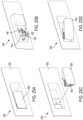
- FIG. 25C The sequence of assembling the latch assembly 1004 onto the door 1002 is shown starting from FIG. 25C in which the latch assembly 1004 is moved toward the door 1102.
- FIG. 25D the latch assembly 1004 is toed (angled) and brought together with the door 1002 and the clip 944 of the latch is positioned within the recess 948 in the door 1002, as described above.
- FIG. 25A the latch assembly 1004 is rotated into the recess of the door 1002 until the clips on the latch assembly 1004 connect into their respective openings in the door 1002.
- FIG. 25B the fastener 993 is mounted to the door 1002 and the latch assembly 1004.
- FIGs. 26A-26E depict the latch assembly 1004 and two pawls 1006 and 1008 mounted to the latch assembly 1004.
- the pawls 1006 and 1108 operate in substantially the same fashion as the pawls of the latch assembly 104.
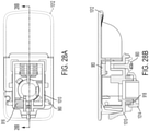
- FIGs. 27-28B depict the non-locking latch assembly 1004 of the door assembly 1000.
- the primary components of the latch assembly 1004 are a base housing 1010, a user-operated paddle 1012, a rotor 1014, torsion springs 916 and 918, and, optionally, two pawls 1006 and 1008 (not shown in this view).
- the common features between latch assembly 1004 and latch assembly 904 will not be described herein.
- the paddle 1012 which is shown in FIGs. 29A-29F , is substantially similar to the paddle 912 with the exception that the paddle 1012 includes a square shaped opening 1015 on a side face thereof.
- the opening 1015 is used with a deadbolt in the locking version of the latch assembly 1100 that is shown in the fourth embodiment of FIGs. 32-38 .
- the opening 1015 in the paddle 1012 may be replaced with a blind pocket, ledge or bearing surface against which the deadbolt can bear without departing from the scope of the invention.
- the third embodiment is non-locking and the opening 1015 does not serve any particular purpose for the non-locking embodiment.
- the base housing 1010 which is shown in FIGs. 30A-30F , is substantially similar to the housing 910 with the exception that the housing 1010 includes a square shaped opening 1016 on a side face thereof.
- the square shaped opening 1016 is used with the deadbolt in the locking version of the latch assembly 1100 that is shown in the fourth embodiment of FIGs. 32-38 .
- the opening 1018 in the housing 1010 is sized to receive a different style of lock barrel in the locking version of the latch assembly (only).
- Two outwardly protruding ramps 1020 and 1022 are defined on the top and bottom sides of the housing 1010. The radius of curvature of the ramp 1022 is less than that of the ramp 1020.
- Each ramp 1020 and 1022 is configured to interact with a surface or depression that is formed on the interior sides of the paddle 1012 to help guide rotation of the paddle 1012 about the base housing 1010.
- a slot 1011 is formed on the base wall of the housing 1010 for retaining a spring tab, as will be described with reference to the locking version of the latch assembly 1100 that is shown in the fourth embodiment of FIGs. 32-38 .
- the rotor 1014 which is shown in FIGs. 31A-31F , is substantially similar to the rotor 914 with the exception that rotor 1014 does not include an internal rib (like rib 988) that is configured to interact with a lock.
- the user rotates the paddle 1012 in the outward direction against the bias of the spring 916 to the extended position shown in FIG. 25D .
- the paddle 1012 operates in the same manner as that described with reference to the second embodiment.
- the rounded leg 1020 of the paddle 1012 bears on the bearing surface 1022 of the rotor 1014 thereby urging the rotor 1014 to rotate in the counterclockwise direction (as viewed from the rear of the latch assembly in FIG. 25B ) against the bias of the spring 918.
- the slots 1024 of the rotor 1014 travel over the prongs 1026 of the housing 1010.
- the pawls 1006 and 1008 are moved inwardly toward the housing 1010 and separate from their respective strikers in the vehicle dashboard.
- the door assembly 1000 In the open position of the latch assembly 1004, the door assembly 1000 may be moved with respect to the opening of the motor vehicle to which the door assembly 1000 is mounted.
- the spring 916 causes the paddle 1012 to return to the home position shown in FIGs. 25A and 28B .
- the spring 918 causes the paddle 1012 to return to the home position due to the bearing engagement between the leg 1020 and the bearing surface 1022 of the rotor 1014.
- the paddle 1012 comes to rest on the bumper 983 to prevent BSR, as described above.
- the pawls 1006 and 1008 move outwardly and away from the housing 1010 so that the free ends of the pawls 1006 and 1008, respectively, can engage with strikers (not shown) on the opening of the motor vehicle to which the door assembly 1000 is mounted.
- the user then closes the door assembly 1000, thereby concealing the opening in the motor vehicle and causing the free ends of the pawls 1006 and 1008, respectively, to engage with strikers (not shown) on the opening of the motor vehicle.
- FIGs. 32 through 38 A fourth embodiment of a locking latch assembly 1100 incorporating aspects of the present invention is illustrated in FIGs. 32 through 38 .
- the locking latch assembly 1100 can be used with the door 1002 of FIG. 25A .
- the latch assembly 1100 is both structurally and functionally similar to the non-locking latch assembly 1004 of FIGs. 25A through 31F , with the overall exception that the latch assembly 1100 is configured to lock the door 1002 in the closed position.
- the locking latch assembly 1100 generally includes all of the components of the latch assembly 1004, and, additionally, an electronic lock 1102 for selectively locking and unlocking the latch assembly 1100, and a deadbolt 1104 that is moved by the lock 1102 against the bias of a spring tab 1106 between locked and unlocked positions.
- the electronic lock 1102 comprises a motor housing 1110 containing an electric motor having an output shaft 1111.
- a gear 1112 having a number of gear teeth is non-rotatably connected to the output shaft 1111 of the motor in a keyed fashion such that the gear 1112 rotates along with the output shaft 1111.
- the motor housing 1110 is fixed in the hole 1018 in the housing 1010 by spring tabs 1019 defined in the interior of the housing 1010.
- the electronic lock 1102 includes electrical wires for connection to a power source in the vehicle (e.g., the vehicle battery).
- the rotor 1014 has a central opening 1025 through which the wires can pass.
- the electronic lock 1102 or a receiver unit that is connected thereto is configured to receive commands wirelessly (e.g., short range radio transmission, Bluetooth, RFID, etc.) from a key fob having a transmitter (for example), however, the lock 1102 could also receive commands through a wired connection in the vehicle.
- the lock 1102 could also be electrically controlled using a simple switch.
- the lock 1102 is not visible from the exterior of the door assembly.
- the lock 1102 is also referred to more broadly herein as an "actuator,” because the lock 1102 may be a button or lock cylinder that is manually actuated.
- the motor of the lock 1102 has a large gear ratio (e.g., 100:1) such that that the system cannot be back driven. More particularly, the large gear ratio prevents the deadbolt 1104 from being manually pushed backwards into the housing 1010 in order to unlock the latch assembly 1100 in a manual and unauthorized manner.
- a large gear ratio e.g. 100:1
- the deadbolt 1104 which is shown in FIGs. 37A through 37F , is an elongated body having a square or rectangular cross-section, at least in part.
- the deadbolt 1104 includes an axially extending first end 1113 having a triangular shaped gear tooth 1116 on side that faces the gear 1112.
- the gear tooth 1116 is configured to be meshed with the gear 1112 of the lock 1102.
- An axially extending second end 1118 is parallel and spaced apart from the first end 1113.
- a shoulder 1115 extends transversely between the ends 1113 and 1118.
- Two parallel prongs 1117 extend the shoulder 1115 at the intersection of the shoulder 1115 and the first end 1113 in a direction that is transverse to the first end 1113.
- the second end 1118 of the deadbolt 1104 is configured to retain the latch assembly 1100 in a locked configuration when the deadbolt 1104 is moved to the extended and locked position shown in FIGs. 34A and 34B .
- the second end 1118 is positioned at least partially through both the hole 1016 in the housing 1010 and the hole 1015 in the paddle 1012.
- the second end 1118 of the deadbolt 1104, the hole 1016 in the housing 1010 and the hole 1015 in the paddle 1012 are all axially aligned.
- the spring tab 1106 is shown in FIG. 38 , and is composed of a thin flexible and elastic material, such as metal or plastic.
- the spring tab 1106 comprises an elongated body having a first end 1120 that is fixedly mounted in the slot 1011 formed in the housing 1010, and a second end 1121 opposite the first end 1120. The second end 1121 is folded over itself and a gap is formed between the fold. In assembled form, as best shown in FIG. 33E , the second end 1121 of the spring tab 1106 is mounted to the prongs 1117 of the deadbolt 1104.
- the spring tab 1106 is configured to bias the moveable deadbolt 1104 with respect to the stationary housing 1010.
- the spring tab 1106 is biased to center the deadbolt 1104 between the locked and unlocked positions shown in FIGs. 34B and 35B , respectively.
- the spring tab 1106 does not have to be a separate component, and could be co-molded and integral with the housing 1010 or the deadbolt 1104. Also, the spring could take on other forms such as a wound spring or a torsional spring.
- FIGs. 33A through 33E depict the sequential process of assembling the lock 1102, deadbolt 1104, spring tab 1106 and bumper 983 into the latch assembly 1100.
- the second end 1118 of the deadbolt 1104 is positioned through the hole 1016 in the housing 1010 and at least partially through the hole 1015 in the paddle 1012, thereby preventing the paddle 1012 from being rotated by a user with respect to the housing 1010.
- the user then transmits a signal to the lock 1102, which causes the motor of the lock 1102 to rotate the gear 1112 in a clockwise direction (as viewed in FIG. 34A ) which translates the deadbolt 1104 out of the hole 1015 of the paddle 1012 against the bias of the spring tab 1106, as depicted in FIG. 35A .
- the latch assembly 1100 is maintained in the unlocked position. The user can then rotate the paddle 1012 to open the door 1002, as is described with reference to the third embodiment.
- the user transmits a signal to the lock 1102, which causes the motor of the lock 1102 to rotate the gear 1112 in a counterclockwise direction (as viewed in FIG. 34A ) which translates the deadbolt 1104 into the hole 1015 of the paddle 1012 against the bias of the spring tab 1106, as depicted in FIG. 34B .
- the deadbolt 1104 is positioned within the hole 1015 of the paddle 1012, the latch assembly 1100 is maintained in the locked position.
- the lock 1102 and the deadbolt 1104 are decoupled from the pawls 1006 and 1008 and the rotor 1014 such that the pawls 1006 and 1008 are capable of translating even when the paddle 1012 is locked by the deadbolt 1104. Accordingly, the door 1002 can be moved to the closed position even while the latch assembly 1100 is locked. This feature prevents breakage of the latch assembly 1100 if the door 1002 is closed while the latch assembly 1100 is locked.
- the deadbolt 1104 has a limited number of teeth (e.g., one) such that at the moment when the deadbolt 1104 has reached either the locked or unlocked position, the gear tooth 1116 is not meshed with the gear 1112.
- the gear 1112 can continue to rotate without causing damage to either the gear 1112 or the deadbolt 1104.
- the spring tab 1106 pulls the deadbolt 1104 toward the center of the gear 1112 to engage the tooth 1116 with the teeth of the gear 1112. Accordingly, when the drive direction of the gear 1112 is reversed, the deadbolt 1104 and gear 1112 engage so that the deadbolt 1104 can be moved in the opposite direction.
- the biasing of the spring tab 1106 also serves as a protection against gear stripping or motor stalling.
- the ability for the tooth 1116 on the deadbolt 1104 to disengage from the gear 1112 on the motor prevents an overload condition at end of stroke for the deadbolt 1104.
- the spring tab 1106 ensures reengagement of the tooth 1116 to the gear 1112 for reverse actuation as needed.
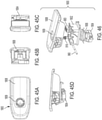
- FIGs. 45A-45D and 46 depict a fifth exemplary embodiment of a locking latch assembly 1800 for use with a door assembly, such as the door assembly of FIGs. 25A-25D (or similar).
- the locking latch assembly 1800 is substantially similar to the latch assembly 1100 of FIG. 32 and only the primary differences therebetween will be described hereinafter.
- the common components between those latch assemblies share the same reference characters.
- the paddle 1808 of the latch assembly 1800 includes an aperture 1809 through which a lock barrel (not shown) is positioned for either locking or unlocking the latch assembly 1800. Further details regarding the lock barrel are described with reference to FIGs. 6A and 6B .
- FIGs. 47-52 depict an exemplary sequence for assembling the torsion spring 1806, rotor 1804 and base housing 1802 of the latch assembly 1800 of FIG. 45A .
- the spring 1806 is mounted to the rotor 1804 by positioning the coiled portion of the spring 1806 into an annular recess 1810 formed on one side of the rotor 1804.
- One free end 1811 of the spring 1806 is positioned into a first spring mounting recess 1812 that extends tangentially from the annular recess 1810.
- the other free end 1813 of the spring 1806 is wound about the rotor 1804, thereby tightening the coiled portion of the spring 1806, and is inserted into a second spring mounting recess 1814 that is formed on a side surface of the rotor 1804.
- the rotor 1804 and the spring 1806 now constitute a sub-assembly.
- the sub-assembly of the rotor 1804 and the spring 1806 are mounted to the underside of the base housing 1802 by positioning barbs 1816 on the housing 1802 into respective slots 1818 formed in the rotor 1804, much like the connection between the barbs and slots of FIG. 11C .
- the rotor 1804 is rotated in the direction depicted by the arrow until one of the barbs 1816 on the housing 1802 snaps over a protruding surface 1820 formed on the rotor 1804. Thereafter, the sub-assembly of the rotor 1804 and the spring 1806 are rotatably connected to the housing 1802.
- the free end 1813 of the spring 1806 is positioned against a stop 1822 formed on an exterior surface of the housing 1802.
- the spring 1806 biases the rotor 1804 to rotate in a direction that is opposite to the direction of the arrow shown in FIG. 52 .
- the base housing 1802 of the locking latch assembly 1800 includes rotation limiters 1840 extending from axial sides thereof.
- Each rotation limiter 1840 is a surface that is configured to engage with respective surfaces 1842 formed on the paddle 1808 to limit rotation of the paddle 1808 beyond the open position shown in FIG. 54B .
- Surfaces 1842 on paddle are heel shaped and are concealed from view within the interior of the hollow paddle 1808. It is noted that other components of the locking latch assembly 1800, acting in concert with the rotation limiters 1840, may also prevent rotation of the paddle 1808 beyond the open position shown in FIG. 54B .
- FIG. 55 is a bottom plan view of a sixth exemplary embodiment of a locking latch assembly 1900 for use with the door assembly of FIGs. 25A-25D
- the latch assembly 1900 is substantially identical to the latch assembly 1800 of FIG. 45A and only the primary differences therebetween will be described hereinafter.
- the rotor 1902 of the latch assembly 1900 includes four crescent shaped recesses 1904a through 1904d (referred to either individually or collectively as recess(es) 1904) defined on the perimeter of the rotor 1900.
- Recesses 1904a-1904d are evenly spaced apart by approximately ninety degrees about the perimeter of rotor 1902.
- Each recess 1904 is configured to be releasably coupled to one of the posts 120 and 127 of the pawls 112 and 114, respectively, for example, as was described above with respect to FIG. 5B .
- recesses 1904a and 1904b can be found on the rotor 1804 of the latch assembly 1800, however, unlike the rotor 1804, the rotor 1902 additionally includes two further two recesses 1904c and 1904d.
- the recesses 1904c and 1904d are provided as an alternative to using recesses 1904a and 1904b. More particularly, when it is desired to utilize the locking latch assembly 1900 in a "side-pull" arrangement (like that shown in FIG. 1A ) the two pawls are connected to recesses 1904a and 1904b. Alternatively, when it is desired to utilize the locking latch assembly 1900 in a "vertical-lift" arrangement, as shown in FIGS.
- the two pawls 1908 are connected to recesses 1904c and 1904d.
- the pawls are shown mounted to (only) the recesses 1904c and 1904d, and the pawls are shown rotating the rotor 1902 in those views.
- the number of recesses 1904 and the spacing therebetween can vary.
- the rotor 1902 may only include two recesses 1904, and the orientation of the pawls may be changed to switch between the vertical-lift and side-pull arrangements.
- any of the latch assemblies shown herein can be employed in either a side-pull configuration or a vertical-lift configuration.
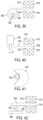
- FIGs. 39-44 depict alternative arrangements for an actuator that moves a deadbolt or a deadbolt-like member.
- FIG. 39 depicts a schematic view of an alternative arrangement for locking the paddle 1012 of the locking latch assembly of FIG. 32 , wherein the alternative arrangement comprises a motor driven clock spring 1200.
- the clock spring 1200 is wound or unwound by the shaft 1202 of a motor.
- the end 1204 is positioned through the opening 1016 of the housing 1010 and at least partially through the opening 1015 of the paddle 1012, thereby locking the paddle 1012 in a fixed position.
- Rotating the shaft 1202 of the motor in the opposite direction withdrawals the end 1204 of the paddle 1012 from the opening 1015 of the paddle 1012, thereby releasing and unlocking the paddle 1012.
- the locked position of the paddle 1012 is shown.
- FIG. 40 depicts a schematic view of an alternative arrangement for locking the paddle 1012 of the locking latch assembly of FIG. 32 , wherein the alternative arrangement comprises a motor driven eccentric member 1302.
- the eccentric member 1302 is rotated by the shaft 1202 of a motor 1304 to which it is non-rotatably mounted.
- the eccentric member 1302 is rotated such that the eccentric portion 1306 having a large diameter is positioned through the opening 1016 of the housing 1010 and at least partially through the opening 1015 of the paddle 1012, thereby preventing the paddle 1012 from moving with respect to the housing 1010.
- the eccentric member 1302 is rotated such that the eccentric portion 1306 having a large diameter is separated from the opening 1015 of the paddle 1012, thereby permitting the paddle 1012 to move with respect to the housing 1010.
- FIG. 41 depicts an alternative motor driven eccentric member for the arrangement of FIG. 40 comprising a motor driven crescent cam 1402.
- the crescent cam 1402 is driven by a gear 1404.
- the crescent cam 1402 replaces the eccentric member 1302 shown in FIG. 40 , and the gear 1404 can be connected to the motor 1304 of FIG. 40 .
- FIG. 42 depicts a schematic view of yet another alternative arrangement for locking the paddle of the locking latch assembly of FIG. 32 , wherein the alternative arrangement comprises a motor driven rack and pinion.
- a gear 1502 which is powered by the output shaft of a motor (not shown) is engaged with the gear teeth 1505 on a top rack 1504, and the gear teeth on a bottom rack 1506.
- the bottom rack 1506 is optional.
- the gear 1502 is rotated such that the top rack 1504 moves through the opening 1016 of the housing 1010 and at least partially through the opening 1015 of the paddle 1012, thereby preventing the paddle 1012 from moving with respect to the housing 1010.
- the gear 1502 is rotated in the opposite direction such that the top rack 1504 moves out of the opening 1015 of the paddle 1012, thereby permitting the paddle 1012 to move with respect to the housing 1010.
- FIG. 43 depicts a schematic view of yet another alternative arrangement for locking the paddle of the locking latch assembly of FIG. 32 , wherein the alternative arrangement comprises a motor driven and spring loaded rack and pinion.
- a gear 1602 which is powered by the output shaft of a motor (not shown) is engaged with the gear teeth 1605 on the lower surface of a rack 1604.
- the rack 1604 is biased to a central position by two springs 1608a and 1608b that bias the rack 1604 in opposing directions.
- One end of each spring 1608a and 1608b is mounted to the rack 1604 and the opposite end of each spring 1608a and 1608b is mounted to a stationary and fixed point.
- the gear 1602 is rotated such that the rack 1604 moves through the opening 1016 of the housing 1010 and at least partially through the opening 1015 of the paddle 1012 against the bias of the spring 1608a, thereby preventing the paddle 1012 from moving with respect to the housing 1010.
- the gear 1602 is rotated in the opposite direction such that the rack 1604 moves out of the opening 1015 of the paddle 1012 against the bias of the spring 1608b, thereby permitting the paddle 1012 to move with respect to the housing 1010.
- the length 1609 of the rack 1604 on either side of the teeth 1605 is free of teeth to prevent damage to the rack 1604.
- FIG. 44 depicts a schematic view of yet another alternative arrangement for locking the paddle of the locking latch assembly of FIG. 32 .
- the arrangement shown in FIG. 44 is substantially the same as the arrangement shown in FIG. 43 with the exception that the arrangement shown in FIG. 44 is biased by flexible living springs 1702a and 1702b. More particularly, living springs 1702a and 1702b extend from the top surface of the rack 1701. The interaction between the living springs 1702a and 1702b and the stationary posts 1704a and 1704b, respectively, centers the rack 1701. More particularly, when the gear 1705 rotates the rack 1701 toward the locked position, the living spring 1702b deflects against the stationary post 1704b, and when the gear 1705 is rotated in the opposite direction, the living spring 1702b returns to its initial form. Conversely, when the gear 1705 rotates the rack 1701 toward the unlocked position, the living spring 1702a deflects against the stationary post 1704a, and when the gear 1705 is rotated in the opposite direction, the living spring 1702a returns to its
Landscapes
- Engineering & Computer Science (AREA)
- Mechanical Engineering (AREA)
- Lock And Its Accessories (AREA)
- Vehicle Step Arrangements And Article Storage (AREA)
Applications Claiming Priority (4)
| Application Number | Priority Date | Filing Date | Title |
|---|---|---|---|
| US201862651998P | 2018-04-03 | 2018-04-03 | |
| US201862679401P | 2018-06-01 | 2018-06-01 | |
| EP19718527.5A EP3775453B1 (de) | 2018-04-03 | 2019-04-02 | Verriegelung für fahrzeughandschuhfach |
| PCT/US2019/025404 WO2019195303A2 (en) | 2018-04-03 | 2019-04-02 | Vehicle glove box latch |
Related Parent Applications (2)
| Application Number | Title | Priority Date | Filing Date |
|---|---|---|---|
| EP19718527.5A Division-Into EP3775453B1 (de) | 2018-04-03 | 2019-04-02 | Verriegelung für fahrzeughandschuhfach |
| EP19718527.5A Division EP3775453B1 (de) | 2018-04-03 | 2019-04-02 | Verriegelung für fahrzeughandschuhfach |
Publications (2)
| Publication Number | Publication Date |
|---|---|
| EP3954848A2 true EP3954848A2 (de) | 2022-02-16 |
| EP3954848A3 EP3954848A3 (de) | 2022-06-08 |
Family
ID=66223842
Family Applications (3)
| Application Number | Title | Priority Date | Filing Date |
|---|---|---|---|
| EP19718527.5A Active EP3775453B1 (de) | 2018-04-03 | 2019-04-02 | Verriegelung für fahrzeughandschuhfach |
| EP21189197.3A Pending EP3954848A3 (de) | 2018-04-03 | 2019-04-02 | Verriegelung für handschuhfach eines fahrzeugs |
| EP21189205.4A Pending EP3936690A3 (de) | 2018-04-03 | 2019-04-02 | Verriegelung für handschuhfach eines fahrzeugs |
Family Applications Before (1)
| Application Number | Title | Priority Date | Filing Date |
|---|---|---|---|
| EP19718527.5A Active EP3775453B1 (de) | 2018-04-03 | 2019-04-02 | Verriegelung für fahrzeughandschuhfach |
Family Applications After (1)
| Application Number | Title | Priority Date | Filing Date |
|---|---|---|---|
| EP21189205.4A Pending EP3936690A3 (de) | 2018-04-03 | 2019-04-02 | Verriegelung für handschuhfach eines fahrzeugs |
Country Status (6)
| Country | Link |
|---|---|
| US (2) | US11814881B2 (de) |
| EP (3) | EP3775453B1 (de) |
| JP (5) | JP7315577B2 (de) |
| KR (1) | KR102803722B1 (de) |
| CN (3) | CN114856329B (de) |
| WO (1) | WO2019195303A2 (de) |
Families Citing this family (9)
| Publication number | Priority date | Publication date | Assignee | Title |
|---|---|---|---|---|
| EP3728771A1 (de) * | 2017-12-21 | 2020-10-28 | Southco, Inc. | Türverriegelung |
| KR102830765B1 (ko) * | 2018-10-18 | 2025-07-07 | 가부시키가이샤 파이오락꾸스 | 개폐체의 잠금 장치 |
| US11359420B2 (en) * | 2019-05-29 | 2022-06-14 | GM Global Technology Operations LLC | Pivoted lockable latch actuator |
| GB2605311B (en) * | 2019-12-10 | 2023-09-13 | Piolax Inc | Rotation member connecting structure and method for manufacturing said structure |
| WO2022050177A1 (ja) * | 2020-09-03 | 2022-03-10 | 株式会社パイオラックス | 開閉体のロック装置 |
| WO2022181030A1 (ja) * | 2021-02-25 | 2022-09-01 | 株式会社パイオラックス | ロッドおよびそのロッドを備えるロック装置 |
| JP2024520800A (ja) * | 2021-06-11 | 2024-05-24 | サウスコ,インコーポレイティド | グローブボックスラッチ用の爪コネクタ |
| US12209444B2 (en) * | 2021-11-26 | 2025-01-28 | Embraer S.A. | Universal latch assembly to allow selective latch handle orientations |
| JP2024112618A (ja) * | 2023-02-08 | 2024-08-21 | 日本プラスト株式会社 | ロック装置及び収納装置 |
Family Cites Families (72)
| Publication number | Priority date | Publication date | Assignee | Title |
|---|---|---|---|---|
| US4212415A (en) * | 1978-01-09 | 1980-07-15 | Refreshment Machinery Incorporated | Housing and module therefor |
| FR2527284A1 (fr) * | 1982-05-19 | 1983-11-25 | Neiman Sa | Dispositif de solidarisation en rotation |
| JPH0667742U (ja) * | 1993-03-01 | 1994-09-22 | タキゲン製造株式会社 | 埋め込みハンドル装置 |
| US5100015A (en) * | 1991-07-05 | 1992-03-31 | Electro-Wire Products, Inc. | Latch unit for container and mating lid |
| IT1267167B1 (it) * | 1994-11-25 | 1997-01-28 | Itw Fastex Italia Spa | Elemento di fissaggio in platica, in particolare elemento fermapannello utilizzabile su veicoli |
| KR100204655B1 (ko) * | 1995-10-09 | 1999-06-15 | 류정열 | 자동차용 글로브박스 |
| US6626472B1 (en) * | 1999-02-22 | 2003-09-30 | Southco, Inc. | Load floor latch |
| US6337541B1 (en) * | 1999-10-08 | 2002-01-08 | Robert G. Dickie | Electroluminescent lighting device |
| US6669243B2 (en) | 2001-07-03 | 2003-12-30 | Piolax Inc. | Side lock assembly for storage bin |
| JP3940318B2 (ja) | 2002-06-03 | 2007-07-04 | 株式会社パイオラックス | サイドロック装置 |
| US7695028B2 (en) | 2002-11-07 | 2010-04-13 | Piolax, Inc. | Lock apparatus |
| JP4148883B2 (ja) | 2002-12-18 | 2008-09-10 | 株式会社パイオラックス | グローブボックス用リッドロック装置 |
| KR100523576B1 (ko) | 2003-02-13 | 2005-10-25 | 현대모비스 주식회사 | 글로브박스의 스트라이커 장착 구조 |
| US7182373B2 (en) | 2003-04-17 | 2007-02-27 | Piolax, Inc. | Side lock apparatus for storages |
| US7383707B2 (en) | 2003-05-23 | 2008-06-10 | Piolax, Inc. | Storage locking apparatus |
| JP4355256B2 (ja) * | 2003-05-23 | 2009-10-28 | 株式会社パイオラックス | ロック装置 |
| JP4211713B2 (ja) * | 2003-09-05 | 2009-01-21 | トヨタ紡織株式会社 | 結合構造 |
| JP2005160222A (ja) * | 2003-11-26 | 2005-06-16 | Yazaki Corp | プロテクタのロック構造およびワイヤハーネス |
| DE112005001560B4 (de) * | 2004-06-30 | 2014-04-03 | Southco, Inc. | Bodenklappenverschluß |
| US7475929B2 (en) | 2004-09-15 | 2009-01-13 | Piolax Onc. | Lid open-close apparatus |
| US7878822B2 (en) * | 2004-12-10 | 2011-02-01 | Cooper Technologies Company | Sealed compact power distribution module |
| FR2882798A1 (fr) * | 2005-03-03 | 2006-09-08 | Valeo Systemes Dessuyage | Dispositif pour la fixation temporaire permettant le reglage d'un module mecanique sur un support |
| US20060208495A1 (en) | 2005-03-05 | 2006-09-21 | Robin Talukdar | Glove box latch |
| JP4699160B2 (ja) | 2005-10-03 | 2011-06-08 | 株式会社パイオラックス | サイドロック装置 |
| KR100683227B1 (ko) * | 2005-10-10 | 2007-02-15 | 현대모비스 주식회사 | 돌출형 글로브 박스의 개폐장치 |
| JP4716864B2 (ja) * | 2005-12-21 | 2011-07-06 | 株式会社パイオラックス | サイドロック装置 |
| JP4751728B2 (ja) | 2006-01-31 | 2011-08-17 | 株式会社パイオラックス | ロック装置 |
| JP4695522B2 (ja) | 2006-02-14 | 2011-06-08 | 株式会社パイオラックス | リッドのロック装置 |
| JP4164106B2 (ja) * | 2006-07-24 | 2008-10-08 | 本田技研工業株式会社 | トレイ開放防止機構 |
| CN101600843B (zh) | 2007-01-19 | 2012-07-04 | 百乐仕株式会社 | 锁定系统 |
| KR100826577B1 (ko) * | 2007-02-26 | 2008-04-30 | 덕양산업 주식회사 | 자동차용 글로브박스의 개폐장치 |
| JP4927026B2 (ja) | 2007-05-22 | 2012-05-09 | 株式会社パイオラックス | リッド開閉装置 |
| EP2090468B1 (de) | 2008-02-12 | 2010-08-25 | Fiat Group Automobiles S.p.A. | Handschuhfachanordnung für das Armaturenbrett eines Kraftfahrzeugs |
| JP5003554B2 (ja) * | 2008-03-27 | 2012-08-15 | 豊田合成株式会社 | サイドロック装置 |
| TWM350847U (en) * | 2008-07-21 | 2009-02-11 | Hon Hai Prec Ind Co Ltd | Electrical connector |
| JP5227416B2 (ja) | 2008-10-01 | 2013-07-03 | 株式会社パイオラックス | サイドロック装置 |
| JP5003843B2 (ja) * | 2009-03-27 | 2012-08-15 | アイシン精機株式会社 | 車両用ドアロック装置 |
| KR101566701B1 (ko) * | 2009-12-09 | 2015-11-06 | 현대모비스 주식회사 | 글로브박스 록킹장치 |
| DE102010029087A1 (de) * | 2010-05-18 | 2011-11-24 | Takata-Petri Ag | Gassackanordnung für ein Fahrzeuginsassen-Rückhaltesystem |
| JP5460478B2 (ja) | 2010-06-18 | 2014-04-02 | 株式会社パイオラックス | ロック装置 |
| KR101748118B1 (ko) | 2010-08-19 | 2017-06-16 | 현대모비스 주식회사 | 글로브박스 |
| JP2012097503A (ja) | 2010-11-04 | 2012-05-24 | Mitsuba Corp | リニア駆動装置 |
| WO2012121080A1 (ja) | 2011-03-04 | 2012-09-13 | 日本水産株式会社 | メタボリックシンドローム改善剤 |
| JP5828888B2 (ja) | 2011-03-31 | 2015-12-09 | 株式会社パイオラックス | 開閉部材のロック装置 |
| KR101727684B1 (ko) | 2011-07-05 | 2017-04-18 | 현대모비스 주식회사 | 글로브박스 |
| JP2013018496A (ja) | 2011-07-07 | 2013-01-31 | Meiji Rubber & Chem Co Ltd | 合成樹脂製成形品 |
| WO2013018496A1 (ja) * | 2011-08-02 | 2013-02-07 | 株式会社パイオラックス | 開閉部材のロック装置 |
| US20150008680A1 (en) * | 2012-02-06 | 2015-01-08 | Kojima Press Industry Co., Ltd. | Interior apparatus of a vehicle |
| US10132108B2 (en) | 2012-03-02 | 2018-11-20 | Piolax, Inc. | Lock device for opening/closing device |
| EP2653638B1 (de) * | 2012-04-19 | 2014-07-30 | Faurecia Innenraum Systeme GmbH | Verriegelungsmechanismus für ein Handschuhfach |
| US9850691B2 (en) | 2012-06-15 | 2017-12-26 | Piolax, Inc. | Lock device for opening/closing body |
| JP5962448B2 (ja) * | 2012-11-12 | 2016-08-03 | 豊田合成株式会社 | 収納ボックス |
| KR101393568B1 (ko) * | 2012-12-05 | 2014-05-12 | 현대자동차 주식회사 | 차량용 글로브 박스 |
| CN105980647B (zh) * | 2014-02-13 | 2019-08-16 | 百乐仕株式会社 | 锁止装置以及锁止装置的安装方法 |
| GB2538021B (en) | 2014-02-21 | 2021-02-17 | Piolax Inc | Locking device |
| JP2015200064A (ja) * | 2014-04-04 | 2015-11-12 | 小島プレス工業株式会社 | グローブボックスのロック機構 |
| JP6220057B2 (ja) | 2014-04-24 | 2017-10-25 | 株式会社パイオラックス | 開閉部材のロック装置 |
| JP6420618B2 (ja) | 2014-10-01 | 2018-11-07 | 株式会社パイオラックス | ロック解除装置およびそれを備えるロック装置 |
| KR101770249B1 (ko) * | 2014-12-30 | 2017-08-22 | 주식회사 우보테크 | 도어 래치 시스템 |
| US9676297B2 (en) * | 2015-02-18 | 2017-06-13 | Ford Global Technologies, Llc | Cantilever snap tab attachment device |
| US10822836B2 (en) | 2015-05-19 | 2020-11-03 | Piolax, Inc. | Electric lock device for opening and closing body |
| JP2017002470A (ja) | 2015-06-04 | 2017-01-05 | 株式会社パイオラックス | 開閉体のロック装置 |
| JP6318120B2 (ja) * | 2015-06-30 | 2018-04-25 | 株式会社ファルテック | グリルシャッタユニット |
| KR102443072B1 (ko) | 2015-11-30 | 2022-09-14 | 가부시키가이샤 파이오락꾸스 | 개폐체의 잠금장치 |
| US10865819B2 (en) * | 2016-05-20 | 2020-12-15 | Yazaki North America, Inc. | Tuneless cantilever system |
| CN106014022B (zh) * | 2016-06-23 | 2018-12-04 | 上汽通用汽车有限公司 | 汽车手套箱机械式按钮解锁机构 |
| WO2018008598A1 (ja) * | 2016-07-08 | 2018-01-11 | 株式会社パイオラックス | ロック装置の製造方法 |
| CN207122213U (zh) * | 2017-05-09 | 2018-03-20 | 芜湖宇创汽车科技有限公司 | 一种汽车手套箱扣手结构 |
| US10544608B2 (en) | 2017-06-30 | 2020-01-28 | Tesla, Inc. | Glovebox controller systems and methods |
| JP7024425B2 (ja) * | 2018-01-17 | 2022-02-24 | トヨタ紡織株式会社 | 係合構造 |
| US11492824B2 (en) | 2018-02-01 | 2022-11-08 | Nifco America Corp. | Latch assembly for glovebox |
| KR102830760B1 (ko) * | 2018-10-18 | 2025-07-07 | 가부시키가이샤 파이오락꾸스 | 개폐체의 잠금 장치 |
-
2019
- 2019-04-02 KR KR1020207031500A patent/KR102803722B1/ko active Active
- 2019-04-02 EP EP19718527.5A patent/EP3775453B1/de active Active
- 2019-04-02 JP JP2020554439A patent/JP7315577B2/ja active Active
- 2019-04-02 US US17/045,006 patent/US11814881B2/en active Active
- 2019-04-02 CN CN202210544330.1A patent/CN114856329B/zh active Active
- 2019-04-02 WO PCT/US2019/025404 patent/WO2019195303A2/en not_active Ceased
- 2019-04-02 EP EP21189197.3A patent/EP3954848A3/de active Pending
- 2019-04-02 CN CN201980038058.6A patent/CN112292499B/zh active Active
- 2019-04-02 CN CN202210544340.5A patent/CN114856330B/zh active Active
- 2019-04-02 EP EP21189205.4A patent/EP3936690A3/de active Pending
-
2023
- 2023-07-13 JP JP2023115114A patent/JP7725526B2/ja active Active
- 2023-10-20 US US18/491,250 patent/US20240044187A1/en active Pending
-
2024
- 2024-09-04 JP JP2024152002A patent/JP7753479B2/ja active Active
-
2025
- 2025-02-21 JP JP2025026547A patent/JP2025081583A/ja active Pending
- 2025-08-28 JP JP2025142021A patent/JP2025164889A/ja active Pending
Also Published As
| Publication number | Publication date |
|---|---|
| JP2025081583A (ja) | 2025-05-27 |
| CN112292499A (zh) | 2021-01-29 |
| JP7315577B2 (ja) | 2023-07-26 |
| JP2021521359A (ja) | 2021-08-26 |
| CN114856329A (zh) | 2022-08-05 |
| EP3775453B1 (de) | 2023-06-14 |
| CN114856330A (zh) | 2022-08-05 |
| EP3775453A2 (de) | 2021-02-17 |
| JP7753479B2 (ja) | 2025-10-14 |
| JP7725526B2 (ja) | 2025-08-19 |
| KR20200139218A (ko) | 2020-12-11 |
| KR102803722B1 (ko) | 2025-05-02 |
| WO2019195303A2 (en) | 2019-10-10 |
| BR112020020087A2 (pt) | 2021-01-05 |
| JP2025164889A (ja) | 2025-10-30 |
| WO2019195303A3 (en) | 2019-11-07 |
| US20210140204A1 (en) | 2021-05-13 |
| EP3936690A3 (de) | 2022-03-30 |
| CN112292499B (zh) | 2022-05-24 |
| EP3936690A2 (de) | 2022-01-12 |
| EP3954848A3 (de) | 2022-06-08 |
| JP2023126436A (ja) | 2023-09-07 |
| US20240044187A1 (en) | 2024-02-08 |
| CN114856329B (zh) | 2025-04-15 |
| JP2024166218A (ja) | 2024-11-28 |
| US11814881B2 (en) | 2023-11-14 |
| CN114856330B (zh) | 2025-04-15 |
Similar Documents
| Publication | Publication Date | Title |
|---|---|---|
| EP3775453B1 (de) | Verriegelung für fahrzeughandschuhfach | |
| US20220341224A1 (en) | Vehicle glove box latch | |
| CN103703200A (zh) | 开闭部件的锁止装置 | |
| EP2699747A2 (de) | Kupplungsmechanismus für eine verriegelungsanordnung | |
| US20090314042A1 (en) | Door Lock With Large Handle | |
| EP4352329B1 (de) | Klinkenverbinder für handschuhfachverriegelung | |
| BR122025005949A2 (pt) | Trava para porta-luvas de veículo para um porta-luvas de veículo e porta-luvas de veículo | |
| BR112020020087B1 (pt) | Trava para porta-luvas de veículo, método para montar um conjunto de trava para porta-luvas de veículo, e porta-luvas de veículo | |
| BR122025005950A2 (pt) | Trava para porta-luvas de veículo | |
| BR122025005949B1 (pt) | Trava para porta-luvas de veículo para um porta-luvas de veículo e porta-luvas de veículo | |
| BR122025005950B1 (pt) | Trava para porta-luvas de veículo | |
| JP2025099797A (ja) | シリンダ錠 | |
| CA2636144C (en) | Door lock with large handle |
Legal Events
| Date | Code | Title | Description |
|---|---|---|---|
| PUAI | Public reference made under article 153(3) epc to a published international application that has entered the european phase |
Free format text: ORIGINAL CODE: 0009012 |
|
| STAA | Information on the status of an ep patent application or granted ep patent |
Free format text: STATUS: THE APPLICATION HAS BEEN PUBLISHED |
|
| AC | Divisional application: reference to earlier application |
Ref document number: 3775453 Country of ref document: EP Kind code of ref document: P |
|
| AK | Designated contracting states |
Kind code of ref document: A2 Designated state(s): AL AT BE BG CH CY CZ DE DK EE ES FI FR GB GR HR HU IE IS IT LI LT LU LV MC MK MT NL NO PL PT RO RS SE SI SK SM TR |
|
| PUAL | Search report despatched |
Free format text: ORIGINAL CODE: 0009013 |
|
| AK | Designated contracting states |
Kind code of ref document: A3 Designated state(s): AL AT BE BG CH CY CZ DE DK EE ES FI FR GB GR HR HU IE IS IT LI LT LU LV MC MK MT NL NO PL PT RO RS SE SI SK SM TR |
|
| RIC1 | Information provided on ipc code assigned before grant |
Ipc: E05B 15/04 20060101ALN20220502BHEP Ipc: E05B 79/08 20140101ALI20220502BHEP Ipc: E05C 9/04 20060101ALI20220502BHEP Ipc: E05B 83/30 20140101AFI20220502BHEP |
|
| STAA | Information on the status of an ep patent application or granted ep patent |
Free format text: STATUS: REQUEST FOR EXAMINATION WAS MADE |
|
| 17P | Request for examination filed |
Effective date: 20221208 |
|
| RBV | Designated contracting states (corrected) |
Designated state(s): AL AT BE BG CH CY CZ DE DK EE ES FI FR GB GR HR HU IE IS IT LI LT LU LV MC MK MT NL NO PL PT RO RS SE SI SK SM TR |