EP3955405A1 - Procédé de détection de défaut de directionnalité de mise a la terre, dispositif et support d'enregistrement lisible par ordinateur - Google Patents
Procédé de détection de défaut de directionnalité de mise a la terre, dispositif et support d'enregistrement lisible par ordinateur Download PDFInfo
- Publication number
- EP3955405A1 EP3955405A1 EP21306105.4A EP21306105A EP3955405A1 EP 3955405 A1 EP3955405 A1 EP 3955405A1 EP 21306105 A EP21306105 A EP 21306105A EP 3955405 A1 EP3955405 A1 EP 3955405A1
- Authority
- EP
- European Patent Office
- Prior art keywords
- ground fault
- neural network
- current signal
- fault
- directionality
- Prior art date
- Legal status (The legal status is an assumption and is not a legal conclusion. Google has not performed a legal analysis and makes no representation as to the accuracy of the status listed.)
- Pending
Links
Images





Classifications
-
- G—PHYSICS
- G01—MEASURING; TESTING
- G01R—MEASURING ELECTRIC VARIABLES; MEASURING MAGNETIC VARIABLES
- G01R31/00—Arrangements for testing electric properties; Arrangements for locating electric faults; Arrangements for electrical testing characterised by what is being tested not provided for elsewhere
- G01R31/08—Locating faults in cables, transmission lines, or networks
- G01R31/088—Aspects of digital computing
-
- H—ELECTRICITY
- H02—GENERATION; CONVERSION OR DISTRIBUTION OF ELECTRIC POWER
- H02H—EMERGENCY PROTECTIVE CIRCUIT ARRANGEMENTS
- H02H1/00—Details of emergency protective circuit arrangements
- H02H1/0092—Details of emergency protective circuit arrangements concerning the data processing means, e.g. expert systems, neural networks
-
- G—PHYSICS
- G01—MEASURING; TESTING
- G01R—MEASURING ELECTRIC VARIABLES; MEASURING MAGNETIC VARIABLES
- G01R31/00—Arrangements for testing electric properties; Arrangements for locating electric faults; Arrangements for electrical testing characterised by what is being tested not provided for elsewhere
- G01R31/50—Testing of electric apparatus, lines, cables or components for short-circuits, continuity, leakage current or incorrect line connections
- G01R31/52—Testing for short-circuits, leakage current or ground faults
-
- G—PHYSICS
- G01—MEASURING; TESTING
- G01R—MEASURING ELECTRIC VARIABLES; MEASURING MAGNETIC VARIABLES
- G01R31/00—Arrangements for testing electric properties; Arrangements for locating electric faults; Arrangements for electrical testing characterised by what is being tested not provided for elsewhere
- G01R31/50—Testing of electric apparatus, lines, cables or components for short-circuits, continuity, leakage current or incorrect line connections
- G01R31/58—Testing of lines, cables or conductors
-
- G—PHYSICS
- G06—COMPUTING OR CALCULATING; COUNTING
- G06N—COMPUTING ARRANGEMENTS BASED ON SPECIFIC COMPUTATIONAL MODELS
- G06N3/00—Computing arrangements based on biological models
- G06N3/02—Neural networks
- G06N3/04—Architecture, e.g. interconnection topology
-
- G—PHYSICS
- G06—COMPUTING OR CALCULATING; COUNTING
- G06N—COMPUTING ARRANGEMENTS BASED ON SPECIFIC COMPUTATIONAL MODELS
- G06N3/00—Computing arrangements based on biological models
- G06N3/02—Neural networks
- G06N3/04—Architecture, e.g. interconnection topology
- G06N3/045—Combinations of networks
-
- G—PHYSICS
- G06—COMPUTING OR CALCULATING; COUNTING
- G06N—COMPUTING ARRANGEMENTS BASED ON SPECIFIC COMPUTATIONAL MODELS
- G06N3/00—Computing arrangements based on biological models
- G06N3/02—Neural networks
- G06N3/04—Architecture, e.g. interconnection topology
- G06N3/0464—Convolutional networks [CNN, ConvNet]
-
- G—PHYSICS
- G06—COMPUTING OR CALCULATING; COUNTING
- G06N—COMPUTING ARRANGEMENTS BASED ON SPECIFIC COMPUTATIONAL MODELS
- G06N3/00—Computing arrangements based on biological models
- G06N3/02—Neural networks
- G06N3/04—Architecture, e.g. interconnection topology
- G06N3/048—Activation functions
-
- G—PHYSICS
- G06—COMPUTING OR CALCULATING; COUNTING
- G06N—COMPUTING ARRANGEMENTS BASED ON SPECIFIC COMPUTATIONAL MODELS
- G06N3/00—Computing arrangements based on biological models
- G06N3/02—Neural networks
- G06N3/08—Learning methods
- G06N3/084—Backpropagation, e.g. using gradient descent
-
- G—PHYSICS
- G06—COMPUTING OR CALCULATING; COUNTING
- G06N—COMPUTING ARRANGEMENTS BASED ON SPECIFIC COMPUTATIONAL MODELS
- G06N3/00—Computing arrangements based on biological models
- G06N3/02—Neural networks
- G06N3/08—Learning methods
- G06N3/09—Supervised learning
-
- H—ELECTRICITY
- H02—GENERATION; CONVERSION OR DISTRIBUTION OF ELECTRIC POWER
- H02H—EMERGENCY PROTECTIVE CIRCUIT ARRANGEMENTS
- H02H3/00—Emergency protective circuit arrangements for automatic disconnection directly responsive to an undesired change from normal electric working condition with or without subsequent reconnection ; integrated protection
- H02H3/16—Emergency protective circuit arrangements for automatic disconnection directly responsive to an undesired change from normal electric working condition with or without subsequent reconnection ; integrated protection responsive to fault current to earth, frame or mass
Definitions
- the present disclosure relates to a ground fault directionality detection method, device and computer-readable storage medium, and more particularly, to a ground fault directionality detection method used in a small current grounding system.
- the power device on the line may run with the fault for a period of time (generally no more than 2 hours). During this period of time, it is necessary to diagnose the direction of the ground fault and judge whether the ground fault is a downstream fault (i.e., an internal fault) or an upstream fault (i.e., an external fault), so as to inform a corresponding maintenance team to carry out maintenance.
- a downstream fault i.e., an internal fault
- an upstream fault i.e., an external fault
- the present disclosure relates to a method and device for detecting the directionality of a ground fault based on a neural network and only requiring current information without voltage information.
- a ground fault directionality detection method comprises sampling at least a part of a current signal to obtain a numerical matrix; providing the numerical matrix as an input to a ground fault directionality detection neural network; calculating a label vector corresponding to the numerical matrix by the ground fault directionality detection neural network, wherein the label vector indicates whether the current signal is an upstream fault current signal or a downstream fault current signal; receiving a ground fault confirmation signal by the ground fault directionality detection neural network; and outputting the label vector by the ground fault directionality detection neural network when the ground fault confirmation signal indicates that the current signal is a ground fault current signal.
- the method further comprises detecting whether a maximum value in the numerical matrix is greater than a preset enabling threshold; and only when the maximum value in the numerical matrix is greater than or equal to the preset enabling threshold, the numerical matrix is provided as the input to the ground fault directionality detection neural network.
- the current signal is a three-phase current signal, and one row or one column of the numerical matrix corresponds to one phase of the three-phase current signal.
- the ground fault directionality detection neural network adopts a convolution neural network.
- the ground fault directionality detection neural network is a trained neural network
- the training includes the following steps: step 1, acquiring a ground fault current signal training sample set for training the ground fault directionality detection neural network; step 2, providing a training sample in the ground fault current signal training sample set as an input to the ground fault directionality detection neural network; step 3, calculating a label vector corresponding to the training sample by the ground fault directionality detection neural network; step 4, determining a processing loss of the ground fault directionality detection neural network based on the label vector of the training sample; step 5: if the processing loss is greater than or equal to a preset processing loss threshold, updating a parameter of the ground fault directionality detection neural network and perform steps 2 to 5 based on the updated ground fault directionality detection neural network, and if the processing loss is less than or equal to the preset processing loss threshold, stopping the training.
- the ground fault directionality detection neural network includes at least a convolution layer, a first fully connected layer, a second fully connected layer, an activation layer and an output layer; and the parameter of the ground fault directionality detection neural network includes at least a weight matrix of a convolution kernel included in the convolution layer, a first weight matrix included in the first fully connected layer, and a second weight matrix included in the second fully connected layer.
- the ground fault directionality detection neural network may also include a pooling layer.
- the convolution layer adopts a convolution kernel with a size of 5 ⁇ 5; and the activation function is one of sigmoid function, relu function and tanh function.
- one or more training samples in the ground fault current signal training sample set are generated by an Electro-Magnetic Transient Program EMTP.
- a ground fault directivity detection device comprising a sampling module, configured to sample at least a part of a current signal to obtain a numerical matrix; an input module, configured to provide the numerical matrix as an input to a ground fault directionality detection neural network; and a classification module, configured with the ground fault directionality detection neural network, wherein the ground fault directionality detection neural network calculates a label vector corresponding to the numerical matrix, wherein the label vector indicates whether the current signal is an upstream fault current signal or a downstream fault current signal, and the ground fault directionality detection neural network also receives a ground fault confirmation signal, and outputs the label vector when the ground fault confirmation signal indicates that the current signal is a ground fault current signal.
- the input module is further configured to detect whether a maximum value in the numerical matrix is greater than a preset enabling threshold, and provide the numerical matrix as the input to the ground fault directionality detection neural network only when the maximum value in the numerical matrix is greater than or equal to the preset enabling threshold.
- a ground fault directivity detection device comprises a processor; and a memory, wherein a computer-executable program is stored in the memory, and when the program is executed by the processor, the device is caused to execute the method any one of the above.
- a computer-readable storage medium having stored thereon computer instructions which, when executed by a processor, implement the method of any one of the above.
- the methods used to detect the directionality of ground fault mainly include: the group amplitude comparison and phase comparison method, the principle of which is to select three or more lines with the largest zero-sequence current from the lines by "maximum value", and then to compare the phases of these three or more lines, and then to determine the one line of which the phase is different from that of the other lines as a grounding line, or to determine the bus is grounded if the phases of the three or more lines are the same; the fifth harmonic determination method, the principle of which is that the neutral point is grounded to the system via the arc suppression coil, and the fundamental component of the zero-sequence current in the system is very small due to the compensation of the arc suppression coil, so the line selection analysis and determination based on the fundamental component can not be realized, instead the zero-sequence current of the line contains rich harmonic components, so the amplitude and phases of the fifth harmonic component of the zero-sequence current of all lines may used for comparing; the active power determination method, the principle of which is that for
- this disclosure provides a ground fault directivity detection method based on a neural network, which only needs current information of ground fault without voltage information.
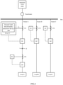
- Fig. 1 is a usage scenario diagram of a ground fault directionality detection device 100 according to an embodiment of the present disclosure.
- the scenario shown in Fig. 1 may be used as an example of a small current grounding system, and the substation supplies power to loads A, B and C such as business centers and office buildings through a transformer.
- the transformer distributes voltages to feeders A, B and C through a bus to supply power to loads A, B and C via feeders A, B and C.
- Current transformers CT1 and CT2, relays R1 and R2 are arranged on feeder A
- current transformers CT3 and relay R3 are arranged on feeder B
- current transformers CT4 and relay R4 are arranged on feeder C.
- circuit breakers Q1-Q4, loads, etc., and other unillustrated devices or apparatuses are arranged on respective feeders.
- the ground fault directivity detection device 100 may be integrated into each relay R1-R4 as a part of the relay, or into other devices located outside the relay and exchanging data or commands with the relay via a wired or wireless network, or into a fault passage indicator FPI deployed on a line.
- the ground fault directionality detection device 100 may sample a ground fault current signal I F , detect the directionality of the current signal I F , and generate a detection result, the detection result may indicate whether the current signal I F belongs to a current signal representing an upstream fault (hereinafter referred to as an upstream fault current signal) or a current signal representing a downstream fault (hereinafter referred to as a downstream fault current signal).
- the upstream fault and downstream fault are divided according to the protection range of a protection device (such as relays R1-R4 or FPI). For example, for each of relays R1-R4, faults occurring inside the protection range of itself are downstream faults, whereas faults occurring outside the protection range of itself are upstream faults.
- a fault F when a fault F occurs at a position of the feeder line A as shown in Fig. 1 , it is a downstream fault for the relay R1 and an upstream fault for the relays R2 ⁇ R4.
- ground fault directionality detection devices 100 arranged in relays R1 and R2 respectively perform directionality detection on ground fault current signals I F , and the ground fault directionality detection device 100 in relay R1 obtains a detection result indicating the fault F is a downstream fault, while the ground fault directionality detection device 100 in relay R2 obtains a detection result indicating the fault F is an upstream fault.
- the fault occurred in the protection range of relay R1.
- the ground fault directionality detection device 100 is configured with a ground fault directionality detection neural network according to an embodiment of the present disclosure.
- a ground fault directionality detection neural network With this neural network, feature extraction process may be performed on the ground fault current signal I F , and a detection result may be generated based on the extracted features, and the detection result indicates whether the ground fault belongs to an upstream fault or a downstream fault.
- the ground fault directionality detection neural network needs to be trained in advance to be a neural network capable of performing fault detection directionality detection by using a training method of the ground fault directionality detection neural network according to the embodiment of the present disclosure.
- the ground fault directionality detection device 100 may also output the detection result to a display device (not shown in this figure), which may display the detection result in a user-friendly manner such as text, numbers, and images.
- the detection result is generated by the ground fault directionality detection device 100 using the trained ground fault directionality detection neural network, with the obvious advantages of neural network in feature extraction and classification, it overcomes the shortcomings such as the need to collect voltage information, the need to put additional resistors into usage, and the low reliability of the detection result, and it realizes more efficient and accurate ground fault directionality detection.
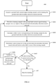
- Fig. 2 is a flowchart of a ground fault directivity detection method 200 according to an embodiment of the present disclosure.
- the ground fault directionality detection method 200 shown in Fig. 2 may be implemented by the ground fault directionality detection device 100 in Fig. 1 in which a ground fault directionality detection neural network trained according to a training method of the embodiment of the present disclosure is configured. As shown in Fig. 2 , the ground fault directivity detection method 100 may include steps S201-S205.
- a current signal I is sampled to obtain a numerical matrix M.
- the current signal I in this step may also be a current signal after proper preprocessing, the proper preprocessing includes but is not limited to converting a ground fault current signal with a larger value into a current signal with a smaller value according to a certain ratio via a current transformer.
- the numerical matrix M in this step is an arrangement of the sampled values of the ground fault current signal I, in which one row or one column corresponds to one phase of the current signal. For example, when the ground fault current signal I is a three-phase current, sampling N cycles will result in a numerical matrix M with a size of 3 ⁇ Nk, and one row of the numerical matrix M corresponds to one phase of the three-phase current signal.
- the numerical matrix M is provided as an input to a ground fault directionality detection neural network.
- the ground fault directionality detection neural network is a trained neural network, and the training method for it will be described below with reference to Figure 4 .
- a label vector V corresponding to the numerical matrix M is calculated by the ground fault directionality detection neural network, and the label vector V indicates whether the current signal I is an upstream fault current signal or a downstream fault current signal.
- the ground fault directionality detection neural network performs feature extraction processing on the current signal I, and generates a detection result based on the extracted features.
- the ground fault directionality detection neural network performs a series of operations on the numerical matrix M input in step S203 to obtain a label vector V indicating whether the ground fault is an upstream fault or a downstream fault.
- a category corresponding to a maximum value in the label vector V is considered as a prediction result of the ground fault directionality detection neural network.
- steps S201 ⁇ S203 are performed on the assumption that the current signal I is a ground fault current signal. That is, if the current signal I is determined to be a ground fault current signal, the label vector V calculated in step S203 is valid, and if the current signal I is not determined to be a ground fault current signal, the label vector V calculated in step S203 is invalid. Therefore, in steps S204 and S205, it is further determined whether the label vector V should be output in combination with a ground fault confirmation signal. The reason for doing this is that in the small current grounding system, the capture opportunity of the ground fault current signal is very short, and it can only be captured during the fault transient with a short duration.
- steps S201 ⁇ S203 are performed after the current signal is determined as the ground fault current signal, the capture opportunity of the ground fault current signal may be missed.
- the generation process of the ground fault confirmation signal mentioned in the following steps S204 and S205 is synchronized with steps S201 ⁇ S203.
- a ground fault confirmation signal is received by the ground fault directionality detection neural network.
- the ground fault confirmation signal may be a signal from other devices, apparatuses, or components (for example, other components in relays) calculated according to a specific algorithm, which may indicate whether the current signal in steps S201 to S203 is the ground fault current signal.
- a variety of principles well known to those skilled in the art may be used to determine whether the current signal is the ground fault current signal.
- a current signal is considered as a ground fault current signal when it is monitored that a residual voltage signal continuously exceeds a threshold value for a period of time (in the case of no additional voltage sensor), such as 500 ms, or when it is monitored that the Fourier value of the residual current is continuously greater than or equal to 3 amps than the value before the fault. Since determining whether the current signal is a ground fault current signal is not the subject of this disclosure, it will not be described in detail to avoid obscuring this disclosure.
- step S205 when the ground fault confirmation signal indicates that the current signal I is a ground fault current signal, the label vector V is output by the ground fault directionality detection neural network.
- the label vector V calculated in step S203 is considered as valid, and the label vector V is output.
- the label vector V calculated in step S203 is considered as invalid, and the label vector V is not output.
- the ground fault directionality detection neural network is used to judge whether the ground fault is an upstream fault or a downstream fault. Since it only needs to analyze the current signal without collecting voltage information, and the current transformer and relay in the line may collect the current signal, the ground fault detection method according to the embodiment of this disclosure may be implemented conveniently without considering the deployment of additional voltage sensors, which saves costs and makes fault directionality detection easier to perform. In addition, since the neural network has obvious advantages in feature extraction and feature-based classification, this method also improves the accuracy of directionality detection of the ground fault.
- Fig. 3 is a flowchart of a ground fault directivity detection method 300 according to another embodiment of the present disclosure.
- an enabling threshold may be set for the ground fault directionality detection neural network.
- the ground fault directivity detection method 300 may include steps S301-S306.
- Step S301 in method 300 is the same as step S201 in Fig. 2 , except that a judgment operation on a preset enabling threshold at step 302 is added.
- a maximum value in the numerical matrix M obtained at step S301 is greater than a preset enabling threshold, and the maximum value corresponds to the maximum current value in the sampled current signal I.
- the meaning of this equation is that a semaphore X k-2n in normal load state before the fault can be subtracted from a semaphore x k collected just after the fault occurs, and a semaphore before two sampling cycles may be taken as a reference quantity in a normal load state.
- the preset enabling threshold Tenable may be changed manually, for example, according to a power environment within a protection range of the relay.
- step S302 determines whether the maximum value in the numerical matrix M is greater than or equal to the preset enabling threshold Tenable. If the judgment result of step S302 is that the maximum value in the numerical matrix M is greater than or equal to the preset enabling threshold Tenable, method 300 proceeds to step S303. Similar to step S202 of method 200, in step S303, the numerical matrix M is provided as an input to the ground fault directionality detection neural network. Similar to step S203 of method 200, in step S304, a label vector V corresponding to the numerical matrix M is calculated by the ground fault directionality detection neural network, the label vector V indicates whether the current signal I is an upstream fault current or a downstream fault current. If the judgment result in step S302 is that the maximum value in the numerical matrix M is smaller than the preset enabling threshold Tenable, wait for the next numerical matrix M obtained in step S301. It should be understood that step S301 in Fig. 3 may be continuously performed, that is, the current signal I may be continuously sampled (for example, the sampling range for each sample is one cycle of
- Steps S305 and S306 are the same as steps S204 and S205 in Fig. 2 , respectively, and will not be repeatedly described here.
- the ground fault directionality detection neural network is enabled only after the preset enabling threshold is met, thus saving computing resources.
- Fig. 4 is a flowchart of a training method 400 of a ground fault directionality detection neural network according to an embodiment of the present disclosure.
- the training method 400 of the ground fault directionality detection neural network includes steps S401 ⁇ S407.
- each sample in the ground fault current signal training sample set may be a ground fault current signal collected in an actual ground fault occurrence scenario or a ground fault current signal generated by an electromagnetic transient simulation program EMTP or other software programs according to a specific algorithm, and these ground fault current signals may include a current signal representing upstream fault and a current signal representing downstream fault.
- the training samples generated by EMTP may be used as a supplement.
- the goal of training the ground fault directionality detection neural network is to minimize the difference between the label vector calculated by the ground fault directionality detection neural network and the real label vector for each sample in the training sample set of the ground fault current signal.
- the training sample in the current signal training sample set is provided as the input to the ground fault directionality detection neural network.
- the training sample input in this step may be all samples, some samples or one sample of the training sample set depending on a sample size of the sample set, size of computing resources, requirements of network prediction accuracy, and so on.
- a label vector corresponding to the training sample is calculated by the ground fault directionality detection neural network.
- the ground fault directionality detection neural network performs feature extraction on the training sample input in step S402, and classifies it according to the extracted features to obtain the label vector V indicating whether the current signal corresponding to the training sample is an upstream fault current signal or a downstream fault current signal.
- a processing loss of the ground fault directionality detection neural network is determined based on the label vector of the training sample.
- the label vector output by the ground fault directionality detection neural network may be compared with the known real label vector. For example, it is known that, for a training sample which is actually a upstream fault, the real label vector is [1,0], indicating that the probability of the training sample being an upstream fault current signal is 1, and the probability of the training sample being a downstream fault current signal is 0; for a training sample which is actually a downstream fault, its real label vector is [0,1], indicating that that the probability of the training sample being an upstream fault current signal is 0, and the probability of the training sample being a downstream fault current signal is 1.
- the output label vector of the training sample may be quite different from the real label vector of the training sample.
- the output label vector may be [0.2,0.8], indicating that the neural network considers that the sample is an upstream fault current signal with a probability of 0.2 and the sample is a downstream fault current signal with a probability of 0.8.
- the calculated label vector is [0.7,0.3], indicating that the neural network considers that the sample is a downstream fault current signal with the probability of 0.7 and the sample is an upstream fault current signal with a probability of 0.3.
- the difference between the label vector output by the ground fault detection neural network and the real label vector may be measured by the processing loss L.
- the determination of processing loss L is related to a loss function selected for the ground fault directionality detection neural network.
- the loss function may be one of the mean square error function, cross-entropy loss function, L1 loss function, L2 loss function, and the like.
- the processing loss L may be determined according to Batch Gradient Descent (BGD), Mini-Batch Gradient Descent (SGD) or Stochastic Gradient Descent (MBGD).
- step S405 it is judged whether the processing loss L is greater than or equal to a preset processing loss threshold T L .
- the preset processing loss threshold T L may be selected in combination with the prediction accuracy of the ground fault directionality detection neural network based on the protection range of the ground fault directionality detection device, for example, 0.01 and 0.02 may be selected. If it is judged that the processing loss L is greater than or equal to the preset processing loss threshold T L , it is considered that the training of the ground fault directionality detection neural network has not been completed, and the process proceeds to step S406. On the contrary, if it is judged that the processing loss L is less than the preset processing loss threshold T L , it is considered that the training of the ground fault directionality detection neural network has been completed, and the process proceeds to step S407.
- a parameter of the ground fault directionality detection neural network are updated.
- the back propagation algorithm may be used to update one or more parameters in the ground fault directionality detection neural network, these parameters mainly include weight parameters of each layer of the neural network, for example, a weight matrix of one or more convolution kernels in a convolution layer, a weight matrix of a first and/or second fully connected layer, etc.
- steps S402 to S405 are repeated until it is judged in step S405 that the processing loss L is less than the preset processing loss threshold T L , and then in step S407, the training of the ground fault directionality detection neural network is stopped.
- Fig. 5 is a structural schematic diagram of a ground fault directionality detection neural network according to an embodiment of the present disclosure.
- the ground fault directionality detection neural network may be a convolutional neural network including a convolution layer, a first fully connected layer, a second fully connected layer, an activation layer and an output layer.
- the convolution layer may include n convolution kernels: convolution kernel 1, convolution kernel 2, ..., and convolution kernel n.
- a numerical matrix input to the directionality detection neural network of ground fault is M.
- the numerical matrix M After the numerical matrix M is input into the directionality detection neural network of a ground fault, it is first processed by the convolution layer.
- Each of the convolution kernels 1 to n included in the convolution layer is convoluted with the numerical matrix M to obtain a convolution result of the first convolution layer, that is, the numerical matrix C.
- One row in the numerical matrix C corresponds to a convolution result of one of the convolution kernels 1 to n and the numerical matrix M.
- the numerical matrix C is expanded into one row or one column, and the expanded result is the first fully connected layer, which is denoted as the numerical matrix U 1 .
- the numerical matrix U 1 is multiplied by a weight matrix W 1 of the first fully connected layer to obtain a second fully connected layer, which is denoted as the numerical matrix U 2 .
- the numerical matrix U 2 is multiplied by a weight matrix W 2 of the second fully connected layer to obtain a weighted sum vector S.
- the weighted sum vector S is transformed into the label vector V by using an activation function G(z) of the activation layer.
- the label vector V may indicate whether the detected current signal is an upstream fault current signal or a downstream fault current signal.
- the activation function G(z) of the activation layer may include but is not limited to one of sigmoid function, relu function and tanh function.
- a pooling layer may be included after the convolution layer, and the pooling layer may adopt an average pooling method or a maximum pooling method to reduce the dimension of the result numerical matrix C of the convolution layer; for another example, a number of convolution layers, pooling layers, fully connected layers, active layers, etc., may be modified according to the training situation of the ground fault directionality detection neural network, for example, when the training process is over-fitted, the structure of the ground fault directionality detection neural network may be simplified, such as reducing convolution layers; for example, the number and size of convolution kernels included in each convolution layer may be modified, and the size of convolution kernel included in respective convolution layers may be different.
- Such changes or modifications can not be exhaustive herein.
- the size of convolution kernels 1 and 2 is 5 ⁇ 5
- the processing loss threshold T L is set to 0.01
- the activation function ⁇ (z) 1/(1 + e - z ) is used for the activation layer.
- EMTP is used to generate 4000 numerical matrices representing sampled ground fault current signals as a training sample set
- the training sample set includes 2000 numerical matrices corresponding to upstream fault current signals and 2000 numerical matrices corresponding to downstream fault current signals.
- These 4000 numerical matrices are randomly sorted and given the numbers M 1 ⁇ M 4000 in sequence.
- For the upstream fault current signal sample its real label vector is [1,0], indicating that the probability of the sample being an upstream fault current signal is 1, and the probability of the sample being a downstream fault current signal is 0.
- the downstream fault current signal sample its real label vector should be [0,1], indicating that the probability of the sample being an upstream fault current signal is 0, and the probability of the sample being a downstream fault current signal is 1.
- the training sample M 1 is provided to the ground fault directionality detection neural network.
- M 1 is known as the upstream fault current signal sample, and real label vector of it is [1,0].
- the label vector y 1 corresponding to M 1 is output by the ground fault directionality detection neural network, for example, [0.4, 0.6], that is to say, at this time, the ground fault directionality detection neural network considers that the probability of the sample M 1 being an upstream fault current signal is 0.4, and the probability of being a downstream fault current signal is 0.6, which shows that the classification of the sample M 1 by the ground fault directionality detection neural network is completely wrong at this time.
- the ground fault directionality detection neural network updates its parameters according to the back propagation algorithm, and these parameters include a weight matrix of convolution kernels 1 and 2 of the convolution layer with a size of 5 ⁇ 5, a weight matrix W 1 of the first fully connected layer with a size of 20 ⁇ 44 and a weight matrix W 2 of the second fully connected layer with a size of 2 ⁇ 20.
- step S402 ⁇ S406 are repeated, that is, the training sample M 2 is provided to the ground fault directionality detection neural network, and then a feature extraction, classification, processing loss calculation, and the like are performed for the training sample M 2 .
- step S407 is executed, that is, the training ends.
- the determined 2 ⁇ 5 ⁇ 5 weight matrix corresponding to two convolution kernels After training, the determined 20 ⁇ 44 weight matrix corresponding to the weight matrix W 1 of the first fully connected layer and the determined 2 ⁇ 20 weight matrix corresponding to the weight matrix W 2 of the second fully connected layer will be obtained.
- These parameters together with the structure, loss function and activation function of the previously set ground fault directionality detection neural network constitute a trained ground fault directionality detection neural network.
- step S404 is an average value of the processing losses of these samples.
- Such changes or modifications can not be exhaustive herein.
- the convolution result of each convolution kernel with the numerical matrix M is a numerical vector including 22 values, thus the convolution result of the two convolution kernels with the numerical matrix M is a numerical matrix C with a size of 2 ⁇ 22.
- the numerical matrix C is expanded into one row or one column of the first fully connected layer.
- a numerical matrix U 1 with a size of 44 ⁇ 1 is obtained by expanding the numerical matrix C into one column.
- the numerical matrix U 1 is multiplied by a weight matrix W 1 with a size of 20 ⁇ 44 of the first fully connected layer to obtain a numerical matrix U 2 with a size of 20 ⁇ 1 as the second fully connected layer.
- the numerical matrix U 2 is multiplied by a weight matrix W 2 of the second fully connected layer with a size of 2 ⁇ 20 to obtain the weighted sum vector S.
- the weighted sum vector S is transformed into a label vector V by using the activation function G(z) of the activation layer.
- the activation function G(z) of the activation layer may include but is not limited to one of sigmoid function, relu function and tanh function.
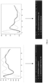
- Fig. 6 shows a test result obtained by testing the ground fault directionality detection neural network according to an embodiment of the present disclosure.
- a ground fault current signal sample belonging to a downstream fault in the test sample set is shown, where the abscissa represents indexes of the sampling points, and the ordinate of which represents the value of current with the unit of ampere (A).
- the numerical matrix is input into the ground fault directionality detection neural network, and the label vector calculated by the ground fault directionality detection neural network is [1.5835431468075839e -06 , 0.99998671408647], and the maximum value of 0.99998671408647 in the label vector represents a classification of a downstream fault, so the ground fault directionality detection neural network predicts this sample as a downstream fault current signal.
- the ground fault directionality detection neural network predicts this sample as a downstream fault current signal.
- FIG. 6 an example of a ground fault current signal sample belonging to an upstream fault in the test sample set is shown, where the abscissa represents indexes of the sampling points, and the ordinate of which represents the value of current with the unit of ampere (A).
- the numerical matrix is input into the ground fault directionality detection neural network, and the label vector calculated by the ground fault directionality detection neural network is [0.999976969348218, 3.20664547510186e -06 ], as shown in the figure.
- the maximum value of 0.999976969348218 in the label vector V represents a classification of upstream fault, so the ground fault directionality detection neural network predicts this sample as an upstream fault current signal.
- test sample set may be determined according to actual needs, for example, it may be a proportion of the sample size of the training sample set, such as 20%, 30%, etc.
- the test of the above exemplary convolutional neural network shows that the directionality detection method of ground fault according to the embodiment of the present disclosure may realize the directionality detection of ground fault only by performing feature extraction on the ground fault current signal.
- the ground fault directionality detection method disclosed in this disclosure is not limited to the above-mentioned exemplary convolutional neural network, and other suitable neural networks may also be used.
- Fig. 7 is a module block diagram showing a ground fault directivity detection device 700 according to an embodiment of the present disclosure.
- a ground fault directionality detection device 700 includes a sampling module 701, an input module 702, and a classification module 703. These three modules may be configured at the same physical location, for example, they are all integrated into the relays R1-R4 shown in Fig. 1 , and they may also be integrated into other devices with computing capability on a line, for example, the fault passage indicator FPI. Alternatively, one or two of the three modules may be configured not in the same physical location as the other two or one, and connected via a wired or wireless communication network, so as to transmit data or commands between each other.
- the sampling module 701 may be integrated into relays R1-R4 or fault passage indicator FPI, while the input module 702 and classification module 703 may be integrated into computing devices such as computers and servers in control rooms. Since a power device is allowed to run with faults for a period of time in a small current grounding system, the time spent on data and command transmission between the sampling module 701 and the input module 702 and/or the classification module 703 may not be considered.
- the input module 702 provides the numerical matrix M acquired by the sampling module 701 as an input to a ground fault directionality detection neural network. Furthermore, the input module 702 may also detect whether the maximum value in the numerical matrix M is greater than the preset enabling threshold, and provide the numerical matrix M as an input to the ground fault directivity detection neural network only when a maximum value is greater than or equal to a preset enabling threshold.
- the ground fault directionality detection neural network also receives a ground fault confirmation signal and outputs the label vector V if the ground fault confirmation signal indicates that the current signal is a ground fault current signal.
- ground fault directivity detection method is equally applicable to the ground fault directivity detection device 700, and will not be repeatedly described here.
- Fig. 8 is a hardware block diagram showing a ground fault directivity detection device 800 according to another embodiment of the present disclosure.
- An electronic device 800 includes at least a memory for storing computer program instructions and a processor for executing the computer program instructions.
- the processor executes the training method of the ground fault directionality detection neural network and the ground fault detection method.
- the ground fault directivity detection device 800 shown in Fig. 8 may specifically include a central processing unit (CPU) 801, a graphics processing unit (GPU) 802 and a main memory 803. These units are interconnected by bus 804.
- the central processing unit (CPU) 801 and/or the graphics processing unit (GPU)802 may be used as the processor, and the main memory 803 may be used as the memory for storing computer program instructions.
- the electronic device 800 may further include a communication unit 805, a storage unit 806, an output unit 808, an input unit 808 and an external device 809, which are also connected to the bus 804.
- Fig. 9 is a schematic diagram illustrating a computer-readable storage medium according to an embodiment of the present disclosure.
- a computer-readable storage medium 900 according to an embodiment of the present disclosure has computer program instructions 901 stored thereon.
- the computer program instructions 901 are executed by a processor, the training method of the ground fault directivity detection neural network and the ground fault directivity detection method according to the embodiments of the present disclosure described with reference to the above drawings are carried out.
- the computer-readable storage medium includes, but is not limited to, volatile memory and/or nonvolatile memory, for example.
- the volatile memory may include random access memory (RAM) and/or cache, for example.
- the nonvolatile memory may include, for example, a read-only memory (ROM), a hard disk, a flash memory, an optical disk, a magnetic disk, and the like.
- the directionality detection method, the directionality detection device and the computer-readable storage medium based on the neural network may accurately judge that whether a ground fault is an upstream fault or a downstream fault without voltage information.
- the test results may help locate a source of a ground fault, so as to inform a corresponding maintenance team to carry out maintenance.
- each component or step may be decomposed and/or recombined. These decompositions and/or recombinations should be regarded as equivalents of the present disclosure.
- compositions means, methods or actions of processes, machines, manufactures, events described above.
- composition, means, methods or actions of processes, machines, manufactures, events which currently exist or are to be developed later, that perform substantially the same functions or achieve substantially the same results as the corresponding aspects described herein may be utilized. Therefore, the appended claims include composition, means, methods or actions of such processes, machines, manufactures, events within their scope.
Landscapes
- Engineering & Computer Science (AREA)
- Physics & Mathematics (AREA)
- Theoretical Computer Science (AREA)
- General Physics & Mathematics (AREA)
- Mathematical Physics (AREA)
- Artificial Intelligence (AREA)
- Evolutionary Computation (AREA)
- Data Mining & Analysis (AREA)
- Computational Linguistics (AREA)
- Biophysics (AREA)
- General Health & Medical Sciences (AREA)
- Molecular Biology (AREA)
- Computing Systems (AREA)
- General Engineering & Computer Science (AREA)
- Biomedical Technology (AREA)
- Life Sciences & Earth Sciences (AREA)
- Software Systems (AREA)
- Health & Medical Sciences (AREA)
- Testing Of Short-Circuits, Discontinuities, Leakage, Or Incorrect Line Connections (AREA)
Applications Claiming Priority (1)
| Application Number | Priority Date | Filing Date | Title |
|---|---|---|---|
| CN202010794832.0A CN114076902B (zh) | 2020-08-10 | 2020-08-10 | 接地故障方向性检测方法、设备及计算机可读存储介质 |
Publications (1)
| Publication Number | Publication Date |
|---|---|
| EP3955405A1 true EP3955405A1 (fr) | 2022-02-16 |
Family
ID=77465946
Family Applications (1)
| Application Number | Title | Priority Date | Filing Date |
|---|---|---|---|
| EP21306105.4A Pending EP3955405A1 (fr) | 2020-08-10 | 2021-08-09 | Procédé de détection de défaut de directionnalité de mise a la terre, dispositif et support d'enregistrement lisible par ordinateur |
Country Status (3)
| Country | Link |
|---|---|
| US (1) | US11874317B2 (fr) |
| EP (1) | EP3955405A1 (fr) |
| CN (1) | CN114076902B (fr) |
Families Citing this family (11)
| Publication number | Priority date | Publication date | Assignee | Title |
|---|---|---|---|---|
| CN114781426A (zh) * | 2022-03-01 | 2022-07-22 | 贵州电网有限责任公司 | 一种基于深度卷积神经网络的配电网小电流接地故障成因智能辨识方法及系统 |
| CN114660502B (zh) * | 2022-03-21 | 2025-07-01 | 北京送变电有限公司 | 基于空间信息熵的谐振接地系统单相接地故障选线方法 |
| CN114779014B (zh) * | 2022-04-30 | 2025-04-11 | 长沙理工大学 | 一种灵活接地系统故障选线方法及系统 |
| CN115754588B (zh) * | 2022-11-07 | 2023-12-29 | 国网江苏省电力有限公司南通市海门区供电分公司 | 一种节约通道资源的输电线路行波测距方法 |
| CN116910622A (zh) * | 2023-07-21 | 2023-10-20 | 哈尔滨工业大学 | 用于电机的工作状态检测方法、计算设备及存储介质 |
| CN117368648B (zh) * | 2023-11-08 | 2024-06-04 | 国网四川省电力公司电力科学研究院 | 配电网单相接地故障检测方法、系统、设备和存储介质 |
| CN118937889B (zh) * | 2024-07-18 | 2025-05-09 | 国网吉林省电力有限公司白山供电公司 | 基于暂态零序电流模糊熵波形相似度的小电流接地系统故障区段定位方法 |
| CN119691546B (zh) * | 2024-11-29 | 2025-11-28 | 山东美蓝环保科技有限公司 | 一种监测过滤器失效故障点的分析判断方法、设备介质 |
| CN119535066B (zh) * | 2024-12-24 | 2026-03-10 | 广东电网有限责任公司广州供电局 | 一种高压并联电缆线路故障状态在线监测方法和系统 |
| CN120177932B (zh) * | 2025-03-03 | 2025-10-28 | 浙江大学海南研究院 | 一种基于时间约束和改进Time-ConvNeXt网络的电网故障诊断方法 |
| CN120490737B (zh) * | 2025-07-09 | 2025-11-11 | 华中科技大学 | 一种半波重构与极性增强的串联电弧故障检测方法与系统 |
Citations (2)
| Publication number | Priority date | Publication date | Assignee | Title |
|---|---|---|---|---|
| EP1890165A2 (fr) * | 2006-06-23 | 2008-02-20 | Schneider Electric Industries Sas | Procédé de détection directionnel d'un défaut à la terre et dispositif pour sa mise en oeuvre |
| FR2936319A1 (fr) * | 2008-09-25 | 2010-03-26 | Schneider Electric Ind Sas | Detection directionnelle d'un defaut a la terre par correlation lineaire |
Family Cites Families (7)
| Publication number | Priority date | Publication date | Assignee | Title |
|---|---|---|---|---|
| EP2169799B1 (fr) * | 2008-09-25 | 2019-09-04 | Schneider Electric Industries SAS | Détection directionnelle d'un défaut à la terre |
| CN103226175A (zh) * | 2013-03-21 | 2013-07-31 | 江苏省电力公司泰州供电公司 | 一种利用接地电阻阻性特征实现双端测距的方法 |
| WO2015118163A1 (fr) * | 2014-02-10 | 2015-08-13 | Katholieke Universiteit Leuven | Détection de direction d'un défaut de mise à la terre dans un réseau à phases multiples |
| US10794945B2 (en) * | 2015-09-09 | 2020-10-06 | Beijing Inhand Networks Technology Co., Ltd. | Method for detecting and locating single-phase ground fault on low current grounded power-distribution network |
| EP3460494B1 (fr) * | 2017-09-26 | 2023-01-25 | Siemens Aktiengesellschaft | Procédé et appareil de détection automatique d'un type de défaut |
| CN108279364B (zh) * | 2018-01-30 | 2020-01-14 | 福州大学 | 基于卷积神经网络的配电网单相接地故障选线方法 |
| CN110398663B (zh) * | 2019-07-03 | 2021-03-23 | 东南大学 | 一种基于卷积神经网络的柔性直流电网故障识别方法 |
-
2020
- 2020-08-10 CN CN202010794832.0A patent/CN114076902B/zh active Active
-
2021
- 2021-08-09 EP EP21306105.4A patent/EP3955405A1/fr active Pending
- 2021-08-09 US US17/397,265 patent/US11874317B2/en active Active
Patent Citations (2)
| Publication number | Priority date | Publication date | Assignee | Title |
|---|---|---|---|---|
| EP1890165A2 (fr) * | 2006-06-23 | 2008-02-20 | Schneider Electric Industries Sas | Procédé de détection directionnel d'un défaut à la terre et dispositif pour sa mise en oeuvre |
| FR2936319A1 (fr) * | 2008-09-25 | 2010-03-26 | Schneider Electric Ind Sas | Detection directionnelle d'un defaut a la terre par correlation lineaire |
Non-Patent Citations (2)
| Title |
|---|
| MORALES J ET AL: "High-speed directional protection without voltage sensors for distribution feeders with distributed generation integration based on the correlation of signals and machine learning", ELECTRIC POWER SYSTEMS RESEARCH, ELSEVIER, AMSTERDAM, NL, vol. 184, 12 March 2020 (2020-03-12), XP086135177, ISSN: 0378-7796, [retrieved on 20200312], DOI: 10.1016/J.EPSR.2020.106295 * |
| YANG QINGQING ET AL: "Artificial Neural Network Based Fault Detection and Fault Location in the DC Microgrid", ENERGY PROCEDIA, ELSEVIER, NL, vol. 103, 27 December 2016 (2016-12-27), pages 129 - 134, XP029866164, ISSN: 1876-6102, DOI: 10.1016/J.EGYPRO.2016.11.261 * |
Also Published As
| Publication number | Publication date |
|---|---|
| US20220043046A1 (en) | 2022-02-10 |
| CN114076902A (zh) | 2022-02-22 |
| CN114076902B (zh) | 2026-03-03 |
| US11874317B2 (en) | 2024-01-16 |
Similar Documents
| Publication | Publication Date | Title |
|---|---|---|
| US11874317B2 (en) | Ground fault directionality detection method, device and computer readable storage medium | |
| US11841384B2 (en) | Inrush current detection method, device and computer-readable storage medium for transformer | |
| Resmi et al. | Detection, classification and zone location of fault in transmission line using artificial neural network | |
| Shukla et al. | DC offset estimation‐based fault detection in transmission line during power swing using ensemble of decision tree | |
| Koley et al. | Protection scheme for power transmission lines based on SVM and ANN considering the presence of non‐linear loads | |
| EP3723218B1 (fr) | Procédé et dispositif de traitement d'arc de courant continu | |
| CN111366815B (zh) | 基于配电站服务器的小电流接地选线方法、装置及介质 | |
| Mousavi et al. | Artificial neural networks-based fault localization in distributed generation integrated networks considering fault impedance | |
| Ashok et al. | Fault diagnosis scheme for cross-country faults in dual-circuit line with emphasis on high-impedance fault syndrome | |
| CN113902946A (zh) | 电力系统故障方位判别方法、装置、终端设备及存储介质 | |
| Shukla et al. | Grey wolf optimization-tuned convolutional neural network for transmission line protection with immunity against symmetrical and asymmetrical power swing | |
| Dubey et al. | An spatiotemporal information system based wide-area protection fault identification scheme | |
| CN117272143B (zh) | 基于格拉姆角场与残差网络的输电线故障辨识方法和装置 | |
| Radhakrishnan et al. | Synchrophasor based islanding detection for microgrids using moving window principal component analysis and extended mathematical morphology | |
| WO2018227466A1 (fr) | Procédé de détection de défaut dans une ligne de transmission de puissance et système de protection l'utilisant | |
| CN115856504A (zh) | 一种串联电弧故障的检测方法和系统 | |
| Patel | Superimposed components of Lissajous pattern based feature extraction for classification and localization of transmission line faults | |
| Velpula et al. | Detection and Classification of EHV Transmission Line Faults Based on Sign of Reactive Power | |
| JP4110747B2 (ja) | 電力系統における高調波監視システム | |
| CN109587145B (zh) | 一种电力网络中的虚假数据入侵检测方法、装置及设备 | |
| CN111337792A (zh) | 基于改进型Petri网的电力系统故障诊断方法 | |
| Kezunovic | Translational knowledge: from collecting data to making decisions in a smart grid | |
| CN119813121A (zh) | 基于能量衰减特性的无边界柔直系统方向保护 | |
| CN119355466A (zh) | 基于时频域扰动的小电流电弧故障检测方法及相关设备 | |
| CN118150942A (zh) | 一种配电网电流接地故障定位方法、装置、设备及介质 |
Legal Events
| Date | Code | Title | Description |
|---|---|---|---|
| PUAI | Public reference made under article 153(3) epc to a published international application that has entered the european phase |
Free format text: ORIGINAL CODE: 0009012 |
|
| STAA | Information on the status of an ep patent application or granted ep patent |
Free format text: STATUS: THE APPLICATION HAS BEEN PUBLISHED |
|
| AK | Designated contracting states |
Kind code of ref document: A1 Designated state(s): AL AT BE BG CH CY CZ DE DK EE ES FI FR GB GR HR HU IE IS IT LI LT LU LV MC MK MT NL NO PL PT RO RS SE SI SK SM TR |
|
| STAA | Information on the status of an ep patent application or granted ep patent |
Free format text: STATUS: REQUEST FOR EXAMINATION WAS MADE |
|
| 17P | Request for examination filed |
Effective date: 20220816 |
|
| RBV | Designated contracting states (corrected) |
Designated state(s): AL AT BE BG CH CY CZ DE DK EE ES FI FR GB GR HR HU IE IS IT LI LT LU LV MC MK MT NL NO PL PT RO RS SE SI SK SM TR |