EP3955473B1 - Procédé de transmission et de réception d'informations d'état de canal dans un système de communication sans fil et appareil associé - Google Patents
Procédé de transmission et de réception d'informations d'état de canal dans un système de communication sans fil et appareil associé Download PDFInfo
- Publication number
- EP3955473B1 EP3955473B1 EP21193347.8A EP21193347A EP3955473B1 EP 3955473 B1 EP3955473 B1 EP 3955473B1 EP 21193347 A EP21193347 A EP 21193347A EP 3955473 B1 EP3955473 B1 EP 3955473B1
- Authority
- EP
- European Patent Office
- Prior art keywords
- instance
- csi
- cqi
- information
- case
- Prior art date
- Legal status (The legal status is an assumption and is not a legal conclusion. Google has not performed a legal analysis and makes no representation as to the accuracy of the status listed.)
- Active
Links
Images






Classifications
-
- H—ELECTRICITY
- H04—ELECTRIC COMMUNICATION TECHNIQUE
- H04B—TRANSMISSION
- H04B7/00—Radio transmission systems, i.e. using radiation field
- H04B7/02—Diversity systems; Multi-antenna system, i.e. transmission or reception using multiple antennas
- H04B7/04—Diversity systems; Multi-antenna system, i.e. transmission or reception using multiple antennas using two or more spaced independent antennas
- H04B7/0413—MIMO systems
- H04B7/0417—Feedback systems
-
- H—ELECTRICITY
- H04—ELECTRIC COMMUNICATION TECHNIQUE
- H04B—TRANSMISSION
- H04B7/00—Radio transmission systems, i.e. using radiation field
- H04B7/02—Diversity systems; Multi-antenna system, i.e. transmission or reception using multiple antennas
- H04B7/04—Diversity systems; Multi-antenna system, i.e. transmission or reception using multiple antennas using two or more spaced independent antennas
- H04B7/0413—MIMO systems
- H04B7/0426—Power distribution
-
- H—ELECTRICITY
- H04—ELECTRIC COMMUNICATION TECHNIQUE
- H04B—TRANSMISSION
- H04B7/00—Radio transmission systems, i.e. using radiation field
- H04B7/02—Diversity systems; Multi-antenna system, i.e. transmission or reception using multiple antennas
- H04B7/04—Diversity systems; Multi-antenna system, i.e. transmission or reception using multiple antennas using two or more spaced independent antennas
- H04B7/0413—MIMO systems
- H04B7/0456—Selection of precoding matrices or codebooks, e.g. using matrices antenna weighting
-
- H—ELECTRICITY
- H04—ELECTRIC COMMUNICATION TECHNIQUE
- H04B—TRANSMISSION
- H04B7/00—Radio transmission systems, i.e. using radiation field
- H04B7/02—Diversity systems; Multi-antenna system, i.e. transmission or reception using multiple antennas
- H04B7/04—Diversity systems; Multi-antenna system, i.e. transmission or reception using multiple antennas using two or more spaced independent antennas
- H04B7/0413—MIMO systems
- H04B7/0456—Selection of precoding matrices or codebooks, e.g. using matrices antenna weighting
- H04B7/0478—Special codebook structures directed to feedback optimisation
- H04B7/0479—Special codebook structures directed to feedback optimisation for multi-dimensional arrays, e.g. horizontal or vertical pre-distortion matrix index [PMI]
-
- H—ELECTRICITY
- H04—ELECTRIC COMMUNICATION TECHNIQUE
- H04B—TRANSMISSION
- H04B7/00—Radio transmission systems, i.e. using radiation field
- H04B7/02—Diversity systems; Multi-antenna system, i.e. transmission or reception using multiple antennas
- H04B7/04—Diversity systems; Multi-antenna system, i.e. transmission or reception using multiple antennas using two or more spaced independent antennas
- H04B7/06—Diversity systems; Multi-antenna system, i.e. transmission or reception using multiple antennas using two or more spaced independent antennas at the transmitting station
- H04B7/0613—Diversity systems; Multi-antenna system, i.e. transmission or reception using multiple antennas using two or more spaced independent antennas at the transmitting station using simultaneous transmission
- H04B7/0615—Diversity systems; Multi-antenna system, i.e. transmission or reception using multiple antennas using two or more spaced independent antennas at the transmitting station using simultaneous transmission of weighted versions of same signal
- H04B7/0619—Diversity systems; Multi-antenna system, i.e. transmission or reception using multiple antennas using two or more spaced independent antennas at the transmitting station using simultaneous transmission of weighted versions of same signal using feedback from receiving side
- H04B7/0621—Feedback content
- H04B7/0626—Channel coefficients, e.g. channel state information [CSI]
-
- H—ELECTRICITY
- H04—ELECTRIC COMMUNICATION TECHNIQUE
- H04B—TRANSMISSION
- H04B7/00—Radio transmission systems, i.e. using radiation field
- H04B7/02—Diversity systems; Multi-antenna system, i.e. transmission or reception using multiple antennas
- H04B7/04—Diversity systems; Multi-antenna system, i.e. transmission or reception using multiple antennas using two or more spaced independent antennas
- H04B7/06—Diversity systems; Multi-antenna system, i.e. transmission or reception using multiple antennas using two or more spaced independent antennas at the transmitting station
- H04B7/0613—Diversity systems; Multi-antenna system, i.e. transmission or reception using multiple antennas using two or more spaced independent antennas at the transmitting station using simultaneous transmission
- H04B7/0615—Diversity systems; Multi-antenna system, i.e. transmission or reception using multiple antennas using two or more spaced independent antennas at the transmitting station using simultaneous transmission of weighted versions of same signal
- H04B7/0619—Diversity systems; Multi-antenna system, i.e. transmission or reception using multiple antennas using two or more spaced independent antennas at the transmitting station using simultaneous transmission of weighted versions of same signal using feedback from receiving side
- H04B7/0636—Feedback format
- H04B7/0639—Using selective indices, e.g. of a codebook, e.g. pre-distortion matrix index [PMI] or for beam selection
Definitions
- the present invention relates to wireless communications, and more particularly, to a method for transmitting and receiving channel state information in a wireless communication system that supports multiple antenna system (particularly, 2 dimensional active antenna system (2D AAS)) and an apparatus for supporting the same.
- 2D AAS 2 dimensional active antenna system
- An object of the present invention is to propose a method for configuring a codebook for improving multi-user (MU) performance in a wireless communication system that supports multiple antenna system.
- MU multi-user
- the performance of MU transmission can be improved in a wireless communication system that supports multiple antenna system.
- the feedback overhead of channel state information can be reduced in a wireless communication system that supports multiple antenna system.
- the channel state information can be fed back by using a PUCCH format which is previously defined, without defining a new PUCCH format.
- the device may be fixed or may have mobility and may be substituted with another term, such as User Equipment (UE), a Mobile Station (MS), a User Terminal (UT), a Mobile Subscriber Station (MSS), a Subscriber Station (SS), an Advanced Mobile Station (AMS), a Wireless Terminal (WT), a Machine-Type Communication (MTC) device, a Machine-to-Machine (M2M) device, or a Device-to-Device (D2D) device.
- UE User Equipment
- MS Mobile Station
- UT User Terminal
- MSS Mobile Subscriber Station
- SS Subscriber Station
- AMS Advanced Mobile Station
- WT Wireless Terminal
- MTC Machine-Type Communication
- M2M Machine-to-Machine
- D2D Device-to-Device
- CDMA Code Division Multiple Access
- FDMA Frequency Division Multiple Access
- TDMA Time Division Multiple Access
- OFDMA Orthogonal Frequency Division Multiple Access
- SC-FDMA Single Carrier Frequency Division Multiple Access
- NOMA Non-Orthogonal Multiple Access
- CDMA may be implemented using a radio technology, such as Universal Terrestrial Radio Access (UTRA) or CDMA2000.
- TDMA may be implemented using a radio technology, such as Global System for Mobile communications (GSM)/General Packet Radio Service (GPRS)/Enhanced Data rates for GSM Evolution (EDGE).
- GSM Global System for Mobile communications
- GPRS General Packet Radio Service
- EDGE Enhanced Data rates for GSM Evolution
- OFDMA may be implemented using a radio technology, such as Institute of Electrical and Electronics Engineers (IEEE) 802.11 (Wi-Fi), IEEE 802.16 (WiMAX), IEEE 802.20, or Evolved UTRA (E-UTRA).
- UTRA is part of a Universal Mobile Telecommunications System (UMTS).
- 3rd Generation Partnership Project (3GPP) Long Term Evolution (LTE) is part of an Evolved UMTS (E-UMTS) using evolved UMTS Terrestrial Radio Access (E-UTRA), and it adopts OFDMA in downlink and adopts SC-FDMA in uplink.
- LTE-Advanced (LTE-A) is the evolution of 3GPP LTE.
- 3GPP LTE/LTE-A is chiefly described, but the technical characteristics of the present invention are not limited thereto.
- 3GPP LTE/LTE-A support a radio frame structure type 1 which may be applicable to Frequency Division Duplex (FDD) and a radio frame structure which may be applicable to Time Division Duplex (TDD).
- FDD Frequency Division Duplex
- TDD Time Division Duplex
- One slot includes a plurality of Orthogonal Frequency Division Multiplexing (OFDM) symbols in the time domain and includes a plurality of Resource Blocks (RBs) in a frequency domain.
- OFDM symbols are used to represent one symbol period because OFDMA is used in downlink.
- An OFDM symbol may be called one SC-FDMA symbol or symbol period.
- An RB is a resource allocation unit and includes a plurality of contiguous subcarriers in one slot.
- FIG. 1(b) illustrates the frame structure type 2.
- the radio frame structure type 2 consists of 2 half frames. Each of the half frames consists of 5 subframes, a Downlink Pilot Time Slot (DwPTS), a Guard Period (GP), and an Uplink Pilot Time Slot (UpPTS). One subframe consists of 2 slots.
- the DwPTS is used for initial cell search, synchronization, or channel estimation in UE.
- the UpPTS is used for channel estimation in an eNB and to perform uplink transmission synchronization with UE.
- the guard period is an interval in which interference generated in uplink due to the multi-path delay of a downlink signal between uplink and downlink is removed.
- an uplink-downlink configuration is a rule indicating whether uplink and downlink are allocated (or reserved) to all subframes.
- Table 1 shows the uplink-downlink configuration.
- Uplink-Downlink configuration Downlink-to-Uplink Switch-point periodicity Subframe number 0 1 2 3 4 5 6 7 8 9 0 5ms D S U U U D S U U U 1 5ms D S U U D D S U U D 2 5ms D S U D D D S U D D 3 10ms D S U U U D D D D D 4 10ms D S U U D D D D D D 5 10ms D S U D D D D D D D D 5 10ms D S U D D D D D D D 6 5ms D S U U U U D S U U D S U U D
- a point of time at which a change is performed from downlink to uplink or a point of time at which a change is performed from uplink to downlink is called a switching point.
- the periodicity of the switching point means a cycle in which an uplink subframe and a downlink subframe are changed is identically repeated. Both 5 ms and 10 ms are supported in the periodicity of a switching point. If the periodicity of a switching point has a cycle of a 5 ms downlink-uplink switching point, the special subframe S is present in each half frame. If the periodicity of a switching point has a cycle of a 5 ms downlink-uplink switching point, the special subframe S is present in the first half frame only.
- 0 and 5 subframes and a DwPTS are used for only downlink transmission.
- An UpPTS and a subframe subsequent to a subframe are always used for uplink transmission.
- Such uplink-downlink configurations may be known to both an eNB and UE as system information.
- An eNB may notify UE of a change of the uplink-downlink allocation state of a radio frame by transmitting only the index of uplink-downlink configuration information to the UE whenever the uplink-downlink configuration information is changed.
- configuration information is kind of downlink control information and may be transmitted through a Physical Downlink Control Channel (PDCCH) like other scheduling information.
- Configuration information may be transmitted to all UEs within a cell through a broadcast channel as broadcasting information.
- PDCCH Physical Downlink Control Channel
- Table 2 illustrates the configuration of the special subframe (DwPTS/GP/UpPTS length).
- Special subframe configuration Normal cyclic prefix in downlink Extended cyclic prefix in downlink DwPTS UpPTS DwWPTS UpPTS Normal cyclic prefix in uplink Extended cyclic prefix in uplink Normal cyclic prefix in uplink Extended cyclic prefix in uplink 0 6592 ⁇ T s 2192 ⁇ T s 2560 ⁇ T s 7680 ⁇ T s 2192 ⁇ T s 2560 ⁇ T s 1 19760 ⁇ T s 20480 ⁇ T s 2 21952 ⁇ T s 23040 ⁇ T s 3 24144 ⁇ T s 25600 ⁇ T s 4 26336 ⁇ T s 7680 ⁇ T s 4384 ⁇ T s 5120 ⁇ T s 5 6592 ⁇ T s 4384 ⁇ T s 5120 ⁇ T s 20480 ⁇ T s 6 19760 ⁇ T s 23040 ⁇ T s 7 21
- the structure of a radio frame is only one example.
- the number of subcarriers included in a radio frame or the number of slots included in a subframe and the number of OFDM symbols included in a slot may be changed in various ways.
- FIG. 2 is a diagram illustrating a resource grid for one downlink slot in a wireless communication system to which an embodiment of the present invention may be applied.
- one downlink slot includes a plurality of OFDM symbols in a time domain. It is described herein that one downlink slot includes 7 OFDMA symbols and one resource block includes 12 subcarriers for exemplary purposes only, and the present invention is not limited thereto.
- Each element on the resource grid is referred to as a resource element, and one resource block (RB) includes 12 ⁇ 7 resource elements.
- the number of RBs N ⁇ DL included in a downlink slot depends on a downlink transmission bandwidth.
- the structure of an uplink slot may be the same as that of a downlink slot.
- FIG. 3 shows the structure of a downlink subframe in a wireless communication system to which an embodiment of the present invention may be applied.
- a maximum of three OFDM symbols located in a front portion of a first slot of a subframe correspond to a control region in which control channels are allocated, and the remaining OFDM symbols correspond to a data region in which a physical downlink shared channel (PDSCH) is allocated.
- Downlink control channels used in 3GPP LTE include, for example, a physical control format indicator channel (PCFICH), a physical downlink control channel (PDCCH), and a physical hybrid-ARQ indicator channel (PHICH).
- a PCFICH is transmitted in the first OFDM symbol of a subframe and carries information about the number of OFDM symbols (i.e., the size of a control region) which is used to transmit control channels within the subframe.
- a PHICH is a response channel for uplink and carries an acknowledgement (ACK)/not-acknowledgement (NACK) signal for a Hybrid Automatic Repeat Request (HARQ).
- Control information transmitted in a PDCCH is called Downlink Control Information (DCI).
- DCI includes uplink resource allocation information, downlink resource allocation information, or an uplink transmission (Tx) power control command for a specific UE group.
- a PDCCH may carry information about the resource allocation and transport format of a downlink shared channel (DL-SCH) (this is also called an "downlink grant”), resource allocation information about an uplink shared channel (UL-SCH) (this is also called a “uplink grant”), paging information on a PCH, system information on a DL-SCH, the resource allocation of a higher layer control message, such as a random access response transmitted on a PDSCH, a set of transmission power control commands for individual UE within specific UE group, and the activation of a Voice over Internet Protocol (VoIP), etc.
- a plurality of PDCCHs may be transmitted within the control region, and UE may monitor a plurality of PDCCHs.
- a PDCCH is transmitted on a single Control Channel Element (CCE) or an aggregation of some contiguous CCEs.
- CCE is a logical allocation unit that is used to provide a PDCCH with a coding rate according to the state of a radio channel.
- a CCE corresponds to a plurality of resource element groups.
- the format of a PDCCH and the number of available bits of a PDCCH are determined by an association relationship between the number of CCEs and a coding rate provided by CCEs.
- An eNB determines the format of a PDCCH based on DCI to be transmitted to UE and attaches a Cyclic Redundancy Check (CRC) to control information.
- CRC Cyclic Redundancy Check
- a unique identifier (a Radio Network Temporary Identifier (RNTI)) is masked to the CRC depending on the owner or use of a PDCCH. If the PDCCH is a PDCCH for specific UE, an identifier unique to the UE, for example, a Cell-RNTI (C-RNTI) may be masked to the CRC.
- RNTI Radio Network Temporary Identifier
- FIG. 4 shows the structure of an uplink subframe in a wireless communication system to which an embodiment of the present invention may be applied.
- the uplink subframe may be divided into a control region and a data region in a frequency domain.
- a physical uplink control channel (PUCCH) carrying uplink control information is allocated to the control region.
- a physical uplink shared channel (PUSCH) carrying user data is allocated to the data region.
- PUCCH physical uplink control channel
- PUSCH physical uplink shared channel
- N RB UL represents the number of resource blocks in the uplink and 0, 1, ... , N RB UL -1 mean numbers of physical resource blocks.
- the PUCCH is mapped to both edges of an uplink frequency block.
- a reporting period of the channel measurement feedback (hereinafter, collectively expressed as CQI information) and a frequency unit (or, a frequency resolution) to be a target of measurement may be controlled by an eNB.
- CQI information channel measurement feedback
- a frequency unit or, a frequency resolution
- periodic and aperiodic CQI reporting may be supported.
- PUCCH format 2 may be used for only the periodic reporting and a PUSCH may be used for aperiodic reporting.
- an eNB may instruct the terminal to transmit a scheduling resource loaded with individual CQI reporting for the uplink data transmission.
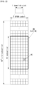
- FIG. 6 illustrates a structure of a CQI channel in the case of a normal CP in a wireless communication system to which the present invention may be applied.
- SC-FDMA symbols 0 to 6 of a single slot SC-FDMA symbols 1 and 5 (second and sixth symbols) are used for transmission of a demodulation reference signal (DMRS) and CQI information may be transmitted in the other remaining SC-FDMA symbols.
- DMRS demodulation reference signal
- SC-FDMA symbol 3 SC-FDMA symbol 3
- PUCCH formats 2/2a/2b supports modulation based on CAZAC sequence, and a QPSK-modulated symbol is multiplied to a CAZAC sequence having a length of 12.
- a CS of a sequence is changed between a symbol and a slot.
- Orthogonal covering is used for a DMRS.
- a reference signal is carried in two SC-FDMA symbols spaced apart by a three SC-FDMA symbol interval, among seven SC-FDMA symbols included in one slot, and CQI information is carried in the other remaining five SC-FDMA symbols.
- Two RSs are used in one slot to support a high speed UE.
- each UE is distinguished using a CS sequence.
- CQI information symbols are modulated in the entire SC-FDMA symbols and transferred, and the SC-FDMA symbols are configured as one sequence. That is, a UE modulates a CQI to each sequence and transmits the same.
- CQI information bits is channel-coded by (20, k) Reed-Muller (RM) code which is 1/2 rate punctured and 20 coded bits are generated.
- RM Reed-Muller
- a coded bit is scrambled before QPSK constellation mapping (which is similar to the case that PUSH data is scrambled with Gold sequence of a length of 31).
- the number of symbols that may be transmitted in one TTI is 10 symbols, and modulation of CQI information is determined to QPSK.
- a 2-bit CQI value may be carried, and thus, a 10-bit CQI value may be carried in one slot. Accordingly, a maximum of 20-bit CQI value may be carried in one subframe.
- a frequency domain spreading code is used.
- a CAZAC sequence having a length of 12 may be used as the frequency domain spreading code.
- Each control channel may be distinguished by applying CAZAC sequence having a different cyclic shift value.
- IFFT is performed on frequency domain-spread CQI information.
- 12 different UEs may be orthogonally multiplexed on the same PUCCH RB by 12 cyclic shifts which are equally spaced from each other.
- a DMRS sequence on SC-FDMA symbols 1 and 5 is similar to a CQI signal sequence on a frequency domain but the same modulation as that applied to CQI information is not applied.
- a UE may be semi-statically set by higher layer signaling to periodically report different CQI, PMI, and RI types on the PUCCH resource indicated by PUCCH resource indices ( n PUCCH 1 p ⁇ , n PUCCH 2 p ⁇ , n PUCCH 3 p ⁇ ).
- the PUCCH resource index ( n PUCCH 2 p ⁇ ) is information indicating a PUCCH region used for PUCCH format 2/2a/2b transmission and a cyclic shift (CS) value to be used.
- the CAZAC sequence having the length of 12 is multiplied by a symbol modulated by using a BPSK or QPSK modulation scheme.
- y(0), . . . , y(N-1) symbols may be designated as a block of symbols.
- the modulated symbol is multiplied by the CAZAC sequence and thereafter, the block-wise spread using the orthogonal sequence is adopted.
- a Hadamard sequence having a length of 4 is used with respect to general ACK/NACK information and a discrete Fourier transform (DFT) sequence having a length of 3 is used with respect to the ACK/NACK information and the reference signal.
- DFT discrete Fourier transform
- the Hadamard sequence having the length of 2 is used with respect to the reference signal in the case of the extended CP.
- FIG. 7 illustrates a structure of an ACK/NACK channel in the case of a normal CP in the wireless communication system to which the present invention may be applied.
- FIG. 7 a PUCCH channel structure for transmitting the HARQ ACK/NACK without the CQI is exemplarily illustrated.
- a reference signal is carried on three consecutive SC-FDMA symbols in a middle part among 7 SC-FDMA symbols and the ACK/NACK signal are carried on the remaining 4 SC-FDMA symbols.
- the RS may be carried on two consecutive symbols in the middle part.
- the number of and the positions of symbols used in the RS may vary depending on the control channel and the numbers and the positions of symbols used in the ACK/NACK signal associated with the positions of symbols used in the RS may also correspondingly vary depending on the control channel.
- Acknowledgment response information (not scrambled status) of 1 bit and 2 bits may be expressed as one HARQ ACK/NACK modulated symbol by using the BPSK and QPSK modulation techniques, respectively.
- a positive acknowledgement response (ACK) may be encoded as '1' and a negative acknowledgment response (NACK) may be encoded as '0'.
- a cyclic time shift of basic RS sequence of a length of 12 is applied before OFDM modulation (i.e., frequency domain CDM), and a single BPSK/QPSK modulation symbol is transmitted on each SC-FDMA data symbol.
- OFDM modulation i.e., frequency domain CDM
- 2-dimensional spread is adopted in order to increase a multiplexing capacity. That is, frequency domain spread and time domain spread are simultaneously adopted in order to increase the number of terminals or control channels which may be multiplexed.
- a frequency domain sequence is used as the base sequence in order to spread the ACK/NACK signal in the frequency domain.
- a Zadoff-Chu (ZC) sequence which is one of the CAZAC sequences may be used as the frequency domain sequence.
- ZC Zadoff-Chu
- CSs Cyclic Shifts
- CSs Cyclic Shifts
- the number of CS resources supported in an SC-FDMA symbol for PUCCH RBs for HARQ ACK/NACK transmission is set by a cell-specific higher-layer signaling parameter ( ⁇ shift PUCCH ).
- the ACK/NACK signal which is frequency-domain spread is spread in the time domain by using an orthogonal spreading code.
- an orthogonal spreading code a Walsh-Hadamard sequence or DFT sequence may be used.
- the ACK/NACK signal may be spread by using an orthogonal sequence (w0, w1, w2, and w3) having the length of 4 with respect to 4 symbols.
- the RS is also spread through an orthogonal sequence having the length of 3 or 2. This is referred to as orthogonal covering (OC).
- the number of spreading codes supported with respect to the ACK/NACK information is limited by the number of RS symbols. That is, since the number of RS transmitting SC-FDMA symbols is smaller than that of ACK/NACK information transmitting SC-FDMA symbols, the multiplexing capacity of the RS is smaller than that of the ACK/NACK information.
- HARQ acknowledgement responses from a total of 18 different UEs may be multiplexed in one PUCCH RB.
- ACK is encoded by binary '1' and NACK is encoded by binary '0'.
- dHARQ single HARQ ACK/NACK modulation symbol
- SC-FDMA symbol 5 the second RS symbol
- a UE selects M preferred subbands for a band (set S) designated by system bandwidth or a higher layer.
- the UE generates wideband CQI value for system bandwidth or set S additionally.
- a UE generates wideband CQI value.
- a UE generates a single precoding matrix for system bandwidth or set S.
- the UE generates wideband CQI by assuming the single precoding matrix.
- Subband CQI subband CQI index ⁇ wideband CQI index
- subband size may be changed according to a size of system bandwidth.
- PUCCH format 3 is used for ACK/NACK feedback use for DL data by a UE.
- a UE was able to transmit maximum 2 bits ACK/NACK information to an eNB through PUCCH format 1a/1b.
- CA Carrier Aggregation
- a UE should report ACK/NACK information that corresponds one UL subframe and four DL subframes.
- a UE should report ACK/NACK information that corresponds to maximum 4n DL subframes in a single UL subframe. That is, in the case of 5CC CA, a UE should report ACK/NACK information that corresponds to 20 DL subframes.
- the CSI feedback periodically transmitted in PUCCH format 2 collides with ACK/NACK information reporting of PUCCH format 3 in a UL subframe operates as follows according to current LTE-A standard.
- the spare capacity of PUCCH 3 except ACK/NACK payload (in the case that SR information is existed, payload size 1 bit of the SR information is also added and calculated) is CSI payload size or greater, the ACK/NACK and the CSI are transmitted through PUCCH 3. Otherwise, the CSI is not transmitted (i.e., CSI is dropped) but only ACK/NACK is transmitted.
- precoding feedback is used for channel dependent codebook based precoding and dependent upon UE(s) that reports PMI.
- a UE reports the PMI.
- PMI/RI reporting is configured, and when CSI-RS port is greater than 1, a UE reports the PMI.
- a UE reports the PMI based on feedback mode. In other transmission modes, the PMI reporting is not supported.
- each PMI value corresponds to codebook index represented in Table 11 below.
- Table 11 exemplifies a codebook for a transmission on antenna port ⁇ 0, 1 ⁇ and CSI reporting based on antenna port ⁇ 0, 1 ⁇ or ⁇ 15, 16 ⁇ .
- each PMI value corresponds to the codebook index provided in Table 12 below or corresponds to a pair of codebook indexes provided in Tables 13 to 16 below.
- a first PMI value i 1 ⁇ 0,1, ⁇ ,f( ⁇ )-1 ⁇ and a second PMI value i 2 ⁇ ⁇ 0,1, ⁇ , g ( ⁇ )-1 ⁇ correspond to codebook indexes i 1 and i 2 provided in Table j for associated RI value and the same ⁇ , respectively.
- ⁇ ⁇ 1,2,3,4 ⁇
- f ( ⁇ ) ⁇ 16,16,1,1 ⁇
- I is a 4 ⁇ 4 unit matrix
- vector u n is determined in Table 7.
- n i 2 .
- codebook subsampling is supported.
- Table 12 exemplifies a codebook for a transmission on antenna ports ⁇ 0, 1, 2, 3 ⁇ and CSI reporting based on antenna ports ⁇ 0, 1, 2, 3 ⁇ or ⁇ 15, 16, 17, 18 ⁇ .
- Table 13 exemplifies a codebook for 1 layer CSI reporting using antenna ports 0 to 3 or 15 to 18.
- i 1 i 2 0 1 2 3 4 5 6 7 0-15 W i 1 , 0 1 W i 1 , 8 1 W i 1 , 16 1 W i 1 , 24 1 W i 1 + 8 , 2 1 W i 1 + 8 , 10 1 W i 1 + 8 , 18 1 W i 1 + 8 , 26 1 i 1 i 2 8 9 10 11 12 13 14 15 0-15 W i 1 + 16 , 4 1 W i 1 + 16 , 12 1 W i 1 + 16 , 20 1 W i 1 + 16 , 28 1 W i 1 + 24 , 6 1 W i 1 + 24 , 14 1 W i 1 + 24 , 22 1 W i 1 + 24 , 30 1 W m , n 1 1 2 ⁇ ′ m ⁇ ′ n ⁇ ′ m
- Table 14 exemplifies a codebook for 2 layer CSI reporting using antenna ports 0 to 3 or 15 to 18.
- i 1 i 2 0 1 2 3 0-15 W i 1 , i 1 , 0 2 W i 1 , i 1 , 1 2 W i 1 + 8 , i 1 + 8 , 0 2 W i 1 + 8 , i 1 + 8 , 1 2 i 1 i 2 4 5 6 7 0-15 W i 1 + 16 , i 1 + 16 , 0 2 W i 1 + 16 , i 1 + 16 , 1 2 W i 1 + 24 , i 1 + 24 , 0 2 W i 1 + 24 , i 1 + 24 , 1 2 i 1 i 2 8 9 10 11 0-15 W i 1 , i 1 + 8 , 0 2 W i 1 , i 1 + 8 , 1 2 W i 1 + 8 , i 1 + 16 , 0 2 W i
- Table 15 exemplifies a codebook for 3-layer CSI report using antenna ports 15 to 18.
- [Table 15] i 1 i 2 0 1 2 3 4 5 6 7 0 W 0 124 / 3 W 1 123 / 3 W 2 123 / 3 W 3 123 / 3 W 4 124 / 3 W 5 124 / 3 W 6 134 / 3 W 7 134 / 3 i 1 i 2 8 9 10 11 12 13 14 15 0 W 8 124 / 3 W 9 134 / 3 W 10 123 / 3 W 11 134 / 3 W 12 123 / 3 W 13 123 / 3 W 14 123 / 3 W 15 123 / 3
- Table 16 exemplifies a codebook for 4-layer CSI report using antenna ports 15 to 18.
- [Table 16] i 1 i 2 0 1 2 3 4 5 6 7 0 W 0 1234 / 2 W 1 1234 / 2 W 2 3214 / 2 W 3 3214 / 2 W 4 1234 / 2 W 5 1234 / 2 W 6 1324 / 2 W 7 1324 / 2 i 1 i 2 8 9 10 11 12 13 14 15 0 W 8 1234 / 2 W 9 1234 / 2 W 10 1324 / 2 W 11 1324 / 2 W 12 1234 / 2 W 13 1324 / 2 W 14 3214 / 2 W 15 1234 / 2
- each PMI value corresponds to a pair of codebook indexes given by Table 17 to Table 24 below.
- ⁇ n and v m are as represented in Equation 8 below.
- ⁇ n e j ⁇ n / 2
- ⁇ m 1 e j 2 ⁇ m / 32 e j 4 ⁇ m / 32 e j 6 ⁇ m / 32 T
- a first PMI value ( i 1 ⁇ ⁇ 0,1, ⁇ , f ( ⁇ ) - 1 ⁇ ) and a second PMI value ( i 2 ⁇ ⁇ 0,1, ⁇ , g ( ⁇ )-1 ⁇ ) correspond to codebook indexes i 1 and i 2 , respectively, given by Table j with respect to the same u as the related RI value.
- g ( ⁇ ) ⁇ 16,16,16,8,1,1,1,1 ⁇ .
- FIG. 14 illustrates a common 2D antenna array.
- N h indicates the number of antenna columns in a horizontal direction
- N v indicates the number of antenna rows in a vertical direction.
- radio waves can be controlled both in the vertical direction (elevation) and the horizontal direction (azimuth) so that a transmission beam can be controlled in the 3D space.
- a wavelength control mechanism of such a type may be called 3D beamforming.
- FIG. 15 illustrates a system in which an eNB or UE has a plurality of transmission/reception antennas capable of forming a 3D beam based on the AAS in a wireless communication system to which the present invention may be applied.
- a semi-static or dynamic beam may be formed in the vertical direction of the beam in addition to the horizontal direction.
- an application such as the formation of a sector in the vertical direction, may be considered.
- an eNB may receive a signal from a UE through a plurality of antennas.
- the UE may set its transmission power very low by considering the gain of the massive reception antenna in order to reduce an interference influence.
- FIG. 16 illustrates a 2D antenna system having cross-polarizations in a wireless communication system to which the present invention may be applied.
- a 2D planar antenna array model in which polarization is considered may be diagrammed as shown in FIG. 16 .
- a system based on an active antenna may dynamically control the gain of an antenna element by applying weight to an active element (e.g., an amplifier) to which each antenna element has been attached (or included).
- the antenna system may be modeled in an antenna element level because a radiation pattern depends on the number of antenna elements and an antenna arrangement, such as antenna spacing.
- An antenna array model such as the example of FIG. 16 , may be represented by (M, N, P). This corresponds to a parameter that characterizes an antenna array structure.
- M indicates the number of antenna elements having the same polarization in each column (i.e., the vertical direction) (i.e., the number of antenna elements having a +45° slant in each column or the number of antenna elements having a -45° slant in each column).
- N indicates the number of columns in the horizontal direction (i.e., the number of antenna elements in the horizontal direction).
- An antenna port may be mapped to a physical antenna element.
- the antenna port may be defined by a reference signal related to a corresponding antenna port.
- the antenna port 0 may be related to a cell-specific reference signal (CRS)
- the antenna port 6 may be related to a positioning reference signal (PRS).
- CRS cell-specific reference signal
- PRS positioning reference signal
- an antenna port and a physical antenna element may be mapped in a one-to-one manner. This may correspond to a case where a single cross-polarization antenna element is used for downlink MIMO or downlink transmission diversity.
- the antenna port 0 is mapped to one physical antenna element, whereas the antenna port 1 may be mapped to the other physical antenna element.
- two types of downlink transmission are present. One is related to a reference signal for the antenna port 0, and the other is related to a reference signal for the antenna port 1.
- a single antenna port may be mapped to multiple physical antenna elements. This may correspond to a case where a single antenna port is used for beamforming. In beamforming, multiple physical antenna elements are used, so downlink transmission may be directed toward a specific UE. In general, this may be achieved using an antenna array configured using multiple columns of multiple cross-polarization antenna elements. In this case, from the point of view of a UE, one type of downlink transmission generated from a single antenna port is present. One is related to a CRS for the antenna port 0, and the other is related to a CRS for the antenna port 1.
- an antenna port indicates downlink transmission from the point of view of a UE not actual downlink transmission from a physical antenna element by an eNB.
- each antenna port may be mapped to multiple physical antenna elements.
- This may correspond to a case where an antenna array is used for downlink MIMO or downlink diversity.
- each of the antenna ports 0 and 1 may be mapped to multiple physical antenna elements.
- two types of downlink transmission One is related to a reference signal for the antenna port 0, and the other is related to a reference signal for the antenna port 1.
- the MIMO precoding of a data stream may experience antenna port virtualization, transceiver unit (or a transmission and reception unit) (TXRU) virtualization, and an antenna element pattern.
- TXRU transmission and reception unit
- a stream on an antenna port is precoded on a TXRU.
- a TXRU signal is precoded on an antenna element.
- a signal radiated by an antenna element may have a directional gain pattern.
- the antenna port virtualization may be performed by a frequency-selective method.
- an antenna port together with a reference signal (or pilot), is defined.
- a DMRS is transmitted in the same bandwidth as a data signal, and both the DMRS and data are precoded by the same precoder (or the same TXRU virtualization precoding).
- a CSI-RS is transmitted through multiple antenna ports.
- a precoder that characterizes mapping between a CSI-RS port and a TXRU may be designed in a unique matrix so that a UE can estimate a TXRU virtualization precoding matrix for a data precoding vector.
- a TXRU virtualization method is discussed in 1D TXRU virtualization and 2D TXRU virtualization, which are described below with reference to the following drawing.
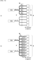
- FIG. 17 illustrates a transceiver unit model in a wireless communication system to which the present invention may be applied.
- M TXRU TXRUs are related to M antenna elements configured in a single column antenna array having the same polarization.
- a TXRU virtualization model may be divided into a TXRU virtualization model option-1: sub-array partition model as in FIG. 17(a) and a TXRU virtualization model option-2: full connection model as in FIG. 17(b) depending on a correlation between an antenna element and a TXRU.
- an antenna element is partitioned into multiple antenna element groups, and each TXRU is connected to one of the groups.
- vertical beamforming is applied to the CSI-RS resource that corresponds to the first with a zenith angle of 100 degrees, and CSI-RS is configured with an interval of a zenith angle of 5 degrees sequentially in each CSI-RS resource, and vertical beamforming is applied to the CSI-RS resource that corresponds to the eighth with a zenith angle of 135 degrees.
- a UE may report RI to an eNB in the first instance, report W1 to an eNB in the second instance, report W2 (or CQI) in the third instance, and report CQI (or W2) to an eNB in the fourth instance.
- a new reporting type (e.g., type 6a, RI+PTI+W13 or RI+PTI+W12) is defined and operates as below even in P-CSI mode 2-1.
- a period of each higher instance may be an integer multiple of a period the next lower instance.
- a period of the second instance may be an integer multiple of a period of the third instance.
- a period of each higher instance may be an integer multiple of a period the next lower instance.
- a period of the second instance may be an integer multiple of a period of the third instance.
- a UE may report RI and PTI (or RI, PTI and CRI) to an eNB in the first instance.
- PTI 0
- a UE may report W1 to an eNB in the second instance, and report CQI and WB W2 to an eNB in the third instance.
- a UE may report RI and PTI (or RI, PTI and CRI) to an eNB in the first instance.
- PTI 1
- a UE may report WB CQI and W2 to an eNB in the second instance, and report SB CQI, W2 and L' to an eNB in the third instance.
- a period of each higher instance may be an integer multiple of a period the next lower instance.
- a period of the second instance may be an integer multiple of a period of the third instance.
- L' is a subband (SB) selection index of a bandwidth part (BP).
- PTI 1
- Class B is a legacy operation
- P-CSI mode 1-1 submode 1 is applied in the second reporting instance as below.
- a single entire report includes two reporting times/instances on PUCCH format 2/2a/2b.
- a UE may report RI and W1 (or RI, CRI and W1) to an eNB in the first instance, and report CQI and W2 to an eNB in the second instance.
- a period of each higher instance may be an integer multiple of a period the next lower instance.
- a period of the first instance may be an integer multiple of a period of the second instance.
- the legacy P-CSI mode 1-1 may be used in the same way.
- modified P-CSI mode 1-1 is as below.
- a single entire report includes three reporting times/instances on PUCCH format 2/2a/2b.
- a UE may report CRI to an eNB in the first instance, report RI and W1 to an eNB in the second instance, and report CQI and W2 to an eNB in the third instance.
- a period of each higher instance may be an integer multiple of a period the next lower instance.
- a period of the second instance may be an integer multiple of a period of the third instance.
- the payload size is 8 bit, and accordingly, subsampling is not required.
- subsampling may be applied by a method exemplified in Table 40 below.
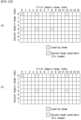
- Class B may also be distinguished into leading beam selection subsampling, second beam selection subsampling and power coefficient subsampling, as described above, and the case of reducing 2 bits using the three factors is as represented in Table 40 below.
- the case that the maximum number of second beam candidates is 3 is the same as the beam pattern of proposal 2-1, and the case that the maximum number of second beam candidates is 2 may include the example of proposal 2-5 or 2-6.
- the case that the maximum number of second beam candidates is 1 that a specific second beam is selected in the beam pattern of proposal 2-1, which may be promised between an eNB and a UE in advance.
- the power coefficient may also include the example of p 1 ⁇ 1 0.5 or p 1 ⁇ ⁇ 1, 0 ⁇ in the case that the number of the Second beam power coefficients is 2, corresponding to the case that subsampling is not performed when the number of the Second beam power coefficients is 4.
- a specific second beam power value e.g., 1 between an eNB and a UE, or configured to a UE by higher layer signaling (e.g., RRC or MAC CE).
- Table 41 is the same as the beam pattern of proposal 2-1, and when the maximum number of second beam candidates is 2, Table 41 may include the example of proposal 2-5 or 2-6. Further, when the maximum number of second beam candidates is 1, it may be promised in advance that a specific one second beam is selected within the beam pattern of 2-1.
- the power coefficient may also include the example of p 1 ⁇ 1 0.5 or p 1 ⁇ ⁇ 1, 0 ⁇ in the case that the number of the Second beam power coefficients is 2, corresponding to no-subsampling when the number of the Second beam power coefficients is 4.
- a specific second beam power value e.g., 1 between an eNB and a UE, or configured to a UE by higher layer signaling (e.g., RRC or MAC CE).
- W1 reporting type 2a
- PF3 for Class A 12-port or more in which subsampling is required.
- reporting type 2b wideband CQI + W2
- reporting type 2b may be reported with PF3.
- reporting type 1a (subband CQI + W2 + L') may be reported with PF3 regardless of Rank.
- FIG. 23 is a diagram illustrating a method for transmitting and receiving channel state information according to an embodiment of the present invention.
- the CSI may include selection information indicating a plurality of codewords used for generating a precoding matrix, information indicating the power coefficient, and/or information indicating the phase coefficient. Further, the types of information may be reported in different CSI reporting times/instances.
- a precoding matrix may include a first precoding vector for a first layer and a second precoding vector for a second layer.
- the first precoding vector may include a vector in which a first codeword and a second codeword are linearly combined for a first polarization and a vector in which a third codeword and a fourth codeword are linearly combined for a second polarization
- the second procoding vector include a vector in which a fifth codeword and a sixth codeword are linearly combined for a first polarization and a vector in which a seventh codeword and an eighth codeword are linearly combined for a second polarization.
- phase coefficient value (e.g., 1) applied to the first codeword and the fifth codeword may be predefined. Further, only the phase coefficient values applied to the second codeword, the third codeword, the fourth codeword, the sixth codeword, the seventh codeword and the eighth codeword may be determined by the second PMI.
- phase coefficient values applied to the second codeword and the sixth codeword may be determined by the second PMI within ⁇ 1, -1, j, -j ⁇ .
- the phase coefficient value applied to each of two codewords among the remaining codewords may be predetermined by the second PMI within two components (e.g., ⁇ 1, j ⁇ ).
- phase coefficient values that are predetermined or applied to the remaining codewords not determined by the second PMI may be determined according to a predetermined rule.
- the phase coefficient values applied to the fourth codeword and the eighth codeword may be determined based on the phase coefficient values applied to the third codeword and the seventh codeword.
- the phase coefficient value applied to the seventh codeword may be the same as the value of the phase coefficient value applied to the third codeword multiplied by -1.
- the UE may transmit the CSI to the eNB when operating periodic (or aperiodic) CSI reporting.
- FIG. 24 illustrates a block diagram of a wireless communication device according to an embodiment of the present invention.
- the eNB 2410 includes a processor 2411, memory 2412, and a Radio Frequency (RF) unit 2413.
- the processor 2411 implements the functions, processes and/or methods proposed with reference to FIGS. 1 to 23 .
- the layers of the radio interface protocol may be implemented by the processor 2411.
- the memory 2412 is connected to the processor 2411 and stores various types of information for driving the processor 2411.
- the RF unit 2413 is connected to the processor 2411 and sends and/or receives radio signals.
- the memory 2412, 2422 may be placed inside or outside the processor 2411, 2421 and may be connected to the processor 2411, 2421 by well-known various means. Furthermore, the eNB 2410 and/or the UE 2420 may have a single antenna or multiple antennas.
- an embodiment of the present invention may be implemented in the form of a module, procedure, or function for performing the aforementioned functions or operations.
- Software code may be stored in the memory and driven by the processor.
- the memory may be placed inside or outside the processor, and may exchange data with the processor through a variety of known means.
- the present invention has been illustrated as being applied to 3GPP LTE/LTE-A systems, but may be applied to various wireless communication systems other than the 3GPP LTE/LTE-A systems.
Landscapes
- Engineering & Computer Science (AREA)
- Computer Networks & Wireless Communication (AREA)
- Signal Processing (AREA)
- Physics & Mathematics (AREA)
- Mathematical Physics (AREA)
- Power Engineering (AREA)
- Mobile Radio Communication Systems (AREA)
Claims (4)
- Procédé pour rapporter des informations d'état de canal, « Channel State Information » CSI, réalisé par un équipement utilisateur, « User Equipment » UE, (2420) dans un système de communication sans fil, le procédé comprenant les faits :de recevoir, en provenance d'une station de base, « Base Station » BS, (2410), un signal de référence d'informations d'état de canal, « Channel State Information Reference Signal » CSI-RS, par le biais de multiples ports d'antenne ; etde rapporter, à la BS (2410), les CSI en utilisant un canal de commande de liaison montante physique, « Physical Uplink Control Channel » PUCCH, format 2,dans lequel les CSI incluent i) un indicateur de rang, « Rank Indicator » RI, ii) un indicateur de matrice de précodage, « Precoding Matrix Indicator » PMI, et iii) un indicateur de qualité de canal, « Channel Quality Indicator » CQI,dans lequel le PMI inclut des premières informations de PMI et des secondes informations de PMI, et dans lequel le RI, les premières informations de PMI et le CQI + les secondes informations de PMI sont transmis dans trois différentes instances de rapport de CSI,dans lequel les premières informations de PMI incluent i) un indice de faisceau de tête, ii) des informations pour sélectionner un second faisceau pour une combinaison linéaire et iii) des informations pour un coefficient de combinaison de puissance du second faisceau,dans lequel les secondes informations de PMI incluent des coefficients de combinaison appliqués à un faisceau de tête et au second faisceau,dans lequel une taille de charge utile de l'indice de faisceau de tête est déterminée par
 dans lequel chacun de N1 et de N2 est un nombre de ports d'antenne pour chaque polarisation dans chacune d'une première dimension et d'une seconde dimension, et un nombre des multiples ports d'antenne est 2*N1*N2,dans lequel chacun de O1 et de O2 est un facteur de suréchantillonnage dans chacune de la première dimension et de la seconde dimension,dans lequel le coefficient de puissance du second faisceau est un de 1, de
 dans lequel, lorsque le nombre des multiples ports d'antenne est de 12 ou de 16 :(O1, O2) incluent i) (4, 2) pour N1 supérieur à N2, ii) (2,4) pour N2 supérieur à N1, et iii) (2,2) pour N1 égal à N2,une taille de charge utile des informations pour le coefficient de puissance du second faisceau est de 1 bit, etle coefficient de puissance du second faisceau est i) un de 1 et de
 dans lequel, lorsque le nombre des multiples ports d'antenne est de 20, de 24, de 28, ou de 32 :(O1, O2) incluent i) (4, 2) pour N1 égal ou supérieur à N2, ii) (2,4) pour N2 supérieur à N1,la taille de charge utile des informations pour le coefficient de puissance du second faisceau est de 0 bit et le coefficient de puissance du second faisceau est configuré pour être 1.
 - Équipement utilisateur, « User Equipment » UE, (2420) configuré pour réaliser toutes les étapes d'un procédé selon la revendication 1.
- Procédé pour recevoir des informations d'état de canal, « Channel State Information » CSI, réalisé par une station de base, « Base Station » BS, (2410), dans un système de communication sans fil, le procédé comprenant les faits :de transmettre, à un équipement utilisateur, « User Equipment » UE, (2420), un signal de référence d'informations d'état de canal, « Channel State Information Reference Signal » CSI-RS, par le biais de multiples ports d'antenne ; etde recevoir, en provenance de l'UE (2420), les CSI en utilisant un canal de commande de liaison montante physique, « Physical Uplink Control Channel » PUCCH, format 2,dans lequel les CSI incluent i) un indicateur de rang, « Rank Indicator » RI, ii) un indicateur de matrice de précodage, « Precoding Matrix Indicator » PMI, et iii) un indicateur de qualité de canal, « Channel Quality Indicator » CQI,dans lequel le PMI inclut des premières informations de PMI et des secondes informations de PMI, et dans lequel le RI, les premières informations de PMI et le CQI + les secondes informations de PMI sont transmis dans trois différentes instances de rapport de CSI,dans lequel les premières informations de PMI incluent i) un indice de faisceau de tête, ii) des informations pour sélectionner un second faisceau pour une combinaison linéaire et iii) des informations pour un coefficient de combinaison de puissance du second faisceau,dans lequel les secondes informations de PMI incluent des coefficients de combinaison appliqués à un faisceau de tête et au second faisceau,dans lequel une taille de charge utile de l'indice de faisceau de tête est déterminée par
 dans lequel chacun de N1 et de N2 est un nombre de ports d'antenne pour chaque polarisation dans chacune d'une première dimension et d'une seconde dimension, et un nombre des multiples ports d'antenne est 2*N1*N2,dans lequel chacun de O1 et de O2 est un facteur de suréchantillonnage dans chacune de la première dimension et de la seconde dimension,dans lequel le coefficient de puissance du second faisceau est un de 1, de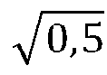
 dans lequel, lorsque le nombre des multiples ports d'antenne est de 12 ou de 16 :(O1, O2) incluent i) (4, 2) pour N1 supérieur à N2, ii) (2,4) pour N2 supérieur à N1, et iii) (2,2) pour N1 égal à N2,une taille de charge utile des informations pour le coefficient de puissance du second faisceau est de 1 bit et le coefficient de puissance du second faisceau est i) un de 1 et de
 dans lequel, lorsque le nombre des multiples ports d'antenne est de 20, de 24, de 28, ou de 32 :(O1, O2) incluent i) (4, 2) pour N1 égal ou supérieur à N2, ii) (2,4) pour N2 supérieur à N1,la taille de charge utile des informations pour le coefficient de puissance du second faisceau est de 0 bit et le coefficient de puissance du second faisceau est configuré pour être 1.
 - Station de base, « Base Station » BS, (2410) configurée pour réaliser toutes les étapes d'un procédé selon la revendication 3.
Applications Claiming Priority (6)
| Application Number | Priority Date | Filing Date | Title |
|---|---|---|---|
| US201662400066P | 2016-09-26 | 2016-09-26 | |
| US201662417257P | 2016-11-03 | 2016-11-03 | |
| US201762453002P | 2017-02-01 | 2017-02-01 | |
| US201762454879P | 2017-02-05 | 2017-02-05 | |
| PCT/KR2017/010613 WO2018056786A1 (fr) | 2016-09-26 | 2017-09-26 | Procédé de transmission/réception d'informations d'état de canal dans un système de communications sans fil, et appareil associé |
| EP17853500.1A EP3477874A4 (fr) | 2016-09-26 | 2017-09-26 | Procédé de transmission/réception d'informations d'état de canal dans un système de communications sans fil, et appareil associé |
Related Parent Applications (1)
| Application Number | Title | Priority Date | Filing Date |
|---|---|---|---|
| EP17853500.1A Division EP3477874A4 (fr) | 2016-09-26 | 2017-09-26 | Procédé de transmission/réception d'informations d'état de canal dans un système de communications sans fil, et appareil associé |
Publications (2)
| Publication Number | Publication Date |
|---|---|
| EP3955473A1 EP3955473A1 (fr) | 2022-02-16 |
| EP3955473B1 true EP3955473B1 (fr) | 2025-07-02 |
Family
ID=61690995
Family Applications (2)
| Application Number | Title | Priority Date | Filing Date |
|---|---|---|---|
| EP17853500.1A Withdrawn EP3477874A4 (fr) | 2016-09-26 | 2017-09-26 | Procédé de transmission/réception d'informations d'état de canal dans un système de communications sans fil, et appareil associé |
| EP21193347.8A Active EP3955473B1 (fr) | 2016-09-26 | 2017-09-26 | Procédé de transmission et de réception d'informations d'état de canal dans un système de communication sans fil et appareil associé |
Family Applications Before (1)
| Application Number | Title | Priority Date | Filing Date |
|---|---|---|---|
| EP17853500.1A Withdrawn EP3477874A4 (fr) | 2016-09-26 | 2017-09-26 | Procédé de transmission/réception d'informations d'état de canal dans un système de communications sans fil, et appareil associé |
Country Status (6)
| Country | Link |
|---|---|
| US (1) | US11088732B2 (fr) |
| EP (2) | EP3477874A4 (fr) |
| JP (1) | JP2019537300A (fr) |
| KR (1) | KR102015650B1 (fr) |
| CN (1) | CN109565323B (fr) |
| WO (1) | WO2018056786A1 (fr) |
Families Citing this family (29)
| Publication number | Priority date | Publication date | Assignee | Title |
|---|---|---|---|---|
| EP3518435A1 (fr) * | 2015-01-07 | 2019-07-31 | LG Electronics Inc. | Procédé de signalisation d'informations sur la qualité de canal dans un système de communication sans fil de type tdd et dispositif associé |
| WO2017075803A1 (fr) * | 2015-11-06 | 2017-05-11 | Qualcomm Incorporated | Traitement et création de rapport de rétroaction de csi pour eb/fd mimo |
| US10687296B2 (en) * | 2017-03-24 | 2020-06-16 | Qualcomm Incorporated | Techniques for communicating synchronization signal block index in a physical broadcast channel payload |
| CN112771973B (zh) * | 2018-08-01 | 2025-02-18 | 松下电器(美国)知识产权公司 | 终端、通信方法、基站以及集成电路 |
| CN110535511B (zh) * | 2018-09-04 | 2022-08-19 | 中兴通讯股份有限公司 | 一种定位参考信号传输方法和装置 |
| EP3874614A4 (fr) * | 2018-11-01 | 2022-08-31 | INTEL Corporation | Compression d'informations d'état de canal dans le domaine fréquentiel |
| EP3672096A1 (fr) * | 2018-12-22 | 2020-06-24 | Fraunhofer Gesellschaft zur Förderung der angewandten Forschung e.V. | Procédés et appareils de communication d'informations de retour dans un réseau de communications sans fil |
| US20190149294A1 (en) * | 2019-01-14 | 2019-05-16 | Intel IP Corporation | Csi-rs sequence generation and mapping and dmrs scrambling id configuration |
| WO2020150700A1 (fr) * | 2019-01-18 | 2020-07-23 | Apple Inc. | Compression d'informations d'état de canal (csi) dans le domaine fréquentiel |
| WO2020164108A1 (fr) * | 2019-02-15 | 2020-08-20 | Qualcomm Incorporated | Indication de coefficient pour des informations d'état de canal |
| CN111669823B (zh) * | 2019-03-07 | 2022-11-25 | 上海朗帛通信技术有限公司 | 一种被用于无线通信的节点中的方法和装置 |
| CN111756422B (zh) * | 2019-03-29 | 2023-03-03 | 华为技术有限公司 | 指示信道状态信息的方法以及通信装置 |
| AU2019438745B2 (en) | 2019-04-04 | 2023-02-02 | Nokia Technologies Oy | Uplink control information |
| CN111615142B (zh) * | 2019-04-30 | 2023-09-22 | 维沃移动通信有限公司 | 信道状态信息csi报告的传输方法、终端及网络设备 |
| EP3734852A1 (fr) * | 2019-05-02 | 2020-11-04 | Fraunhofer Gesellschaft zur Förderung der angewandten Forschung e.V. | Procédés et appareils de reporting csi dans un système de communication sans fil |
| US10992341B2 (en) * | 2019-06-17 | 2021-04-27 | Nokia Solutions And Networks Oy | Low-complexity beamforming for a multi-line communication system |
| US12199723B2 (en) * | 2019-08-12 | 2025-01-14 | Ntt Docomo, Inc. | Channel state information (CSI) omission procedure for rel. 16 type II CSI |
| EP3780455A1 (fr) * | 2019-08-15 | 2021-02-17 | Fraunhofer Gesellschaft zur Förderung der angewandten Forschung e.V. | Rapports csi basés sur un livre de codes à trois composants |
| JP7377342B2 (ja) | 2019-08-15 | 2023-11-09 | エルジー エレクトロニクス インコーポレイティド | 無線通信システムにおけるチャネル状態情報を報告する方法、及びこれに対する装置 |
| CN111836309B (zh) * | 2019-08-23 | 2023-10-24 | 维沃移动通信有限公司 | 信道状态信息csi报告的传输方法、终端及网络侧设备 |
| WO2021042318A1 (fr) * | 2019-09-05 | 2021-03-11 | Zte Corporation | Schéma de modulation pour rapport de puissance de crête sur puissance moyenne (papr) faible |
| WO2021147111A1 (fr) * | 2020-01-23 | 2021-07-29 | 华为技术有限公司 | Procédé de communication et appareil de communication |
| US12334999B2 (en) * | 2020-03-06 | 2025-06-17 | Lenovo (Singapore) Pte. Ltd. | Type-II port-selection codebook generation |
| CN116325533A (zh) * | 2020-10-02 | 2023-06-23 | 联想(新加坡)私人有限公司 | 基于传输假设来报告信道状态信息 |
| CN115348677B (zh) * | 2021-05-12 | 2026-02-10 | 北京紫光展锐通信技术有限公司 | 一种信息传输方法及相关产品 |
| EP4427368A4 (fr) * | 2021-11-05 | 2025-02-19 | Panasonic Intellectual Property Corporation of America | Appareil de communication et procédé de communication pour retour d'informations d'état de canal partiel |
| US11956171B2 (en) * | 2021-12-08 | 2024-04-09 | Qualcomm Incorporated | Cyclic shift reporting for a reference signal |
| CN116938294A (zh) * | 2022-03-31 | 2023-10-24 | 上海华为技术有限公司 | 一种数据传输方法以及装置 |
| US20260045979A1 (en) * | 2022-08-04 | 2026-02-12 | Beijing Xiaomi Mobile Software Co., Ltd. | Precoding matrix determination method and apparatus for uplink mimo transmission |
Family Cites Families (14)
| Publication number | Priority date | Publication date | Assignee | Title |
|---|---|---|---|---|
| KR101835326B1 (ko) * | 2010-09-26 | 2018-03-07 | 엘지전자 주식회사 | 다중 안테나 지원 무선 통신 시스템에서 효율적인 피드백 방법 및 장치 |
| US9544803B2 (en) * | 2011-04-20 | 2017-01-10 | Lg Electronics Inc. | Method for reporting channel state information in a wireless communication system, and apparatus therefor |
| WO2014042684A1 (fr) * | 2012-09-11 | 2014-03-20 | Ntt Docomo, Inc. | Procédé et appareil de dissémination efficace d'informations d'état de canal pour des méthodes de transmission mu-mimo basées sur des informations d'état de canal périmées |
| CN104662811B (zh) * | 2012-09-18 | 2018-05-01 | Lg电子株式会社 | 在多天线无线通信系统中发送有效反馈的方法及其设备 |
| US9143212B2 (en) * | 2013-02-25 | 2015-09-22 | Texas Instruments Incorporated | Codebook sub-sampling for CSI feedback on PUCCH for 4Tx MIMO |
| WO2014142504A1 (fr) * | 2013-03-11 | 2014-09-18 | 엘지전자 주식회사 | Procédé et appareil de rapport d'informations d'état de canal dans un système de communication sans fil |
| US9847818B2 (en) * | 2013-06-07 | 2017-12-19 | Nec Corporation | Channel state information (CSI) feedback and subsampling |
| US9667328B2 (en) * | 2014-03-31 | 2017-05-30 | Samsung Electronics Co., Ltd. | Precoding matrix codebook design and periodic channel state information feedback for advanced wireless communication systems |
| US20160072562A1 (en) | 2014-09-10 | 2016-03-10 | Samsung Electronics Co., Ltd. | Channel state information reporting with basis expansion for advanced wireless communications systems |
| US9825742B2 (en) * | 2014-10-03 | 2017-11-21 | Samsung Electronics Co., Ltd. | Codebook design and structure for advanced wireless communication systems |
| US9654195B2 (en) * | 2014-11-17 | 2017-05-16 | Samsung Electronics Co., Ltd. | Methods to calculate linear combination pre-coders for MIMO wireless communication systems |
| US10164747B2 (en) * | 2015-05-29 | 2018-12-25 | Samsung Electronics Co., Ltd. | Method and apparatus for operating MIMO measurement reference signals and feedback |
| US9918317B2 (en) * | 2016-07-08 | 2018-03-13 | Alcatel-Lucent Usa Inc. | Apparatus configured to approximate a power coefficient in a cell-free massive MIMO wireless system and method of performing same |
| US11025322B2 (en) * | 2016-08-12 | 2021-06-01 | Telefonaktiebolaget Lm Ericsson (Publ) | Progressive advanced CSI feedback |
-
2017
- 2017-09-26 CN CN201780047865.5A patent/CN109565323B/zh active Active
- 2017-09-26 EP EP17853500.1A patent/EP3477874A4/fr not_active Withdrawn
- 2017-09-26 KR KR1020187019889A patent/KR102015650B1/ko active Active
- 2017-09-26 EP EP21193347.8A patent/EP3955473B1/fr active Active
- 2017-09-26 JP JP2019516522A patent/JP2019537300A/ja active Pending
- 2017-09-26 US US16/065,085 patent/US11088732B2/en active Active
- 2017-09-26 WO PCT/KR2017/010613 patent/WO2018056786A1/fr not_active Ceased
Also Published As
| Publication number | Publication date |
|---|---|
| EP3477874A4 (fr) | 2020-04-08 |
| CN109565323B (zh) | 2022-08-02 |
| US11088732B2 (en) | 2021-08-10 |
| EP3955473A1 (fr) | 2022-02-16 |
| CN109565323A (zh) | 2019-04-02 |
| KR102015650B1 (ko) | 2019-10-21 |
| JP2019537300A (ja) | 2019-12-19 |
| EP3477874A1 (fr) | 2019-05-01 |
| US20190007106A1 (en) | 2019-01-03 |
| WO2018056786A1 (fr) | 2018-03-29 |
| KR20180086504A (ko) | 2018-07-31 |
Similar Documents
| Publication | Publication Date | Title |
|---|---|---|
| EP3955473B1 (fr) | Procédé de transmission et de réception d'informations d'état de canal dans un système de communication sans fil et appareil associé | |
| US10790888B2 (en) | Method for transmitting and receiving channel state information in multi-antenna wireless communication system, and apparatus therefor | |
| US11316566B2 (en) | Codebook-based signal transmission/reception method in multi-antenna wireless communication system, and device for same | |
| US10911110B2 (en) | Method for transceiving channel state information and apparatus therefor in multiple-antenna wireless communication system | |
| US10819412B2 (en) | Codebook-based signal transmission/reception method in multi-antenna wireless communication system, and device for same | |
| KR102338306B1 (ko) | 무선 통신 시스템에서 채널 상태 정보 송수신 방법 및 이를 위한 장치 | |
| EP3327943B1 (fr) | Procédé d'émission et de réception de signal à base de livre de codes dans un système de communication sans fil à antennes multiples et appareil associé | |
| EP3327945B1 (fr) | Procédé d'émission et de réception de signal à base de livre de codes dans un système de communication sans fil à antennes multiples et appareil associé | |
| EP3335364B1 (fr) | Procédé et appareil pour rapport de csi sur pucch | |
| EP3306881B1 (fr) | Procédé de mesure de canal dans un système de communication sans fil et appareil correspondant | |
| US10944183B2 (en) | Method for transmitting and receiving channel state information in multi-antenna wireless communication system, and device therefor | |
| EP3896866A1 (fr) | Procédé et appareil pour notification csi de rang supérieur dans des systèmes de communication sans fil | |
| US9948378B2 (en) | Method and device for transmitting reference signal in multi-antenna supporting wireless communication system | |
| WO2017014486A1 (fr) | Procédé permettant de rapporter des informations d'état de canal (csi) dans un système de communication sans fil et dispositif associé |
Legal Events
| Date | Code | Title | Description |
|---|---|---|---|
| PUAI | Public reference made under article 153(3) epc to a published international application that has entered the european phase |
Free format text: ORIGINAL CODE: 0009012 |
|
| STAA | Information on the status of an ep patent application or granted ep patent |
Free format text: STATUS: THE APPLICATION HAS BEEN PUBLISHED |
|
| AC | Divisional application: reference to earlier application |
Ref document number: 3477874 Country of ref document: EP Kind code of ref document: P |
|
| AK | Designated contracting states |
Kind code of ref document: A1 Designated state(s): AL AT BE BG CH CY CZ DE DK EE ES FI FR GB GR HR HU IE IS IT LI LT LU LV MC MK MT NL NO PL PT RO RS SE SI SK SM TR |
|
| STAA | Information on the status of an ep patent application or granted ep patent |
Free format text: STATUS: REQUEST FOR EXAMINATION WAS MADE |
|
| 17P | Request for examination filed |
Effective date: 20220420 |
|
| RBV | Designated contracting states (corrected) |
Designated state(s): AL AT BE BG CH CY CZ DE DK EE ES FI FR GB GR HR HU IE IS IT LI LT LU LV MC MK MT NL NO PL PT RO RS SE SI SK SM TR |
|
| STAA | Information on the status of an ep patent application or granted ep patent |
Free format text: STATUS: EXAMINATION IS IN PROGRESS |
|
| 17Q | First examination report despatched |
Effective date: 20240305 |
|
| GRAP | Despatch of communication of intention to grant a patent |
Free format text: ORIGINAL CODE: EPIDOSNIGR1 |
|
| STAA | Information on the status of an ep patent application or granted ep patent |
Free format text: STATUS: GRANT OF PATENT IS INTENDED |
|
| INTG | Intention to grant announced |
Effective date: 20250319 |
|
| GRAS | Grant fee paid |
Free format text: ORIGINAL CODE: EPIDOSNIGR3 |
|
| GRAA | (expected) grant |
Free format text: ORIGINAL CODE: 0009210 |
|
| STAA | Information on the status of an ep patent application or granted ep patent |
Free format text: STATUS: THE PATENT HAS BEEN GRANTED |
|
| AC | Divisional application: reference to earlier application |
Ref document number: 3477874 Country of ref document: EP Kind code of ref document: P |
|
| AK | Designated contracting states |
Kind code of ref document: B1 Designated state(s): AL AT BE BG CH CY CZ DE DK EE ES FI FR GB GR HR HU IE IS IT LI LT LU LV MC MK MT NL NO PL PT RO RS SE SI SK SM TR |
|
| REG | Reference to a national code |
Ref country code: GB Ref legal event code: FG4D |
|
| REG | Reference to a national code |
Ref country code: CH Ref legal event code: EP |
|
| REG | Reference to a national code |
Ref country code: DE Ref legal event code: R096 Ref document number: 602017090386 Country of ref document: DE |
|
| REG | Reference to a national code |
Ref country code: IE Ref legal event code: FG4D |
|
| PGFP | Annual fee paid to national office [announced via postgrant information from national office to epo] |
Ref country code: DE Payment date: 20250908 Year of fee payment: 9 |
|
| REG | Reference to a national code |
Ref country code: NL Ref legal event code: MP Effective date: 20250702 |
|
| PG25 | Lapsed in a contracting state [announced via postgrant information from national office to epo] |
Ref country code: PT Free format text: LAPSE BECAUSE OF FAILURE TO SUBMIT A TRANSLATION OF THE DESCRIPTION OR TO PAY THE FEE WITHIN THE PRESCRIBED TIME-LIMIT Effective date: 20251103 |
|
| PG25 | Lapsed in a contracting state [announced via postgrant information from national office to epo] |
Ref country code: NL Free format text: LAPSE BECAUSE OF FAILURE TO SUBMIT A TRANSLATION OF THE DESCRIPTION OR TO PAY THE FEE WITHIN THE PRESCRIBED TIME-LIMIT Effective date: 20250702 |
|
| REG | Reference to a national code |
Ref country code: AT Ref legal event code: MK05 Ref document number: 1810472 Country of ref document: AT Kind code of ref document: T Effective date: 20250702 |
|
| PG25 | Lapsed in a contracting state [announced via postgrant information from national office to epo] |
Ref country code: IS Free format text: LAPSE BECAUSE OF FAILURE TO SUBMIT A TRANSLATION OF THE DESCRIPTION OR TO PAY THE FEE WITHIN THE PRESCRIBED TIME-LIMIT Effective date: 20251102 |
|
| PG25 | Lapsed in a contracting state [announced via postgrant information from national office to epo] |
Ref country code: NO Free format text: LAPSE BECAUSE OF FAILURE TO SUBMIT A TRANSLATION OF THE DESCRIPTION OR TO PAY THE FEE WITHIN THE PRESCRIBED TIME-LIMIT Effective date: 20251002 |
|
| REG | Reference to a national code |
Ref country code: LT Ref legal event code: MG9D |
|
| PG25 | Lapsed in a contracting state [announced via postgrant information from national office to epo] |
Ref country code: AT Free format text: LAPSE BECAUSE OF FAILURE TO SUBMIT A TRANSLATION OF THE DESCRIPTION OR TO PAY THE FEE WITHIN THE PRESCRIBED TIME-LIMIT Effective date: 20250702 |
|
| PG25 | Lapsed in a contracting state [announced via postgrant information from national office to epo] |
Ref country code: FI Free format text: LAPSE BECAUSE OF FAILURE TO SUBMIT A TRANSLATION OF THE DESCRIPTION OR TO PAY THE FEE WITHIN THE PRESCRIBED TIME-LIMIT Effective date: 20250702 |
|
| PG25 | Lapsed in a contracting state [announced via postgrant information from national office to epo] |
Ref country code: HR Free format text: LAPSE BECAUSE OF FAILURE TO SUBMIT A TRANSLATION OF THE DESCRIPTION OR TO PAY THE FEE WITHIN THE PRESCRIBED TIME-LIMIT Effective date: 20250702 |
|
| PG25 | Lapsed in a contracting state [announced via postgrant information from national office to epo] |
Ref country code: GR Free format text: LAPSE BECAUSE OF FAILURE TO SUBMIT A TRANSLATION OF THE DESCRIPTION OR TO PAY THE FEE WITHIN THE PRESCRIBED TIME-LIMIT Effective date: 20251003 |
|
| PG25 | Lapsed in a contracting state [announced via postgrant information from national office to epo] |
Ref country code: SE Free format text: LAPSE BECAUSE OF FAILURE TO SUBMIT A TRANSLATION OF THE DESCRIPTION OR TO PAY THE FEE WITHIN THE PRESCRIBED TIME-LIMIT Effective date: 20250702 Ref country code: CZ Free format text: LAPSE BECAUSE OF FAILURE TO SUBMIT A TRANSLATION OF THE DESCRIPTION OR TO PAY THE FEE WITHIN THE PRESCRIBED TIME-LIMIT Effective date: 20250702 |
|
| PG25 | Lapsed in a contracting state [announced via postgrant information from national office to epo] |
Ref country code: LV Free format text: LAPSE BECAUSE OF FAILURE TO SUBMIT A TRANSLATION OF THE DESCRIPTION OR TO PAY THE FEE WITHIN THE PRESCRIBED TIME-LIMIT Effective date: 20250702 |
|
| PG25 | Lapsed in a contracting state [announced via postgrant information from national office to epo] |
Ref country code: PL Free format text: LAPSE BECAUSE OF FAILURE TO SUBMIT A TRANSLATION OF THE DESCRIPTION OR TO PAY THE FEE WITHIN THE PRESCRIBED TIME-LIMIT Effective date: 20250702 Ref country code: BG Free format text: LAPSE BECAUSE OF FAILURE TO SUBMIT A TRANSLATION OF THE DESCRIPTION OR TO PAY THE FEE WITHIN THE PRESCRIBED TIME-LIMIT Effective date: 20250702 |
|
| PG25 | Lapsed in a contracting state [announced via postgrant information from national office to epo] |
Ref country code: RS Free format text: LAPSE BECAUSE OF FAILURE TO SUBMIT A TRANSLATION OF THE DESCRIPTION OR TO PAY THE FEE WITHIN THE PRESCRIBED TIME-LIMIT Effective date: 20251002 |
|
| PG25 | Lapsed in a contracting state [announced via postgrant information from national office to epo] |
Ref country code: ES Free format text: LAPSE BECAUSE OF FAILURE TO SUBMIT A TRANSLATION OF THE DESCRIPTION OR TO PAY THE FEE WITHIN THE PRESCRIBED TIME-LIMIT Effective date: 20250702 |
|
| PG25 | Lapsed in a contracting state [announced via postgrant information from national office to epo] |
Ref country code: RO Free format text: LAPSE BECAUSE OF FAILURE TO SUBMIT A TRANSLATION OF THE DESCRIPTION OR TO PAY THE FEE WITHIN THE PRESCRIBED TIME-LIMIT Effective date: 20250702 |
|
| PG25 | Lapsed in a contracting state [announced via postgrant information from national office to epo] |
Ref country code: SM Free format text: LAPSE BECAUSE OF FAILURE TO SUBMIT A TRANSLATION OF THE DESCRIPTION OR TO PAY THE FEE WITHIN THE PRESCRIBED TIME-LIMIT Effective date: 20250702 |
|
| PG25 | Lapsed in a contracting state [announced via postgrant information from national office to epo] |
Ref country code: DK Free format text: LAPSE BECAUSE OF FAILURE TO SUBMIT A TRANSLATION OF THE DESCRIPTION OR TO PAY THE FEE WITHIN THE PRESCRIBED TIME-LIMIT Effective date: 20250702 |
|
| PG25 | Lapsed in a contracting state [announced via postgrant information from national office to epo] |
Ref country code: IT Free format text: LAPSE BECAUSE OF FAILURE TO SUBMIT A TRANSLATION OF THE DESCRIPTION OR TO PAY THE FEE WITHIN THE PRESCRIBED TIME-LIMIT Effective date: 20250702 |
|
| PG25 | Lapsed in a contracting state [announced via postgrant information from national office to epo] |
Ref country code: EE Free format text: LAPSE BECAUSE OF FAILURE TO SUBMIT A TRANSLATION OF THE DESCRIPTION OR TO PAY THE FEE WITHIN THE PRESCRIBED TIME-LIMIT Effective date: 20250702 Ref country code: SK Free format text: LAPSE BECAUSE OF FAILURE TO SUBMIT A TRANSLATION OF THE DESCRIPTION OR TO PAY THE FEE WITHIN THE PRESCRIBED TIME-LIMIT Effective date: 20250702 |