EP3955718B1 - Dispositif de montage de composant et procédé de montage de composant - Google Patents
Dispositif de montage de composant et procédé de montage de composant Download PDFInfo
- Publication number
- EP3955718B1 EP3955718B1 EP19924075.5A EP19924075A EP3955718B1 EP 3955718 B1 EP3955718 B1 EP 3955718B1 EP 19924075 A EP19924075 A EP 19924075A EP 3955718 B1 EP3955718 B1 EP 3955718B1
- Authority
- EP
- European Patent Office
- Prior art keywords
- shaft
- sleeve
- component
- elastic member
- section
- Prior art date
- Legal status (The legal status is an assumption and is not a legal conclusion. Google has not performed a legal analysis and makes no representation as to the accuracy of the status listed.)
- Active
Links
Images




Classifications
-
- H—ELECTRICITY
- H05—ELECTRIC TECHNIQUES NOT OTHERWISE PROVIDED FOR
- H05K—PRINTED CIRCUITS; CASINGS OR CONSTRUCTIONAL DETAILS OF ELECTRIC APPARATUS; MANUFACTURE OF ASSEMBLAGES OF ELECTRICAL COMPONENTS
- H05K13/00—Apparatus or processes specially adapted for manufacturing or adjusting assemblages of electric components
- H05K13/04—Mounting of components, e.g. of leadless components
- H05K13/0404—Pick-and-place heads or apparatus, e.g. with jaws
- H05K13/0413—Pick-and-place heads or apparatus, e.g. with jaws with orientation of the component while holding it; Drive mechanisms for gripping tools, e.g. lifting, lowering or turning of gripping tools
Definitions
- the present specification describes a technique related to a component mounting device and a component mounting method.
- a pickup member for picking up a component is supported so as to be lifted and lowered in a movable head unit.
- a tip portion of the pickup member is provided so as to be swingable by a predetermined amount in a direction in which the pickup member protrudes and retracts with respect to a main body portion of the pickup member, and is biased in a protruding state by an elastic member.
- the component conveyance device includes a detection means and a nozzle abnormality determination means.
- the detection means detects a position of the tip portion of the pickup member with respect to the main body portion of the pickup member.
- the nozzle abnormality determination means detects, based on the detection by the detection means, whether the position of the tip portion of the pickup member is within a normal range set in advance, and determines that there is an abnormality when the position of the tip portion of the pickup member is not within the normal range.
- the component conveyance device disclosed in Patent Literature 1 discriminates an abnormality caused by, for example, decrease in a buffing function of the tip portion of the pickup member.
- Patent Literature 2 measures the distance between a reference mark on a nozzle holder to a lower end of a nozzle during a pickup or mounting operation on an image taken by a side camera to detect whether a sliding movement of the nozzle relative to the nozzle holder is impeded.
- Patent Literature 3 and Patent Literature 4 disclose nozzle holders with a slidable nozzle biased downwards by a spring especially designed to handle components requiring a low mounting load.
- Patent Literature 1 detects the position of the tip portion of the pickup member with respect to the main body portion of the pickup member.
- the present specification describes a component mounting device and a component mounting method capable of more preferably detecting an abnormality of a component holding member by a technique different from the related art.
- the present specification discloses a component mounting device including a head main body, a shaft, a sleeve, a component holding section, a first elastic member, a second elastic member, a detecting section, and a controller.
- the shaft is provided on the head main body so as to be lifted and lowered.
- the sleeve is provided so as to be movable relative to the shaft in a vertical direction.
- the component holding section is provided so as to be movable relative to the sleeve in the vertical direction.
- the first elastic member biases the sleeve positioned at a lower end of the shaft toward a lower side in the vertical direction.
- the second elastic member biases the component holding section positioned at the lower end of the sleeve toward the lower side.
- the biasing force of the second elastic member is smaller than the biasing force of the first elastic member.
- the detecting section detects whether the sleeve has moved relative to the shaft when a component held by the component holding section is mounted to the board by lifting and lowering the shaft.
- the controller is configured to determine an abnormal state of movement resistance in case of a relative movement between the sleeve and the shaft against the biasing force of the first elastic member when the component is mounted on the board.
- the present specification discloses a component mounting method using a component mounting device including a head main body, a shaft, a sleeve, a component holding section, a first elastic member, and a second elastic member, in which the component mounting method includes a detecting step and a determining step.
- the shaft is provided on the head main body so as to be lifted and lowered.
- the sleeve is provided so as to be movable relative to the shaft in a vertical direction.
- the component holding section is provided so as to be movable relative to the sleeve in the vertical direction.
- the first elastic member biases the sleeve positioned at a lower end of the shaft toward a lower side in the vertical direction.
- the second elastic member biases the component holding section positioned at the lower end of the sleeve toward the lower side.
- the biasing force of the second elastic member is smaller than the biasing force of the first elastic member.
- the detecting step detects whether the sleeve has moved relative to the shaft when a component held by the component holding section is mounted to the board by lifting and lowering the shaft.
- the determining step determines an abnormal state of movement resistance in case of a relative movement between the sleeve and the shaft against the biasing force of the first elastic member when the component is mounted on the board.
- the component mounting device including the head main body, the shaft, the sleeve, the component holding section, the first elastic member, and the second elastic member includes the detecting section.
- the component mounting device can detect whether the sleeve has moved relative to the shaft when mounting the component to the board, so that it is possible to preferably detect an abnormality of the component holding member. Specifically, in a case where a movement resistance between the component holding section and the sleeve is small in a normal state of the component holding member, the sleeve does not move relative to the shaft against a biasing force of the first elastic member.
- the detecting section can preferably detect an abnormality of the component holding member by detecting that the sleeve has moved relative to the shaft.
- Component mounting device 10 mounts multiple components 91 on board 90. As shown in Fig. 1 , component mounting device 10 includes board conveyance device 11, component supply device 12, component transfer device 13, part camera 14, board camera 15, and control device 16.
- Board conveyance device 11 is configured by, for example, a belt conveyor or the like, and conveys board 90 in a conveyance direction (X-axis direction).
- Board 90 is a circuit board and at least one of an electronic circuit and an electrical circuit is formed.
- Board conveyance device 11 conveys board 90 into component mounting device 10 and positions board 90 at a predetermined position in component mounting device 10. After a mounting process of multiple components 91 by component mounting device 10 is ended, board conveyance device 11 conveys board 90 out of component mounting device 10.
- Component supply device 12 supplies multiple components 91 to be mounted on board 90.
- Component supply device 12 includes multiple feeders 121 that are provided along the conveyance direction of board 90 (X-axis direction). Each of multiple feeders 121 pitch-feeds a carrier tape (not shown) that stores multiple components 91 to supply component 91, so that component 91 are supplied at a supply position positioned on a distal end side of feeder 121 so as to be able to pick up.
- component supply device 12 can supply relatively large electronic components (for example, lead components) as compared with chip components or the like, in a state of being disposed on a tray.
- Component transfer device 13 includes head driving device 131 and moving body 132.
- Head driving device 131 is configured to move moving body 132 in the X-axis direction and the Y-axis direction by a linear motion mechanism.
- Mounting head 20 is detachably (exchangeably) provided to moving body 132 by a clamp member (not shown).
- Component mounting head 20 uses at least one component holding member 30 to pick up and hold component 91 supplied by component supply device 12, and mounts component 91 on board 90 positioned by board conveyance device 11.
- Component holding member 30, for example, a suction nozzle, a chuck, or the like can be used.
- Part camera 14 and board camera 15 a well-known imaging device can be used.
- Part camera 14 is fixed to a base of component mounting device 10 such that an optical axis faces upward in the vertical direction (Z-axis direction).
- Part camera 14 can capture an image of component 91 held by component holding member 30 from below.
- Board camera 15 is provided on moving body 132 of component transfer device 13 such that the optical axis faces downward in the vertical direction (the Z-axis direction).
- Board camera 15 can capture an image of board 90 from above.
- Part camera 14 and board camera 15 perform imaging based on control signals transmitted from control device 16. Image data captured by part camera 14 and board camera 15 is transmitted to control device 16.
- Control device 16 includes well-known computing device and storage device, and a control circuit is provided therein (both of which are not shown). Information, image data, and the like output from various sensors provided in component mounting device 10 are input to control device 16. Control device 16 transmits the control signals to each device based on a control program, a predetermined mounting condition which is set in advance, and the like.
- control device 16 causes board camera 15 to capture an image of board 90 that is positioned by board conveyance device 11. Control device 16 performs image processing with respect to the image captured by board camera 15 to recognize a positioning state of board 90. In addition, control device 16 causes component holding member 30 to pick up and hold component 91 supplied by component supply device 12, and causes part camera 14 to image component 91 held by component holding member 30. Control device 16 performs image processing with respect to the image captured by part camera 14 to recognize a holding posture of component 91.
- Control device 16 moves component holding member 30 toward an upper side from a scheduled mounting position which is set in advance by the control program or the like. In addition, control device 16 corrects the mounting planned position based on the positioning state of board 90, the holding posture of component 91, and the like, and sets a mounting position on which component 91 is actually mounted.
- the scheduled mounting position and mounting position include a rotation angle in addition to the position (X-axis coordinate and Y-axis coordinate).
- Control device 16 corrects a target position (X-axis coordinate and Y-axis coordinate) of component holding member 30 and the rotation angle in accordance with the mounting position. Control device 16 lowers component holding member 30 at the corrected rotation angle in the corrected target position, so that component 91 is mounted to board 90. Control device 16 repeats the pick- and-place cycle described above to execute the mounting process of mounting multiple components 91 on board 90.
- mounting head 20 includes head main body 21 clamped by moving body 132.
- Head main body 21 is provided with rotary head 23 such that a rotation angle can be indexed for each predetermined angle by R-axis motor 22.
- Rotary head 23 includes multiple tool shafts 24 (for example, twelve) at equal intervals in the circumferential direction on a circumference concentric with the R-axis.
- Rotary head 23 holds tool shaft 24 slidably in a ⁇ -axis direction (the vertical direction in Fig. 2 ) parallel to the Z-axis and the R-axis and rotatably around the ⁇ -axis.
- Tool shaft 24 is biased upward with respect to rotary head 23 by an elastic force of a spring (not shown). As a result, tool shaft 24 is positioned at a lifting end in an ordinary state where no external force is applied.
- Component holding member 30 is detachably attached to a lower end portion of tool shaft 24. At least positive pressure air or negative pressure air is supplied to component holding member 30 to pick up component 91. In addition, when component holding member 30 is attached, tool shaft 24 biases component holding member 30 downward by the elastic force of the elastic member described later.
- Each of multiple component holding members 30 holds component 91 by supplying air to an air passage of component holding member 30.
- Multiple component holding members 30 are sequentially indexed to predetermined angle positions around the R-axis (for example, lifting and lowering positions of tool shaft 24) by the rotation of rotary head 23 in accordance with the driving of R-axis motor 22.
- mounting head 20 includes ⁇ -axis motor 25 fixed to head main body 21. All tool shafts 24 are connected to an output shaft of ⁇ -axis motor 25 such that rotational force can be transmitted via multiple gears. Tool shaft 24 and component holding member 30 are rotated (rotated on its axis) integrally around the ⁇ -axis by the operation of ⁇ -axis motor 25, so that the rotation angle and the rotation speed are controlled.
- head main body 21 is provided with actuating member 26 so as to be movable in the vertical direction (the Z-axis direction).
- Actuating member 26 is lifted and lowered in the vertical direction (the Z-axis direction) by ball screw mechanism 28 operated by driving of Z-axis motor 27.
- Actuating member 26 includes lever 29 that can contact an upper end portion of tool shaft 24 that is indexed to the lifting and lowering position among multiple tool shafts 24.
- Lever 29 lowers in accordance with the downward movement of actuating member 26 in the vertical direction (the Z-axis direction).
- Lever 29 pushes tool shaft 24 downward in the vertical direction (the Z-axis direction) against the elastic force of the spring of tool shaft 24 in contact with lever 29, and causes tool shaft 24 to lower.
- Tool shaft 24 and component holding member 30 are integrally lifted and lowered in the vertical direction (the Z-axis direction) by the driving of Z-axis motor 27, so that the position and the movement speed in the vertical direction (the Z-axis direction) are controlled.
- tool shaft 24 of the present embodiment includes shaft 24a, first elastic member 24b, second elastic member 24c, and first member 24d.
- component holding member 30 includes sleeve 30a and component holding section 30b.
- shaft 24a is provided on head main body 21 so as to be lifted and lowered.
- sleeve 30a is provided so as to be movable relative to shaft 24a in the vertical direction (the Z-axis direction).
- first elastic member 24b biases sleeve 30a positioned at the lower end of shaft 24a toward the lower side in the vertical direction (the Z-axis direction).
- sleeve 30a provided inside shaft 24a includes protruding portion 30a1 protruding outwardly through shaft 24a.
- guide section 24a1 capable of guiding protruding portion 30a1 when sleeve 30a is attached to shaft 24a is formed on shaft 24a.
- Guide section 24a1 is formed in a groove shape and includes first groove section 24a11, second groove section 24a12, and third groove section 24a13.
- First groove section 24a11 is formed so as to extend from the lower end of shaft 24a toward the upper side in a vertical direction (the Z-axis direction).
- Second groove section 24a12 is formed so as to extend in a horizontal direction from an end portion of first groove section 24a11 on the side opposite to the lower end of shaft 24a.
- Third groove section 24a13 is formed so as to extend from an end portion of second groove section 24a12 on the side opposite to first groove section 24a11 toward the lower side in the vertical direction (the Z-axis direction).
- a cross-sectional area of guide section 24a1 obtained by cutting guide section 24a1 in a plane perpendicular to the guide direction of protruding portion 30a1 is formed to be slightly larger than a cross-sectional area of protruding portion 30a1. Accordingly, when sleeve 30a is attached to shaft 24a, protruding portion 30a1 indicated by dashed lines in Fig. 4 can enter guide section 24a1 from the lower end of shaft 24a and move to the end point of guide section 24a1 (the end of third groove section 24a13).
- First member 24d provided outside shaft 24a is a pressing member that presses protruding portion 30a1.
- first elastic member 24b of the present embodiment biases sleeve 30a toward the lower side via first member 24d. Accordingly, first member 24d is integrally movable with sleeve 30a.
- sleeve 30a is movable relative to shaft 24a in the vertical direction (the Z-axis direction).
- Component holding section 30b is provided so as to be movable relative to sleeve 30a in the vertical direction (the Z-axis direction). Specifically, component holding section 30b is provided inside sleeve 30a. In addition, second elastic member 24c biases component holding section 30b positioned at the lower end of sleeve 30a toward the lower side. Accordingly, component holding section 30b is movable relative to sleeve 30a in the vertical direction (the Z-axis direction). As shown in Fig. 5 , second elastic member 24c of the present embodiment biases component holding section 30b via the connection member, and second elastic member 24c is provided above first elastic member 24b in the vertical direction (the Z-axis direction). In addition, second elastic member 24c of the present embodiment biases component holding section 30b toward the lower side with a smaller biasing force than first elastic member 24b.
- component mounting device 10 of the present embodiment includes detecting section 16a.
- the biasing force of first elastic member 24b is set such that first elastic member 24b elastically deforms under a predetermined condition.
- control device 16 of component mounting device 10 includes detecting section 16a when viewed as a control block. Detecting section 16a detects whether sleeve 30a has moved relative to shaft 24a when component 91 held by component holding section 30b is mounted to board 90 by lifting and lowering shaft 24a.
- a state in which the movement resistance between component holding section 30b and sleeve 30a is equal to or less than a predetermined value is referred to as a normal state.
- a state in which the movement resistance between component holding section 30b and sleeve 30a exceeds a predetermined value is referred to as an abnormal state.
- the predetermined value of the movement resistance indicates an allowable value of the load applied to component 91, and can be derived at the time of designing first elastic member 24b by simulation, verification by an actual device, or the like.
- the biasing force of first elastic member 24b is preferably set such that first elastic member 24b elastically deforms when the movement resistance is in an abnormal state and shaft 24a lowers further after component 91 reaches board 90 in the mounting operation of mounting component 91 to board 90.
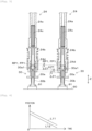
- Fig. 5 shows an example of a positional relationship between sleeve 30a and shaft 24a when the movement resistance is in a normal state.
- Fig. 5 is a cross-sectional view obtained by cutting tool shaft 24 taken along the axial line direction.
- Tool shaft 24 on the left side in Fig. 5 shows a state in which component 91 reaches board 90 in the mounting operation.
- Tool shaft 24 on the right side in Fig. 5 shows a state when shaft 24a lowers further from the state of tool shaft 24 on the left side.
- detecting section 16a detects that sleeve 30a has not moved relative to shaft 24a.
- the position of protruding portion 30a1 of tool shaft 24 on the right side in Fig. 5 lowers by deviation ⁇ Z1 in the vertical direction (the Z-axis direction) as compared with tool shaft 24 on the left side.
- the position of the lower end of shaft 24a of tool shaft 24 on the right side in Fig. 5 lowers by deviation ⁇ Z1 in the vertical direction (the Z-axis direction) as compared with tool shaft 24 on the left side.
- Fig. 6 shows an example of the time-dependent change in the positions of sleeve 30a and shaft 24a in the vertical direction (the Z-axis direction) when the movement resistance is in a normal state.
- a horizontal axis in Fig. 6 represents time, and a vertical axis represents the position (height) in the vertical direction (the Z-axis direction).
- Straight line L11 represents the position (height) in the vertical direction (the Z-axis direction) of protruding portion 30a1 when the movement resistance is in a normal state.
- Straight line L12 represents the position (height) in the vertical direction (the Z-axis direction) of the lower end of shaft 24a when the movement resistance is in a normal state.
- Fig. 2 shows that the movement resistance is in a normal state and sleeve 30a did not move relative to shaft 24a.
- Fig. 7 shows an example of the positional relationship between sleeve 30a and shaft 24a when the movement resistance is in an abnormal state.
- Fig. 5 is a cross-sectional view obtained by cutting tool shaft 24 taken along the axial line direction.
- Tool shaft 24 on the left side in Fig. 5 shows a state in which component 91 reaches board 90 in the mounting operation.
- Tool shaft 24 on the right side in Fig. 5 shows a state when shaft 24a lowers further from the state of tool shaft 24 on the left side.
- detecting section 16a detects that sleeve 30a has moved relative to shaft 24a against the biasing force of first elastic member 24b.
- the position of protruding portion 30a1 of tool shaft 24 on the right side in Fig. 7 is the same as that of tool shaft 24 on the left side, but the position of the lower end of shaft 24a of tool shaft 24 on the right side in Fig. 7 lowers by deviation ⁇ Z1 in the vertical direction (the Z-axis direction) as compared with tool shaft 24 on the left side.
- Fig. 8 shows an example of the time-dependent change in the positions of sleeve 30a and shaft 24a in the vertical direction (the Z-axis direction) when the movement resistance is in an abnormal state.
- a horizontal axis in Fig. 6 represents time, and a vertical axis represents the position (height) in the vertical direction (the Z-axis direction).
- Polygonal line L21 represents the position (height) in the vertical direction (the Z-axis direction) of protruding portion 30a1 when the movement resistance is in an abnormal state.
- Straight line L22 represents the position (height) in the vertical direction (the Z-axis direction) of the lower end of shaft 24a when the movement resistance is in an abnormal state.
- Fig. 8 shows that the movement resistance is in an abnormal state, and sleeve 30a has moved relative to shaft 24a.
- detecting section 16a detects whether sleeve 30a has moved relative to shaft 24a when component 91 held by component holding section 30b is mounted to board 90 by lifting and lowering shaft 24a.
- Component mounting device 10 can acquire the normal state of the movement resistance (the normal state of component holding member 30) when detecting section 16a detects that sleeve 30a has not moved relative to shaft 24a.
- component mounting device 10 can acquire the abnormal state of the movement resistance (abnormal state of component holding member 30) when detecting section 16a detects that sleeve 30a has moved relative to shaft 24a. In the latter case, component mounting device 10 can instruct the user to maintain component holding member 30.
- Component mounting device 10 preferably further includes feature section FP1 and imaging device 40.
- detecting section 16a preferably detects whether sleeve 30a has moved relative to shaft 24a based on the captured image of feature section FP1 captured by imaging device 40.
- Feature section FP1 is provided on at least one of first member 24d, sleeve 30a, and shaft 24a that is integrally movable with sleeve 30a.
- Feature section FP1 may have various forms as long as detecting section 16a can detect whether sleeve 30a has moved relative to shaft 24a.
- Feature section FP1 is preferably a figure, a character, a symbol, a three-dimensional shape or a color, or a combination thereof.
- feature section FP1 may include the figure.
- a name of a manufacturer, a type of a product, a lot number, a figure such as a reference conformance mark, a character, a symbol, or the like are appended on the outer peripheral portion of first member 24d
- feature section FP1 may include these.
- a three-dimensional shape such as a recessed section or a protruding portion is formed on the outer peripheral portion of first member 24d
- feature section FP1 may include these.
- a color of a part of the outer peripheral portion of first member 24d is different from another part
- feature section FP1 may include the color of the part.
- feature section FP1 may include a combination of two or more of a figure, a character, a symbol, a three-dimensional shape, and a color (referred to as a coupling feature section in the present description).
- the coupling feature section may be a mere combination of two or more of a figure, a character, a symbol, a three-dimensional shape, and a color, or may be a combination thereof.
- the stamping may be the coupling feature section in which a figure, a character, or a symbol is coupled to a three-dimensional shape.
- Imaging device 40 is fixed to head main body 21 and captures an image of feature section FP1.
- Imaging device 40 is preferably head camera unit 40a that captures an image of component 91 held by component holding section 30b from a lateral side.
- Fig. 2 shows a configuration example of head camera unit 40a, and schematically shows an inner portion of head camera unit 40a.
- head camera unit 40a is provided on mounting head 20, and integrally moves with mounting head 20 in accordance with the movement of moving body 132.
- Head camera unit 40a uses component holding member 30 attached to tool shaft 24, component 91 held by component holding member 30, and feature section FP1 as a subject.
- Head camera unit 40a irradiates the subject with light based on an imaging command by control device 16 of component mounting device 10 to image the subject from the lateral side.
- positions of two component holding members 30 adjacent to component holding member 30 positioned in lifting and lowering position H0 lifted and lowered by mounting head 20 are defined as front standby position H-1 and rear standby position H+1.
- Front standby position H-1 is a position at which component holding member 30 to be indexed next time to lifting and lowering position H0 by the rotation of rotary head 23 is placed in standby.
- Rear standby position H+1 is a position at which component holding member 30 previously indexed to lifting and lowering position H0 by the rotation of rotary head 23 is placed in standby.
- head camera unit 40a includes case 41, camera device 42, light source 43, reflection member 44, and optical member 45.
- Case 41 is provided so as to surround a part of multiple component holding members 30 disposed on the circumference of rotary head 23 from the outer peripheral side.
- Camera device 42 is provided on moving body 132 via mounting head 20. Camera device 42 captures images of two component holding members 30 positioned at front standby position H-1 and rear standby position H+1, and an image of component 91 held by component holding member 30 positioned at front standby position H-1.
- camera device 42 captures the image of feature section FP1 of tool shaft 24 including component holding member 30 indexed to lifting and lowering position H0.
- Light source 43 is disposed on a cylindrical inner peripheral surface of case 41 facing component holding member 30 and feature section FP1.
- Light source 43 performs irradiation of ultraviolet light in a center direction of rotary head 23 (direction toward the R-axis).
- Reflection member 44 is formed in a cylindrical shape and is disposed coaxially with the R-axis at a lower end of rotary head 23. Reflection member 44 reflects the ultraviolet light irradiated from light source 43 on the cylindrical outer peripheral surface to make visible light.
- light source 43 irradiates feature section FP1 with visible light without passing through reflection member 44.
- Optical member 45 is disposed inside case 41 to form a light path from a subject to camera device 42. Specifically, optical member 45 forms the light path such that two component holding members 30 irradiated with the reflected light reflected by reflection member 44 are contained in the camera visual field of camera device 42. In addition, optical member 45 forms the light path such that feature section FP1 of tool shaft 24 including component holding member 30 indexed to lifting and lowering position H0 is contained in the camera visual field described above.
- optical member 45 forms the light path such that the tip portion of two component holding members 30 indexed to front standby position H-1 and rear standby position H+1 and feature section FP1 of tool shaft 24 having component holding member 30 indexed to lifting and lowering position H0 are contained in the same camera visual field.
- head camera unit 40a can capture the images of component holding member 30, component 91, and feature section FP1 in the same camera visual field.
- Side view image data PD1 captured by camera device 42 is transmitted to control device 16.
- First region PD11 is a region where the image of the tip portion of component holding member 30 indexed to front standby position H-1 is captured.
- Second region PD12 is a region where the image of the tip portion of component holding member 30 indexed to rear standby position H+1 is captured.
- Third region PD13 is a region where the image of feature section FP1 of tool shaft 24 is captured when component holding member 30 indexed to lifting and lowering position H0 is lowered in the mounting process.
- Side view image data PD1 is captured such that a region where component holding member 30 and component 91 are present is shaded with reflection member 44 as a background.
- image processing such as binarization is executed in camera device 42 or control device 16, so that the contrast with the background is emphasized.
- feature section FP1 of the present embodiment is provided in first member 24d.
- feature section FP1 is a straight line attached to the outer peripheral portion of first member 24d.
- sleeve 30a provided on the inner side of shaft 24a includes protruding portion 30a1 protruding outward through shaft 24a.
- first member 24d provided outside shaft 24a is a pressing member that presses protruding portion 30a1.
- first elastic member 24b biases sleeve 30a toward the lower side via first member 24d.
- Detecting section 16a can acquire a change in the position (height) in the vertical direction (the Z-axis direction) of feature section FP1 with respect to reference position RP1 of shaft 24a based on the captured image of feature section FP1 captured by head camera unit 40a.
- Reference position RP1 of shaft 24a is a virtual position of shaft 24a in the captured image of feature section FP1 (third region PD13 shown in Fig. 10 ), and is lowered in conjunction with the mounting operation.
- Reference position RP1 of shaft 24a of the present embodiment is a part that is lowered in conjunction with the mounting operation at the same position (height) as the position (height) in the vertical direction (Z-axis direction) of feature section FP1 when the movement resistance is in the normal state.
- detecting section 16a detects that sleeve 30a has not moved relative to shaft 24a since the position (height) in the vertical direction (the Z-axis direction) of feature section FP1 is the same as reference position RP1 of shaft 24a.
- detecting section 16a detects that sleeve 30a has moved relative to shaft 24a against the biasing force of first elastic member 24b since the position (height) in the vertical direction (the Z-axis direction) of feature section FP1 differs from reference position RP1 of shaft 24a.
- Shaft 24a is lifted and lowered in the vertical direction (the Z-axis direction) by the driving of Z-axis motor 27 shown in Fig. 2 .
- detecting section 16a can acquire reference position RP1 of shaft 24a based on the detection result of a position detector (for example, an encoder or the like) provided in Z-axis motor 27.
- reference position RP1 of shaft 24a may be a position (height) that is spaced apart from feature section FP1 in the vertical direction (the Z-axis direction) by a predetermined amount when the movement resistance is in the normal state, and may be a part that is lowered in conjunction with the mounting operation.
- detecting section 16a detects whether sleeve 30a has moved relative to shaft 24a based on whether a distance between reference position RP1 of shaft 24a and the vertical direction (the Z-axis direction) of feature section FP1 is a predetermined amount.
- reference position RP1 of shaft 24a may be the position of feature section FP1 provided on shaft 24a captured by head camera unit 40a.
- detecting section 16a acquires the position (height) in the vertical direction (the Z-axis direction) between feature section FP1 provided on shaft 24a indicating reference position RP1 of shaft 24a and feature section FP1 provided on first member 24d.
- Detecting section 16a detects, for example, that sleeve 30a has not moved relative to shaft 24a when the position (height) in the vertical direction (the Z-axis direction) of feature section FP1 provided in first member 24d is the same as feature section FP1 (reference position RP1 of shaft 24a) provided in shaft 24a. Detecting section 16a detects that sleeve 30a has moved relative to shaft 24a when the position (height) in the vertical direction (the Z-axis direction) of feature section FP1 provided in first member 24d is different from feature section FP1 (reference position RP1 of shaft 24a) provided in shaft 24a.
- Feature section FP1 may also be provided in sleeve 30a.
- shaft 24a preferably includes a transmitting portion that transmits light.
- Sleeve 30a provided inside shaft 24a may extend to the transmitting portion.
- sleeve 30a may include an extension member extending from the main body portion to the transmitting portion of sleeve 30a.
- imaging device 40 can capture an image of feature section FP1 via the transmitting portion.
- Feature section FP1 may also be provided on shaft 24a.
- feature section FP1 when sleeve 30a has moved relative to shaft 24a, feature section FP1 is preferably provided so as to be covered by first member 24d.
- Detecting section 16a detects that sleeve 30a has not moved relative to shaft 24a since an image of feature section FP1 is captured in the captured image captured by imaging device 40.
- detecting section 16a detects that sleeve 30a has moved relative to shaft 24a against the biasing force of first elastic member 24b.
- Light source 43 of head camera unit 40a can directly irradiate feature section FP1 with ultraviolet light.
- feature section FP1 provided on first member 24d may be formed of the same material as reflection member 44.
- the ultraviolet light irradiated from light source 43 is reflected by feature section FP1 to be visible light, so that camera device 42 can capture the image of feature section FP1.
- the image of feature section FP1 is captured in a shadow region where first member 24d is present.
- shaft 24a may include slits on both sides of reflection member 44 and camera device 42 in the light path for capturing the image of feature section FP1.
- the reflected light reflected by reflection member 44 passes through the slit and reaches camera device 42, so that the reflected light may be shielded when sleeve 30a has moved relative to shaft 24a.
- detecting section 16a may detect whether sleeve 30a has moved relative to shaft 24a when component 91 held by component holding section 30b is mounted to board 90 by lifting and lowering shaft 24a, and may take various forms other than a form using imaging device 40.
- a light projector may be provided on one of shaft 24a and sleeve 30a, and a light receiver may be provided on the other of shaft 24a and sleeve 30a.
- the light irradiated from the light projector may reach the light receiver, and when sleeve 30a has moved relative to shaft 24a, the light irradiated from the light projector may be shielded.
- an electric contact may be used. In this case, the contact may be electrically conductive when sleeve 30a does not move relative to shaft 24a, and need not be electrically conductive when sleeve 30a has moved relative to shaft 24a.
- the component mounting method is a component mounting method using component mounting device 10 including head main body 21, shaft 24a, sleeve 30a, component holding section 30b, first elastic member 24b, and second elastic member 24c, and includes a detecting step and a determining step.
- the detecting step corresponds to the detection performed by detecting section 16a.
- the determining step corresponds to the control performed by the controller (16) in determining an abnormal state of movement resistance in case of the relative movement between the sleeve and the shaft.
- the component mounting method may also include a notifying step of notifying the user of component mounting device 10 of the detection result detected by the detecting step.
- component mounting device 10 including head main body 21, shaft 24a, sleeve 30a, component holding section 30b, first elastic member24b, and second elastic member24c includes detecting section 16a.
- component mounting device 10 can detect whether sleeve 30a has moved relative to shaft 24a when mounting component 91 to board 90, so that it is possible to preferably detect an abnormality of component holding member 30.
- a movement resistance between component holding section 30b and sleeve 30a is small in a normal state of the component holding member 30, sleeve 30a does not move relative to shaft 24a against a biasing force of first elastic member 24b.
- detecting section 16a can preferably detect an abnormality of component holding member 30 by detecting that sleeve 30a has moved relative to shaft 24a.
Landscapes
- Engineering & Computer Science (AREA)
- Manufacturing & Machinery (AREA)
- Microelectronics & Electronic Packaging (AREA)
- Supply And Installment Of Electrical Components (AREA)
- Automatic Assembly (AREA)
- Automobile Manufacture Line, Endless Track Vehicle, Trailer (AREA)
Claims (6)
- Dispositif de montage de composant (10) comprenant :un corps principal de tête (21) ;un arbre (24a) prévu sur le corps principal de la tête (21) de manière à être soulevé et abaissé ;un manchon (30a) prévu de manière à être mobile par rapport à l'arbre (24a) dans une direction verticale ;une section de maintien de composant (30b) ;un premier élément élastique (24b) configuré pour orienter le manchon (30a) positionné à une extrémité inférieure de l'arbre (24a) vers un côté inférieur dans la direction verticale ; etun second élément élastique (24c) configuré pour polariser la section de maintien du composant (30b) positionnée à une extrémité inférieure du manchon (30a) vers le côté inférieur,caractérisé en ce quela section de maintien des composants (30b) est prévue de manière à être mobile par rapport au manchon (30a) dans le sens vertical,la force de polarisation du second élément élastique (24c) est inférieure à la force de polarisation du premier élément élastique (24b),une section de détection (16a) est prévue, configurée pour détecter si le manchon (30a) s'est déplacé par rapport à l'arbre (24a) lorsqu'un composant (91) maintenu par la section de maintien du composant (30b) est monté sur une planche (90) en soulevant et en abaissant l'arbre (24a), etun dispositif de commande (16) est prévu, configuré pour déterminer un état anormal de résistance au mouvement en cas de mouvement relatif entre le manchon (30a) et l'arbre (24a) contre la force de polarisation du premier élément élastique (24b) lorsque le composant (91) est monté sur la carte (90).
- Dispositif de montage de composant (10) selon la revendication 1, dans lequel
la section de détection (16a) détecte que le manchon (30a) se déplace par rapport à l'arbre (24a) contre une force de polarisation du premier élément élastique (24b) lorsque l'arbre (24a) s'abaisse davantage après que le composant (91) a atteint la carte (90) dans une opération de montage du composant (91) sur la carte (90). - Dispositif de montage de composant (10) selon les revendications 1 ou 2, comprenant en outre :une section caractéristique (FP1) prévue sur au moins un des premiers éléments (24d) intégralement mobiles avec le manchon (30a), le manchon (30a) et l'arbre (24a) ; etun dispositif d'imagerie (40) fixé au corps principal de la tête (21) et capable d'imager la section de caractéristiques (FP1), dans lequella section de détection (16a) détecte si le manchon (30a) s'est déplacé par rapport à l'arbre (24a) sur la base d'une image capturée de la section de caractéristique (FP1) imagée par le dispositif d'imagerie (40).
- Dispositif de montage de composant (10) selon la revendication 3, dans lequelle manchon (30a) prévu à l'intérieur de l'arbre (24a) comprend une partie saillante (30a 1) qui dépasse vers l'extérieur à travers l'arbre (24a),le premier élément (24d) prévu à l'extérieur de l'arbre (24a) est un élément de pressage qui presse la partie saillante (30a1),la section de caractéristique (FP1) est prévue sur le premier élément (24d), etle premier élément élastique (24b) biaise le manchon (30a) vers le côté inférieur à l'aide du premier élément (24d).
- Dispositif de montage de composant (10) selon les revendications 3 ou 4, dans lequel le dispositif d'imagerie (40) est une unité de caméra de tête (40a) qui prend des images du composant (91) maintenu par la section de maintien du composant (30b) d'un côté latéral.
- Procédé de montage de composants utilisant un dispositif de montage de composants (10) comprenantun corps principal de tête (21),un arbre (24a) prévu sur le corps principal de la tête (21) de manière à être soulevé et abaissé,un manchon (30a) prévu de manière à être mobile par rapport à l'arbre (24a) dans une direction verticale,une section de maintien d'élément (30b) prévue de manière à être mobile par rapport au manchon (30a) dans le sens vertical,un premier élément élastique (24b) configuré pour orienter le manchon (30a) positionné à une extrémité inférieure de l'arbre (24a) vers un côté inférieur dans le sens vertical, etun second élément élastique (24c) configuré pour polariser la section de maintien du composant (30b) positionnée à une extrémité inférieure du manchon (30a) vers le côté inférieur,dans lequel la force de polarisation du second élément élastique (24c) est inférieure à la force de polarisation du premier élément élastique (24b),caractérisé en ce quele procédé de montage d'un composant comprend :une étape de détection consistant à détecter si le manchon (30a) s'est déplacé par rapport à l'arbre (24a) lorsqu'un composant (91) maintenu par la section de maintien du composant (30b) est monté sur une planche (90) en soulevant et en abaissant l'arbre (24a), etune étape déterminante consistant à déterminer un état anormal de résistance au mouvement en cas de mouvement relatif entre le manchon (30a) et l'arbre (24a) contre la force de polarisation du premier élément élastique (24b) lorsque le composant (91) est monté sur la carte (90).
Applications Claiming Priority (1)
| Application Number | Priority Date | Filing Date | Title |
|---|---|---|---|
| PCT/JP2019/015871 WO2020208797A1 (fr) | 2019-04-11 | 2019-04-11 | Dispositif de montage de composant et procédé de montage de composant |
Publications (3)
| Publication Number | Publication Date |
|---|---|
| EP3955718A1 EP3955718A1 (fr) | 2022-02-16 |
| EP3955718A4 EP3955718A4 (fr) | 2022-04-20 |
| EP3955718B1 true EP3955718B1 (fr) | 2024-08-07 |
Family
ID=72751217
Family Applications (1)
| Application Number | Title | Priority Date | Filing Date |
|---|---|---|---|
| EP19924075.5A Active EP3955718B1 (fr) | 2019-04-11 | 2019-04-11 | Dispositif de montage de composant et procédé de montage de composant |
Country Status (4)
| Country | Link |
|---|---|
| EP (1) | EP3955718B1 (fr) |
| JP (1) | JP7090805B2 (fr) |
| CN (1) | CN113678580B (fr) |
| WO (1) | WO2020208797A1 (fr) |
Family Cites Families (9)
| Publication number | Priority date | Publication date | Assignee | Title |
|---|---|---|---|---|
| JP3823719B2 (ja) * | 2000-11-08 | 2006-09-20 | 松下電器産業株式会社 | 電子部品実装装置および電子部品実装方法 |
| JP4455260B2 (ja) | 2004-10-12 | 2010-04-21 | ヤマハ発動機株式会社 | 部品搬送装置、表面実装機および部品試験装置 |
| JP5595291B2 (ja) * | 2011-01-18 | 2014-09-24 | 富士機械製造株式会社 | 電子部品の装着装置及び装着方法 |
| JP6424097B2 (ja) * | 2015-01-20 | 2018-11-14 | ヤマハ発動機株式会社 | ノズル検査装置、ノズル検査方法および部品搬送装置 |
| JP6717816B2 (ja) * | 2015-05-25 | 2020-07-08 | 株式会社Fuji | 部品実装機 |
| WO2016189678A1 (fr) * | 2015-05-27 | 2016-12-01 | 富士機械製造株式会社 | Tête de montage de composant, et ensemble buse de fixation par aspiration permettant une mise en œuvre dans celle-ci |
| WO2017029704A1 (fr) * | 2015-08-18 | 2017-02-23 | 富士機械製造株式会社 | Dispositif de montage de composants |
| EP3340760B1 (fr) * | 2015-08-20 | 2020-08-05 | FUJI Corporation | Dispositifs de montage de composants |
| JP6706353B2 (ja) * | 2017-01-31 | 2020-06-03 | ヤマハ発動機株式会社 | 部品搭載装置および吸着ノズルの検査方法 |
-
2019
- 2019-04-11 EP EP19924075.5A patent/EP3955718B1/fr active Active
- 2019-04-11 WO PCT/JP2019/015871 patent/WO2020208797A1/fr not_active Ceased
- 2019-04-11 CN CN201980094826.XA patent/CN113678580B/zh active Active
- 2019-04-11 JP JP2021513127A patent/JP7090805B2/ja active Active
Also Published As
| Publication number | Publication date |
|---|---|
| JPWO2020208797A1 (ja) | 2021-12-09 |
| JP7090805B2 (ja) | 2022-06-24 |
| EP3955718A1 (fr) | 2022-02-16 |
| CN113678580B (zh) | 2022-08-30 |
| EP3955718A4 (fr) | 2022-04-20 |
| WO2020208797A1 (fr) | 2020-10-15 |
| CN113678580A (zh) | 2021-11-19 |
Similar Documents
| Publication | Publication Date | Title |
|---|---|---|
| JP6462000B2 (ja) | 部品実装機 | |
| EP3328181B1 (fr) | Machine de montage de composants et système de montage de composants | |
| JP6913231B2 (ja) | 部品装着装置 | |
| WO2014147701A1 (fr) | Dispositif de montage de composants et procédé d'étalonnage dans un dispositif de montage de composants | |
| JP2004111797A (ja) | 供給位置検出機能を有する電子回路部品供給装置および電子回路部品供給・取出装置 | |
| EP3764763B1 (fr) | Système de montage de composant | |
| US12120824B2 (en) | Placement head with two rotor arrangements with individually actuatable handling devices | |
| CN110786084A (zh) | 电子元件安装机 | |
| JP6486617B2 (ja) | 電子部品実装装置、及び電子部品実装方法 | |
| EP3322274B1 (fr) | Dispositif de montage | |
| JP6615206B2 (ja) | 測定装置 | |
| EP3955718B1 (fr) | Dispositif de montage de composant et procédé de montage de composant | |
| EP3691432B1 (fr) | Machine de montage de composant | |
| JP2003347794A (ja) | 電子回路部品取出し方法および取出し装置 | |
| CN111788878B (zh) | 元件安装装置 | |
| JP7177915B2 (ja) | 部品装着機および部品装着方法 | |
| EP3768057B1 (fr) | Dispositif de montage et procédé de montage | |
| EP4033872B1 (fr) | Machine de montage de composant | |
| JP6603318B2 (ja) | 部品実装装置 | |
| EP3550951B1 (fr) | Machine de travail de substrat | |
| WO2018158904A1 (fr) | Dispositif de montage de composant et procédé de traitement d'image |
Legal Events
| Date | Code | Title | Description |
|---|---|---|---|
| STAA | Information on the status of an ep patent application or granted ep patent |
Free format text: STATUS: THE INTERNATIONAL PUBLICATION HAS BEEN MADE |
|
| PUAI | Public reference made under article 153(3) epc to a published international application that has entered the european phase |
Free format text: ORIGINAL CODE: 0009012 |
|
| STAA | Information on the status of an ep patent application or granted ep patent |
Free format text: STATUS: REQUEST FOR EXAMINATION WAS MADE |
|
| 17P | Request for examination filed |
Effective date: 20210930 |
|
| AK | Designated contracting states |
Kind code of ref document: A1 Designated state(s): AL AT BE BG CH CY CZ DE DK EE ES FI FR GB GR HR HU IE IS IT LI LT LU LV MC MK MT NL NO PL PT RO RS SE SI SK SM TR |
|
| A4 | Supplementary search report drawn up and despatched |
Effective date: 20220318 |
|
| RIC1 | Information provided on ipc code assigned before grant |
Ipc: H05K 13/04 20060101AFI20220314BHEP |
|
| DAV | Request for validation of the european patent (deleted) | ||
| DAX | Request for extension of the european patent (deleted) | ||
| P01 | Opt-out of the competence of the unified patent court (upc) registered |
Effective date: 20230328 |
|
| GRAP | Despatch of communication of intention to grant a patent |
Free format text: ORIGINAL CODE: EPIDOSNIGR1 |
|
| STAA | Information on the status of an ep patent application or granted ep patent |
Free format text: STATUS: GRANT OF PATENT IS INTENDED |
|
| INTG | Intention to grant announced |
Effective date: 20240502 |
|
| GRAS | Grant fee paid |
Free format text: ORIGINAL CODE: EPIDOSNIGR3 |
|
| GRAA | (expected) grant |
Free format text: ORIGINAL CODE: 0009210 |
|
| STAA | Information on the status of an ep patent application or granted ep patent |
Free format text: STATUS: THE PATENT HAS BEEN GRANTED |
|
| AK | Designated contracting states |
Kind code of ref document: B1 Designated state(s): AL AT BE BG CH CY CZ DE DK EE ES FI FR GB GR HR HU IE IS IT LI LT LU LV MC MK MT NL NO PL PT RO RS SE SI SK SM TR |
|
| REG | Reference to a national code |
Ref country code: GB Ref legal event code: FG4D |
|
| REG | Reference to a national code |
Ref country code: CH Ref legal event code: EP |
|
| REG | Reference to a national code |
Ref country code: IE Ref legal event code: FG4D |
|
| REG | Reference to a national code |
Ref country code: DE Ref legal event code: R096 Ref document number: 602019056820 Country of ref document: DE |
|
| REG | Reference to a national code |
Ref country code: LT Ref legal event code: MG9D |
|
| REG | Reference to a national code |
Ref country code: NL Ref legal event code: MP Effective date: 20240807 |
|
| PG25 | Lapsed in a contracting state [announced via postgrant information from national office to epo] |
Ref country code: NO Free format text: LAPSE BECAUSE OF FAILURE TO SUBMIT A TRANSLATION OF THE DESCRIPTION OR TO PAY THE FEE WITHIN THE PRESCRIBED TIME-LIMIT Effective date: 20241107 |
|
| REG | Reference to a national code |
Ref country code: AT Ref legal event code: MK05 Ref document number: 1712331 Country of ref document: AT Kind code of ref document: T Effective date: 20240807 |
|
| PG25 | Lapsed in a contracting state [announced via postgrant information from national office to epo] |
Ref country code: NL Free format text: LAPSE BECAUSE OF FAILURE TO SUBMIT A TRANSLATION OF THE DESCRIPTION OR TO PAY THE FEE WITHIN THE PRESCRIBED TIME-LIMIT Effective date: 20240807 Ref country code: FI Free format text: LAPSE BECAUSE OF FAILURE TO SUBMIT A TRANSLATION OF THE DESCRIPTION OR TO PAY THE FEE WITHIN THE PRESCRIBED TIME-LIMIT Effective date: 20240807 Ref country code: PL Free format text: LAPSE BECAUSE OF FAILURE TO SUBMIT A TRANSLATION OF THE DESCRIPTION OR TO PAY THE FEE WITHIN THE PRESCRIBED TIME-LIMIT Effective date: 20240807 Ref country code: GR Free format text: LAPSE BECAUSE OF FAILURE TO SUBMIT A TRANSLATION OF THE DESCRIPTION OR TO PAY THE FEE WITHIN THE PRESCRIBED TIME-LIMIT Effective date: 20241108 Ref country code: PT Free format text: LAPSE BECAUSE OF FAILURE TO SUBMIT A TRANSLATION OF THE DESCRIPTION OR TO PAY THE FEE WITHIN THE PRESCRIBED TIME-LIMIT Effective date: 20241209 |
|
| PG25 | Lapsed in a contracting state [announced via postgrant information from national office to epo] |
Ref country code: BG Free format text: LAPSE BECAUSE OF FAILURE TO SUBMIT A TRANSLATION OF THE DESCRIPTION OR TO PAY THE FEE WITHIN THE PRESCRIBED TIME-LIMIT Effective date: 20240807 |
|
| PG25 | Lapsed in a contracting state [announced via postgrant information from national office to epo] |
Ref country code: LV Free format text: LAPSE BECAUSE OF FAILURE TO SUBMIT A TRANSLATION OF THE DESCRIPTION OR TO PAY THE FEE WITHIN THE PRESCRIBED TIME-LIMIT Effective date: 20240807 |
|
| PG25 | Lapsed in a contracting state [announced via postgrant information from national office to epo] |
Ref country code: AT Free format text: LAPSE BECAUSE OF FAILURE TO SUBMIT A TRANSLATION OF THE DESCRIPTION OR TO PAY THE FEE WITHIN THE PRESCRIBED TIME-LIMIT Effective date: 20240807 Ref country code: IS Free format text: LAPSE BECAUSE OF FAILURE TO SUBMIT A TRANSLATION OF THE DESCRIPTION OR TO PAY THE FEE WITHIN THE PRESCRIBED TIME-LIMIT Effective date: 20241207 |
|
| PG25 | Lapsed in a contracting state [announced via postgrant information from national office to epo] |
Ref country code: HR Free format text: LAPSE BECAUSE OF FAILURE TO SUBMIT A TRANSLATION OF THE DESCRIPTION OR TO PAY THE FEE WITHIN THE PRESCRIBED TIME-LIMIT Effective date: 20240807 |
|
| PG25 | Lapsed in a contracting state [announced via postgrant information from national office to epo] |
Ref country code: ES Free format text: LAPSE BECAUSE OF FAILURE TO SUBMIT A TRANSLATION OF THE DESCRIPTION OR TO PAY THE FEE WITHIN THE PRESCRIBED TIME-LIMIT Effective date: 20240807 Ref country code: RS Free format text: LAPSE BECAUSE OF FAILURE TO SUBMIT A TRANSLATION OF THE DESCRIPTION OR TO PAY THE FEE WITHIN THE PRESCRIBED TIME-LIMIT Effective date: 20241107 |
|
| PG25 | Lapsed in a contracting state [announced via postgrant information from national office to epo] |
Ref country code: RS Free format text: LAPSE BECAUSE OF FAILURE TO SUBMIT A TRANSLATION OF THE DESCRIPTION OR TO PAY THE FEE WITHIN THE PRESCRIBED TIME-LIMIT Effective date: 20241107 Ref country code: PT Free format text: LAPSE BECAUSE OF FAILURE TO SUBMIT A TRANSLATION OF THE DESCRIPTION OR TO PAY THE FEE WITHIN THE PRESCRIBED TIME-LIMIT Effective date: 20241209 Ref country code: PL Free format text: LAPSE BECAUSE OF FAILURE TO SUBMIT A TRANSLATION OF THE DESCRIPTION OR TO PAY THE FEE WITHIN THE PRESCRIBED TIME-LIMIT Effective date: 20240807 Ref country code: NO Free format text: LAPSE BECAUSE OF FAILURE TO SUBMIT A TRANSLATION OF THE DESCRIPTION OR TO PAY THE FEE WITHIN THE PRESCRIBED TIME-LIMIT Effective date: 20241107 Ref country code: NL Free format text: LAPSE BECAUSE OF FAILURE TO SUBMIT A TRANSLATION OF THE DESCRIPTION OR TO PAY THE FEE WITHIN THE PRESCRIBED TIME-LIMIT Effective date: 20240807 Ref country code: LV Free format text: LAPSE BECAUSE OF FAILURE TO SUBMIT A TRANSLATION OF THE DESCRIPTION OR TO PAY THE FEE WITHIN THE PRESCRIBED TIME-LIMIT Effective date: 20240807 Ref country code: IS Free format text: LAPSE BECAUSE OF FAILURE TO SUBMIT A TRANSLATION OF THE DESCRIPTION OR TO PAY THE FEE WITHIN THE PRESCRIBED TIME-LIMIT Effective date: 20241207 Ref country code: HR Free format text: LAPSE BECAUSE OF FAILURE TO SUBMIT A TRANSLATION OF THE DESCRIPTION OR TO PAY THE FEE WITHIN THE PRESCRIBED TIME-LIMIT Effective date: 20240807 Ref country code: GR Free format text: LAPSE BECAUSE OF FAILURE TO SUBMIT A TRANSLATION OF THE DESCRIPTION OR TO PAY THE FEE WITHIN THE PRESCRIBED TIME-LIMIT Effective date: 20241108 Ref country code: FI Free format text: LAPSE BECAUSE OF FAILURE TO SUBMIT A TRANSLATION OF THE DESCRIPTION OR TO PAY THE FEE WITHIN THE PRESCRIBED TIME-LIMIT Effective date: 20240807 Ref country code: ES Free format text: LAPSE BECAUSE OF FAILURE TO SUBMIT A TRANSLATION OF THE DESCRIPTION OR TO PAY THE FEE WITHIN THE PRESCRIBED TIME-LIMIT Effective date: 20240807 Ref country code: BG Free format text: LAPSE BECAUSE OF FAILURE TO SUBMIT A TRANSLATION OF THE DESCRIPTION OR TO PAY THE FEE WITHIN THE PRESCRIBED TIME-LIMIT Effective date: 20240807 Ref country code: AT Free format text: LAPSE BECAUSE OF FAILURE TO SUBMIT A TRANSLATION OF THE DESCRIPTION OR TO PAY THE FEE WITHIN THE PRESCRIBED TIME-LIMIT Effective date: 20240807 |
|
| PG25 | Lapsed in a contracting state [announced via postgrant information from national office to epo] |
Ref country code: DK Free format text: LAPSE BECAUSE OF FAILURE TO SUBMIT A TRANSLATION OF THE DESCRIPTION OR TO PAY THE FEE WITHIN THE PRESCRIBED TIME-LIMIT Effective date: 20240807 Ref country code: SM Free format text: LAPSE BECAUSE OF FAILURE TO SUBMIT A TRANSLATION OF THE DESCRIPTION OR TO PAY THE FEE WITHIN THE PRESCRIBED TIME-LIMIT Effective date: 20240807 Ref country code: RO Free format text: LAPSE BECAUSE OF FAILURE TO SUBMIT A TRANSLATION OF THE DESCRIPTION OR TO PAY THE FEE WITHIN THE PRESCRIBED TIME-LIMIT Effective date: 20240807 |
|
| PG25 | Lapsed in a contracting state [announced via postgrant information from national office to epo] |
Ref country code: EE Free format text: LAPSE BECAUSE OF FAILURE TO SUBMIT A TRANSLATION OF THE DESCRIPTION OR TO PAY THE FEE WITHIN THE PRESCRIBED TIME-LIMIT Effective date: 20240807 |
|
| PG25 | Lapsed in a contracting state [announced via postgrant information from national office to epo] |
Ref country code: CZ Free format text: LAPSE BECAUSE OF FAILURE TO SUBMIT A TRANSLATION OF THE DESCRIPTION OR TO PAY THE FEE WITHIN THE PRESCRIBED TIME-LIMIT Effective date: 20240807 |
|
| PG25 | Lapsed in a contracting state [announced via postgrant information from national office to epo] |
Ref country code: SK Free format text: LAPSE BECAUSE OF FAILURE TO SUBMIT A TRANSLATION OF THE DESCRIPTION OR TO PAY THE FEE WITHIN THE PRESCRIBED TIME-LIMIT Effective date: 20240807 |
|
| REG | Reference to a national code |
Ref country code: DE Ref legal event code: R097 Ref document number: 602019056820 Country of ref document: DE |
|
| PLBE | No opposition filed within time limit |
Free format text: ORIGINAL CODE: 0009261 |
|
| STAA | Information on the status of an ep patent application or granted ep patent |
Free format text: STATUS: NO OPPOSITION FILED WITHIN TIME LIMIT |
|
| PGFP | Annual fee paid to national office [announced via postgrant information from national office to epo] |
Ref country code: DE Payment date: 20250305 Year of fee payment: 7 |
|
| 26N | No opposition filed |
Effective date: 20250508 |
|
| PG25 | Lapsed in a contracting state [announced via postgrant information from national office to epo] |
Ref country code: SE Free format text: LAPSE BECAUSE OF FAILURE TO SUBMIT A TRANSLATION OF THE DESCRIPTION OR TO PAY THE FEE WITHIN THE PRESCRIBED TIME-LIMIT Effective date: 20240807 |
|
| REG | Reference to a national code |
Ref country code: CH Ref legal event code: H13 Free format text: ST27 STATUS EVENT CODE: U-0-0-H10-H13 (AS PROVIDED BY THE NATIONAL OFFICE) Effective date: 20251125 |
|
| PG25 | Lapsed in a contracting state [announced via postgrant information from national office to epo] |
Ref country code: LU Free format text: LAPSE BECAUSE OF NON-PAYMENT OF DUE FEES Effective date: 20250411 |
|
| PG25 | Lapsed in a contracting state [announced via postgrant information from national office to epo] |
Ref country code: MC Free format text: LAPSE BECAUSE OF FAILURE TO SUBMIT A TRANSLATION OF THE DESCRIPTION OR TO PAY THE FEE WITHIN THE PRESCRIBED TIME-LIMIT Effective date: 20240807 |
|
| GBPC | Gb: european patent ceased through non-payment of renewal fee |
Effective date: 20250411 |
|
| REG | Reference to a national code |
Ref country code: BE Ref legal event code: MM Effective date: 20250430 |
|
| PG25 | Lapsed in a contracting state [announced via postgrant information from national office to epo] |
Ref country code: GB Free format text: LAPSE BECAUSE OF NON-PAYMENT OF DUE FEES Effective date: 20250411 |
|
| PG25 | Lapsed in a contracting state [announced via postgrant information from national office to epo] |
Ref country code: FR Free format text: LAPSE BECAUSE OF NON-PAYMENT OF DUE FEES Effective date: 20250430 |
|
| PG25 | Lapsed in a contracting state [announced via postgrant information from national office to epo] |
Ref country code: BE Free format text: LAPSE BECAUSE OF NON-PAYMENT OF DUE FEES Effective date: 20250430 |
|
| PG25 | Lapsed in a contracting state [announced via postgrant information from national office to epo] |
Ref country code: CH Free format text: LAPSE BECAUSE OF NON-PAYMENT OF DUE FEES Effective date: 20250430 |
|
| PG25 | Lapsed in a contracting state [announced via postgrant information from national office to epo] |
Ref country code: IT Free format text: LAPSE BECAUSE OF FAILURE TO SUBMIT A TRANSLATION OF THE DESCRIPTION OR TO PAY THE FEE WITHIN THE PRESCRIBED TIME-LIMIT Effective date: 20240807 |
|
| PG25 | Lapsed in a contracting state [announced via postgrant information from national office to epo] |
Ref country code: IE Free format text: LAPSE BECAUSE OF NON-PAYMENT OF DUE FEES Effective date: 20250411 |