EP3955852B1 - Mécanisme de réinitialisation automatique d'une commande de pause - Google Patents
Mécanisme de réinitialisation automatique d'une commande de pause Download PDFInfo
- Publication number
- EP3955852B1 EP3955852B1 EP20720001.5A EP20720001A EP3955852B1 EP 3955852 B1 EP3955852 B1 EP 3955852B1 EP 20720001 A EP20720001 A EP 20720001A EP 3955852 B1 EP3955852 B1 EP 3955852B1
- Authority
- EP
- European Patent Office
- Prior art keywords
- oral irrigator
- channel
- slider
- valve
- handle
- Prior art date
- Legal status (The legal status is an assumption and is not a legal conclusion. Google has not performed a legal analysis and makes no representation as to the accuracy of the status listed.)
- Active
Links
Images


Classifications
-
- A—HUMAN NECESSITIES
- A61—MEDICAL OR VETERINARY SCIENCE; HYGIENE
- A61C—DENTISTRY; APPARATUS OR METHODS FOR ORAL OR DENTAL HYGIENE
- A61C17/00—Devices for cleaning, polishing, rinsing or drying teeth, teeth cavities or prostheses; Saliva removers; Dental appliances for receiving spittle
- A61C17/02—Rinsing or air-blowing devices, e.g. using fluid jets or comprising liquid medication
- A61C17/0202—Hand-pieces
-
- A—HUMAN NECESSITIES
- A61—MEDICAL OR VETERINARY SCIENCE; HYGIENE
- A61H—PHYSICAL THERAPY APPARATUS, e.g. DEVICES FOR LOCATING OR STIMULATING REFLEX POINTS IN THE BODY; ARTIFICIAL RESPIRATION; MASSAGE; BATHING DEVICES FOR SPECIAL THERAPEUTIC OR HYGIENIC PURPOSES OR SPECIFIC PARTS OF THE BODY
- A61H13/00—Gum massage
- A61H13/005—Hydraulic gum massage
-
- A—HUMAN NECESSITIES
- A61—MEDICAL OR VETERINARY SCIENCE; HYGIENE
- A61C—DENTISTRY; APPARATUS OR METHODS FOR ORAL OR DENTAL HYGIENE
- A61C1/00—Dental machines for boring or cutting ; General features of dental machines or apparatus, e.g. hand-piece design
- A61C1/0007—Control devices or systems
-
- A—HUMAN NECESSITIES
- A61—MEDICAL OR VETERINARY SCIENCE; HYGIENE
- A61C—DENTISTRY; APPARATUS OR METHODS FOR ORAL OR DENTAL HYGIENE
- A61C17/00—Devices for cleaning, polishing, rinsing or drying teeth, teeth cavities or prostheses; Saliva removers; Dental appliances for receiving spittle
- A61C17/02—Rinsing or air-blowing devices, e.g. using fluid jets or comprising liquid medication
- A61C17/024—Rinsing or air-blowing devices, e.g. using fluid jets or comprising liquid medication with constant liquid flow
Definitions
- the present disclosure is directed generally to automatic pause control reset mechanism used in oral irrigators.
- Some personal care appliances such as oral irrigators, contain pause control mechanisms which allow a user to stop use of the personal care appliance temporarily while the personal care appliance is powered on. Frequently the control allows the user to stop and start the appliance using a button, slider, or some other control mechanism intended for operation by the same hand holding the personal care appliance or its handle.
- Embodiments are directed to mechanisms to automatically reset the pause control valve in a pause control mechanism located on the handle of a personal care appliance, such as an oral irrigator.
- a personal care appliance such as an oral irrigator.
- the pause control is reset to the paused state, which prevents the appliance from operating until the user turns off pause control when the user is ready to use the appliance and is holding its handle.
- the present disclosure is directed to mechanisms to automatically reset an oral irrigator to a paused state when the oral irrigator is turned off or returned to its handle.
- a pause control button or other user contact located on the oral irrigator handle is used to resume fluid flow through the oral irrigator nozzle. If the oral irrigator was not placed in the paused state when the oral irrigator was previously turned off, for example if the oral irrigator needed more water to be added to its reservoir, then fluid may flow unexpectedly from the nozzle when the oral irrigator is turned on or removed from the handle, possibly spraying water onto walls, mirrors, floors, etc.
- the user By automatically resetting the oral irrigator to the paused state, when the user wants to resume use of the oral irrigator, and powers the appliance on or removes the appliance from its handle, the user will have more control over the operation of the appliance. For example, the user can release pause control while holding the oral irrigator handle in proximity to the mouth.
- the systems for automatically resetting pause control have a pause control assembly which can include: a slider coupled to a valve, where the slider has a first protrusion; a return which makes contact with a first protrusion of the slider; and a stopper, which in the closed position prevents the return from moving.
- the systems for automatically resetting pause control can also include a pressure plate and a pressure chamber which respond to a change in fluid pressure to permit the opening of a pause control valve.
- FIG. 1 is a flow chart illustrating an exemplary method 10 of resetting a pause control mechanism of an oral irrigator 104.
- an oral irrigator 104 is provided (such as shown in FIG. 2 ) having a bi-stable pause control element.
- a bi-stable pause control element is a pause control which can remain in either the on or the off state indefinitely without continuous user input.
- a non-bi-stable pause control would require the user to hold down the pause control to maintain the system in a paused state, such that when the user releases the control normal operation is resumed.
- Bi-stable pause control elements can include any mechanism to prevent or permit fluid flow through a fluid channel, including using a valve and sliders or user contacts, which permit fluid flow to remain inhibited or flowing until user input is provided, changing the state of the pause control element. This includes the mechanisms to inhibit and permit fluid flow through the valve to the oral irrigator nozzle illustrated in FIGs. 2-20 .
- the oral irrigator 104 is turned on.
- the oral irrigator contains a means for creating pressurized flow, for example, using a pump and a motor.
- the oral irrigator pump provides fluid flow through the fluid channel of the oral irrigator handle, for example, as shown in FIGs. 2-20 .
- the pause control mechanism is turned off, meaning that the pause control mechanism does not inhibit fluid flow.
- the pause control valve is opened to permit fluid flow to the nozzle, through the fluid channel of the oral irrigator handle and through the valve, as shown in FIGs. 2-20 .
- a resilient device which is part of the oral irrigator system, that can store potential energy is compressed.
- the resilient device can be compressed due to fluid pressure in the fluid channel of the oral irrigator as shown in FIGs. 18-20 .
- the resilient device can also be compressed due to the movement of other parts of a pause control assembly, for example due to a mechanical force of a moving part, such a return, as shown in FIGs. 3-9 .
- the resilient device is locked into its compressed position. For example, this locking may involve applying a force using a mechanical device in the direction of the compression of the resilient device. This force may be applied by a stopper as shown in FIGs. 3-11 or fluid pressure build up during the operation of the oral irrigator as shown in FIGs.
- the oral irrigator is turned off, for example by stopping power to the motor of the oral irrigator, or the oral irrigator is placed on its stand, and the locking mechanism is released.
- the stored potential energy of the resilient device is used to switch the pause control element, such as a slider and/or valve, to the on state (meaning that the pause control element inhibits fluid flow) to prevent future fluid flow through the valve to the oral irrigator nozzle.
- FIG. 2 is an illustration of oral irrigator system 100.
- the system includes an oral irrigator 104.
- the oral irrigator 104 can include a water reservoir 101, a motor 103, pump 105, a pressure relief valve 107, mechanical intensity control valve 111, valve 140, and a nozzle 109.
- the water reservoir 101 contains fluid which the oral irrigator releases through nozzle 109.
- the motor 103 and pump 105 create pressurized flow from the water reservoir 101 to the oral irrigator handle 108 and nozzle 109.
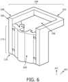
- the oral irrigator has a handle 108, 300 which has a housing 112, 304 encasing a cavity 116, 306 in which a pause control assembly 120 is contained.
- FIG. 3 is an illustration of pause control assembly 120, in an exploded view.
- FIG. 4 is a compressed view of the components of the pause control assembly 120.
- the pause control assembly 120 contains a valve assembly 124 which has a valve body 128 where the valve body 128 has a first end 132 and a second end 136.
- the valve body 128 also has a valve 140 positioned between the first end 132 of the valve body 128 and the second end 136 of the valve body 128.
- FIG. 5 is a schematic illustration of the interior of the valve body 128.
- the interior of the valve body 128 contains a fluid channel 144 through which fluid flow 148 can move, in a first direction dr1, from the first end 132 of the valve body to the second end 136 of the valve body, when the oral irrigator 104 (shown in FIG. 2 ) is in an on state S1.
- the valve 140 blocks the fluid channel 144 and blocks fluid flow 148 through the fluid channel 144 to the nozzle 109 (shown in FIG. 1 ) when the valve 140 is closed.
- the valve 140 can be arranged to completely block fluid flow 148 when the valve is completely closed and partially block fluid flow 148 when the valve 140 is partially closed.
- the pause control assembly 120 also has a slider 152, positioned outside the valve body 128, having a first end 154 and a second end 158, and a first protrusion 164 on the first end 154.
- the first protrusion 164 extends in the second direction dr2.
- the slider 152 also has a user contact 162 which is a protrusion on a surface 163 of the slider facing away from the valve body 128.
- the user contact 162 is designed to be accessible to the user of the oral irrigator 104 from the exterior of the housing 112.
- the user contact 162 can be a button, a slider, a protrusion, or any contact which can be shifted from one position to another position to shift the slider from a first position 156 to a second position 160 and/or from a second position 160 to a first position 156 (shown in FIG. 14 and FIG. 15 ).
- the pause control assembly 120 further includes a return 168 which is positioned between the valve body 128 and the slider 152.
- the first portion 172 of the return 168 extends in a first direction dr1
- the second portion 184 of the return 168 extends in a second direction, dr2, orthogonal to the first direction dr1.
- the first portion 172 has a first end 176 and a second end 180, on opposite ends of the first portion 172.
- the second portion 184 has a third end 188 and a fourth end 192, on opposite ends of the second portion 184.
- the second end 180 of the return 168 and the third end 188 of the return 168 are connected with each other and can be integrally connected to create one unit. As shown in FIG.
- the first protrusion 164 of the slider 152 makes contact with the first end 176 of the return 168.
- the second portion 184 of the return 168 has through bore 196, through which the valve body 128 is positioned, between the third end 188 and the fourth end 192 of the return 168.
- the pause control assembly 120 further includes a stopper 208 which is positioned outside the valve body 128 and opposite to the return 168 and slider 152.
- the valve body 128 also includes a resilient device 220, which is positioned on the exterior of the valve body 128 between the first end 132 and the second end 136 of the valve body 128.
- the resilient device 220 is positioned such that it makes contact with the return 168 on one end and makes contact with the valve body 128 on the opposite end.
- the resilient device 220 can be a spring, or the resilient device 220 can be any device capable of storing and releasing potential energy, or compressing and expanding, in response to the motion of the return 168.
- the pause control assembly 120 further includes a hinge 224 having a first hinge component 228 and a second hinge component 232.
- the first hinge component 228 is positioned on the valve body 128 between the first end 132 and the second end 136 of the valve body 128.
- the first hinge component 228 is fastened to the valve body 128 and oriented such that it can work in connection with the second hinge component 232 which is located on the stopper 208.
- the valve body 128 also includes a second biasing element 244 secured to the valve body 128 between the first end 132 and the second end 136.
- the second biasing element 244 is positioned such that it can make contact with the stopper 208.
- the second biasing element 244 can be a spring or any flexible material capable of storing and releasing potential energy.
- the second biasing element 244 is positioned such that it can apply a force 246 substantially in the second direction dr2.
- the stopper 208 further comprises a first portion 236 which extends in the first direction dr1 from the second hinge component 232, and a second portion 240 which extends in the third direction dr3, opposite the first direction, from the second hinge component 232.
- the first portion 236 of the stopper has a catch 248 and a ledge 252 on the end of the first portion 236 opposite the end of the first portion 236 which has hinge component 232.
- the catch 248 extends in the first direction dr1 and has a first surface 250 which extends along the first direction dr1 and faces the second direction dr2.
- the ledge 252 extends in the second direction dr2 and has a first surface 254 which extends along the second direction dr2 and has a surface which faces the first direction dr1.
- the first surface 254 of the ledge 252 does not extend in the second direction dr2 beyond the first portion 236 of the stopper 208.
- the first surface 250 of the catch 248 and the first surface 254 of the ledge 252 are positioned such that they are adjacent and perpendicular to each other and create a cavity in the space opposite and between the first surface 250 and first surface 254.
- FIG. 9 is a schematic representation of the components of the pause control assembly 120.
- the slider 152 is in the second position 160 (which corresponds to an open valve 140). Adjacent to the slider 152 in the second direction dr2 is the return 168.
- the return 168 is also in its second position 204.
- the first protrusion 164 of the slider 152 makes contact with the first end 176 of the return 168.
- the valve body 128 is received in the through bore 196 (not shown) of the return 168 between the third end 188 and the fourth end 192 of the return 168.
- the stopper 208 is in its second and closed position 216.
- the stopper 208 is arranged such that catch 248 and the ledge 252 positioned on the first portion 236 of the stopper 208 receive the fourth end 192 of the return 168.
- the catch 248 applies a force on the return 168 in the second direction dr2.
- the ledge 252 of the stopper 208 applies a force on the return 168 in the first direction dr1 and prevents the return 168 from moving in the third direction dr3.
- the return 168 is in the locked state.
- the stopper rotates in the first rotational direction RD1 about the hinge 224. This compresses the second biasing element 244, 232 which applies a force against the stopper 208 in the second direction dr2. As the fourth end of the return 192 moves in the first direction dr1, it falls into the cavity created by the catch 248 and ledge 252 of the stopper.
- the force against the stopper 208 in the second direction dr2 from the second biasing element 244 and the force applied by the catch 248 in the second direction dr2 prevent the stopper from rotating further in the first rotational direction rd1 and the through bore 196 of the return 168 from extending past the ledge 252 of the stopper 208.
- the return is prevented from moving in the third direction dr3 opposite the first direction dr1.
- the oral irrigator system 100 further includes a stand 264 which is arranged to receive the oral irrigator handle 108.
- the stand 264 is shaped to have an exterior where the oral irrigator handle 108 can be placed in a fixed and regular position.
- the stand 264 includes a magnet 268 arranged in or on the stand 264 such that it is proximate to the pause control assembly 120 located inside the housing 112 of the oral irrigator handle 108.
- the magnet 268 is arranged to apply a force Fma, towards the magnet 268, on the second portion 240 of the stopper 208 of the pause control assembly 120 and in the second direction dr2 away from the valve body 128 of the pause control assembly 120 located in the housing 112.
- the stand 264 includes a mechanical protrusion 272 positioned on the exterior of the stand 264 and arranged such that it can make contact with the oral irrigator handle 108.
- the mechanical protrusion 272 makes contact with the stopper 208 of the pause control assembly 120 through a through bore 114 of the housing 112 and through a through bore 242 of the second portion 240 of the stopper 208 such that the mechanical protrusion applies a force Fme on the stopper 208 in the second direction dr2 away from the valve body 128 of the pause control assembly 120 and towards the stand 264.
- FIG. 14 provides a schematic representation of parts of the pause control assembly 120.
- the slider 152 is in contact with the valve 140 using a toothed contact 276 (see also FIG. 3 ) on the slider 152 and the valve 140, so that the valve 140 can move and be opened and closed when the slider 152 moves.
- the slider 152 and return 168 are also connected with each other, so that when the slider 152 moves along the first direction dr1, the return 168 can move along with the slider 152. As shown in FIG. 3 , FIG. 4 , and FIG.
- the first protrusion 164 of the slider 152 makes contact with the first end 176 of the return 168, so that when the slider 152 moves in the first direction dr1 from its first position 172 to its second position 176 (as shown in FIG. 15 ), the slider 152 moves the return 168 in the first direction dr1.
- the slider 152 moves in the third direction dr3
- the slider 152 does not move the return 168 along in the third direction dr3.
- the contact between the first protrusion 164 of the slider 152 and the first end 176 of the return 168 does not create a force in the third direction dr3 on the return 168.
- valve 140 when the slider 152 is moved from the first position 156 to the second position 160 (shown in FIG. 15 ), the valve 140 is also changed from the closed state to the open state (shown in FIG. 15 ).
- the return 168 which is in contact with the slider 152 such that it moves along with the slider 152 in the first direction dr1, also moves from its first position 200 to its second position 204 (shown in FIG. 15 ).
- valve 140 When the valve 140 is open fluid flow 148 through the fluid channel 144 moves through to the nozzle 109. As shown in FIG.
- fluid flow 148 through the fluid channel 144 can be paused by moving the slider 152 from the second position 160 to the first position 156, which shifts the valve from the open to the closed state.
- the return 168 moves from the first position 200 to the second position 204, the return 168 compresses the resilient device 220 (shown in FIG. 15 ), which now stores potential energy which can be released.
- the stopper shifts from the first and open position 212 (shown in FIG. 14 ) to the closed and second position 216.
- fluid flow 148 through the fluid channel 144 to the nozzle 109 can be resumed by moving the slider 152 from the first position 156 to the second position 160, which shifts the valve 140 from the closed to the open state.
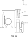
- FIG. 16 and FIG. 17 after the slider 152 moves to the second position 160, and the stopper is in the second and closed position 216, which locks the return 168, the return 168 does not move and the resilient device 220 remains in the compressed state storing potential energy.
- FIG. 17 shows how the stopper is unlocked, or moved from the closed and second position 216 to the open and first position 212.
- a force F is applied in the second direction dr2, towards the stand 264. This force moves the stopper 208 towards the stand 264 and from the closed position 216 to the open position 212.
- the return 168 is no longer prevented from moving.
- the potential energy stored in the compressed resilient device 220 is released and the resilient device 220 expands.
- the resilient device 220 which is in contact with the return 168 (as shown in FIG. 3 ), moves the return 168 from the second position 204 to the first position 200.
- the force from the resilient device 220 on the return 168 in the third direction dr3 also moves the slider 152 from the second position 160 to the first position 156, which moves the valve 140 from the open state to the closed state. If the valve 140 is already in the closed state, and the slider is in the first position 156, when the handle 108 is placed on the stand 264, the resilient device 220 applies a force on the return 168 moving it from the second position 204 to the first position 200, such that the return 168 and slider 152 are now in contact with each other where the first protrusion 164 meets the first end 176 of the slider 152.
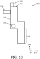
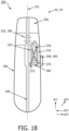
- FIG. 18 and FIG. 19 show an exemplary oral irrigator handle 300 with a pause control reset mechanism.
- the oral irrigator handle 300 contains a housing 304 with a cavity 306 which contains a fluid channel 308.
- fluid flow 312 moves in a first direction dr1 which is substantially parallel with a first axis 316.
- the oral irrigator handle 300 contains a valve 320 which is arranged to inhibit fluid flow 312 through the fluid channel 308 to the nozzle 109 when the valve 320 is closed 396 (shown in FIG.
- the cavity 306 contains a pressure plate 324 and a pressure chamber 328 (shown in FIG. 19 ) adjacent to the fluid channel 308 which are arranged to respond to a change in pressure in the fluid channel 308 due to fluid flow 312.
- the pressure plate 324 extends in the first direction dr1, and has a surface which faces the second direction dr2 or the third direction dr3, which are both orthogonal to the first direction dr1.
- a resilient device 332 Adjacent to pressure plate 324, and on the opposite side of the pressure plate 324 as the fluid channel 308, there is a resilient device 332 which is arranged to compress in the second direction dr2 or the third direction dr3 in response to fluid pressure in the fluid channel 308 which causes a first force Fp in the second direction dr2 or the third direction dr3 against the surface of the pressure plate 324. As the first force Fp is applied against the pressure plate 324 and the pressure plate 324 moves, the resilient device 332 is compressed.
- the resilient device 332 can be a spring, or any device capable of storing and releasing potential energy.
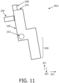
- a gated path component 336 is positioned in the cavity 306, adjacent to the pressure plate 324 and the resilient device 332 along a fourth direction dr4 which is orthogonal to the first direction dr1 and the second dr2 and third dr3 directions.
- the gated path component 336 has a body 340 with a first channel 344 and a second channel 356.
- the first channel 344 extends in the second direction dr2 or the third direction dr3, and has a first end 348 and a second end 352.
- the second channel 356 extends in first direction dr1, at a first angle 382 with respect to the first axis 316, and has a third end 360 and a fourth end 364.
- the second end 352 of the first channel 344 and the third end 360 of the second channel 356 are integrally connected with each other.
- a guide pin 372 which extends in the fourth direction dr4, is positioned between the pressure plate 324 and the resilient device 332 and in the body 340 of the gated path component 336.
- the guide pin 372 is positioned in the body 340 of the gated path component 336, and can move along first channel 344 and the second channel 356 of the gated path component 336.
- the movement of the guide pin 372 is restricted by the pressure plate 324 and the resilient device 332 as the guide pin 372 is positioned between the pressure plate 324 and the resilient device 332.
- the first position 400 of the slider 368 corresponds to the closed state 396 of the valve 320 (shown in FIG. 18 ).
- the second position 404 of the slider 368 corresponds to the open state 392 of the valve 320 which permits fluid flow 312 through the valve 320 (shown in FIG. 19 ).
- a tab 376 is located within the cavity 306 of the oral irrigator handle 300 and is fixedly secured to the slider 368.
- the tab 376 has a third channel 380, which extends in the second direction dr2 or third direction dr3, and the guide pin 372 is arranged so that it can slide along the third channel 380.
- the guide pin 372 is positioned between the pressure plate 324 and the resilient device 332 and also experiences Fp.
- the guide pin 372 is arranged to move along the third channel 380 of the tab and the first channel 344 and second channel 356 of the gated path component 336.
- the third channel 380 of the tab 376 and the first channel 344 of the gated path component 336 are aligned so that the guide pin 372 can move along the third channel 380 in the second or third directions dr2 or dr3, and can move along the first channel 344 of the gated path component 336, from the first end 348 to the second end 352 (see FIG. 18 and FIG. 20 ).
- the pressure plate 324 moves away from the fluid channel 308, and the guide pin 372 can move along the third channel 380 in the second or third directions dr2 or dr3, and can move along the first channel 344 of the gated path component 336, from the first end 348 to the second end 352.
- the guide pin 372 can move along the second channel 356 of the gated path component 336. This (guide pin 372 being able to move along the second channel 356) corresponds to an unlocked state S3.
- the slider 368 is connected to the guide pin 372 by the tab 376, only once the guide pin 372 reaches the second channel 356 of the gated path component 336 can the slider 368 be moved from the first position 400 ( FIG. 18 ) to the second position 404 ( FIG. 19 ), along the first direction dr1. Therefore, the slider can only be moved to the second position 404 corresponding to the open state of the valve 392, when the power of the oral irrigator is on S1, and after the first force Fp moves the guide pin 372 to the second channel 356 of the gated path component 336.
- the guide pin 372 moves along the second channel 356 of the gated path component 336 from the third end 360 to the fourth end 364.
- the slider 368 can be moved by the user between the first position 400 and the second position 404 and back to the first position 400, pausing and unpausing the flow of fluid to the nozzle 109 (see FIG. 19 and FIG. 20 ).
- the second channel 356 is positioned at a first angle 382 with respect to a first axis 316, and as the guide pin 372 moves along the second or third directions dr2 or dr3 towards the fluid channel 308, the guide pin 372 also moves in the direction opposite to the first direction because of the angled orientation of the second channel 356.
- the force Fs of the expanding resilient device 332 moves the guide pin 372 along the second channel 356 of the gated path component 336 to the first channel 344.
- the guide pin 372 is connected to the tab 376 which is connected to the slider 368, and the slider 368 moves from the second position 404 to the first position 400 (corresponding to a closed valve 396).
- the guide pin 372 can move along the second or third direction dr2 or dr3 towards the fluid channel 308 along the third channel 380 of the tab 376 and along the first channel 344 of the gated path component 336, from the second end 352 to the first end 348.
- the guide pin 372 is positioned between the pressure plate 324 and the resilient device 332 so that as the resilient device 332 expands and moves the guide pin 372, the pressure plate 324 also moves towards the fluid channel 308.
- the resilient device 332 has expanded and the guide pin 372 is located at the first end 348 of the gated path component, this corresponds to the locked state S4 (shown in FIG. 18 ).
- the slider 368 cannot be moved to the second position 404 corresponding to an open valve 392 until a first force Fp builds up in the fluid channel 308 due to fluid flow 312 when the oral irrigator is powered on.
- the phrase "at least one,” in reference to a list of one or more elements, should be understood to mean at least one element selected from any one or more of the elements in the list of elements, but not necessarily including at least one of each and every element specifically listed within the list of elements and not excluding any combinations of elements in the list of elements.
- This definition also allows that elements may optionally be present other than the elements specifically identified within the list of elements to which the phrase "at least one" refers, whether related or unrelated to those elements specifically identified.
Landscapes
- Health & Medical Sciences (AREA)
- Epidemiology (AREA)
- Life Sciences & Earth Sciences (AREA)
- Animal Behavior & Ethology (AREA)
- General Health & Medical Sciences (AREA)
- Public Health (AREA)
- Veterinary Medicine (AREA)
- Dentistry (AREA)
- Pain & Pain Management (AREA)
- Physical Education & Sports Medicine (AREA)
- Rehabilitation Therapy (AREA)
- Infusion, Injection, And Reservoir Apparatuses (AREA)
Claims (11)
- Procédé de réinitialisation d'un mécanisme de commande de pause d'un irrigateur buccal, le procédé (10) comprenant :la fourniture (20) de l'irrigateur buccal, l'irrigateur buccal comprenant un manche présentant un élément de commande de pause bistable ;le placement (30) de l'irrigateur buccal dans un état de marche pour permettre un écoulement de fluide à travers un canal fluidique du manche de l'irrigateur buccal ;l'actionnement (40) d'une soupape (140), via l'élément de commande de pause bistable, pour permettre l'écoulement de fluide à travers une soupape du manche de l'irrigateur buccal, comprimant (50) ainsi un dispositif élastique d'une première position à une seconde position ;le verrouillage (60), via un mécanisme de verrouillage, du dispositif élastique dans la seconde position ;la libération (70) du mécanisme de verrouillage en plaçant le manche de l'irrigateur buccal sur un support ou en commutant l'irrigateur buccal dans un état éteint de telle sorte que le dispositif élastique (220, 232) se dilate de la seconde position à la première position, réglant ainsi l'élément de commande de pause pour empêcher l'écoulement de fluide à travers la soupape (140).
- Système (100) d'irrigateur buccal comprenant un irrigateur buccal (104) comprenant un manche (108) d'irrigateur buccal comprenant un boîtier (112), le boîtier présentant une cavité (116) agencée à l'intérieur de celui-ci, la cavité comprenant un ensemble de commande de pause (120) comprenant :un corps (128) de soupape présentant une soupape (140) ;un coulisseau (152) couplé à la soupape (140), dans lequel le coulisseau est configuré pour se déplacer entre une première position (156) et une seconde position (160), le coulisseau comprenant en outre une première saillie (164) ;un retour (168) comprenant :une première partie (172) s'étendant dans une première direction (dr1), la première partie présentant une première extrémité (176) et une deuxième extrémité (180), dans lequel la première extrémité est en contact avec la première saillie du coulisseau ; etune seconde partie (184) s'étendant dans la deuxième direction (dr2) perpendiculaire à la première direction (dr1), la seconde partie présentant une troisième extrémité (188) et une quatrième extrémité (192), dans lequel la seconde partie comprend en outre un alésage traversant (196) agencé pour recevoir le corps (128) de soupape ;dans lequel la deuxième extrémité (180) de la première partie (172) et la troisième extrémité (188) de la seconde partie (184) sont reliées l'une à l'autre ;dans lequel lorsque le coulisseau (152) est déplacé de la première position (156) à la seconde position (160), le retour (168) est déplacé dans la première direction (dr1) d'une première position (200) à une seconde position (204) ;un dispositif d'arrêt (208), présentant une position ouverte (212) et une position fermée (216), dans lequel le dispositif d'arrêt (208) est agencé pour empêcher le mouvement de retour (168) dans une troisième direction (dr3) opposée à la première direction (dr1) de sa seconde position (204) à sa première position (200),dans lequel l'ensemble de commande de pause (120) est configuré de telle sorte que la première position (156) du coulisseau (152) corresponde à un état fermé de la soupape (140) et la seconde position (160) du coulisseau (152) corresponde à un état ouvert de la soupape (140), dans lequel lorsque le retour est déplacé vers sa seconde position (204), le dispositif d'arrêt (208) est venir en prise avec et fixer la quatrième extrémité (192) du retour.
- Manche d'irrigateur buccal selon la revendication 2, dans lequel l'ensemble de commande de pause (120) comprend en outre un dispositif élastique (220) agencé pour solliciter le retour (168) dans une troisième direction opposée à la première direction.
- Manche d'irrigateur buccal selon la revendication 2, dans lequel l'ensemble de commande de pause (120) comprend en outre une charnière (224), la charnière comprenant :un premier composant de charnière (228) agencé sur le corps (128) de soupape ; etun second composant de charnière (232) agencé sur le dispositif d'arrêt (208) ;dans lequel la charnière est configurée pour permettre au dispositif d'arrêt de tourner dans un premier sens de rotation et un second sens de rotation opposé au premier sens de rotation.
- Manche d'irrigateur buccal selon la revendication 4, dans lequel le dispositif d'arrêt (208) comprend en outre une première partie (236) s'étendant dans la première direction à partir du second composant de charnière (232) et une seconde partie (240) s'étendant dans la troisième direction à partir du second composant de charnière.
- Manche d'irrigateur buccal selon la revendication 5, comprenant en outre un corps (128) de soupape présentant un élément de précontrainte (244) agencé pour solliciter la première partie (236) du dispositif d'arrêt dans la deuxième direction ; etdans lequel lorsque le retour (168) est dans la seconde position (204), le dispositif d'arrêt est agencé pour tourner dans le premier sens de rotation autour de la charnière (224) et venir en prise avec et fixer la quatrième extrémité (192) du retour dans un état verrouillé ; etdans lequel la première partie du dispositif d'arrêt (208) comprend en outre un loquet (248) faisant saillie dans la première direction et un rebord (252) faisant saillie dans la deuxième direction, dans lequel le rebord est agencé pour appliquer une force dans la première direction et le loquet est agencé pour appliquer une force dans la deuxième direction lorsque le dispositif d'arrêt est dans la seconde position (216) lorsque le retour est dans un état verrouillé.
- Manche d'irrigateur buccal selon la revendication 2, comprenant en outre un support (264) agencé pour recevoir le manche d'irrigateur buccal et agencé pour venir en prise avec le dispositif d'arrêt (208).
- Manche d'irrigateur buccal selon la revendication 7, dans lequel le support (264) comprend un aimant (268) agencé pour solliciter la seconde partie du dispositif d'arrêt (240) ; ou,
le support comprend une saillie mécanique (272) agencée pour venir en prise avec la seconde partie du dispositif d'arrêt. - Système (100) d'irrigateur buccal présentant un irrigateur buccal (104) avec un manche (300), le manche comprenant un boîtier (304), le boîtier présentant une cavité (306) agencée à l'intérieur de celui-ci, la cavité comprenant :un canal fluidique (308) dans lequel un écoulement de fluide (312) se déplace dans une première direction (dr1) sensiblement parallèle à un premier axe (316) lorsque l'irrigateur buccal est en état de marche ;une soupape (320) agencée pour empêcher et permettre l'écoulement de fluide à travers le canal fluidique lorsqu'elle est dans un état fermé et dans un état ouvert, respectivement ;une plaque de pression (324) agencée pour subir une force (Fp), qui déplace la plaque de pression dans une deuxième direction (dr2) perpendiculaire à la première direction (dr1) lorsque la pression augmente dans le canal fluidique en raison de l'écoulement de fluide, ceci pour faire passer l'irrigateur buccal à un état déverrouillé ;un dispositif élastique (332) agencé pour se comprimer dans la deuxième direction (dr2) lorsque la plaque de pression se déplace ;un composant de circuit régulé (336), présentant un corps (340), le corps comprenant :un premier canal (344) agencé à l'intérieur du corps et s'étendant dans la deuxième direction (dr2), le premier canal présentant une première extrémité (348) et une deuxième extrémité (352) ;un deuxième canal (356) agencé à l'intérieur du corps s'étendant dans une direction selon un premier angle (382) par rapport au premier axe (316), le deuxième canal (356) présentant une troisième extrémité (360) et une quatrième extrémité (364) ;dans lequel la deuxième extrémité (352) du premier canal (344) et la troisième extrémité (360) du deuxième canal (356) sont intégralement reliées l'une à l'autre ;dans lequel le manche comprend en outre :un coulisseau (368) agencé pour se déplacer d'une première position (400) à une seconde position (404), dans lequel la première position et la seconde position correspondent à l'état fermé et à l'état ouvert de la soupape (320), respectivement,une broche de guidage (372) agencée à l'intérieur de la cavité (306) du manche d'irrigateur buccal, la broche de guidage étant agencée pour se déplacer à l'intérieur du premier canal (344) et du deuxième canal (356) du composant de circuit régulé (336), etune languette (376) fixée à demeure au coulisseau, la languette comprenant un troisième canal (380) s'étendant dans la deuxième direction (dr2), dans lequel la broche de guidage (372) est agencée pour pouvoir coulisser le long du troisième canal (380), et dans lequel le troisième canal (380) est agencé pour engager de manière coulissante la broche de guidage (372), dans lequel le coulisseau (368) est relié à la broche de guidage (372) par la languette (376) ;dans lequel la broche de guidage (372) est positionnée entre la plaque de pression (324) et le dispositif élastique (332), de telle sorte que la force (Fp) soit en outre appliquée à la broche de guidage (372) en réponse à l'augmentation de pression dans le canal fluidique (308) en raison de l'écoulement de fluide, et dans lequel la broche de guidage (372) est agencée pour se déplacer le long du troisième canal (380) et du premier canal (344) dans la deuxième direction (dr2) en réponse à l'application d'une force (Fp),dans lequel, une fois que la broche de guidage (372) atteint la deuxième extrémité (352) du premier canal (344) du composant de circuit régulé (336), la broche de guidage (372) est mobile le long du deuxième canal (356) du composant de circuit régulé (336), ceci correspondant à l'état déverrouillé (S3) ;dans lequel, dans l'état déverrouillé, le coulisseau (368) est mobile de la première position (400) à la seconde position (404), et dans lequel le mouvement du coulisseau déplace la broche de guidage (372) le long du deuxième canal (356), du composant, composant de circuit régulé (336), et dans lequel le passage du coulisseau (368) de la première position à la seconde position correspond à un passage de la soupape (320) de l'état fermé à l'état ouvert.
- Système d'irrigateur buccal selon la revendication 9, dans lequel lorsque l'irrigateur buccal (104) est à l'état éteint, le coulisseau (368) est agencé pour se déplacer de la seconde position (404) à la première position (400), et le coulisseau (368) est agencé pour déplacer la broche de guidage (372) le long du deuxième canal (356) du composant de circuit régulé (336), dans lequel le passage du coulisseau (368) de la seconde position (404) à la première position (400) correspond à un passage de la soupape (320) de l'état ouvert à l'état fermé.
- Système d'irrigateur buccal selon la revendication 9, dans lequel, à l'état éteint, la broche de guidage (372) est en outre agencée pour se déplacer à l'intérieur du premier canal (344) du composant de circuit régulé (336) de la deuxième extrémité (352) à la première extrémité (348), passant dans un état verrouillé.
Applications Claiming Priority (2)
| Application Number | Priority Date | Filing Date | Title |
|---|---|---|---|
| US201962835609P | 2019-04-18 | 2019-04-18 | |
| PCT/EP2020/060653 WO2020212465A1 (fr) | 2019-04-18 | 2020-04-16 | Mécanisme de réinitialisation automatique d'une commande de pause |
Publications (3)
| Publication Number | Publication Date |
|---|---|
| EP3955852A1 EP3955852A1 (fr) | 2022-02-23 |
| EP3955852B1 true EP3955852B1 (fr) | 2024-07-31 |
| EP3955852C0 EP3955852C0 (fr) | 2024-07-31 |
Family
ID=70295126
Family Applications (1)
| Application Number | Title | Priority Date | Filing Date |
|---|---|---|---|
| EP20720001.5A Active EP3955852B1 (fr) | 2019-04-18 | 2020-04-16 | Mécanisme de réinitialisation automatique d'une commande de pause |
Country Status (5)
| Country | Link |
|---|---|
| US (1) | US12508112B2 (fr) |
| EP (1) | EP3955852B1 (fr) |
| JP (1) | JP7507787B2 (fr) |
| CN (1) | CN113692260B (fr) |
| WO (1) | WO2020212465A1 (fr) |
Families Citing this family (1)
| Publication number | Priority date | Publication date | Assignee | Title |
|---|---|---|---|---|
| CN120475943A (zh) * | 2023-01-10 | 2025-08-12 | 洁碧有限公司 | 用于口腔冲洗器的阀组件 |
Family Cites Families (25)
| Publication number | Priority date | Publication date | Assignee | Title |
|---|---|---|---|---|
| DE3101941A1 (de) | 1981-01-22 | 1982-08-19 | Gimelli & Co. AG, 3052 Zollikofen | Handstueck fuer ein mund- und zahnspritzgeraet |
| DE3208666A1 (de) * | 1982-03-10 | 1983-09-22 | Siemens AG, 1000 Berlin und 8000 München | Zahnaerztliches spritzhandstueck |
| DE3225918A1 (de) | 1982-07-10 | 1984-01-12 | Gimelli & Co. AG, 3052 Zollikofen | Steckvorrichtung an einem handgeraet zur koerperpflege, insbesondere zahn- und mundpflege |
| DE3231537A1 (de) | 1982-08-25 | 1984-03-01 | Gimelli & Co. AG, 3052 Zollikofen | Handstueck fuer ein mund- und zahnspritzgeraet |
| DE59507414D1 (de) * | 1994-06-22 | 2000-01-20 | Koninkl Philips Electronics Nv | Zahnreinigungseinrichtung mit einem Handstück |
| US6382970B1 (en) | 2001-01-19 | 2002-05-07 | Stephen A. Foster | Dental air/water syringe purge device |
| CN1262251C (zh) * | 2002-09-04 | 2006-07-05 | 瑞科有限公司 | 自给式口腔清洁装置 |
| JP2006158938A (ja) | 2004-11-10 | 2006-06-22 | Eishin Sangyo Kk | 口腔洗浄具取付水栓及び脱着口腔洗浄具 |
| CN202569196U (zh) * | 2012-02-28 | 2012-12-05 | 桂林市啄木鸟医疗器械有限公司 | 单通流量调节开关 |
| JP5924415B2 (ja) | 2012-11-08 | 2016-05-25 | サンスター株式会社 | 口腔洗浄装置 |
| ES2718685T3 (es) | 2013-11-27 | 2019-07-03 | Water Pik Inc | Irrigador bucal con interruptor de pausa deslizante |
| CN203749627U (zh) * | 2014-01-06 | 2014-08-06 | 洁碧有限公司 | 手持式口腔冲洗器 |
| CN203953860U (zh) * | 2014-01-06 | 2014-11-26 | 洁碧有限公司 | 口腔卫生装置 |
| RU2709137C2 (ru) | 2015-02-05 | 2019-12-16 | Конинклейке Филипс Н.В. | Стыковочно-зарядная станция и операция заполнения для ручного устройства для очистки полости рта |
| DE102015103291A1 (de) * | 2015-03-06 | 2016-09-08 | Ferton Holding S.A. | Pulverstrahlgerät |
| KR102072661B1 (ko) * | 2016-01-25 | 2020-02-03 | 워터 피크 인코포레이티드 | 형상 인자가 감소된 구강 세정기 |
| CN107874857B (zh) * | 2016-09-29 | 2024-07-19 | 周星 | 可视牙齿冲洗器 |
| EP3554420B1 (fr) | 2016-12-15 | 2021-05-19 | Water Pik, Inc. | Ensembles pivot et clapet de pause pour manche d'irrigateur buccal |
| KR102576326B1 (ko) * | 2016-12-15 | 2023-09-08 | 워어터 피이크, 인코포레이티드 | 자기 부착부를 갖는 구강 세척기 |
| CN207186871U (zh) * | 2017-03-10 | 2018-04-06 | 李继武 | 一种医用臭氧三用冲洗装置 |
| AU2018236429B2 (en) * | 2017-03-16 | 2023-02-02 | Water Pik, Inc. | Oral irrigator handle for use with oral agent |
| WO2018193798A1 (fr) | 2017-04-21 | 2018-10-25 | 株式会社エーゼット | Appareil de traitement dentaire |
| CN107212939A (zh) * | 2017-06-09 | 2017-09-29 | 九牧厨卫股份有限公司 | 一种洗牙龙头 |
| CN108223842B (zh) * | 2018-02-07 | 2023-11-14 | 九牧厨卫股份有限公司 | 一种可以冲牙的出水装置和抽拉式水龙头 |
| KR102059499B1 (ko) * | 2018-03-19 | 2020-02-11 | 주식회사 아폴로니아 | 치과용 기구 오염방지유닛, 이를 구비한 치과용 시술기구 및 세척액 공급장치 |
-
2020
- 2020-04-16 EP EP20720001.5A patent/EP3955852B1/fr active Active
- 2020-04-16 US US17/604,399 patent/US12508112B2/en active Active
- 2020-04-16 JP JP2021561672A patent/JP7507787B2/ja active Active
- 2020-04-16 CN CN202080029282.1A patent/CN113692260B/zh active Active
- 2020-04-16 WO PCT/EP2020/060653 patent/WO2020212465A1/fr not_active Ceased
Also Published As
| Publication number | Publication date |
|---|---|
| WO2020212465A1 (fr) | 2020-10-22 |
| CN113692260A (zh) | 2021-11-23 |
| EP3955852A1 (fr) | 2022-02-23 |
| JP7507787B2 (ja) | 2024-06-28 |
| US20220211474A1 (en) | 2022-07-07 |
| CN113692260B (zh) | 2025-01-14 |
| US12508112B2 (en) | 2025-12-30 |
| EP3955852C0 (fr) | 2024-07-31 |
| JP2022529014A (ja) | 2022-06-16 |
Similar Documents
| Publication | Publication Date | Title |
|---|---|---|
| EP3287722B1 (fr) | Armoire pour véhicule de loisirs | |
| KR940021871A (ko) | 인출회전형 문용 록핸들 장치 | |
| EP3955852B1 (fr) | Mécanisme de réinitialisation automatique d'une commande de pause | |
| KR20100129753A (ko) | 캠락 | |
| JP2004500201A5 (fr) | ||
| GB2451663A (en) | Injection device with coupled cap and needle shield | |
| RU95113092A (ru) | Кассета для закапывания лекарственного средства в глаз | |
| KR20110069746A (ko) | 가구부재 서랍용 또는 가동부용 자동폐쇄장치 | |
| KR940021872A (ko) | 인출회전형 문용 록핸들장치 | |
| US20170110266A1 (en) | Safety lock mechanism for trigger switch handle of miter saw | |
| EP3275807A1 (fr) | Dispositif pour couvercle rotatif de poubelle | |
| US12139937B2 (en) | Latching assembly | |
| KR101330441B1 (ko) | 사물함용 잠금장치 | |
| US7442182B2 (en) | Spring powered needle-free injection system | |
| FI88249C (fi) | Anordning foer foerhindrande av oavsiktliga startroerelser i aotminstone en omkring en axel svaengbar yta, saosom ryggstoed pao stolar, skaophaelfter m.m. | |
| KR20140122347A (ko) | 사물함용 잠금장치 | |
| CN112292504B (zh) | 用于打开和关闭被支承的盖的装置 | |
| CN207813316U (zh) | 锁紧装置及冰箱 | |
| CN111245997B (zh) | 电子装置基座 | |
| US20260077517A1 (en) | Retractable Pocket Clip for Knife | |
| KR100415053B1 (ko) | 도어록 장치 | |
| SU1725761A3 (ru) | Запирающий механизм замка | |
| KR910003460Y1 (ko) | 콘트롤 스위치보드의 도아(door)개폐장치 | |
| CN119141598A (zh) | 一种折叠刀锁定结构 | |
| US9206635B1 (en) | Door closing device |
Legal Events
| Date | Code | Title | Description |
|---|---|---|---|
| STAA | Information on the status of an ep patent application or granted ep patent |
Free format text: STATUS: UNKNOWN |
|
| STAA | Information on the status of an ep patent application or granted ep patent |
Free format text: STATUS: THE INTERNATIONAL PUBLICATION HAS BEEN MADE |
|
| PUAI | Public reference made under article 153(3) epc to a published international application that has entered the european phase |
Free format text: ORIGINAL CODE: 0009012 |
|
| STAA | Information on the status of an ep patent application or granted ep patent |
Free format text: STATUS: REQUEST FOR EXAMINATION WAS MADE |
|
| 17P | Request for examination filed |
Effective date: 20211118 |
|
| AK | Designated contracting states |
Kind code of ref document: A1 Designated state(s): AL AT BE BG CH CY CZ DE DK EE ES FI FR GB GR HR HU IE IS IT LI LT LU LV MC MK MT NL NO PL PT RO RS SE SI SK SM TR |
|
| DAV | Request for validation of the european patent (deleted) | ||
| DAX | Request for extension of the european patent (deleted) | ||
| STAA | Information on the status of an ep patent application or granted ep patent |
Free format text: STATUS: EXAMINATION IS IN PROGRESS |
|
| 17Q | First examination report despatched |
Effective date: 20230328 |
|
| GRAP | Despatch of communication of intention to grant a patent |
Free format text: ORIGINAL CODE: EPIDOSNIGR1 |
|
| STAA | Information on the status of an ep patent application or granted ep patent |
Free format text: STATUS: GRANT OF PATENT IS INTENDED |
|
| INTG | Intention to grant announced |
Effective date: 20240313 |
|
| GRAS | Grant fee paid |
Free format text: ORIGINAL CODE: EPIDOSNIGR3 |
|
| GRAA | (expected) grant |
Free format text: ORIGINAL CODE: 0009210 |
|
| STAA | Information on the status of an ep patent application or granted ep patent |
Free format text: STATUS: THE PATENT HAS BEEN GRANTED |
|
| AK | Designated contracting states |
Kind code of ref document: B1 Designated state(s): AL AT BE BG CH CY CZ DE DK EE ES FI FR GB GR HR HU IE IS IT LI LT LU LV MC MK MT NL NO PL PT RO RS SE SI SK SM TR |
|
| REG | Reference to a national code |
Ref country code: CH Ref legal event code: EP Ref country code: GB Ref legal event code: FG4D |
|
| REG | Reference to a national code |
Ref country code: DE Ref legal event code: R096 Ref document number: 602020034847 Country of ref document: DE |
|
| REG | Reference to a national code |
Ref country code: IE Ref legal event code: FG4D |
|
| U01 | Request for unitary effect filed |
Effective date: 20240731 |
|
| U07 | Unitary effect registered |
Designated state(s): AT BE BG DE DK EE FI FR IT LT LU LV MT NL PT SE SI Effective date: 20240808 |
|
| PG25 | Lapsed in a contracting state [announced via postgrant information from national office to epo] |
Ref country code: NO Free format text: LAPSE BECAUSE OF FAILURE TO SUBMIT A TRANSLATION OF THE DESCRIPTION OR TO PAY THE FEE WITHIN THE PRESCRIBED TIME-LIMIT Effective date: 20241031 |
|
| PG25 | Lapsed in a contracting state [announced via postgrant information from national office to epo] |
Ref country code: PL Free format text: LAPSE BECAUSE OF FAILURE TO SUBMIT A TRANSLATION OF THE DESCRIPTION OR TO PAY THE FEE WITHIN THE PRESCRIBED TIME-LIMIT Effective date: 20240731 Ref country code: GR Free format text: LAPSE BECAUSE OF FAILURE TO SUBMIT A TRANSLATION OF THE DESCRIPTION OR TO PAY THE FEE WITHIN THE PRESCRIBED TIME-LIMIT Effective date: 20241101 |
|
| PG25 | Lapsed in a contracting state [announced via postgrant information from national office to epo] |
Ref country code: IS Free format text: LAPSE BECAUSE OF FAILURE TO SUBMIT A TRANSLATION OF THE DESCRIPTION OR TO PAY THE FEE WITHIN THE PRESCRIBED TIME-LIMIT Effective date: 20241130 |
|
| PG25 | Lapsed in a contracting state [announced via postgrant information from national office to epo] |
Ref country code: HR Free format text: LAPSE BECAUSE OF FAILURE TO SUBMIT A TRANSLATION OF THE DESCRIPTION OR TO PAY THE FEE WITHIN THE PRESCRIBED TIME-LIMIT Effective date: 20240731 |
|
| PG25 | Lapsed in a contracting state [announced via postgrant information from national office to epo] |
Ref country code: RS Free format text: LAPSE BECAUSE OF FAILURE TO SUBMIT A TRANSLATION OF THE DESCRIPTION OR TO PAY THE FEE WITHIN THE PRESCRIBED TIME-LIMIT Effective date: 20241031 Ref country code: ES Free format text: LAPSE BECAUSE OF FAILURE TO SUBMIT A TRANSLATION OF THE DESCRIPTION OR TO PAY THE FEE WITHIN THE PRESCRIBED TIME-LIMIT Effective date: 20240731 |
|
| PG25 | Lapsed in a contracting state [announced via postgrant information from national office to epo] |
Ref country code: RS Free format text: LAPSE BECAUSE OF FAILURE TO SUBMIT A TRANSLATION OF THE DESCRIPTION OR TO PAY THE FEE WITHIN THE PRESCRIBED TIME-LIMIT Effective date: 20241031 Ref country code: PL Free format text: LAPSE BECAUSE OF FAILURE TO SUBMIT A TRANSLATION OF THE DESCRIPTION OR TO PAY THE FEE WITHIN THE PRESCRIBED TIME-LIMIT Effective date: 20240731 Ref country code: NO Free format text: LAPSE BECAUSE OF FAILURE TO SUBMIT A TRANSLATION OF THE DESCRIPTION OR TO PAY THE FEE WITHIN THE PRESCRIBED TIME-LIMIT Effective date: 20241031 Ref country code: IS Free format text: LAPSE BECAUSE OF FAILURE TO SUBMIT A TRANSLATION OF THE DESCRIPTION OR TO PAY THE FEE WITHIN THE PRESCRIBED TIME-LIMIT Effective date: 20241130 Ref country code: HR Free format text: LAPSE BECAUSE OF FAILURE TO SUBMIT A TRANSLATION OF THE DESCRIPTION OR TO PAY THE FEE WITHIN THE PRESCRIBED TIME-LIMIT Effective date: 20240731 Ref country code: GR Free format text: LAPSE BECAUSE OF FAILURE TO SUBMIT A TRANSLATION OF THE DESCRIPTION OR TO PAY THE FEE WITHIN THE PRESCRIBED TIME-LIMIT Effective date: 20241101 Ref country code: ES Free format text: LAPSE BECAUSE OF FAILURE TO SUBMIT A TRANSLATION OF THE DESCRIPTION OR TO PAY THE FEE WITHIN THE PRESCRIBED TIME-LIMIT Effective date: 20240731 |
|
| PG25 | Lapsed in a contracting state [announced via postgrant information from national office to epo] |
Ref country code: SM Free format text: LAPSE BECAUSE OF FAILURE TO SUBMIT A TRANSLATION OF THE DESCRIPTION OR TO PAY THE FEE WITHIN THE PRESCRIBED TIME-LIMIT Effective date: 20240731 |
|
| PG25 | Lapsed in a contracting state [announced via postgrant information from national office to epo] |
Ref country code: CZ Free format text: LAPSE BECAUSE OF FAILURE TO SUBMIT A TRANSLATION OF THE DESCRIPTION OR TO PAY THE FEE WITHIN THE PRESCRIBED TIME-LIMIT Effective date: 20240731 |
|
| PG25 | Lapsed in a contracting state [announced via postgrant information from national office to epo] |
Ref country code: SK Free format text: LAPSE BECAUSE OF FAILURE TO SUBMIT A TRANSLATION OF THE DESCRIPTION OR TO PAY THE FEE WITHIN THE PRESCRIBED TIME-LIMIT Effective date: 20240731 |
|
| U20 | Renewal fee for the european patent with unitary effect paid |
Year of fee payment: 6 Effective date: 20250430 |
|
| PLBE | No opposition filed within time limit |
Free format text: ORIGINAL CODE: 0009261 |
|
| STAA | Information on the status of an ep patent application or granted ep patent |
Free format text: STATUS: NO OPPOSITION FILED WITHIN TIME LIMIT |
|
| 26N | No opposition filed |
Effective date: 20250501 |
|
| PGFP | Annual fee paid to national office [announced via postgrant information from national office to epo] |
Ref country code: GB Payment date: 20250422 Year of fee payment: 6 |
|
| REG | Reference to a national code |
Ref country code: CH Ref legal event code: H13 Free format text: ST27 STATUS EVENT CODE: U-0-0-H10-H13 (AS PROVIDED BY THE NATIONAL OFFICE) Effective date: 20251125 |
|
| PG25 | Lapsed in a contracting state [announced via postgrant information from national office to epo] |
Ref country code: MC Free format text: LAPSE BECAUSE OF FAILURE TO SUBMIT A TRANSLATION OF THE DESCRIPTION OR TO PAY THE FEE WITHIN THE PRESCRIBED TIME-LIMIT Effective date: 20240731 |
|
| PG25 | Lapsed in a contracting state [announced via postgrant information from national office to epo] |
Ref country code: CH Free format text: LAPSE BECAUSE OF NON-PAYMENT OF DUE FEES Effective date: 20250430 |
|
| PG25 | Lapsed in a contracting state [announced via postgrant information from national office to epo] |
Ref country code: IE Free format text: LAPSE BECAUSE OF NON-PAYMENT OF DUE FEES Effective date: 20250416 |
|
| PG25 | Lapsed in a contracting state [announced via postgrant information from national office to epo] |
Ref country code: RO Free format text: LAPSE BECAUSE OF FAILURE TO SUBMIT A TRANSLATION OF THE DESCRIPTION OR TO PAY THE FEE WITHIN THE PRESCRIBED TIME-LIMIT Effective date: 20240731 |