EP3956607B1 - Dispositif injecteur pour un dispositif propulseur, dispositif propulseur et aéronef et/ou astronef - Google Patents
Dispositif injecteur pour un dispositif propulseur, dispositif propulseur et aéronef et/ou astronef Download PDFInfo
- Publication number
- EP3956607B1 EP3956607B1 EP20719987.8A EP20719987A EP3956607B1 EP 3956607 B1 EP3956607 B1 EP 3956607B1 EP 20719987 A EP20719987 A EP 20719987A EP 3956607 B1 EP3956607 B1 EP 3956607B1
- Authority
- EP
- European Patent Office
- Prior art keywords
- resonator
- injection
- injector
- channel
- elements
- Prior art date
- Legal status (The legal status is an assumption and is not a legal conclusion. Google has not performed a legal analysis and makes no representation as to the accuracy of the status listed.)
- Active
Links
Images



Classifications
-
- F—MECHANICAL ENGINEERING; LIGHTING; HEATING; WEAPONS; BLASTING
- F23—COMBUSTION APPARATUS; COMBUSTION PROCESSES
- F23R—GENERATING COMBUSTION PRODUCTS OF HIGH PRESSURE OR HIGH VELOCITY, e.g. GAS-TURBINE COMBUSTION CHAMBERS
- F23R3/00—Continuous combustion chambers using liquid or gaseous fuel
- F23R3/28—Continuous combustion chambers using liquid or gaseous fuel characterised by the fuel supply
-
- F—MECHANICAL ENGINEERING; LIGHTING; HEATING; WEAPONS; BLASTING
- F02—COMBUSTION ENGINES; HOT-GAS OR COMBUSTION-PRODUCT ENGINE PLANTS
- F02K—JET-PROPULSION PLANTS
- F02K9/00—Rocket-engine plants, i.e. plants carrying both fuel and oxidant therefor; Control thereof
- F02K9/42—Rocket-engine plants, i.e. plants carrying both fuel and oxidant therefor; Control thereof using liquid or gaseous propellants
- F02K9/44—Feeding propellants
- F02K9/52—Injectors
-
- F—MECHANICAL ENGINEERING; LIGHTING; HEATING; WEAPONS; BLASTING
- F02—COMBUSTION ENGINES; HOT-GAS OR COMBUSTION-PRODUCT ENGINE PLANTS
- F02K—JET-PROPULSION PLANTS
- F02K9/00—Rocket-engine plants, i.e. plants carrying both fuel and oxidant therefor; Control thereof
- F02K9/72—Rocket-engine plants, i.e. plants carrying both fuel and oxidant therefor; Control thereof using liquid and solid propellants, i.e. hybrid rocket-engine plants
-
- F—MECHANICAL ENGINEERING; LIGHTING; HEATING; WEAPONS; BLASTING
- F23—COMBUSTION APPARATUS; COMBUSTION PROCESSES
- F23L—SUPPLYING AIR OR NON-COMBUSTIBLE LIQUIDS OR GASES TO COMBUSTION APPARATUS IN GENERAL ; VALVES OR DAMPERS SPECIALLY ADAPTED FOR CONTROLLING AIR SUPPLY OR DRAUGHT IN COMBUSTION APPARATUS; INDUCING DRAUGHT IN COMBUSTION APPARATUS; TOPS FOR CHIMNEYS OR VENTILATING SHAFTS; TERMINALS FOR FLUES
- F23L7/00—Supplying non-combustible liquids or gases, other than air, to the fire, e.g. oxygen, steam
- F23L7/007—Supplying oxygen or oxygen-enriched air
-
- F—MECHANICAL ENGINEERING; LIGHTING; HEATING; WEAPONS; BLASTING
- F05—INDEXING SCHEMES RELATING TO ENGINES OR PUMPS IN VARIOUS SUBCLASSES OF CLASSES F01-F04
- F05D—INDEXING SCHEME FOR ASPECTS RELATING TO NON-POSITIVE-DISPLACEMENT MACHINES OR ENGINES, GAS-TURBINES OR JET-PROPULSION PLANTS
- F05D2260/00—Function
- F05D2260/96—Preventing, counteracting or reducing vibration or noise
- F05D2260/963—Preventing, counteracting or reducing vibration or noise by Helmholtz resonators
-
- F—MECHANICAL ENGINEERING; LIGHTING; HEATING; WEAPONS; BLASTING
- F05—INDEXING SCHEMES RELATING TO ENGINES OR PUMPS IN VARIOUS SUBCLASSES OF CLASSES F01-F04
- F05D—INDEXING SCHEME FOR ASPECTS RELATING TO NON-POSITIVE-DISPLACEMENT MACHINES OR ENGINES, GAS-TURBINES OR JET-PROPULSION PLANTS
- F05D2260/00—Function
- F05D2260/96—Preventing, counteracting or reducing vibration or noise
- F05D2260/964—Preventing, counteracting or reducing vibration or noise counteracting thermoacoustic noise
-
- F—MECHANICAL ENGINEERING; LIGHTING; HEATING; WEAPONS; BLASTING
- F23—COMBUSTION APPARATUS; COMBUSTION PROCESSES
- F23R—GENERATING COMBUSTION PRODUCTS OF HIGH PRESSURE OR HIGH VELOCITY, e.g. GAS-TURBINE COMBUSTION CHAMBERS
- F23R2900/00—Special features of, or arrangements for continuous combustion chambers; Combustion processes therefor
- F23R2900/00014—Reducing thermo-acoustic vibrations by passive means, e.g. by Helmholtz resonators
-
- Y—GENERAL TAGGING OF NEW TECHNOLOGICAL DEVELOPMENTS; GENERAL TAGGING OF CROSS-SECTIONAL TECHNOLOGIES SPANNING OVER SEVERAL SECTIONS OF THE IPC; TECHNICAL SUBJECTS COVERED BY FORMER USPC CROSS-REFERENCE ART COLLECTIONS [XRACs] AND DIGESTS
- Y02—TECHNOLOGIES OR APPLICATIONS FOR MITIGATION OR ADAPTATION AGAINST CLIMATE CHANGE
- Y02E—REDUCTION OF GREENHOUSE GAS [GHG] EMISSIONS, RELATED TO ENERGY GENERATION, TRANSMISSION OR DISTRIBUTION
- Y02E20/00—Combustion technologies with mitigation potential
- Y02E20/34—Indirect CO2mitigation, i.e. by acting on non CO2directly related matters of the process, e.g. pre-heating or heat recovery
Definitions
- the present invention relates to an injector device for an engine device for introducing a fluidic, in particular liquid, fuel and a fluidic, in particular liquid, oxidizing agent into a combustion chamber of the engine device, which injector device defines a longitudinal axis and comprises at least one first injection element, which is designed in the form of a first fluid channel for fluidically connecting a first collection space for the fluidic oxidizing agent and the combustion chamber, and at least one second injection element, which is designed in the form of a second fluid channel for fluidically connecting a second collection space for the fluidic fuel and the combustion chamber, wherein at least one first resonator element is assigned to the at least one first injection element and/or wherein at least one second resonator element is assigned to the at least one second injection element and wherein the at least one first resonator element is tuned to a natural frequency of the assigned at least one first injection element and/or that the at least one second resonator element is tuned to a natural frequency of the assigned at least one second injection element.
- the present invention relates to an engine device, in particular for an aircraft and/or spacecraft, which engine device comprises a combustion chamber with a nozzle and an injection device arranged opposite the nozzle, wherein acoustic natural vibrations are dampened in the at least one first injection element and/or wherein acoustic natural vibrations are dampened in the at least one second injection element, wherein at least one first resonator element is assigned to the at least one first injection element and/or wherein at least one second resonator element is assigned to the at least one second injection element wherein the at least one first resonator element is tuned to a natural frequency of the associated at least one first injection element and/or wherein the at least one second resonator element is tuned to a natural frequency of the associated at least one second injection element.
- the present invention relates to an aircraft and/or spacecraft with an engine device and a fuel tank for accommodating a fluidic, in particular liquid, fuel.
- the present invention relates to a method for operating an engine device, in which method a fluidic, in particular liquid, fuel and a fluidic, in particular liquid, oxidizing agent are introduced into a combustion chamber of the engine device using an injector device, which injector device comprises at least one first injection element for fluidically connecting a first collection space for the fluidic oxidizing agent and the combustion chamber, and at least one second injection element for fluidically connecting a second collection space for the fluidic fuel and the combustion chamber.
- Engine devices of the type described at the beginning are known, for example, in the form of liquid-fuel rocket engines.
- a fuel also referred to as propellant
- an oxidizing agent also referred to as oxidizer
- Combustion chambers of such engines usually define a cylindrical volume that is limited downstream by a convergent nozzle with a sound passage in the narrowest cross-section.
- injector plates Upstream of the combustion chamber, the fuel and the oxidizing agent are injected, for example, by so-called injector plates.
- injector plates Upstream of the combustion chamber, the fuel and the oxidizing agent are injected, for example, by so-called injector plates.
- coaxial injection elements are often used, particularly with cryogenic fuels such as liquid hydrogen, which is combined with an oxidizer in the form of liquid oxygen, or with a combination of liquid methane with liquid oxygen.
- the liquid oxygen is injected centrally. injected through a tube and the fuel flows at high speed through a narrow annular gap which is formed around the tube.
- thermoacoustic combustion instabilities arise, for example, from the interaction of combustion chamber acoustics with fluctuations in the heat release rate of the flame produced during combustion. This leads to the amplification of acoustic pressure fluctuations if the fluctuation component of the heat release rate is in phase with the pressure fluctuations.
- baffles are used in the combustion chamber. These are, in particular, extended injection elements or cooled walls that protrude into the combustion chamber from an injector plate through which the injection elements pass.
- the baffles are intended to break the symmetry of the combustion chamber or to reduce the acoustic energy of transverse modes through dissipation by creating vortices when the air flows over the walls.
- Acoustic resonators such as ⁇ /4 resonators or Helmholtz resonators, are also known. These are built into the combustion chamber wall to dampen pressure fluctuations caused by combustion instabilities.
- baffles described are only able to dampen transverse eigenmodes of the combustion chamber. They have no influence on longitudinal eigenmodes. They also require complex cooling, as the baffles extend into the combustion chamber volume, where temperatures of up to 3600 K prevail. Such baffles are usually developed using the "trial and error" principle. As a result, their damping properties are difficult to estimate in advance and proving their functionality requires expensive tests during the development process of an engine device.
- Acoustic resonators can theoretically be designed for any frequency and therefore any combustion chamber mode if the speed of sound in the resonator volume is known.
- installing the resonators in the combustion chamber wall is problematic. With regeneration cooling of the combustion chamber, the resonators must be installed between the cooling channels in the combustion chamber. However, there is only little space available there, so the cooling channels have to be routed around the resonators at great expense. This usually reduces the efficiency of cooling the combustion chamber wall in the area of the resonators.
- manufacturing the combustion chamber wall with resonators is much more complex than without.
- resonators in the combustion chamber wall Another problem with resonators in the combustion chamber wall is that the speed of sound in the resonator is not clearly defined.
- combustion gases Through the opening of the resonators towards the combustion chamber, combustion gases enter a resonator volume defined by the resonator.
- the flow field in the combustion chamber and the position of the resonators in relation to the injection elements different gas compositions can be present in the resonator.
- the temperature in the resonators is also unknown. It is in a range between two extreme values, which are determined by the combustion temperature on the one hand and the temperature of the cooling fluid in the cooling channels of the combustion chamber wall on the other.
- the speed of sound in the resonators cannot be predicted exactly. Therefore, resonators in the combustion chamber wall can only be designed through complex tests and simulations of combustion and cooling. It must also be taken into account that the speed of sound in the combustion chamber and the resonators do not react uniformly to changes in an engine operating point. Therefore, strictly speaking, the resonators are only designed for one combustion chamber mode for a specific operating point. When the engine is started up or shut down, the resonators are not adjusted, which means that instabilities can occur despite the resonators forming damping elements.
- the JP 2010 236386 A is an injection device for a rocket.
- the EP 3 034 945 A1 discloses a fuel line for a gas turbine with a damper. Injection elements are provided in the WO 2013/004949 A1 described.
- the WO 2019/067114 A1 relates to fuel injector arrangements for gas turbine engines.
- a device for damping combustion chamber vibrations in liquid rocket engines is known from FR 2 570 129 A1 known.
- the WO 2005/100858 A1 deals with the damping of vibrations in a combustion chamber by means of resonators.
- An injector head with a resonator for a gas turbine drive is in the US 2018/163967 A1 revealed.
- an injector device for an engine device of the type described at the outset in that the at least one first resonator element and the first collecting chamber are fluidically connected to one another via a first flushing channel and/or that the at least one second resonator element and the second collecting chamber are fluidically connected to one another via a second flushing channel, so that the fluid flowing through the injection elements also flows through the respective resonator element at a low flow velocity, whereby it can be ensured that the same conditions prevail in the respective resonator element at all times as in the injection element to be damped.
- the at least one first resonator element and the at least one second resonator element form damping elements to dampen possible pressure fluctuations in the respective injection element.
- acoustics in the injection elements can be dampened to avoid injector-coupled combustion instabilities in the combustion chamber.
- different injector eigenmodes can also be dampened in a simple manner. This can be done by designing the first and/or second resonator elements accordingly. In particular, a position of the respective injection element can also be used.
- injection elements for which a coupling with tangential modes of the combustion chamber is expected can be dampened accordingly.
- injection elements for which a coupling with a radial combustion chamber mode is expected can also be dampened accordingly by designing the associated resonator element or the associated resonator elements.
- the proposed assignment of the resonator elements to the injection elements makes it possible to arrange them spatially close to the injection elements, for example in an injection head or an injector plate of the injector device. This is subject to less thermal stress than the combustion chamber. Due to the proposed design, it is no longer necessary to provide resonators in the combustion chamber wall, particularly in the case of injector-coupled instabilities, so that a construction of the cooling channels in the combustion chamber wall is simplified.
- the assignment of the resonator elements to the injection elements enables, in particular, a spatial arrangement in the injector head, which is often made of materials such as stainless steel or nickel-based alloys. This makes it possible, in particular, to form the injector head using additive manufacturing processes such as selective laser melting. This simplifies the formation of acoustic resonators in the injector head. Furthermore, damping of ring-shaped injection elements is also fundamentally possible in a simple manner. And finally, the direct assignment of resonator elements to the injection elements makes it possible to retrofit these even in existing combustion chambers, since the combustion chamber wall itself does not have to be changed. Only changes in the area of the injector device are required.
- Fluidic fuels or fluidic oxidants are, in particular, liquid and/or gaseous fuels or liquid and/or gaseous oxidants.
- liquid fuel can be carried on board an aircraft, the oxidizing agent can be extracted from the atmosphere in the form of gaseous oxygen and fed to the engine device.
- the at least one first resonator element and the first collecting chamber are fluidically connected to one another via a first purging channel and/or if the at least one second resonator element and the second collecting chamber are fluidically connected to one another via a second purging channel. Providing such purging channels has the particular advantage that remaining compressed residual gases in the respective resonator element can be avoided.
- the purging channels in particular lead to the fluid flowing through the injection elements also flowing through the respective resonator at a low flow rate. This can in particular ensure that the same conditions prevail in the respective resonator at all times as in the injection element to be dampened.
- This has a particular great advantage in that the same speed of sound in the injection element as in the resonator element forming a damping element makes the design of a geometry of the resonator element independent of the speed of sound and thus also independent of the respective fluid. Due to a comparatively low flow velocity and Mach number in the injection element, this can be neglected. Therefore, only the dimensions of the resonator elements have to be designed for the respective injection elements.
- a much more complex simulation of the combustion chamber acoustics with combustion can therefore be dispensed with and the resonator elements can be designed using an acoustic modal analysis. Fine adjustment of the resonator elements can also be carried out using a substitute fluid such as air. This allows the design effort to be drastically reduced compared to hot gas tests for resonator elements in the combustion chamber.
- the at least one first resonator element is fluidically connected to the at least one first injection element and/or if the at least one second resonator element is fluidically connected to the at least one second injection element.
- This design makes it possible in particular for the fuel to enter the at least one first resonator element and/or the oxidizing agent to enter the at least one second resonator element.
- This makes it possible in particular for almost identical conditions, i.e. an identical pressure and an identical temperature, to prevail in the injection element and in the associated resonator element. This particularly simplifies the design of the resonator elements, since ultimately only their volume needs to be taken into account.
- the design of the resonator elements is thereby greatly simplified and is primarily independent of a momentary Performance of the combustion chamber during operation.
- the respective resonator element can be designed to a desired frequency of the associated injection element that is to be dampened using simple methods. Since the fluid properties in the injector and in the resonator are the same or essentially the same due to the design, a modal analysis is sufficient to determine a resonator geometry. Complex, time-consuming and uncertain combustion modeling and flow simulation in the combustion chamber are not required. This means that, for example, the functionality of the injector device and the combustion chamber can be validated using simple cold gas experiments, since the mode of operation and function of the injector device is independent of the fluid used due to its design.
- the at least one first resonator element comprises a first resonator cavity which defines a first resonator volume, and if a first resonator channel fluidically connects the at least one first injection element and the first resonator cavity and/or if the at least one second resonator element comprises a second resonator cavity which defines a second resonator volume, and if a second resonator channel fluidically connects the at least one second injection element and the second resonator cavity.
- the fluidically effective connection of the resonator elements to the injection elements through the corresponding resonator channels makes it possible in particular to ensure that the properties of the fuel in the respective injection element and in the associated resonator element and accordingly also of the oxidizing agent in the respective injection element and in the associated resonator element are identical.
- a desired effect of the resonator elements is therefore independent of a respective operating point of the engine device.
- the first resonator channel defines a first resonator channel volume and if the first resonator channel volume is smaller than the first resonator volume and/or if the second resonator channel defines a second resonator channel volume is defined and if the second resonator channel volume is smaller than the second resonator volume. In this way, it can be achieved in particular that an influence of the resonator channels on the properties of the resonator elements is minimized.
- first resonator cavity or the second resonator cavity in any shape.
- These resonator cavities can be easily formed if they are in the form of a hollow cylinder, a hollow cuboid or a hollow sphere.
- the at least one first injection element defines a first injection element longitudinal axis and/or if the at least one second injection element defines a second injection element longitudinal axis.
- Fuels and/or oxidizing agents can be injected into the combustion chamber easily and in a defined manner, particularly by means of linear injection elements.
- a simple construction of the injector device is made possible in particular by the fact that the first injection element longitudinal axis and/or the second injection element longitudinal axis run parallel to the longitudinal axis.
- the at least one first resonator element defines a first resonator element longitudinal axis and/or that the at least one second resonator element defines a second resonator element longitudinal axis.
- Resonator elements designed in this way are excellently suited for calculating their damping properties in a simple manner.
- first injection element longitudinal axis and the first resonator element longitudinal axis run transversely, in particular perpendicularly, to one another and/or if the second injection element longitudinal axis and the second resonator element longitudinal axis run transversely, in particular perpendicularly, to one another.
- Such a configuration enables in particular a compact arrangement the resonator elements in relation to the injection elements, for example in an injector plate.
- the at least one first injection element and the at least one second injection element are arranged or designed coaxially to one another. This makes it possible in particular to inject the fuel into the combustion chamber through an annular channel that surrounds the injection element for the oxidizing agent. Such a coaxial injection of fuel and oxidizing agent enables good mixing when entering the combustion chamber and thus a high combustion efficiency.
- the at least one first flushing channel defines a first flushing channel longitudinal axis and/or if the at least one second flushing channel defines a second flushing channel longitudinal axis.
- Such flushing channels can thus be formed in a simple manner, for example by drilling.
- first flushing channel longitudinal axis and the longitudinal axis run parallel or substantially parallel to one another and/or if the second flushing channel longitudinal axis and the longitudinal axis run parallel or substantially parallel to one another.
- Such a configuration enables a simple structure and thus a simple manufacture of the injector device.
- a first flushing channel cross-sectional area defined by the at least one first flushing channel is smaller than a first resonator channel cross-sectional area defined by the first resonator channel and/or if a second flushing channel cross-sectional area defined by the at least one second flushing channel is smaller than a second resonator channel cross-sectional area defined by the second resonator channel.
- the at least one first resonator element and/or if the at least one second resonator element is designed in the form of a Helmholtz resonator or in the form of a ⁇ /4 resonator.
- Such resonator elements can be easily formed and tuned to the natural frequencies of the associated injection elements.
- the at least one first resonator element is assigned to at least one first injection element and/or if the at least one second resonator element is assigned to at least one second injection element.
- This embodiment makes it possible in particular to assign a resonator element not only to one, but also to two, three or more injection elements. This makes it possible to simplify the structure of the injector device, since, for example, only a single resonator element is required to assign it to two or more injection elements.
- the injector device comprises a plurality of first injection elements and/or a plurality of second injection elements.
- the number of first injection elements can correspond to the number of second injection elements.
- the first resonator elements assigned to the plurality of first injection elements are tuned to different natural frequencies of the plurality of first injection elements and/or if the second resonator elements assigned to the plurality of second injection elements are tuned to different natural frequencies of the plurality of second injection elements.
- the resonator elements can be tuned to certain natural frequencies of the injection elements, which preferably couple with longitudinal modes of the combustion chamber. Others can be tuned to natural frequencies that couple with transverse or radial modes of the combustion chamber. In this way, the development of very strong injector-coupled pressure fluctuations in the combustion chamber can be effectively prevented.
- first resonator elements have different shapes and/or different first resonator volumes and/or if the second resonator elements have different shapes and/or different second resonator volumes.
- Such a design makes it possible in particular in a simple manner to dampen different natural frequencies of the injection elements to which the resonator elements are assigned.
- the at least one first resonator element is arranged or formed in the region of an inlet of the at least one first injection element pointing in the direction of the first collection chamber and/or if the at least one second resonator element is arranged or formed in the region of an inlet of the at least one second injection element pointing in the direction of the second collection chamber.
- Such an arrangement of the resonator elements enables in particular a particularly compact construction of the injector device.
- a length of optionally provided flushing channels can be easily minimized in this way.
- the injector device comprises a first injector plate and a second injector plate, if the at least one first resonator element is arranged or formed in the first injector plate and/or if the at least one second resonator element is arranged or formed in the second injector plate.
- Such an arrangement of the resonator elements makes it possible in particular to exchange the injector plates in known engine devices and in this way to Injector device can be easily retrofitted with the resonator elements.
- a simple construction of the injector device can be achieved in particular by arranging or designing the first injector plate and the second injector plate parallel to one another. In particular, they can be arranged or designed transversely to the longitudinal axis.
- a particularly compact design of the injector device can be achieved in particular by arranging or forming the second collecting space between the first injector plate and the second injector plate.
- the first injector plate is designed in the form of a throttle plate and if the at least one first injection element is assigned a first throttle element in the region of its inlet, which defines a smaller flow cross-section than the at least one first injection element, and if the first throttle element is arranged or formed in or on the throttle plate.
- This enables a compact design of the injector device in particular. For example, this can be formed using a generative manufacturing process.
- the manufacture of the injector device can be simplified in particular by the fact that the at least one first injection element is designed in the form of a bore in the throttle plate.
- the at least one first injection element is arranged on a plate-shaped injector element holder or is designed in the form of an injector sleeve.
- Such first injection elements can be produced in a simple manner.
- a compact design of the injector device can be achieved in particular in that the injector element holder, on the one hand, rests flat against the first injector plate and, on the other hand, delimits the second collecting space.
- the at least one second injection element is arranged or formed on or in an injection head.
- the injection head can in particular form a boundary of the combustion chamber, so that a compact construction of an engine device is made possible.
- the injection head forms an end wall which delimits the combustion chamber and which is arranged or formed opposite a nozzle of the combustion chamber.
- the nozzle of the combustion chamber serves as an outlet for the reaction products, which determines the advance of the engine device.
- the at least one second injection element can be formed in a simple manner if it is designed in the form of a bore in the injection head.
- a second throttle element can be formed in particular in a simple manner in that the at least one second injection element tapers in a single stage in cross-section to form the second throttle element.
- the object set out at the outset is further achieved according to the invention in an engine device of the type described at the outset in that the injector device is designed in the form of one of the injector devices described above.
- the engine device is designed in the form of a rocket engine.
- a rocket engine can be used in particular to drive a rocket.
- the combustion chamber comprises an end wall opposite the nozzle and if at least part of the injector device is arranged or formed in the end wall.
- Such an engine device can be designed in a particularly compact manner.
- the engine device advantageously comprises at least one collecting chamber which is delimited by a collecting chamber end wall.
- the engine device can each have a separate collecting chamber for the fuel and the oxidizing agent.
- the collecting chamber end wall can in particular be arranged or designed to run transversely to a longitudinal axis defined by the engine device.
- a collecting chamber end wall can be formed by the end wall opposite the nozzle and delimit a collecting chamber for the fuel.
- a second collecting chamber end wall of the collecting chamber for the fuel can, for example, be formed by the injector element holder described above.
- the object set out at the outset is further achieved according to the invention in an aircraft and/or spacecraft of the type described at the outset in that the engine device is designed in the form of one of the engine devices described above.
- the particular advantage of providing such an engine device is that the aircraft and/or spacecraft also have the advantages resulting from the special design of the engine device.
- the fuel tank is designed to hold liquid hydrogen or liquid methane.
- the fuel mixture which is formed either by a combination of liquid hydrogen and liquid oxygen or by a combination of liquid methane and liquid oxygen.
- the aircraft and/or spacecraft comprises an oxidizing agent tank for holding a fluidic oxidizing agent.
- the fluidic oxidizing agent can be a liquid oxidizing agent, for example liquid oxygen.
- the object set out at the outset is further achieved according to the invention in a method of the type described at the outset in that the at least one first resonator element and the first collecting space are fluidically connected to one another via a first flushing channel and/or that the at least one second resonator element and the second collecting space are fluidically connected to one another via a second flushing channel and that the fluid flowing through the injection elements is also allowed to flow at a low flow rate through the respective resonator element, whereby it can be ensured that the same conditions prevail in the respective resonator at all times as in the injection element to be damped.
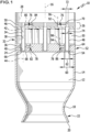
- FIG. 1 A first embodiment of an engine device 10 is shown schematically.
- the engine device 10 comprises a combustion chamber 12 which is delimited by a combustion chamber wall 14.
- the engine device 10 is essentially rotationally symmetrical with respect to a longitudinal axis 16.
- the combustion chamber 12 is essentially hollow-cylindrical and tapers down to a constriction 18, from which an outlet 20 with a widening cross-section is formed.
- the constriction 18 defines a convergent nozzle 22 with a sound passage in the narrowest cross-section, which is predetermined by the constriction 18.
- an end wall 24 Arranged opposite the outlet 20 is an end wall 24 which delimits the combustion chamber 12. Arranged parallel to the end wall 24 and at a distance from it is a second partition wall 26 which, on a side facing away from the combustion chamber 12, delimits a first collecting space 28 for receiving a fluidic oxidizing agent 100.
- the second end wall 26 has a side surface facing the combustion chamber 12 which delimits a second collecting space 30 for receiving a fluidic fuel 102.
- the second collecting space 30 is also delimited by the end wall 24, specifically with a side surface thereof which faces away from the combustion chamber 12.
- the engine device 10 For introducing the fluidic fuel and the fluidic oxidant into the combustion chamber 12, the engine device 10 comprises an injector device 32.
- the injector device 32 defines an injector device longitudinal axis that coincides with the longitudinal axis 16.
- the injector device 32 further comprises a plurality of first injection elements 34 and a plurality of second injection elements 36.
- the first injection elements 34 are designed in the form of a first fluid channel 38 for fluidly connecting the first collection chamber 28 and the combustion chamber 12.
- the second injection elements 36 are designed in the form of second fluid channels 40 for fluidly connecting the second collection chamber 30 and the combustion chamber 12.
- the first injection elements 34 define first injection element longitudinal axes 42.
- the second injection elements 36 define second injection element longitudinal axes 44.
- the first injection elements 34 are arranged on a plate-shaped injector element holder and are designed in the form of an injector sleeve 48.
- the injector element holder 46 delimits the second collection space 30 and rests flat against an injector plate 50 with a second side surface.
- the injector element holder 46 and the injector plate 50 together form the partition wall 26, which separates the collecting spaces 28 and 30 from each other.
- the injector element holder 46 and the injector plate 50 are formed as a single unit in one piece.
- the end wall 24 forms an injection head 52.
- the second injection elements 36 are arranged and formed on or in the injection head 52.
- the second injection elements 36 are designed in the form of bores 54 in the end wall 24.
- the bore longitudinal axes thereof run parallel to the longitudinal axis 16.
- One of the holes 54 is coaxial with the longitudinal axis 16.
- the other holes 54 are arranged on two circles 56 and 58 concentric with the longitudinal axis.
- An inner diameter 60 of the bores 54 is slightly larger than an outer diameter 62 of the injector sleeve 48, so that an annular space 64 is formed which is delimited by the bore 54 on the one hand and the injector sleeve 48 on the other hand and which defines the second fluid channel 40 for the fluidic fuel 102.
- a length of the injector sleeve 48 is selected such that a free end 66 thereof ends in the region of a free end 68 of the bores 54, which points towards the combustion chamber 12.
- the injector plate 50 is provided with a number of holes 70 corresponding to the number of holes 54, the inner diameter 72 of which is slightly smaller than an inner diameter 74 of the injector sleeves 48.
- the holes 70 and 54 thus form a single-stage transition area between the injector plate 50 and the injector holder 46 expanding first fluid channel 38.
- the injector device 32 further comprises a plurality of first resonator elements 76 and a plurality of second resonator elements 78.
- the first resonator elements 76 are each assigned to a first injection element 34
- the second resonator elements 78 are each assigned to a second injection element 36.
- the first resonator elements 76 are each tuned to a natural frequency of the associated first injection element 34.
- the second resonator elements 78 are each tuned to a natural frequency of the associated second injection element 36.
- the first resonator elements 76 define first resonator element longitudinal axes 80 and the second resonator elements 78 define second resonator element longitudinal axes 82.
- the first resonator element longitudinal axes 80 together span a plane running transversely to the longitudinal axis 16, which runs parallel to a plane defined by the second resonator element longitudinal axes 82.
- the first injection element longitudinal axes 42 and the first resonator element longitudinal axes 80 run transversely, namely perpendicularly, to one another.
- the second injection element longitudinal axes 44 and the respectively associated second resonator element longitudinal axes 82 also run transversely, namely perpendicularly, to one another.
- the first resonator elements 76 are fluidically connected to the associated first injection element 34.
- the second resonator elements 78 are fluidically connected to the associated second injection element 36.
- the first resonator elements 76 each define a first resonator cavity 84 which defines a first resonator volume.
- the second resonator elements 78 each define a second resonator cavity 86.
- the first and second resonator elements 76 and 78 respectively open directly into the bore 70 and into the bore 54, respectively.
- the first resonator cavity 84 and the second resonator cavity 86 are in the Figures 1 to 5 In the embodiment of the injector device 32 shown, they are designed in the form of hollow cuboids 88 and 90, respectively. In principle, they can have any shape. In other embodiments, they are designed in the form of hollow cylinders or in the form of hollow spheres.
- first resonator elements 76 and the first collecting chamber 28 are fluidically connected to one another via first flushing channels 92.
- second resonator elements 78 and the second collecting chamber 30 are also fluidically connected to one another via a second flushing channel 94.
- the first flushing channel 92 defines a first flushing channel longitudinal axis 96.
- the second flushing channel 94 defines a second flushing channel longitudinal axis 98.
- the first flushing channel longitudinal axis 96 and the longitudinal axis 16 run parallel or substantially parallel to one another.
- the second flushing channel longitudinal axis 98 and the longitudinal axis 16 also run parallel or substantially parallel to one another.
- the first resonator elements 76 are each assigned to a first injection element 34.
- the second resonator elements 78 are each assigned to a second injection element 36.
- the described embodiment of the injector device 32 comprises nineteen first and second injection elements 34, 36, thus a plurality of first and second injection elements 34, 36.
- the fluidic oxidizing agent 100 flows from the first collection chamber 28 through the bore 70 forming a throttle into the injector sleeve 48, exits at the end 66 thereof and flows into the combustion chamber 12.
- the fluidic fuel 102 flows from the second collection chamber 30 through the annular spaces 64 into the combustion chamber 12 and mixes with the fluidic oxidizing agent 100 when exiting the second injection elements 36.
- the fluidic oxidizing agent 100 can also flow through the first flushing channels 92 into the first resonator elements 76. As a result, the conditions prevailing in the first injection element 34 and in the first resonator element 76 are identical.
- the fluidic fuel 102 flows through the second flushing channels 94 into the second resonator elements 78, so that here too the conditions in the fluidic fuel 102 are identical both in the second resonator element 78 and in the second injection element 36.
- the respective resonator elements 76, 78 can be tuned to natural frequencies of the injection elements 34, 36 independently of the operating conditions of the engine device 10.
- FIGS. 6 to 12 show schematically another embodiment of an engine device 10. Identical elements and components of the Figures 6 to 12 illustrated embodiment of the engine device 10 are provided with the same reference numerals used to designate of elements and components of the Figures 1 to 5 schematically illustrated engine device 10.
- Figure 6 shows schematically a longitudinal sectional view of the engine device 10 in the area of the injector device 32.
- the embodiment of the injector device 32 shown differs from the injector device 32 of the Figures 1 to 5 illustrated embodiment in particular in that the first resonator elements 76 do not open directly into the associated bore 70, but are fluidly connected to it via a first resonator channel 104.
- the second injection element 36 is again formed by the bore 54 in the injection head 52, wherein the bore 54, starting from the second collecting chamber 30, tapers in its inner diameter in one step after approximately two thirds of its length, whereby a throttle is formed in the end wall 24.
- FIG. 6 In the illustrated embodiment of the injector device 32, no second resonator elements 78 are provided.
- second resonator channels 106 are provided, which fluidically connect the second resonator elements 78 and the associated second injection elements 36.
- an optional second resonator element 78 is shown as an example in dashed lines, which is fluidically connected to the second injection element 36 via the associated second resonator channel 106, also shown in dashed lines.
- the second resonator element 78 can, as in Figure 6 shown in dashed lines, can also be fluidically connected to the second collecting chamber 30 via the optional flushing channel 94.
- the first resonator channel 104 defines a first resonator channel volume which is smaller than the first resonator volume. Furthermore, the second Resonator channel 106 has a second resonator channel volume which is smaller than the second resonator volume.
- the first purge channel 92 defines a first purge channel cross-sectional area which is smaller than a first resonator channel cross-sectional area defined by the first resonator channel 104.
- a second purge channel cross-sectional area defined by the second purge channel 94 is smaller than a second resonator channel cross-sectional area defined by the second resonator channel 106.
- the first resonator elements 76 and the second resonator elements 78 of the described embodiments of engine devices 10 are designed in the form of Helmholtz resonators.
- engine devices 10 are designed in the form of ⁇ /4 resonators.
- the first and second resonator elements 76, 78 may be designed partly in the form of Helmholtz resonators and partly in the form of ⁇ /4 resonators.
- the first resonator elements 76 have different shapes.
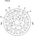
- a total of 42 first injection elements 34 are formed, of which 24 are arranged on an outer circle 59, 12 on a middle circle 58 and six on an inner circle 56.
- the first resonator elements 76a, 76b, 76c, 76d and 76e are formed in the injector plate 50, which can also be referred to as a throttle plate, wherein the first injection elements 34 of the circuit 59 are first resonator element 76a or 76b is assigned, each first injection element 34 of the second circuit 58 is assigned a first resonator element 76c or 76d and each first injection element 34 of the third circuit 56 is assigned a first resonator element 76e.
- the resonator elements 76a, 76b, 76c, 76d and 76e therefore have different shapes and different first resonator volumes.
- first resonator elements 76a, 76b, 76c, 76d and 76e are tuned to different natural frequencies of the first injection elements 34 assigned to them.
- first resonator elements 76a and 76b are tuned to a second eigenmode (2L) of the first injection elements 34, which couples to a first tangential mode of the combustion chamber 12 at about 10 kHz.
- the first resonator elements 76c and 76d are tuned to the third eigenmode (3L) of the first injection elements 34, which couples to a second tangential mode of the combustion chamber 12 at about 15 kHz.
- the first resonator elements 76e are tuned to the fourth eigenmode (4L) of the first injection elements 34, which couples to a first radial mode of the combustion chamber 12 at about 20 kHz.
- the first resonator elements 76a, 76b, 76c, 76d and 76e are each fluidically connected to the first collecting chamber 28 via flushing channels 92a, 92b and 92c.
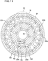
- the injector plate 50 is screwed to the injector element holder 46 with screws 108.
- Blind holes 112 provided with an internal thread 110 are formed in the injector element holder 46.
- the internal threads 110 correspond to external threads 114 of the screws 108.
- holes 124 with recesses are formed in the injector plate 50, through which the part of the screws 108 provided with the external thread 114 passes.
- the blind holes 112 are arranged in a ring shape on a circle 116 which is formed between the circles 58 and 59 concentrically to the longitudinal axis 16.
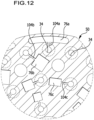
- the first resonator elements 76a and 76b which are fluidly connected to the first injection elements 34 of the outermost circle 59, differ in their shape but not in their tuning to the specific natural frequency of the first injection element 34 of the outermost circle 59.
- the first resonator elements 76c and 76d also differ slightly from one another in their shape. However, these are also each tuned to the same natural frequency of the first injection element 34 of the middle circle 58.
- the different design of the first resonator elements 76a and 76b or 76c and 76d is based on the limited spatial situation, which does not allow to provide only three different first resonator elements 76.
- the first resonator elements 76 are each arranged or formed in the region of an inlet 118 of the first injection element 34 pointing in the direction of the first collecting space 28.
- the second resonator elements 78 are arranged or formed in the region of an inlet 120 of the second injection element 36 pointing in the direction of the second collecting space 30.
- the first resonator elements 76 are arranged in the injector plate 50 or formed.
- the second resonator elements 78 are arranged or formed in the end wall 24, which forms a second injector plate 122.
- the injector plates 50 and 122 are arranged or formed parallel to one another and extend transversely, namely perpendicularly, to the longitudinal axis 16.
- the injector plate 50 is designed in the form of a throttle plate. As described, the bore 70 in the region of the inlet 118 of the first injection element 34 forms a first throttle element which defines a smaller flow cross-section than the remaining part of the first injection element 34.
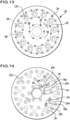
- FIG. 13 Another embodiment of an injector plate 50 is shown schematically in the Figures 13 and 14 shown.
- first resonator elements 76a and 76b are shown schematically.
- the resonator element 76a is fluidically connected to a total of three first injection elements 34 via three first resonator channels 104.
- the first resonator element 76a is fluidically connected to the first collection chamber 28 via a flushing channel 92.
- the Figure 14 The schematically illustrated first resonator element 76b is fluidically connected to two first injection elements 34 via two first resonator channels 104.
- first and second resonator elements 76 and 78 can be assigned to only one injection element 34 in embodiments. In other embodiments of injector devices 32, first resonator elements 76 and second resonator elements 78 can also be assigned to two, three or more first or second injection channels 34, 36. In this way, very compact injector plates 50 can be formed.
- the partition wall 26 of the engine device 10 is subjected to less thermal stress than the combustion chamber wall 14. This makes it possible to form the injector plate 50 from stainless steel or nickel-based alloys.
- the injector plate 50 is formed by an additive manufacturing process.
- selective laser melting can be used here. This enables highly complex structures of the injector plate, in particular for forming the first resonator elements 76.
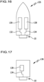
- FIG 16 an embodiment of a spacecraft 126 is shown schematically. It comprises one of the engine devices 10 described above as well as a fuel tank 128 for holding a fluidic, in particular liquid, fuel 102 and an oxidant tank 130 for holding a fluidic, in particular liquid, oxidant 100.
- the oxidant 100 can in particular be liquid oxygen.
- the fuel tank 128 is designed to hold a fluid fuel, for example a liquid fuel in the form of hydrogen or methane.
- the oxidant tank 130 is fluidly connected to the first collection chamber 28 via a fluid line 132.
- the fuel tank 128 is connected to the second collection chamber 30 via a further fluid line 134.
- Figure 17 schematically shows an embodiment of an aircraft 136. It comprises a fuel tank 128 and an engine device 10, which is fluidly connected to the fuel tank 128 via a fluid line 134.
- An oxidizer tank is not necessarily required for the aircraft 136 if the aircraft 136 moves in regions of the atmosphere in which sufficient atmospheric oxygen is available to serve as an oxidizer for the fuel 102 carried by the aircraft 136 in the fuel tank 128.
Landscapes
- Engineering & Computer Science (AREA)
- Chemical & Material Sciences (AREA)
- Combustion & Propulsion (AREA)
- Mechanical Engineering (AREA)
- General Engineering & Computer Science (AREA)
- Fuel-Injection Apparatus (AREA)
Claims (15)
- Dispositif d'injection (32) pour un dispositif de propulsion (10) pour l'introduction d'un carburant (102) fluide, plus particulièrement liquide, et d'un agent oxydant (100) fluide, plus particulièrement liquide, dans une chambre de combustion (12) du dispositif de propulsion (10), ce dispositif d'injection (32) définissant un axe longitudinal (16) et comprenant au moins un premier élément d'injection (34), qui se présente sous la forme d'un premier canal de fluide (38) et qui est conçu pour la liaison fluidique d'une première chambre collectrice (28) pour l'agent oxydant fluide (100) avec la chambre de combustion (12), et au moins un deuxième élément d'injection (36), qui se présente sous la forme d'un deuxième canal de fluide (40) et qui est conçu pour la liaison fluidique d'une deuxième chambre collectrice (30) pour le carburant fluide (102) avec la chambre de combustion (12), dans lequel au moins un premier élément de résonance (76, 76a, 76b, 76c, 76d, 76e) est assigné à l'au moins un premier élément d'injection (34) et/ou dans lequel au moins un deuxième élément de résonance (78) est assigné à l'au moins un deuxième élément d'injection (36), et dans lequel l'au moins un premier élément de résonance (76, 76a, 76b, 76c, 76d, 76e) est syntonisé avec une fréquence propre de l'au moins un premier élément d'injection (34) assigné et/ou dans lequel l'au moins un deuxième élément de résonance (78) est syntonisé avec une fréquence propre de l'au moins un deuxième élément d'injection (36) assigné, caractérisé en ce que l'au moins un premier élément de résonance (76, 76a, 76b, 76c, 76d, 76e) et la première chambre collectrice (28) sont reliés entre eux de manière fluidique par l'intermédiaire d'un premier canal de rinçage (92) et/ou en ce que l'au moins un deuxième élément de résonance (78) et la deuxième chambre collectrice (30) sont reliés entre eux de manière fluidique par l'intermédiaire d'un deuxième canal de rinçage (94), de sorte que, grâce à l'élément de résonance (76, 76a, 76b, 76c, 76d, 76e; 78) respectif, le fluide s'écoulant à travers les éléments d'injection (34, 36), s'écoule également avec une faible vitesse d'écoulement, ce qui permet de s'assurer que, dans l'élément de résonance (76, 76a, 76b, 76c, 76d, 76e; 78) respectif, règnent, à tout moment, les mêmes conditions que dans l'élément d'injection (34, 36) à amortir.
- Dispositif d'injection selon la revendication 1, caractérisé en ce que l'au moins un premier élément de résonance (76, 76a, 76b, 76c, 76d, 76e) est relié de manière fluidique avec l'au moins un premier élément d'injection (34) et/ou en ce que l'au moins un deuxième élément de résonance (78) est relié de manière fluidique avec l'au moins un deuxième élément d'injection (36).
- Dispositif d'injection selon l'une des revendications précédentes, caractérisé en ce que l'au moins un premier élément de résonance (76, 76a, 76b, 76c, 76d, 76e) comprend une première cavité de résonance (84), qui définit un premier volume de résonance, et en ce qu'un premier canal de résonance (104, 104a, 104b, 104c, 104d, 104e) relie de manière fluidique l'au moins un premier élément d'injection (34) et la première cavité de résonance (84) et/ou en ce que l'au moins un deuxième élément de résonance (78) comprend une deuxième cavité de résonance (86), qui définit un deuxième volume de résonance, et en ce qu'un deuxième canal de résonance (106) relie de manière fluidique l'au moins un deuxième élément d'injection (36) et la deuxième cavité de résonance (86),
dans lequel en particuliera) le premier canal de résonance (104, 104a, 104b, 104c, 104d, 104e) définit un premier volume de canal de résonance et dans lequel le premier volume de canal de résonance est inférieur au premier volume de résonance et/ou dans lequel le deuxième canal de résonance (106) définit un deuxième volume de canal de résonance et dans lequel le deuxième volume de canal de résonance est inférieur au deuxième volume de résonance
et/oub) la première cavité de résonance (84) et/ou la deuxième cavité de résonance (86) se présente sous la forme d'un cylindre creux, d'un parallélépipède creux (88, 90) ou d'une sphère creuse. - Dispositif d'injection selon l'une des revendications précédentes, caractérisé en ce quea) l'au moins un premier élément d'injection (34) définit un premier axe longitudinal d'élément d'injection (42) et/ou en ce que l'au moins un deuxième élément d'injection (36) définit un deuxième axe longitudinal d'élément d'injection (44)
et/oub) l'au moins un premier élément de résonance (76, 76a, 76b, 76c, 76d, 76e) définit un premier axe longitudinal d'élément de résonance (80) et/ou en ce que l'au moins un deuxième élément de résonance (78) définit un deuxième axe longitudinal d'élément de résonance (82)
et/ouc) l'au moins un premier élément d'injection (34) et l'au moins un deuxième élément d'injection (36) sont disposés ou réalisés de manière coaxiale entre eux
et/oud) l'au moins un premier canal de rinçage (92) définit un premier axe longitudinal de canal de rinçage (96) et/ou en ce que l'au moins un deuxième canal de rinçage (94) définit un deuxième axe longitudinal de canal de rinçage (98). - Dispositif d'injection selon l'une des revendications précédentes, caractérisé en ce qu'une première surface de section transversale de canal de rinçage, définie par l'au moins un premier canal de rinçage (92), est plus petite qu'une première surface de section transversale de canal de résonance, définie par le premier canal de résonance (104, 104a, 104b, 104c, 104d, 104e) et/ou en ce qu'une deuxième surface de section transversale de canal de rinçage, définie par l'au moins un deuxième canal de rinçage (92), est plus petite qu'une surface de section transversale de canal de résonance, définie par le deuxième canal de résonance (106).
- Dispositif d'injection selon l'une des revendications précédentes, caractérisé en ce quea) l'au moins un premier élément de résonance (76, 76a, 76b, 76c, 76d, 76e) et/ou l'au moins un deuxième élément de résonance (78) se présentent sous la forme d'un résonateur de Helmholtz ou sous la forme d'un résonateur λ/4
et/oub) l'au moins un premier élément de résonance (76, 76a, 76b, 76c, 76d, 76e) est assigné à au moins un premier élément d'injection (34) et/ou en ce que l'au moins un deuxième élément de résonance (78) est assigné à au moins un deuxième élément d'injection (36). - Dispositif d'injection selon l'une des revendications précédentes, caractérisé en ce que le dispositif d'injection (32) comprend une pluralité de premiers éléments d'injection (34) et/ou une pluralité de deuxièmes éléments d'injection (36).
- Dispositif d'injection selon l'une des revendications précédentes, caractérisé en ce que l'au moins un premier élément de résonance (76, 76a, 76b, 76c, 76d, 76e) est disposé ou réalisé au niveau d'une entrée (118), orientée en direction de la première chambre collectrice (28), de l'au moins un premier élément d'injection (34) et/ou en ce que l'au moins un deuxième élément de résonance (78) est disposé ou réalisé au niveau d'une entrée (120), orientée en direction de la deuxième chambre collectrice (30), de l'au moins un deuxième élément d'injection (36).
- Dispositif d'injection selon l'une des revendications précédentes, caractérisé en ce que le dispositif d'injection (32) comprend une première plaque d'injection (50) et une deuxième plaque d'injection (26), en ce que l'au moins un premier élément de résonance (76, 76a, 76b, 76c, 76d, 76e) est disposé ou réalisé dans la première plaque d'injection (50) et/ou en ce que l'au moins un deuxième élément de résonance (78) est disposé ou réalisé dans la deuxième plaque d'injection (122).
- Dispositif d'injection selon l'une des revendications précédentes, caractérisé en ce que l'au moins un premier élément d'injection (34) est disposé sur un support d'élément d'injection en forme de plaque (46) et se présente sous la forme d'une douille d'injection (48).
- Dispositif d'injection selon l'une des revendications précédentes, caractérisé en ce que l'au moins un deuxième élément d'injection (36) est disposé ou réalisé sur ou dans une tête d'injection (52).
- Dispositif d'injection selon l'une des revendications précédentes, caractérisé en ce que l'au moins un deuxième élément d'injection (36) se rétrécit en une étape dans sa section transversale afin de former un deuxième élément d'étranglement.
- Dispositif de propulsion (10), plus particulièrement pour un aéronef (136) et/ou un astronef (126), ce dispositif de propulsion (10) comprenant une chambre de combustion (12) avec une buse (22) et un dispositif d'injection (32) disposé en face de la buse (22), caractérisé en ce que le dispositif d'injection (32) est conçu selon l'une des revendications précédentes.
- Aéronef et/ou astronef (136, 126) avec un dispositif de propulsion (10) et un réservoir de carburant (128) pour le logement d'un carburant (102) fluide, plus particulièrement liquide, caractérisé en ce que le dispositif de propulsion (10) se présente sous la forme d'un dispositif de propulsion (10) selon la revendication 13.
- Procédé de fonctionnement d'un dispositif de propulsion (10), dans lequel un carburant (102) fluide, plus particulièrement liquide, et un agent oxydant (100) fluide, plus particulièrement liquide, sont introduits dans une chambre de combustion (12) du dispositif de propulsion (10) par un dispositif d'injection (32), ce dispositif d'injection (32) comprenant au moins un premier élément d'injection (34), pour la liaison fluidique d'une première chambre collectrice (28) pour l'agent oxydant fluide (100) avec la chambre de combustion (12), et au moins un deuxième élément d'injection (36) pour la liaison fluidique d'une deuxième chambre collectrice (30) pour le carburant fluide (102) avec la chambre de combustion (12), dans lequel les vibrations acoustiques propres dans l'au moins un premier élément d'injection (34) et/ou dans lequel les vibrations acoustiques propres dans l'au moins un deuxième élément d'injection (36) sont amorties, dans lequel au moins un premier élément de résonance (76, 76a, 76b, 76c, 76d, 76e) est assigné à l'au moins un premier élément d'injection (34) et/ou dans lequel au moins un deuxième élément de résonance (78) est assigné à l'au moins un deuxième élément d'injection (36), et dans lequel l'au moins un premier élément de résonance (76, 76a, 76b, 76c, 76d, 76e) est syntonisé avec une fréquence propre de l'au moins un premier élément d'injection (34) assigné et/ou dans lequel l'au moins un deuxième élément de résonance (78) est syntonisé avec une fréquence propre de l'au moins un deuxième élément d'injection (36) assigné, caractérisé en ce que l'au moins un premier élément de résonance (76, 76a, 76b, 76c, 76d, 76e) et la première chambre collectrice (28) sont reliés entre eux de manière fluidique par l'intermédiaire d'un premier canal de rinçage (92) et/ou en ce que l'au moins un deuxième élément de résonance (78) et la deuxième chambre collectrice (30) sont reliés entre eux de manière fluidique par l'intermédiaire d'un deuxième canal de rinçage (94) et en ce que, par l'élément de résonance (76, 76a, 76b, 76c, 76d, 76e; 78) respectif, le fluide s'écoulant à travers les éléments d'injection (34, 36), s'écoule également avec une faible vitesse d'écoulement, ce qui permet de s'assurer que, dans l'élément de résonance (76, 76a, 76b, 76c, 76d, 76e; 78) respectif, règnent, à tout moment, les mêmes conditions que dans l'élément d'injection (34, 36) à amortir.
Applications Claiming Priority (3)
| Application Number | Priority Date | Filing Date | Title |
|---|---|---|---|
| DE102019109929 | 2019-04-15 | ||
| DE102019110258.8A DE102019110258A1 (de) | 2019-04-15 | 2019-04-18 | Injektorvorrichtung für eine Triebwerksvorrichtung, Triebwerksvorrichtung und Luft- und/oder Raumfahrzeug |
| PCT/EP2020/060544 WO2020212396A1 (fr) | 2019-04-15 | 2020-04-15 | Dispositif injecteur pour un dispositif propulseur, dispositif propulseur et aéronef et/ou astronef |
Publications (3)
| Publication Number | Publication Date |
|---|---|
| EP3956607A1 EP3956607A1 (fr) | 2022-02-23 |
| EP3956607C0 EP3956607C0 (fr) | 2025-01-29 |
| EP3956607B1 true EP3956607B1 (fr) | 2025-01-29 |
Family
ID=72613354
Family Applications (1)
| Application Number | Title | Priority Date | Filing Date |
|---|---|---|---|
| EP20719987.8A Active EP3956607B1 (fr) | 2019-04-15 | 2020-04-15 | Dispositif injecteur pour un dispositif propulseur, dispositif propulseur et aéronef et/ou astronef |
Country Status (4)
| Country | Link |
|---|---|
| US (1) | US11906166B2 (fr) |
| EP (1) | EP3956607B1 (fr) |
| DE (1) | DE102019110258A1 (fr) |
| WO (1) | WO2020212396A1 (fr) |
Families Citing this family (3)
| Publication number | Priority date | Publication date | Assignee | Title |
|---|---|---|---|---|
| CN112412661A (zh) * | 2020-12-01 | 2021-02-26 | 上海空间推进研究所 | 火箭发动机直流式喷注器燃烧场分区结构 |
| US11774100B2 (en) * | 2022-01-14 | 2023-10-03 | General Electric Company | Combustor fuel nozzle assembly |
| CN119532759B (zh) * | 2023-08-31 | 2025-11-25 | 中国航发商用航空发动机有限责任公司 | 多燃料燃烧室头部以及多燃料燃烧室的控制方法 |
Family Cites Families (20)
| Publication number | Priority date | Publication date | Assignee | Title |
|---|---|---|---|---|
| US3200589A (en) | 1961-11-03 | 1965-08-17 | North American Aviation Inc | Two stage baffled injector |
| US3242670A (en) | 1962-08-27 | 1966-03-29 | United Aircraft Corp | Segmented baffle injector design |
| US3483698A (en) | 1966-11-22 | 1969-12-16 | United Aircraft Corp | Combustion instability reduction device |
| US4100993A (en) | 1976-04-15 | 1978-07-18 | United Technologies Corporation | Acoustic liner |
| DE3432607A1 (de) * | 1984-09-05 | 1986-03-13 | Messerschmitt-Bölkow-Blohm GmbH, 8012 Ottobrunn | Einrichtung zum daempfen von brennkammerschwingungen bei fluessigkeitsraketentriebwerken |
| FR2685386B1 (fr) | 1991-12-20 | 1994-03-25 | Propulsion Ste Europeenne | Systeme d'amortissement des instabilites de combustion haute frequence dans une chambre de combustion. |
| EP1010939B1 (fr) | 1998-12-15 | 2004-02-11 | ALSTOM (Switzerland) Ltd | Chambre de combustion avec système d'alimentation en carburant amorti acoustiquement |
| DE102004018725B4 (de) * | 2004-04-17 | 2015-02-12 | Astrium Gmbh | Dämpfung von Schwingungen einer Brennkammer durch Resonatoren |
| JP5455411B2 (ja) * | 2009-03-30 | 2014-03-26 | 三菱重工業株式会社 | ロケット用噴射器 |
| US8789372B2 (en) * | 2009-07-08 | 2014-07-29 | General Electric Company | Injector with integrated resonator |
| RU2508506C2 (ru) * | 2009-09-01 | 2014-02-27 | Дженерал Электрик Компани | Способ и установка для ввода текучей среды в камеру сгорания газотурбинного двигателя |
| FR2975440B1 (fr) | 2011-05-17 | 2015-11-20 | Snecma | Systeme d'alimentation et procede de suppression d'effet pogo |
| FR2977639B1 (fr) * | 2011-07-07 | 2013-08-09 | Snecma | Element d'injection |
| FR3026440B1 (fr) | 2014-09-30 | 2016-10-14 | Snecma | Procede de suppression d'effet pogo |
| EP3034945B1 (fr) * | 2014-12-19 | 2018-05-30 | Ansaldo Energia Switzerland AG | Tuyau de carburant de turbine à gaz comprenant un amortisseur |
| FR3032238B1 (fr) | 2015-01-30 | 2017-02-17 | Snecma | Systeme correcteur d'effet pogo capacitif a tube de rejet demi-centre positionnable dans un coude |
| US20160363127A1 (en) * | 2015-06-09 | 2016-12-15 | General Electric Company | Systems and methods for monitoring a compressor |
| US20170211480A1 (en) * | 2016-01-21 | 2017-07-27 | Delavan Inc | Discrete jet orifices |
| US10386074B2 (en) * | 2016-12-09 | 2019-08-20 | Solar Turbines Incorporated | Injector head with a resonator for a gas turbine engine |
| US20190093562A1 (en) * | 2017-09-28 | 2019-03-28 | Solar Turbines Incorporated | Scroll for fuel injector assemblies in gas turbine engines |
-
2019
- 2019-04-18 DE DE102019110258.8A patent/DE102019110258A1/de active Pending
-
2020
- 2020-04-15 WO PCT/EP2020/060544 patent/WO2020212396A1/fr not_active Ceased
- 2020-04-15 EP EP20719987.8A patent/EP3956607B1/fr active Active
-
2021
- 2021-10-14 US US17/450,897 patent/US11906166B2/en active Active
Also Published As
| Publication number | Publication date |
|---|---|
| DE102019110258A1 (de) | 2020-10-15 |
| WO2020212396A1 (fr) | 2020-10-22 |
| US11906166B2 (en) | 2024-02-20 |
| EP3956607C0 (fr) | 2025-01-29 |
| EP3956607A1 (fr) | 2022-02-23 |
| US20220106928A1 (en) | 2022-04-07 |
Similar Documents
| Publication | Publication Date | Title |
|---|---|---|
| EP3956607B1 (fr) | Dispositif injecteur pour un dispositif propulseur, dispositif propulseur et aéronef et/ou astronef | |
| EP1336800B1 (fr) | Procédé de réduction des oscillations induites par la combustion dans les dispositifs de combustion ainsi que brûleur à prémélange pour la mise en oeuvre du procédé | |
| EP2010773B1 (fr) | Aube de turbine | |
| DE69306950T2 (de) | Brennkammer und verfahren dafür | |
| EP0985882B1 (fr) | Amortissement des vibrations dans des combusteurs | |
| DE102011018937A1 (de) | Verbrennungsvorrichtung für eine Gasturbine | |
| EP1651841B1 (fr) | Composant ouvert refroidi destine a une turbine a gaz, chambre de combustion et turbine a gaz | |
| DE112019004946B4 (de) | Brennerkomponente, Brenner, Gasturbine und Herstellungsverfahren für Brennerkomponente | |
| DE102010017778A1 (de) | Vorrichtung zur Brennstoffeinspritzung bei einer Turbine | |
| EP0971172B1 (fr) | Chambre de combustion pour turbine à gaz avec paroi à structure silencieuse | |
| DE102004018725B4 (de) | Dämpfung von Schwingungen einer Brennkammer durch Resonatoren | |
| EP3117148B1 (fr) | Système de combustion avec résonateur | |
| WO2003074936A1 (fr) | Turbine a gaz | |
| DE102010016327A1 (de) | Treibstoffeinspritzdüse | |
| DE102017106758A1 (de) | Schubkammervorrichtung und Verfahren zum Betreiben einer Schubkammervorrichtung | |
| EP2230458A1 (fr) | Agencement de brûleur pour combustibles liquides et procédé de fabrication d'un agencement de brûleur | |
| CH697703A2 (de) | Kraftstoffdüsenanordnung. | |
| EP1605209A1 (fr) | Chambre de combustion avec dispositif d'amortissement des vibrations thermo-acoustiques | |
| DE102023201244A1 (de) | Pilotierungsanordnung, düsenvorrichtung, gasturbinenanordnung und verfahren | |
| EP2187125A1 (fr) | Dispositif et procédé destinés à l'amortissement d'oscillations de combustion | |
| DE2116429A1 (de) | Brennkammer fur Gasturbinenmaschinen | |
| DE69932318T2 (de) | Brennstoffeinspritzvorrichtung für eine gasturbinenbrennkammer | |
| DE102004029029B4 (de) | Einspritzkopf | |
| EP2227629B1 (fr) | Dispositif de chambre de combustion | |
| DE102011000383B4 (de) | Triebwerkvorrichtung und Verfahren zum Betreiben einer Triebwerkvorrichtung |
Legal Events
| Date | Code | Title | Description |
|---|---|---|---|
| STAA | Information on the status of an ep patent application or granted ep patent |
Free format text: STATUS: UNKNOWN |
|
| STAA | Information on the status of an ep patent application or granted ep patent |
Free format text: STATUS: THE INTERNATIONAL PUBLICATION HAS BEEN MADE |
|
| PUAI | Public reference made under article 153(3) epc to a published international application that has entered the european phase |
Free format text: ORIGINAL CODE: 0009012 |
|
| STAA | Information on the status of an ep patent application or granted ep patent |
Free format text: STATUS: REQUEST FOR EXAMINATION WAS MADE |
|
| 17P | Request for examination filed |
Effective date: 20211028 |
|
| AK | Designated contracting states |
Kind code of ref document: A1 Designated state(s): AL AT BE BG CH CY CZ DE DK EE ES FI FR GB GR HR HU IE IS IT LI LT LU LV MC MK MT NL NO PL PT RO RS SE SI SK SM TR |
|
| DAV | Request for validation of the european patent (deleted) | ||
| DAX | Request for extension of the european patent (deleted) | ||
| STAA | Information on the status of an ep patent application or granted ep patent |
Free format text: STATUS: EXAMINATION IS IN PROGRESS |
|
| 17Q | First examination report despatched |
Effective date: 20230329 |
|
| GRAP | Despatch of communication of intention to grant a patent |
Free format text: ORIGINAL CODE: EPIDOSNIGR1 |
|
| STAA | Information on the status of an ep patent application or granted ep patent |
Free format text: STATUS: GRANT OF PATENT IS INTENDED |
|
| INTG | Intention to grant announced |
Effective date: 20231208 |
|
| GRAJ | Information related to disapproval of communication of intention to grant by the applicant or resumption of examination proceedings by the epo deleted |
Free format text: ORIGINAL CODE: EPIDOSDIGR1 |
|
| STAA | Information on the status of an ep patent application or granted ep patent |
Free format text: STATUS: EXAMINATION IS IN PROGRESS |
|
| GRAP | Despatch of communication of intention to grant a patent |
Free format text: ORIGINAL CODE: EPIDOSNIGR1 |
|
| STAA | Information on the status of an ep patent application or granted ep patent |
Free format text: STATUS: GRANT OF PATENT IS INTENDED |
|
| INTG | Intention to grant announced |
Effective date: 20240419 |
|
| GRAJ | Information related to disapproval of communication of intention to grant by the applicant or resumption of examination proceedings by the epo deleted |
Free format text: ORIGINAL CODE: EPIDOSDIGR1 |
|
| STAA | Information on the status of an ep patent application or granted ep patent |
Free format text: STATUS: EXAMINATION IS IN PROGRESS |
|
| GRAP | Despatch of communication of intention to grant a patent |
Free format text: ORIGINAL CODE: EPIDOSNIGR1 |
|
| STAA | Information on the status of an ep patent application or granted ep patent |
Free format text: STATUS: GRANT OF PATENT IS INTENDED |
|
| INTC | Intention to grant announced (deleted) | ||
| INTG | Intention to grant announced |
Effective date: 20240906 |
|
| GRAS | Grant fee paid |
Free format text: ORIGINAL CODE: EPIDOSNIGR3 |
|
| GRAA | (expected) grant |
Free format text: ORIGINAL CODE: 0009210 |
|
| STAA | Information on the status of an ep patent application or granted ep patent |
Free format text: STATUS: THE PATENT HAS BEEN GRANTED |
|
| AK | Designated contracting states |
Kind code of ref document: B1 Designated state(s): AL AT BE BG CH CY CZ DE DK EE ES FI FR GB GR HR HU IE IS IT LI LT LU LV MC MK MT NL NO PL PT RO RS SE SI SK SM TR |
|
| REG | Reference to a national code |
Ref country code: GB Ref legal event code: FG4D Free format text: NOT ENGLISH |
|
| REG | Reference to a national code |
Ref country code: CH Ref legal event code: EP |
|
| REG | Reference to a national code |
Ref country code: DE Ref legal event code: R096 Ref document number: 502020010318 Country of ref document: DE |
|
| REG | Reference to a national code |
Ref country code: IE Ref legal event code: FG4D Free format text: LANGUAGE OF EP DOCUMENT: GERMAN |
|
| U01 | Request for unitary effect filed |
Effective date: 20250226 |
|
| RAP4 | Party data changed (patent owner data changed or rights of a patent transferred) |
Owner name: DEUTSCHES ZENTRUM FUER LUFT- UND RAUMFAHRT E.V. |
|
| U07 | Unitary effect registered |
Designated state(s): AT BE BG DE DK EE FI FR IT LT LU LV MT NL PT RO SE SI Effective date: 20250307 |
|
| U20 | Renewal fee for the european patent with unitary effect paid |
Year of fee payment: 6 Effective date: 20250424 |
|
| PG25 | Lapsed in a contracting state [announced via postgrant information from national office to epo] |
Ref country code: RS Free format text: LAPSE BECAUSE OF FAILURE TO SUBMIT A TRANSLATION OF THE DESCRIPTION OR TO PAY THE FEE WITHIN THE PRESCRIBED TIME-LIMIT Effective date: 20250429 |
|
| PG25 | Lapsed in a contracting state [announced via postgrant information from national office to epo] |
Ref country code: PL Free format text: LAPSE BECAUSE OF FAILURE TO SUBMIT A TRANSLATION OF THE DESCRIPTION OR TO PAY THE FEE WITHIN THE PRESCRIBED TIME-LIMIT Effective date: 20250129 |
|
| PG25 | Lapsed in a contracting state [announced via postgrant information from national office to epo] |
Ref country code: ES Free format text: LAPSE BECAUSE OF FAILURE TO SUBMIT A TRANSLATION OF THE DESCRIPTION OR TO PAY THE FEE WITHIN THE PRESCRIBED TIME-LIMIT Effective date: 20250129 |
|
| PG25 | Lapsed in a contracting state [announced via postgrant information from national office to epo] |
Ref country code: NO Free format text: LAPSE BECAUSE OF FAILURE TO SUBMIT A TRANSLATION OF THE DESCRIPTION OR TO PAY THE FEE WITHIN THE PRESCRIBED TIME-LIMIT Effective date: 20250429 Ref country code: IS Free format text: LAPSE BECAUSE OF FAILURE TO SUBMIT A TRANSLATION OF THE DESCRIPTION OR TO PAY THE FEE WITHIN THE PRESCRIBED TIME-LIMIT Effective date: 20250529 |
|
| PG25 | Lapsed in a contracting state [announced via postgrant information from national office to epo] |
Ref country code: HR Free format text: LAPSE BECAUSE OF FAILURE TO SUBMIT A TRANSLATION OF THE DESCRIPTION OR TO PAY THE FEE WITHIN THE PRESCRIBED TIME-LIMIT Effective date: 20250129 |
|
| PG25 | Lapsed in a contracting state [announced via postgrant information from national office to epo] |
Ref country code: GR Free format text: LAPSE BECAUSE OF FAILURE TO SUBMIT A TRANSLATION OF THE DESCRIPTION OR TO PAY THE FEE WITHIN THE PRESCRIBED TIME-LIMIT Effective date: 20250430 |
|
| PG25 | Lapsed in a contracting state [announced via postgrant information from national office to epo] |
Ref country code: SM Free format text: LAPSE BECAUSE OF FAILURE TO SUBMIT A TRANSLATION OF THE DESCRIPTION OR TO PAY THE FEE WITHIN THE PRESCRIBED TIME-LIMIT Effective date: 20250129 |
|
| PG25 | Lapsed in a contracting state [announced via postgrant information from national office to epo] |
Ref country code: CZ Free format text: LAPSE BECAUSE OF FAILURE TO SUBMIT A TRANSLATION OF THE DESCRIPTION OR TO PAY THE FEE WITHIN THE PRESCRIBED TIME-LIMIT Effective date: 20250129 |
|
| PG25 | Lapsed in a contracting state [announced via postgrant information from national office to epo] |
Ref country code: SK Free format text: LAPSE BECAUSE OF FAILURE TO SUBMIT A TRANSLATION OF THE DESCRIPTION OR TO PAY THE FEE WITHIN THE PRESCRIBED TIME-LIMIT Effective date: 20250129 |
|
| REG | Reference to a national code |
Ref country code: CH Ref legal event code: H13 Free format text: ST27 STATUS EVENT CODE: U-0-0-H10-H13 (AS PROVIDED BY THE NATIONAL OFFICE) Effective date: 20251125 |
|
| PLBE | No opposition filed within time limit |
Free format text: ORIGINAL CODE: 0009261 |
|
| STAA | Information on the status of an ep patent application or granted ep patent |
Free format text: STATUS: NO OPPOSITION FILED WITHIN TIME LIMIT |
|
| PG25 | Lapsed in a contracting state [announced via postgrant information from national office to epo] |
Ref country code: MC Free format text: LAPSE BECAUSE OF FAILURE TO SUBMIT A TRANSLATION OF THE DESCRIPTION OR TO PAY THE FEE WITHIN THE PRESCRIBED TIME-LIMIT Effective date: 20250129 |
|
| 26N | No opposition filed |
Effective date: 20251030 |
|
| PG25 | Lapsed in a contracting state [announced via postgrant information from national office to epo] |
Ref country code: CH Free format text: LAPSE BECAUSE OF NON-PAYMENT OF DUE FEES Effective date: 20250430 |
|
| PGFP | Annual fee paid to national office [announced via postgrant information from national office to epo] |
Ref country code: GB Payment date: 20260320 Year of fee payment: 7 |
|
| PG25 | Lapsed in a contracting state [announced via postgrant information from national office to epo] |
Ref country code: IE Free format text: LAPSE BECAUSE OF NON-PAYMENT OF DUE FEES Effective date: 20250415 |
|
| U20 | Renewal fee for the european patent with unitary effect paid |
Year of fee payment: 7 Effective date: 20260320 |