EP3957192A1 - Fertigungsmaschine zur herstellung von rauchartikeln oder teilen von rauchartikeln - Google Patents
Fertigungsmaschine zur herstellung von rauchartikeln oder teilen von rauchartikeln Download PDFInfo
- Publication number
- EP3957192A1 EP3957192A1 EP21191253.0A EP21191253A EP3957192A1 EP 3957192 A1 EP3957192 A1 EP 3957192A1 EP 21191253 A EP21191253 A EP 21191253A EP 3957192 A1 EP3957192 A1 EP 3957192A1
- Authority
- EP
- European Patent Office
- Prior art keywords
- gluing device
- web
- edge
- manufacturing machine
- housing
- Prior art date
- Legal status (The legal status is an assumption and is not a legal conclusion. Google has not performed a legal analysis and makes no representation as to the accuracy of the status listed.)
- Granted
Links
Images




Classifications
-
- A—HUMAN NECESSITIES
- A24—TOBACCO; CIGARS; CIGARETTES; SIMULATED SMOKING DEVICES; SMOKERS' REQUISITES
- A24C—MACHINES FOR MAKING CIGARS OR CIGARETTES
- A24C5/00—Making cigarettes; Making tipping materials for, or attaching filters or mouthpieces to, cigars or cigarettes
- A24C5/14—Machines of the continuous-rod type
- A24C5/24—Pasting the seam
-
- A—HUMAN NECESSITIES
- A24—TOBACCO; CIGARS; CIGARETTES; SIMULATED SMOKING DEVICES; SMOKERS' REQUISITES
- A24D—CIGARS; CIGARETTES; TOBACCO SMOKE FILTERS; MOUTHPIECES OF CIGARS OR CIGARETTES; MANUFACTURE OF TOBACCO SMOKE FILTERS OR MOUTHPIECES
- A24D3/00—Tobacco smoke filters, e.g. filter tips or filtering inserts; Filters specially adapted for simulated smoking devices; Mouthpieces of cigars or cigarettes
- A24D3/02—Manufacture of tobacco smoke filters
- A24D3/0229—Filter rod forming processes
Definitions
- the present invention relates to a manufacturing machine for the production of smoking articles or parts of smoking articles and to the relative production method.
- the present invention finds advantageous application to a manufacturing machine for the production of cigarette filters, to which the following disclosure will make explicit reference without thereby any loss of generality.
- a manufacturing machine for the production of filters comprises (at least) one forming beam in which a continuous rod of filtering material is formed by wrapping a paper web in a tube shape around a continuous cylinder of filtering material.
- the continuous cylinder of filtering material is fed at the inlet of the forming beam over the paper web, which is subsequently bent in a tube shape along the forming beam.
- a gluing device Before completing the bending in a tube shape of the paper web, a gluing device lays, to one edge of the paper web, a continuous strip of glue which can be a hot glue (i.e., a glue that has a temperature higher than room temperature and that must cool in order to set) or a cold glue typically vinyl based (i.e., a glue that is at room temperature and that must dry in order to set, i.e., must lose the volatile liquid components due to evaporation).
- a hot glue i.e., a glue that has a temperature higher than room temperature and that must cool in order to set
- a cold glue typically vinyl based i.e., a glue that is at room temperature and that must dry in order to set, i.e., must lose the volatile liquid components due to evaporation.
- patent application EP1121869B1 describes an example of a gluing device for a manufacturing machine for the production of smoking articles or parts of smoking articles.
- the type of glue that is used depends on the type of product that is packaged, therefore by varying the product that is packaged, the type of glue that is used can also vary.
- hot glue is normally used for cellulose acetate-based filters
- cold glue can be used for paper filters, especially with an aim to produce biodegradable filters.
- a high degree of adaptability is increasingly required for modern manufacturing machines, i.e., the ability to quickly change and with simple operations the type of product that is packaged; in this perspective it is necessary to be able to quickly change and with simple operations also the type of glue that is used in the manufacturing machine.
- EP3056097A1 , EP2505269A2 , US2004237972A1 , EP1891865A1 and EP2505085A2 describe other examples of gluing devices for laying glue during the production of smoking articles or parts of smoking articles.
- the object of the present invention is to provide a manufacturing machine, and relative method, for the production of smoking articles or parts of smoking articles, which manufacturing machine allows to quickly and simply change the type of glue that is used when it is necessary to change the type of smoking articles or parts of smoking articles that is produced.
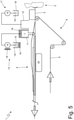
- number 1 denotes as a whole a manufacturing machine for the production of smoking articles (such as cigarettes containing tobacco) or parts of smoking articles (for example filters for traditional cigarettes or for new generation cigarettes).
- the manufacturing machine 1 comprises a preparation unit 2 in which a continuous cylinder 3 (rod) of filtering material (or tobacco) is produced in a known manner and a forming beam 4 in which a paper web 5 (or other containment material) is wound in a tube shape around the continuous cylinder 3 fed by a feeding unit 6.
- a preparation unit 2 in which a continuous cylinder 3 (rod) of filtering material (or tobacco) is produced in a known manner
- a forming beam 4 in which a paper web 5 (or other containment material) is wound in a tube shape around the continuous cylinder 3 fed by a feeding unit 6.
- the continuous cylinder 3 is fed above the paper web 5 which, along the forming beam 4, is subsequently bent in a tube shape around the cylinder 3 itself (as illustrated in Figures 2, 3 and 4 ).
- the manufacturing machine 1 comprises two gluing devices 7 and 8 which are placed side by side at a gluing station placed at the beginning of the forming beam 4 in an area in which the paper web 5 has not yet been bent in a tube shape around the cylinder 3 (as illustrated in Figure 3 ).
- the two gluing devices 7 and 8 operate alternatively, i.e., only one of the two gluing devices 7 and 8 is in operation while the other out of the two gluing devices 7 and 8 is deactivated.
- the gluing device 7 or the gluing device 8 lays a continuous strip of glue 9 or 10 to an edge of the paper web 5: the gluing device 7 lays a hot glue 9 (i.e., a glue that has a temperature higher than the room temperature and must cool in order to set) while the gluing device 8 lays a cold glue 10 typically vinyl based (i.e., a glue that has the room temperature and must dry in order to set i.e., it must lose the volatile liquid components by way of evaporation).
- a hot glue 9 i.e., a glue that has a temperature higher than the room temperature and must cool in order to set
- gluing device 8 lays a cold glue 10 typically vinyl based (i.e., a glue that has the room temperature and must dry in order to set i.e., it must lose the volatile liquid components by way of evaporation).
- the manufacturing machine 1 comprises a housing 11 which is designed to house the gluing device 7 (configured to lay the hot glue 9 on the edge of the web 5) and a housing 12 which is designed to house the gluing device 8 (configured to lay the cold glue 10 on the edge of the paper web 5).
- the two housings 11 and 12 are placed side by side so as to be placed one after the other along the path followed by the paper web 5; in particular, the two housings 11 and 12 are placed rather close together (i.e., at a minimum distance so that the two housings 11 and 12 do not interfere with one another).
- the housing 11 is placed downstream of the housing 12 with respect to the feeding direction of the paper web 5 (and of the continuous cylinder 3); then the gluing device 8 lays the cold glue 10 on the edge of the paper web 5 in an area which is further away from the forming beam 4 than an area in which the gluing device 7 lays the hot glue 9 on the edge of the paper web 5.
- the gluing devices 7 and 8 can be placed opposite one another (preferably one in front of the other), i.e., one on one side of the forming beam 4 and, the other, on the opposite side of the forming beam 4.
- the housings 11, 12 are also placed opposite one another (preferably one in front of the other).
- housing means an element capable of receiving and containing the respective gluing device 7, 8 and to which the gluing device 7, 8 is fixed (for example, by means of a system of screws and bolts or by interlocking) .
- housing means an element to which the respective gluing device 7, 8 is fixed; in this embodiment the gluing device 7, 8 is not contained in the housing 11, 12 but is only supported by the same.
- the two housings 11 and 12 are always both present in the manufacturing machine 1 even if a housing 11 or 12 is empty (if the corresponding gluing device 7 or 8 is not present) or in any case houses the corresponding deactivated gluing device 7 or 8 (i.e., completely unused).
- the housing 11 is movable between a work position, in which the gluing device 7 is placed close to the forming beam 4 so that it is capable of laying the hot glue 9 on the edge of the web 5, and a rest position (disengagement) in which the gluing device 7 is placed further away from the forming beam 4 compared to the work position and, hence, is not capable of laying the hot glue 9 on the edge of the web 5.
- the gluing device 7 when the housing 11 is in the work position the gluing device 7 is necessarily always present (it makes no sense to place the empty housing 11 in the work position), while when the housing 11 is in the rest position the gluing device 7 can be present (i.e., housed in the housing 11) or even absent (i.e., the housing 11 is empty).
- the housing 12 is movable between a work position, in which the gluing device 8 is placed close to the forming beam 4 in order to be able to lay the cold glue 10 on the edge of the web 5, and a rest position (disengagement), in which the gluing device 8 is placed further away from the forming beam 4 compared to the work position and, hence, is not capable of laying the cold glue 10 on the edge of the web 5.
- the gluing device 8 when the housing 12 is in the work position the gluing device 8 is necessarily always present (it makes no sense to place the empty housing 12 in the work position), while when the housing 12 is in the rest position the gluing device 8 can be present (i.e., housed in the housing 12) or even absent (i.e., the housing 12 is empty).
- neither of the two housings 11 and 12 is movable between the work position and the rest position, only the housing 11 is movable between the work position and the rest position, only the housing 12 is movable between the work position and the rest position, or both housings 11 and 12 are movable between the work position and the rest position.
- both gluing devices 7 and 8 can be housed in the respective housings 11 and 12 even if only one out of the two gluing devices 7 and 8 is used, or only the gluing device 7 or 8 that is used is housed in the respective housing 11 or 12.
- the manufacturing machine 1 comprises a feeding system 13 which feeds the hot glue 9 to the housing 11 and is always present regardless of the presence or absence of the gluing device 7; i.e., the gluing device 7 could also be disassembled (or never mounted) on the manufacturing machine 1 whereas the feeding system 13 is in any case always present in the manufacturing machine 1.
- the feeding system 13 comprises a tank 14 which contains the hot glue 9 (the tank 14 could also be a disposable bin which can be replaced from time to time), a pump 15 which draws from the tank 14 to feed the hot glue 9 towards the housing 11, and a series of heating devices 16 which are operated to maintain the entire feeding system 13 (tank 14, pump 15, housing 11 and connection pipes) at a working temperature at which the hot glue 9 is sufficiently fluid.
- the manufacturing machine 1 comprises a feeding system 17 which feeds the cold glue 10 to the housing 12 and is always present regardless of the presence or absence of the gluing device 8; i.e., the gluing device 8 could also be disassembled (or never mounted) on the manufacturing machine 1 whereas the feeding system 17 is in any case always present in the manufacturing machine 1.
- the feeding system 17 comprises a tank 18 which contains the cold glue 10 (the tank 18 could also be a disposable bin which can be replaced from time to time) and a pump 19 which draws from the tank 18 to feed the cold glue 10 towards the housing 12.
- the manufacturing machine 1 comprises a cooling device 20 which is thermally coupled to the forming beam 4 to cool down the forming beam 4 and is used when the gluing device 7 lays the hot glue 9 on the edge of the web 5; in fact, the hot glue 9 must cool in order to set and therefore by cooling the forming beam 4 the setting of the hot glue 9 is accelerated.
- the manufacturing machine 1 comprises a heating device 21 which is thermally coupled to the forming beam 4 in order to heat the forming beam 4 and is used when the gluing device 8 lays the cold glue 10 on the edge of the web 5; in fact the cold glue 10 must dry, i.e., it must lose volatile liquid components by way of evaporation in order to set and therefore, by heating the forming beam 4, the drying (desiccation) of the cold glue 10 is accelerated thus consequently accelerating the setting of the cold glue 10.
- cooling device 20 and the heating device 21 are illustrated in schematic and simplified form.
- the cooling device 20 is placed in the upper part of the forming beam 4, so as to act on the hot glue 9 once the paper web 5 has been bent in a tube shape around the cylinder 3 ( Figure 4 ).
- the heating device 21 is also placed in the upper part of the forming beam 4, so as to act on the cold glue 10 once the paper web 5 has been bent in a tube shape around the cylinder 3 ( Figure 4 ).
- the forming beam 4 has one single seat which is designed to alternatively house either the cooling device 20 or the heating device 21; in this case, only one out of the cooling device 20 and the heating device 21 is present on board the manufacturing machine 1.
- the forming beam 4 has two seats that are distinct and separate from one another and are designed to so that one houses the cooling device 20 and the other houses the heating device 21; in this case, both the cooling device 20 and the heating device 21 can (but do not necessarily have to) be present at the same time in the forming beam 4 (even if obviously it is always and only one out of the cooling device 20 and the heating device 21 to be activated).
- a single thermal device is provided which is thermally coupled to the forming beam 4 and can alternatively be controlled to cool down the forming beam 4, when the gluing device 7 lays the hot glue 9 on the edge of the web 5, or to heat the forming beam 4 when the gluing device 8 lays the cold glue 10 on the edge of the web 5; i.e., the sole thermal device is capable of both heating and cooling (for example by using a reversible heat pump).
- the manufacturing machine 1 comprises a forming beam 4 which is provided with the sole cooling device 20 and is mounted when the gluing device 7 lays the hot glue 9 on the edge of the web 5 and a different and alternative forming beam 4 which is provided with the sole heating device 21 and is mounted when the gluing device 8 lays the cold glue 10 on the edge of the web 5. Consequently, during a format change operation (i.e., an operation in which the manufacturing machine 1 is modified to vary the type of products that are made) which involves passing from hot glue 9 to cold glue 10 or vice versa, it is necessary also to replace the forming beam 4.
- a format change operation i.e., an operation in which the manufacturing machine 1 is modified to vary the type of products that are made
- Figure 1 illustrates a configuration in which both gluing devices 7 and 8 are present at the same time (although obviously only one single gluing device 7 or 8 is activated at a time)
- Figure 5 illustrates a configuration in which only the gluing device 7 is present (whereas both housings 11 and 12 are still present and both feeding systems 13 and 17 which are never disassembled)
- Figure 6 illustrates a configuration in which only the gluing device 8 is present (while, however, both housings 11 and 12 and both feeding systems 13 and 17 are present, which are never disassembled).
- Figure 7 illustrates the manufacturing machine 1 in which the housing 11 (therefore the gluing device 7) is in the work position (and therefore it is active) while the housing 12 (therefore the gluing device 8) is in the rest position (and therefore it is deactivated).
- the present invention also relates to the method for manufacturing smoking articles or parts of smoking articles, comprising the steps of: preparing a continuous cylinder 3; feeding a containing material web 5; bending the web 5 around the cylinder 3; providing a first housing 11 designed to house a first gluing device 7 which is configured to lay a hot glue 9 on the edge of the web 5; providing a second housing 12 designed to house a second gluing device 8 which is configured to lay a cold glue 10 on the edge of the web 5.
- the method comprises the step of activating always and only one single gluing device 7, 8 at a time so that either the hot glue 9 is laid on the edge of the web 5 by means of the first gluing device 7 or, alternatively, the cold glue 10 by means of the second gluing device 8.
- the manufacturing machine 1 described above has numerous advantages.
- the manufacturing machine 1 described above allows to substantially reduce the reconfiguration times and costs when it is necessary to pass from hot glue 9 to cold glue 10 or vice versa; i.e., the manufacturing machine 1 described above reduces to a minimum the time necessary to pass from hot glue 9 to cold glue 10 or vice versa.
- This result is obtained thanks to the fact that the housings 11 and 12 for the two gluing devices 7 and 8 and the feeding systems 13 and 17 are always present and are never disassembled.
- Particularly useful is the fact that the housing 11 or 12, (therefore the gluing device 7 or 8) not used, is placed in the rest position (disengagement) in order not to interfere in any way with the preparation and operation of the other gluing device 8 or 7 being used.
- the manufacturing machine 1 described above is simple and inexpensive to manufacture.
Landscapes
- Packages (AREA)
- Making Paper Articles (AREA)
- Coating Apparatus (AREA)
Applications Claiming Priority (1)
| Application Number | Priority Date | Filing Date | Title |
|---|---|---|---|
| IT102020000020095A IT202000020095A1 (it) | 2020-08-13 | 2020-08-13 | Macchina confezionatrice per la produzione di articoli da fumo o di parti per articoli da fumo |
Publications (2)
| Publication Number | Publication Date |
|---|---|
| EP3957192A1 true EP3957192A1 (de) | 2022-02-23 |
| EP3957192B1 EP3957192B1 (de) | 2026-02-18 |
Family
ID=73139202
Family Applications (1)
| Application Number | Title | Priority Date | Filing Date |
|---|---|---|---|
| EP21191253.0A Active EP3957192B1 (de) | 2020-08-13 | 2021-08-13 | Fertigungsmaschine zur herstellung von rauchartikeln oder teilen von rauchartikeln |
Country Status (2)
| Country | Link |
|---|---|
| EP (1) | EP3957192B1 (de) |
| IT (1) | IT202000020095A1 (de) |
Cited By (1)
| Publication number | Priority date | Publication date | Assignee | Title |
|---|---|---|---|---|
| WO2024230993A1 (de) * | 2023-05-10 | 2024-11-14 | Körber Technologies Gmbh | Verfahren zum betreiben einer strangmaschine und beleimvorrichtung sowie strangmaschine der tabak verarbeitenden industrie oder der trinkhalmindustrie |
Citations (6)
| Publication number | Priority date | Publication date | Assignee | Title |
|---|---|---|---|---|
| EP1121869B1 (de) | 2000-01-31 | 2004-11-17 | G.D S.p.A. | Gummierungseinheit |
| US20040237972A1 (en) | 2001-09-18 | 2004-12-02 | Sonke Horn | Device for combining groups of filter segments for producing multi-segment filters of the tobacco industry, and through drum |
| EP1891865A1 (de) | 2006-08-21 | 2008-02-27 | Hauni Maschinbau AG | Papierbeleimung bei der Strangherstellung |
| EP2505269A2 (de) | 2011-03-28 | 2012-10-03 | HAUNI Maschinenbau AG | Vorrichtung zum Beleimen eines bewegten Umhüllungsstreifens für stabförmige Produkte der Tabak verarbeitenden Industrie und Anlage mit einer derartigen Vorrichtung |
| EP2505085A2 (de) | 2011-03-28 | 2012-10-03 | HAUNI Maschinenbau AG | Vorrichtung und Verfahren zum Beleimen einer Hüllmaterialbahn in einer Maschine der Tabak verarbeitenden Industrie |
| EP3056097A1 (de) | 2015-02-13 | 2016-08-17 | Hauni Maschinenbau GmbH | Vorrichtung zur herstellung von produkten der tabak verarbeitenden industrie |
-
2020
- 2020-08-13 IT IT102020000020095A patent/IT202000020095A1/it unknown
-
2021
- 2021-08-13 EP EP21191253.0A patent/EP3957192B1/de active Active
Patent Citations (6)
| Publication number | Priority date | Publication date | Assignee | Title |
|---|---|---|---|---|
| EP1121869B1 (de) | 2000-01-31 | 2004-11-17 | G.D S.p.A. | Gummierungseinheit |
| US20040237972A1 (en) | 2001-09-18 | 2004-12-02 | Sonke Horn | Device for combining groups of filter segments for producing multi-segment filters of the tobacco industry, and through drum |
| EP1891865A1 (de) | 2006-08-21 | 2008-02-27 | Hauni Maschinbau AG | Papierbeleimung bei der Strangherstellung |
| EP2505269A2 (de) | 2011-03-28 | 2012-10-03 | HAUNI Maschinenbau AG | Vorrichtung zum Beleimen eines bewegten Umhüllungsstreifens für stabförmige Produkte der Tabak verarbeitenden Industrie und Anlage mit einer derartigen Vorrichtung |
| EP2505085A2 (de) | 2011-03-28 | 2012-10-03 | HAUNI Maschinenbau AG | Vorrichtung und Verfahren zum Beleimen einer Hüllmaterialbahn in einer Maschine der Tabak verarbeitenden Industrie |
| EP3056097A1 (de) | 2015-02-13 | 2016-08-17 | Hauni Maschinenbau GmbH | Vorrichtung zur herstellung von produkten der tabak verarbeitenden industrie |
Cited By (1)
| Publication number | Priority date | Publication date | Assignee | Title |
|---|---|---|---|---|
| WO2024230993A1 (de) * | 2023-05-10 | 2024-11-14 | Körber Technologies Gmbh | Verfahren zum betreiben einer strangmaschine und beleimvorrichtung sowie strangmaschine der tabak verarbeitenden industrie oder der trinkhalmindustrie |
Also Published As
| Publication number | Publication date |
|---|---|
| IT202000020095A1 (it) | 2022-02-13 |
| EP3957192B1 (de) | 2026-02-18 |
Similar Documents
| Publication | Publication Date | Title |
|---|---|---|
| EP3957192B1 (de) | Fertigungsmaschine zur herstellung von rauchartikeln oder teilen von rauchartikeln | |
| US8118034B2 (en) | Brand control method for an automatic tobacco article processing machine | |
| EP2969871B1 (de) | Vorrichtung und verfahren zum kombinieren von tabakblättern | |
| JP2019193650A (ja) | 喫煙品の組立てに関する改良 | |
| US1981338A (en) | Machine for making corrugated paper board | |
| US20150224733A1 (en) | Corrugated cardboard installation | |
| JP2010057478A (ja) | タバコ産業の物品を製造するための製造機械 | |
| ITBO20110158A1 (it) | Tamburo di trasferimento o di accompagnamento per spezzoni di filtro o di sigaretta con teste operative portate da bracci radiali. | |
| JP2010522645A (ja) | 切断装置 | |
| JP2010213698A (ja) | たばことフィルタの製品ロッド製造機と協働する搬送システム及び搬送システムの中でたばことフィルタの製品ロッドを搬送する方法 | |
| JP2012231590A (ja) | 絶縁体製造装置および絶縁体製造方法 | |
| US11892827B2 (en) | Method for monitoring a corrugated board production plant | |
| US20210197495A1 (en) | Method and Apparatus For Controlling Air Temperature for Making Seals | |
| CN115486558B (zh) | 叠层芯棒的制备系统 | |
| CN109310142A (zh) | 用于制造烟草行业产品的设备和方法 | |
| NO336301B1 (no) | Fremgangsmåte og apparat for produksjon av en mineralullrørsseksjon for isolasjonsøyemed | |
| WO2020021430A1 (en) | Continuous tape material for inductive heating of tobacco materials comprising reduced strength areas, feeding apparatus and feeding method thereof | |
| GB2231296A (en) | Method of adjusting and controlling a cutting device | |
| US2437295A (en) | Cutting device | |
| JP5300108B1 (ja) | 熱成形装置、及び、その型交換方法 | |
| US8131395B2 (en) | 90 degree ply placement system and method | |
| JP6968076B2 (ja) | タバコ・フィルタを形成するための機械およびタバコ・フィルタを形成するための方法 | |
| EP0654101B1 (de) | Verfahren und vorrichtung zum schneiden einer bahn in der nasspartie einer papiermaschine | |
| JP6527376B2 (ja) | 熱成形装置、及び、シート搬送装置 | |
| KR101620323B1 (ko) | 박막증착장치 |
Legal Events
| Date | Code | Title | Description |
|---|---|---|---|
| PUAI | Public reference made under article 153(3) epc to a published international application that has entered the european phase |
Free format text: ORIGINAL CODE: 0009012 |
|
| STAA | Information on the status of an ep patent application or granted ep patent |
Free format text: STATUS: THE APPLICATION HAS BEEN PUBLISHED |
|
| AK | Designated contracting states |
Kind code of ref document: A1 Designated state(s): AL AT BE BG CH CY CZ DE DK EE ES FI FR GB GR HR HU IE IS IT LI LT LU LV MC MK MT NL NO PL PT RO RS SE SI SK SM TR |
|
| STAA | Information on the status of an ep patent application or granted ep patent |
Free format text: STATUS: REQUEST FOR EXAMINATION WAS MADE |
|
| 17P | Request for examination filed |
Effective date: 20220325 |
|
| RBV | Designated contracting states (corrected) |
Designated state(s): AL AT BE BG CH CY CZ DE DK EE ES FI FR GB GR HR HU IE IS IT LI LT LU LV MC MK MT NL NO PL PT RO RS SE SI SK SM TR |
|
| P01 | Opt-out of the competence of the unified patent court (upc) registered |
Effective date: 20230529 |
|
| STAA | Information on the status of an ep patent application or granted ep patent |
Free format text: STATUS: EXAMINATION IS IN PROGRESS |
|
| 17Q | First examination report despatched |
Effective date: 20240814 |
|
| GRAP | Despatch of communication of intention to grant a patent |
Free format text: ORIGINAL CODE: EPIDOSNIGR1 |
|
| STAA | Information on the status of an ep patent application or granted ep patent |
Free format text: STATUS: GRANT OF PATENT IS INTENDED |
|
| INTG | Intention to grant announced |
Effective date: 20250915 |
|
| GRAS | Grant fee paid |
Free format text: ORIGINAL CODE: EPIDOSNIGR3 |
|
| GRAA | (expected) grant |
Free format text: ORIGINAL CODE: 0009210 |
|
| STAA | Information on the status of an ep patent application or granted ep patent |
Free format text: STATUS: THE PATENT HAS BEEN GRANTED |
|
| AK | Designated contracting states |
Kind code of ref document: B1 Designated state(s): AL AT BE BG CH CY CZ DE DK EE ES FI FR GB GR HR HU IE IS IT LI LT LU LV MC MK MT NL NO PL PT RO RS SE SI SK SM TR |
|
| REG | Reference to a national code |
Ref country code: CH Ref legal event code: F10 Free format text: ST27 STATUS EVENT CODE: U-0-0-F10-F00 (AS PROVIDED BY THE NATIONAL OFFICE) Effective date: 20260218 Ref country code: GB Ref legal event code: FG4D |
|
| REG | Reference to a national code |
Ref country code: DE Ref legal event code: R096 Ref document number: 602021048049 Country of ref document: DE |
|
| REG | Reference to a national code |
Ref country code: IE Ref legal event code: FG4D |