EP3957347B1 - Respirateur pour l'oxygénothérapie à débit élevé - Google Patents
Respirateur pour l'oxygénothérapie à débit élevé Download PDFInfo
- Publication number
- EP3957347B1 EP3957347B1 EP21190924.7A EP21190924A EP3957347B1 EP 3957347 B1 EP3957347 B1 EP 3957347B1 EP 21190924 A EP21190924 A EP 21190924A EP 3957347 B1 EP3957347 B1 EP 3957347B1
- Authority
- EP
- European Patent Office
- Prior art keywords
- ventilator
- hose
- inspiration
- valve
- patient
- Prior art date
- Legal status (The legal status is an assumption and is not a legal conclusion. Google has not performed a legal analysis and makes no representation as to the accuracy of the status listed.)
- Active
Links
Images


Classifications
-
- A—HUMAN NECESSITIES
- A61—MEDICAL OR VETERINARY SCIENCE; HYGIENE
- A61M—DEVICES FOR INTRODUCING MEDIA INTO, OR ONTO, THE BODY; DEVICES FOR TRANSDUCING BODY MEDIA OR FOR TAKING MEDIA FROM THE BODY; DEVICES FOR PRODUCING OR ENDING SLEEP OR STUPOR
- A61M16/00—Devices for influencing the respiratory system of patients by gas treatment, e.g. ventilators; Tracheal tubes
- A61M16/20—Valves specially adapted to medical respiratory devices
- A61M16/201—Controlled valves
- A61M16/202—Controlled valves electrically actuated
- A61M16/203—Proportional
- A61M16/204—Proportional used for inhalation control
-
- A—HUMAN NECESSITIES
- A61—MEDICAL OR VETERINARY SCIENCE; HYGIENE
- A61M—DEVICES FOR INTRODUCING MEDIA INTO, OR ONTO, THE BODY; DEVICES FOR TRANSDUCING BODY MEDIA OR FOR TAKING MEDIA FROM THE BODY; DEVICES FOR PRODUCING OR ENDING SLEEP OR STUPOR
- A61M16/00—Devices for influencing the respiratory system of patients by gas treatment, e.g. ventilators; Tracheal tubes
- A61M16/0051—Devices for influencing the respiratory system of patients by gas treatment, e.g. ventilators; Tracheal tubes with alarm devices
-
- A—HUMAN NECESSITIES
- A61—MEDICAL OR VETERINARY SCIENCE; HYGIENE
- A61B—DIAGNOSIS; SURGERY; IDENTIFICATION
- A61B5/00—Measuring for diagnostic purposes; Identification of persons
- A61B5/08—Measuring devices for evaluating the respiratory organs
-
- A—HUMAN NECESSITIES
- A61—MEDICAL OR VETERINARY SCIENCE; HYGIENE
- A61B—DIAGNOSIS; SURGERY; IDENTIFICATION
- A61B5/00—Measuring for diagnostic purposes; Identification of persons
- A61B5/08—Measuring devices for evaluating the respiratory organs
- A61B5/087—Measuring breath flow
-
- A—HUMAN NECESSITIES
- A61—MEDICAL OR VETERINARY SCIENCE; HYGIENE
- A61M—DEVICES FOR INTRODUCING MEDIA INTO, OR ONTO, THE BODY; DEVICES FOR TRANSDUCING BODY MEDIA OR FOR TAKING MEDIA FROM THE BODY; DEVICES FOR PRODUCING OR ENDING SLEEP OR STUPOR
- A61M16/00—Devices for influencing the respiratory system of patients by gas treatment, e.g. ventilators; Tracheal tubes
- A61M16/0003—Accessories therefor, e.g. sensors, vibrators, negative pressure
-
- A—HUMAN NECESSITIES
- A61—MEDICAL OR VETERINARY SCIENCE; HYGIENE
- A61M—DEVICES FOR INTRODUCING MEDIA INTO, OR ONTO, THE BODY; DEVICES FOR TRANSDUCING BODY MEDIA OR FOR TAKING MEDIA FROM THE BODY; DEVICES FOR PRODUCING OR ENDING SLEEP OR STUPOR
- A61M16/00—Devices for influencing the respiratory system of patients by gas treatment, e.g. ventilators; Tracheal tubes
- A61M16/0057—Pumps therefor
- A61M16/0066—Blowers or centrifugal pumps
-
- A—HUMAN NECESSITIES
- A61—MEDICAL OR VETERINARY SCIENCE; HYGIENE
- A61M—DEVICES FOR INTRODUCING MEDIA INTO, OR ONTO, THE BODY; DEVICES FOR TRANSDUCING BODY MEDIA OR FOR TAKING MEDIA FROM THE BODY; DEVICES FOR PRODUCING OR ENDING SLEEP OR STUPOR
- A61M16/00—Devices for influencing the respiratory system of patients by gas treatment, e.g. ventilators; Tracheal tubes
- A61M16/021—Devices for influencing the respiratory system of patients by gas treatment, e.g. ventilators; Tracheal tubes operated by electrical means
- A61M16/022—Control means therefor
-
- A—HUMAN NECESSITIES
- A61—MEDICAL OR VETERINARY SCIENCE; HYGIENE
- A61M—DEVICES FOR INTRODUCING MEDIA INTO, OR ONTO, THE BODY; DEVICES FOR TRANSDUCING BODY MEDIA OR FOR TAKING MEDIA FROM THE BODY; DEVICES FOR PRODUCING OR ENDING SLEEP OR STUPOR
- A61M16/00—Devices for influencing the respiratory system of patients by gas treatment, e.g. ventilators; Tracheal tubes
- A61M16/021—Devices for influencing the respiratory system of patients by gas treatment, e.g. ventilators; Tracheal tubes operated by electrical means
- A61M16/022—Control means therefor
- A61M16/024—Control means therefor including calculation means, e.g. using a processor
-
- A—HUMAN NECESSITIES
- A61—MEDICAL OR VETERINARY SCIENCE; HYGIENE
- A61M—DEVICES FOR INTRODUCING MEDIA INTO, OR ONTO, THE BODY; DEVICES FOR TRANSDUCING BODY MEDIA OR FOR TAKING MEDIA FROM THE BODY; DEVICES FOR PRODUCING OR ENDING SLEEP OR STUPOR
- A61M16/00—Devices for influencing the respiratory system of patients by gas treatment, e.g. ventilators; Tracheal tubes
- A61M16/06—Respiratory or anaesthetic masks
- A61M16/0666—Nasal cannulas or tubing
- A61M16/0672—Nasal cannula assemblies for oxygen therapy
-
- A—HUMAN NECESSITIES
- A61—MEDICAL OR VETERINARY SCIENCE; HYGIENE
- A61M—DEVICES FOR INTRODUCING MEDIA INTO, OR ONTO, THE BODY; DEVICES FOR TRANSDUCING BODY MEDIA OR FOR TAKING MEDIA FROM THE BODY; DEVICES FOR PRODUCING OR ENDING SLEEP OR STUPOR
- A61M16/00—Devices for influencing the respiratory system of patients by gas treatment, e.g. ventilators; Tracheal tubes
- A61M16/20—Valves specially adapted to medical respiratory devices
- A61M16/201—Controlled valves
- A61M16/202—Controlled valves electrically actuated
-
- A—HUMAN NECESSITIES
- A61—MEDICAL OR VETERINARY SCIENCE; HYGIENE
- A61M—DEVICES FOR INTRODUCING MEDIA INTO, OR ONTO, THE BODY; DEVICES FOR TRANSDUCING BODY MEDIA OR FOR TAKING MEDIA FROM THE BODY; DEVICES FOR PRODUCING OR ENDING SLEEP OR STUPOR
- A61M16/00—Devices for influencing the respiratory system of patients by gas treatment, e.g. ventilators; Tracheal tubes
- A61M16/20—Valves specially adapted to medical respiratory devices
- A61M16/201—Controlled valves
- A61M16/202—Controlled valves electrically actuated
- A61M16/203—Proportional
- A61M16/205—Proportional used for exhalation control
-
- A—HUMAN NECESSITIES
- A61—MEDICAL OR VETERINARY SCIENCE; HYGIENE
- A61M—DEVICES FOR INTRODUCING MEDIA INTO, OR ONTO, THE BODY; DEVICES FOR TRANSDUCING BODY MEDIA OR FOR TAKING MEDIA FROM THE BODY; DEVICES FOR PRODUCING OR ENDING SLEEP OR STUPOR
- A61M16/00—Devices for influencing the respiratory system of patients by gas treatment, e.g. ventilators; Tracheal tubes
- A61M16/0057—Pumps therefor
-
- A—HUMAN NECESSITIES
- A61—MEDICAL OR VETERINARY SCIENCE; HYGIENE
- A61M—DEVICES FOR INTRODUCING MEDIA INTO, OR ONTO, THE BODY; DEVICES FOR TRANSDUCING BODY MEDIA OR FOR TAKING MEDIA FROM THE BODY; DEVICES FOR PRODUCING OR ENDING SLEEP OR STUPOR
- A61M16/00—Devices for influencing the respiratory system of patients by gas treatment, e.g. ventilators; Tracheal tubes
- A61M16/20—Valves specially adapted to medical respiratory devices
- A61M16/208—Non-controlled one-way valves, e.g. exhalation, check, pop-off non-rebreathing valves
- A61M16/209—Relief valves
-
- A—HUMAN NECESSITIES
- A61—MEDICAL OR VETERINARY SCIENCE; HYGIENE
- A61M—DEVICES FOR INTRODUCING MEDIA INTO, OR ONTO, THE BODY; DEVICES FOR TRANSDUCING BODY MEDIA OR FOR TAKING MEDIA FROM THE BODY; DEVICES FOR PRODUCING OR ENDING SLEEP OR STUPOR
- A61M16/00—Devices for influencing the respiratory system of patients by gas treatment, e.g. ventilators; Tracheal tubes
- A61M16/0003—Accessories therefor, e.g. sensors, vibrators, negative pressure
- A61M2016/0027—Accessories therefor, e.g. sensors, vibrators, negative pressure pressure meter
-
- A—HUMAN NECESSITIES
- A61—MEDICAL OR VETERINARY SCIENCE; HYGIENE
- A61M—DEVICES FOR INTRODUCING MEDIA INTO, OR ONTO, THE BODY; DEVICES FOR TRANSDUCING BODY MEDIA OR FOR TAKING MEDIA FROM THE BODY; DEVICES FOR PRODUCING OR ENDING SLEEP OR STUPOR
- A61M16/00—Devices for influencing the respiratory system of patients by gas treatment, e.g. ventilators; Tracheal tubes
- A61M16/0003—Accessories therefor, e.g. sensors, vibrators, negative pressure
- A61M2016/003—Accessories therefor, e.g. sensors, vibrators, negative pressure with a flowmeter
-
- A—HUMAN NECESSITIES
- A61—MEDICAL OR VETERINARY SCIENCE; HYGIENE
- A61M—DEVICES FOR INTRODUCING MEDIA INTO, OR ONTO, THE BODY; DEVICES FOR TRANSDUCING BODY MEDIA OR FOR TAKING MEDIA FROM THE BODY; DEVICES FOR PRODUCING OR ENDING SLEEP OR STUPOR
- A61M16/00—Devices for influencing the respiratory system of patients by gas treatment, e.g. ventilators; Tracheal tubes
- A61M16/0003—Accessories therefor, e.g. sensors, vibrators, negative pressure
- A61M2016/003—Accessories therefor, e.g. sensors, vibrators, negative pressure with a flowmeter
- A61M2016/0033—Accessories therefor, e.g. sensors, vibrators, negative pressure with a flowmeter electrical
-
- A—HUMAN NECESSITIES
- A61—MEDICAL OR VETERINARY SCIENCE; HYGIENE
- A61M—DEVICES FOR INTRODUCING MEDIA INTO, OR ONTO, THE BODY; DEVICES FOR TRANSDUCING BODY MEDIA OR FOR TAKING MEDIA FROM THE BODY; DEVICES FOR PRODUCING OR ENDING SLEEP OR STUPOR
- A61M16/00—Devices for influencing the respiratory system of patients by gas treatment, e.g. ventilators; Tracheal tubes
- A61M16/0003—Accessories therefor, e.g. sensors, vibrators, negative pressure
- A61M2016/003—Accessories therefor, e.g. sensors, vibrators, negative pressure with a flowmeter
- A61M2016/0033—Accessories therefor, e.g. sensors, vibrators, negative pressure with a flowmeter electrical
- A61M2016/0036—Accessories therefor, e.g. sensors, vibrators, negative pressure with a flowmeter electrical in the breathing tube and used in both inspiratory and expiratory phase
-
- A—HUMAN NECESSITIES
- A61—MEDICAL OR VETERINARY SCIENCE; HYGIENE
- A61M—DEVICES FOR INTRODUCING MEDIA INTO, OR ONTO, THE BODY; DEVICES FOR TRANSDUCING BODY MEDIA OR FOR TAKING MEDIA FROM THE BODY; DEVICES FOR PRODUCING OR ENDING SLEEP OR STUPOR
- A61M16/00—Devices for influencing the respiratory system of patients by gas treatment, e.g. ventilators; Tracheal tubes
- A61M16/0003—Accessories therefor, e.g. sensors, vibrators, negative pressure
- A61M2016/003—Accessories therefor, e.g. sensors, vibrators, negative pressure with a flowmeter
- A61M2016/0033—Accessories therefor, e.g. sensors, vibrators, negative pressure with a flowmeter electrical
- A61M2016/0039—Accessories therefor, e.g. sensors, vibrators, negative pressure with a flowmeter electrical in the inspiratory circuit
-
- A—HUMAN NECESSITIES
- A61—MEDICAL OR VETERINARY SCIENCE; HYGIENE
- A61M—DEVICES FOR INTRODUCING MEDIA INTO, OR ONTO, THE BODY; DEVICES FOR TRANSDUCING BODY MEDIA OR FOR TAKING MEDIA FROM THE BODY; DEVICES FOR PRODUCING OR ENDING SLEEP OR STUPOR
- A61M16/00—Devices for influencing the respiratory system of patients by gas treatment, e.g. ventilators; Tracheal tubes
- A61M16/0003—Accessories therefor, e.g. sensors, vibrators, negative pressure
- A61M2016/003—Accessories therefor, e.g. sensors, vibrators, negative pressure with a flowmeter
- A61M2016/0033—Accessories therefor, e.g. sensors, vibrators, negative pressure with a flowmeter electrical
- A61M2016/0042—Accessories therefor, e.g. sensors, vibrators, negative pressure with a flowmeter electrical in the expiratory circuit
-
- A—HUMAN NECESSITIES
- A61—MEDICAL OR VETERINARY SCIENCE; HYGIENE
- A61M—DEVICES FOR INTRODUCING MEDIA INTO, OR ONTO, THE BODY; DEVICES FOR TRANSDUCING BODY MEDIA OR FOR TAKING MEDIA FROM THE BODY; DEVICES FOR PRODUCING OR ENDING SLEEP OR STUPOR
- A61M2202/00—Special media to be introduced, removed or treated
- A61M2202/02—Gases
- A61M2202/0208—Oxygen
-
- A—HUMAN NECESSITIES
- A61—MEDICAL OR VETERINARY SCIENCE; HYGIENE
- A61M—DEVICES FOR INTRODUCING MEDIA INTO, OR ONTO, THE BODY; DEVICES FOR TRANSDUCING BODY MEDIA OR FOR TAKING MEDIA FROM THE BODY; DEVICES FOR PRODUCING OR ENDING SLEEP OR STUPOR
- A61M2205/00—General characteristics of the apparatus
- A61M2205/18—General characteristics of the apparatus with alarm
-
- A—HUMAN NECESSITIES
- A61—MEDICAL OR VETERINARY SCIENCE; HYGIENE
- A61M—DEVICES FOR INTRODUCING MEDIA INTO, OR ONTO, THE BODY; DEVICES FOR TRANSDUCING BODY MEDIA OR FOR TAKING MEDIA FROM THE BODY; DEVICES FOR PRODUCING OR ENDING SLEEP OR STUPOR
- A61M2205/00—General characteristics of the apparatus
- A61M2205/33—Controlling, regulating or measuring
- A61M2205/3331—Pressure; Flow
-
- A—HUMAN NECESSITIES
- A61—MEDICAL OR VETERINARY SCIENCE; HYGIENE
- A61M—DEVICES FOR INTRODUCING MEDIA INTO, OR ONTO, THE BODY; DEVICES FOR TRANSDUCING BODY MEDIA OR FOR TAKING MEDIA FROM THE BODY; DEVICES FOR PRODUCING OR ENDING SLEEP OR STUPOR
- A61M2205/00—General characteristics of the apparatus
- A61M2205/33—Controlling, regulating or measuring
- A61M2205/3379—Masses, volumes, levels of fluids in reservoirs, flow rates
- A61M2205/3382—Upper level detectors
-
- A—HUMAN NECESSITIES
- A61—MEDICAL OR VETERINARY SCIENCE; HYGIENE
- A61M—DEVICES FOR INTRODUCING MEDIA INTO, OR ONTO, THE BODY; DEVICES FOR TRANSDUCING BODY MEDIA OR FOR TAKING MEDIA FROM THE BODY; DEVICES FOR PRODUCING OR ENDING SLEEP OR STUPOR
- A61M2205/00—General characteristics of the apparatus
- A61M2205/70—General characteristics of the apparatus with testing or calibration facilities
-
- A—HUMAN NECESSITIES
- A61—MEDICAL OR VETERINARY SCIENCE; HYGIENE
- A61M—DEVICES FOR INTRODUCING MEDIA INTO, OR ONTO, THE BODY; DEVICES FOR TRANSDUCING BODY MEDIA OR FOR TAKING MEDIA FROM THE BODY; DEVICES FOR PRODUCING OR ENDING SLEEP OR STUPOR
- A61M2230/00—Measuring parameters of the user
- A61M2230/40—Respiratory characteristics
Definitions
- the invention relates to a ventilator for ventilating a patient using high-flow oxygen therapy via a tube system.
- the invention also relates to a ventilation system for ventilating a patient using high-flow oxygen therapy.
- an oxygen concentration and a gas flow are typically set on a corresponding ventilator.
- This gas flow is then fed to a patient to be ventilated via a patient interface.
- the gas flow takes place via a hose system that includes at least one hose.
- the patient interface ensures ventilation by means of a dynamic overpressure, which can be provided by so-called prongs, for example.
- the gas flow mostly flows past the patient into the environment.
- the patient interface does not seal the patient's airways, whereby the degree of the corresponding leakage between the patient to be ventilated and the patient interface determines the pressure provided within the patient's airways. At the same time, possible dead space is flushed out by turbulence in the gas.
- An exhalation flow sensor with a flap is known, which is designed to generate a pressure difference upstream and downstream of the flap.
- the exhalation flow sensor has means for measuring the pressure difference and means for calculating a flow rate based on the pressure difference.
- An oxygen supply device is designed to supply the person with a higher oxygen flow during an inhalation phase.
- a system for selectively administering a high flow of oxygen wherein a source of compressed oxygen is connected to a first nasal cannula via a valve for controlling the oxygen flow.
- a pressure sensor is arranged in a second nasal cannula.
- the object of the present invention is to provide an improved ventilator, in particular a particularly safe ventilator for high-flow oxygen therapy.
- a ventilator for ventilating a patient by high-flow oxygen therapy via a hose system wherein the ventilator has at least one sensor element, at least one controllable inspiration or expiration valve and a control unit.
- the at least one sensor element is arranged and designed to determine and output a measured variable within the hose system, wherein the measured variable indicates a gas flow within the hose system.
- the at least one controllable inspiration and/or expiration valve in particular the at least one electrically controllable inspiration or Expiratory valve is arranged and designed to allow a flow of a breathing gas out of a ventilation circuit of the ventilator.
- the control unit regulates a ventilation pressure provided by the ventilator via the at least one sensor element and the at least one inspiration or expiration valve such that a predetermined maximum pressure is not exceeded in a predetermined area of the hose system.
- a pressure level that is dangerous for the patient being ventilated can be automatically avoided during ventilation without having to change the gas flow provided. This means that the desired high-flow oxygen therapy can be carried out over the entire intended duration of the therapy without the risk of excessive pressure on the patient.
- the sensor element comprises at least one sensor part and a connecting part that connects the sensor part to the control unit directly or indirectly.
- the at least one sensor element is a sensor, such as a pressure sensor or a flow sensor. The exact structure of such sensors is known and is therefore not explained below.
- An inspiratory valve is a valve through which a gas flow intended for the patient's inspiration can escape.
- An expiratory valve is a valve through which a patient's exhaled gas can escape.
- an inspiration valve is arranged in the region of an inspiration tube and an expiration valve is arranged in the region of an expiration tube.
- the control unit preferably comprises a memory module on which the predetermined maximum pressure is stored. When regulating the ventilation pressure, the control unit accesses this stored predetermined maximum pressure and compares it with a value that is indicated by the output measurement variable.
- the predetermined maximum pressure is a value that indicates a maximum pressure present. In one embodiment, the maximum pressure is a value from which the maximum pressure present in the predetermined area of the hose system can be directly determined.
- the components of the ventilator according to the invention can be arranged in a common housing or at least partially spaced apart from one another.
- the hose system is not part of the ventilator according to the invention.
- the ventilation circuit can be open in the sense of the invention, for example for a one-tube structure of the tube system, or closed, such as when providing an inspiration tube and an expiration tube.
- the ventilator is designed to keep the at least one inspiration or expiration valve closed if the predetermined maximum pressure is not reached in the predetermined range of the hose system.
- the inspiration or expiration valve does not influence the gas flow during high-flow oxygen therapy as long as there is no critical pressure in the predetermined range.
- the at least one sensor element is arranged within an expiration tube.
- a measurement value is determined that indicates a quantity of gas flowing past a patient interface per unit of time.
- the sensor element can thus determine whether an unusually large quantity of gas is currently collecting in the area of the expiration tube, which can be evidence, for example, that the patient interface is too close to the patient.
- the control unit can decide particularly reliably that the corresponding inspiration or expiration valve must be controlled in such a way that the pressure applied to the patient is reduced. According to the invention, the gas flow to the patient is not reduced.
- control unit regulates the ventilation pressure provided without changing the output of a blower of the ventilator or the like. This ensures a constant gas flow to the patient, as is necessary for high-flow oxygen therapy.
- the control unit preferably regulates this exclusively by opening the corresponding inspiration or expiration valve when the pressure exceeds the predetermined maximum pressure within the predetermined range of the hose system.
- the inspiration or expiration valve is an electrically controllable inspiration or expiration valve. This allows the control unit to regulate particularly reliably and quickly.
- the inspiration or expiration valve can be controlled pneumatically or mechanically in another way by the control unit.
- the at least one sensor element is a pressure sensor and/or a flow sensor.
- a sensor element can be directly, without time-consuming algorithms for signal evaluation, display the current pressure and/or the current pressure over a specific gas flow.
- the at least one sensor element is arranged in the predetermined area of the hose system. This makes it possible to determine directly from the specific sensor data whether the predetermined maximum pressure has been exceeded or not.
- the at least one sensor element is arranged at a distance from the predetermined area of the hose system. In this embodiment, the specific measurement value must be converted to a value that indicates the pressure in the predetermined area of the hose system.
- control unit is further designed to regulate the ventilation pressure provided based on predetermined calibration information.
- the predetermined calibration information is preferably stored in a memory module of the control unit.
- the predetermined calibration information can be used to draw particularly reliable conclusions about the pressure within the predetermined range of the hose system from the specific measured variable.
- the calibration information indicates a connection between the pressure present in the predetermined area of the hose system and the gas flow measured by the at least one flow sensor. Such a connection can be made by a functional assignment, by a graphical assignment via a diagram and/or via a predetermined assignment of value pairs.
- the calibration information preferably takes geometric properties of the hose system into account.
- calibration information is determined as part of a test operation of the ventilator before a subsequent use of the ventilator on the patient to be ventilated.
- the calibration information is further based on a hose resistance, in particular a predetermined hose resistance, of the hose system.
- the geometry of at least part of the hose system is taken into account when determining the calibration information.
- This makes it particularly advantageous to draw conclusions about the pressure present in the predetermined area from the measured variable, such as a gas flow or a pressure.
- the measured variable is particularly preferably determined in the predetermined area. For example, based on the hose resistance, a measured gas flow can be used to draw direct conclusions about the pressure indicated by the gas flow within this hose area.
- the predetermined area of the hose system is particularly preferably an end of an inspiration or expiration hose pointing towards the patient.
- excessive pressure on the patient can be avoided particularly reliably, since the predetermined maximum pressure is not exceeded according to the invention directly in the area of the patient, namely at a corresponding end of the inspiration or expiration hose. If this predetermined maximum pressure is exceeded in this area on the patient, the control unit opens the inspiration or expiration valve and reduces the pressure to protect the patient.
- the at least one inspiration or expiration valve is arranged together with the control unit in a housing of the ventilator.
- the ventilator according to the invention can advantageously be used for different hose systems without the functionality of the inspiration or expiration valve being impaired.
- the inspiration or expiration valve is preferably arranged in the area of a gas supply to the hose system or a gas return from the hose system.
- the at least one inspiration or expiration valve can only be present in an open valve position and in a closed valve position.
- the inspiration or expiration valve is designed to be particularly simple. This means that this valve can be particularly robust and inexpensive to manufacture. Such a valve with only two different valve positions can have a particularly high level of reliability, which is advantageous for the reliability of the ventilator according to the invention.
- the predetermined maximum pressure is preferably individually adjustable.
- the predetermined maximum pressure is between 5 mbar and 25 mbar, in particular between 10 mbar and 20 mbar, particularly preferably around 12 mbar.
- the predetermined maximum pressure is individually adjustable between 5 mbar and 25 mbar, in particular between 10 mbar and 20 mbar.
- the ventilator is further designed to indicate via a display unit when the control unit has actuated the inspiration or expiration valve. This informs a user that the predetermined maximum pressure in the predetermined area of the hose system has been exceeded. This can indicate, for example, that a desired leak is not present at an interface of the hose system to the patient.
- a ventilation system for ventilating a patient by means of high-flow oxygen therapy comprising a ventilator according to the invention according to at least one of the preceding embodiments, and a hose system with an inspiration hose and an expiration hose, wherein the hose system is connected to the ventilator for providing a ventilation circuit.
- the ventilation system according to the invention comprises the ventilator according to the invention and thus also all the advantages of this ventilator.
- the tube system can be adapted to the ventilator in terms of its geometry so that the control unit can regulate the inspiration or expiration valve particularly reliably for the existing tube geometry.
- the at least one sensor element is arranged within the hose system and is connected to the control unit of the ventilator by means of signals.
- the inspiration or expiration valve is preferably arranged in the hose system to allow a flow of breathing gas out of the ventilation circuit of the ventilator directly at the hose system.
- a connection of the hose system to the patient is provided via prongs.
- a connection via prongs can change while these prongs are being worn with regard to the leakage provided, so that the ventilator according to the invention is particularly advantageous for the use of such prongs. In this way, the predetermined maximum pressure can be avoided even if the leakage changes over time.
- the method according to the third aspect of the disclosure is carried out by the ventilator according to the first aspect of the invention, so that it includes the advantages of the ventilator.
- the method allows a constant gas flow to the patient during high-flow oxygen therapy while at the same time avoiding the risk of too high a gas pressure on the patient.
- a computer program with a program code for carrying out a method according to the third aspect of the disclosure is proposed when the program code is executed on a computer, a processor or a programmable hardware component.
- the program code is executed on a computer, a processor or a programmable hardware component.
- several steps of the method are carried out by a common computer, a common processor or a common programmable hardware component.
- the individual steps are separated from one another at least at the software level by corresponding software blocks.
- all steps of the method are carried out on a common computer, a common processor or a common programmable hardware component.
- Fig. 1 shows a schematic representation of a first embodiment of a ventilator 100 according to a first aspect of the invention.
- the ventilator 100 is designed to ventilate a patient 102 by means of high-flow oxygen therapy via a hose system 104.
- the ventilator 100 comprises at least one sensor element 110, at least one controllable inspiration or expiration valve 120 and a control unit 130.
- the at least one sensor element 110 is a flow sensor that is arranged and designed to determine and output a measured variable 112, namely in this case a gas flow in the region of the sensor element 110, within the hose system 104.
- the flow sensor is arranged in an expiration hose 106 of the hose system 104 at an end of this expiration hose 106 pointing towards the patient 102.
- the flow sensor is connected to the control unit 130 via a cable.
- the at least one sensor element is connected wirelessly to the control unit.
- the sensor element is indirectly connected to the control unit via a further processing unit of the ventilator.
- connection between the control unit 130 and the sensor element 110 is made via an interface 114 on the housing 101 of the ventilator 100.
- the data provided, which indicate the measured variable 112, are provided via this interface 114 via a signal that can be read by the control unit 130.
- the at least one controllable inspiration or expiration valve 120 is arranged and designed to enable a flow of a respiratory gas out of a ventilation circuit 107 of the ventilator 100.
- this is an expiration valve that is designed in the area of a receptacle 122 of the ventilator 100 for the expiration tube 106.
- the valve according to the invention is an inspiration valve that is designed in a receptacle of the ventilator for an inspiration tube.
- the expiration valve 120 in the exemplary embodiment shown is controlled by the control unit 130 in such a way that it remains closed as long as the predetermined maximum pressure is not reached in the predetermined area 140 of the tube system 104. Only after such a predetermined maximum pressure has been indicated via the sensor element 110 is the expiratory valve 120 opened, thereby enabling a flow of gas out of the ventilation circuit 107.
- the control unit 130 is connected to the sensor element 110 via the interface 114 and to the expiration valve 120 directly via a corresponding valve cable 132.
- the control unit is connected to the inspiration or expiration valve wirelessly.
- the connection via the valve cable 132 enables electrical control, via which a valve position of the expiration valve 120 can be changed electrically.
- the inspiration or expiration valve is controlled by the control unit via a pneumatic control means and/or via a mechanical control means.
- the control unit 130 is designed to control a valve position generated by the ventilator 100.
- the predetermined region 140 is here an area on the Y-piece 109 of the hose system 104. Because the sensor element 110 is arranged near the Y-piece 109, the gas pressure in the region of the Y-piece 109 can be determined from the output measurement variable 112.
- the predetermined maximum pressure is between 5 mbar and 25 mbar, in particular between 10 mbar and 20 mbar, particularly preferably about 12 mbar.
- the tube system 104 is connected to the patient 102 via a patient interface 150.
- the patient interface 150 is merely a connection to a nasal area of the patient 102. This is a connection that allows a leak between the tube system 104 and the patient 102.
- the patient interface is a connection to the nasal area and a mouth area of the patient.
- the patient interface 150 is preferably a so-called prong that is inserted into a respective nostril of the patient and thus directly introduces the gas to be used for ventilating the patient 102 into the airways of the patient 102.
- the ventilation circuit 107 is preferably provided via a blower (not shown) of the ventilator 100.
- a blower not shown
- the performance of this blower or a similar device providing a gas flow is not changed by the control unit 130 when the predetermined maximum pressure is present in the predetermined range 140.
- the regulation by the control unit 130 is based exclusively on the control of the inspiration or expiration valve 120.
- the control unit 130 is arranged inside the housing 101 of the ventilator 100.
- the inspiration or expiration valve 120 is arranged inside the receptacle 122 and thus also on the housing 101.
- the sensor element 110 is arranged on the hose system 104 and thus outside the housing 101. In an embodiment not shown, the sensor element is also arranged inside and/or on the housing of the ventilator according to the invention. A greater distance between the sensor element and the predetermined area of the hose system than in the embodiment shown means that the determined measurement variable must be converted into a measurement variable that is likely to be present in the predetermined area using a corresponding conversion.
- the inspiration or expiration valve 120 has an electrically controllable flap that is either in an open or closed state, depending on the control by the control unit 130. Accordingly, the present expiration valve can be switched between the corresponding open valve position and the corresponding closed valve position via the electrical control by the control unit 130.
- the corresponding valve is designed such that it can provide a plurality of different flow resistances within the scope of a plurality of valve positions. The exact design of such a valve is known to the person skilled in the art and is therefore not explained in detail below.
- Fig. 2 shows a schematic representation of a second embodiment of a ventilator 200 according to the first aspect of the invention.
- the 200 ventilator differs from the one in Fig. 1
- the ventilator 100 shown in FIG. 1 is characterized in that the hose system 204 consists only of an inspiration hose 208 and the corresponding patient interface 250 with the patient 102.
- the complete provided respiratory gas flow 207 should therefore be supplied via the patient interface 250, which in this case is a Connection to the nose of the patient 102, to the patient 102.
- the respiratory gas flow 207 forms a ventilation circuit for the structure of the hose system 204 shown. If a leak between the patient interface 205 and patient 102 is too small and therefore the gas pressure on the patient exceeds a safe level, the at least one sensor element 210, which is a pressure sensor in the present case, detects such an increase in the gas pressure.
- the inspiration valve 220 which is formed on an extension of the inspiration tube 208, opens.
- the inspiration valve 220 like the expiration valve from Fig. 1 , a flap that can only switch between an open position and a closed position depending on an electrical control.
- the provided breathing gas flow 207 is selected such that all of the provided breathing gas exits the patient interface 250. Part of the breathing gas is guided into the nose of the patient 102 and the remaining part is guided past this patient via a leak between the patient interface 250 and the patient 102. Only if the prongs of the patient interface 250 are too close to the nose and the leak is correspondingly too small does the pressure within the hose system 204 rise and, without appropriate regulation by the control unit 230, can lead to a pressure above the predetermined maximum pressure that is detrimental to the health of the patient 102.
- Calibration information 260 is permanently stored in the control unit 230.
- the control unit regulates the corresponding valve 220 depending on the calibration information 260.
- the calibration information represents an assignment between the pressure measured by the pressure sensor 210 and the pressure present in the predetermined range 140.
- the calibration information 260 is stored in a memory module (not shown) of the control unit 230.
- the ventilator 200 also includes an output unit 270, which uses a display 272 to indicate whether the inspiration or expiration valve 220 has been activated to avoid the maximum pressure in the predetermined range 140.
- an output unit 270 uses a display 272 to indicate whether the inspiration or expiration valve 220 has been activated to avoid the maximum pressure in the predetermined range 140. This allows a user of the ventilator 200, such as medical professionals, to recognize that the hose system 204 may not currently be loosely attached to the patient 102 via the patient interface 250 as desired. In this sense, an action by the medical professionals to regulate the pressure within the hose system 204 can be triggered directly via the output unit 270.
- Fig. 3 shows a schematic representation of an embodiment of a ventilation system 305 according to a second aspect of the invention.
- the ventilation system 305 comprises a ventilator 300 according to the first aspect of the invention and the hose system 304.
- the hose system 304 is connected to the ventilator 300 to provide the ventilation circuit 107.
- the hose system 304 has the same structure as the hose system 104 from Fig. 1 and accordingly has an expiratory tube 306 and an inspiratory tube 308.
- the ventilator 300 has two sensor elements 310, 310 ⁇ , both of which are arranged on the expiration tube 306. These are a flow sensor and a pressure sensor.
- the control unit 330 can determine particularly reliably whether the inspiration or expiration valve 320 must be activated in order to avoid the predetermined maximum pressure in the predetermined range 140.
- the control unit 330 accesses a stored calibration information 360, which in the illustrated embodiment comprises a hose resistance 362, in particular a predetermined hose resistance, of the hose system 304.
- the ventilator It is automatically recognized which hose system 304 is connected to the ventilator and, depending on the stored predetermined hose resistance of the recognized hose system 304, the corresponding calibration information assigned to the hose resistance is used, which provides a reliable assignment of the measured gas flow and the measured gas pressure to the gas pressure present in the predetermined area 140 for the existing hose resistance 362.
- the automated recognition of the existing hose system 304 takes place, for example, by reading out an identification number in the area of a receptacle 322 of a respective hose by the ventilator 300.
- the use of two sensors for the ventilator according to the invention can increase reliability against the failure of a sensor. For example, the two determined measured variables can be compared with one another in order to detect an error in the determination of a measured variable and to output a corresponding error signal.
- an expiration valve 320 is used as the valve, which is arranged at the end of the expiration tube 306 facing the ventilator 300.
- the valve is in Fig. 3 in an open state, i.e. with the flap open. Consequently, in the state shown, the predetermined maximum pressure in the predetermined area 140 has been reached or it has been determined that this maximum pressure is likely to be reached with unchanged operation, so that a gas flow is released from the hose system 304 in an environment of the ventilator 300 via the expiration valve 320.
- all positions on the respective hose system used or within a gas duct in the housing of the ventilator according to the invention are possible for the position of the respective at least one sensor element and the at least one controllable inspiration or expiration valve.
- the corresponding valve only needs to have a pneumatic connection to the predetermined area of the hose system in order to enable the existing pressure to be regulated there. This is also possible, for example, for a valve inside the housing of the ventilator.
- communication between the sensor elements 310, 310 ⁇ and the control unit 330, as well as between the expiration valve 320 and the control unit 330, is cable-based. In an embodiment not shown, communication is at least partially wireless.
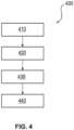
- Fig. 4 shows a flowchart of an embodiment of a method 400 according to a third aspect of the disclosure.
- the method 400 according to the disclosure is designed to regulate a ventilation pressure provided by a ventilator during high-flow oxygen therapy via a hose system. For this purpose, it has the steps shown below.
- a first step 410 comprises providing at least one controllable inspiration or expiration valve, in particular an electrically controllable inspiration or expiration valve, for enabling a flow of a respiratory gas out of a ventilation circuit of the ventilator.
- a subsequent step 420 includes determining a measured variable within the hose system, wherein the measured variable indicates a gas flow within the hose system.
- a step 430 immediately following step 420 comprises outputting this measurement variable.
- a final step 440 includes regulating a ventilation pressure provided by the ventilator via the at least one inspiration or expiration valve such that a predetermined maximum pressure in a predetermined region of the hose system is not exceeded.
- the first step 410 is typically carried out during the manufacture of the ventilator and/or a system comprising a ventilator and a tubing system. After the manufacture of this ventilator or this system, only steps 420, 430 and 440 follow.
- steps 420 and 430 i.e. determining and outputting the measured variable, are preferably carried out immediately one after the other.
- the time offset between these two steps is preferably less than 20 seconds, in particular less than 10 seconds, preferably less than 5 seconds.
- the two steps 420 and 430 are preferably carried out independently of step 440 at recurring time intervals.
- the measured variable is determined and output again after less than 1 minute, in particular after less than 30 seconds, particularly preferably after less than 5 seconds.
- the final step 440 is preferably only carried out if the output measured value indicates that the predetermined maximum pressure has been exceeded or is likely to be exceeded. If the predetermined maximum pressure is not likely to be reached in view of the determined measured variable, no control according to step 440 preferably takes place.
Landscapes
- Health & Medical Sciences (AREA)
- Life Sciences & Earth Sciences (AREA)
- Pulmonology (AREA)
- General Health & Medical Sciences (AREA)
- Veterinary Medicine (AREA)
- Biomedical Technology (AREA)
- Heart & Thoracic Surgery (AREA)
- Public Health (AREA)
- Engineering & Computer Science (AREA)
- Animal Behavior & Ethology (AREA)
- Emergency Medicine (AREA)
- Hematology (AREA)
- Anesthesiology (AREA)
- Otolaryngology (AREA)
- Pathology (AREA)
- Biophysics (AREA)
- Physics & Mathematics (AREA)
- Medical Informatics (AREA)
- Molecular Biology (AREA)
- Surgery (AREA)
- Physiology (AREA)
- Measurement Of The Respiration, Hearing Ability, Form, And Blood Characteristics Of Living Organisms (AREA)
- Respiratory Apparatuses And Protective Means (AREA)
Claims (13)
- Respirateur (100) permettant de faire respirer un patient (102) par une oxygénothérapie à haut débit par l'intermédiaire d'un système de tubes (104),dans lequel le respirateur (100) présente- au moins un élément formant capteur (110) qui est disposé et configuré pour déterminer et émettre une grandeur de mesure (112) à l'intérieur du système de tubes (104), dans lequel la grandeur de mesure (112) indique un écoulement de gaz à l'intérieur du système de tubes (104),- au moins une soupape d'inspiration ou d'expiration (120) pouvant être commandée qui est disposée et conçue pour permettre un écoulement d'un gaz respiratoire hors d'un circuit respiratoire (107) du respirateur (100), et- une unité de commande (130),caractérisé en ce quel'unité de commande (130) est configurée pour réguler une pression de respiration fournie par le respirateur (100) par l'intermédiaire de l'au moins un élément formant capteur (110) et de l'au moins une soupape d'inspiration ou d'expiration (120) de telle sorte qu'une pression maximale prédéterminée n'est pas dépassée dans une zone prédéterminée (140) du système de tubes (104), dans lequel l'unité de commande (130) est configurée pour exécuter la régulation de la pression de respiration fournie sans modifier pour cela une puissance d'une soufflante du respirateur (100) ou similaire.
- Respirateur (100) selon la revendication 1,
dans lequel le respirateur (100) est conçu pour maintenir l'au moins une soupape d'inspiration ou d'expiration (120) fermée si la pression maximale prédéterminée n'est pas atteinte dans la zone prédéterminée (140) du système de tubes (104). - Respirateur (100) selon la revendication 1 ou 2,
dans lequel l'au moins un élément formant capteur (110) est disposé à l'intérieur d'un tube d'expiration (106). - Respirateur (100) selon au moins l'une des revendications précédentes,
dans lequel la soupape d'inspiration ou d'expiration (120) est une soupape d'inspiration ou d'expiration pouvant être commandée électriquement. - Respirateur (100) selon au moins l'une des revendications précédentes,
dans lequel l'au moins un élément formant capteur (110) est un capteur de pression et/ou un capteur d'écoulement. - Respirateur (200) selon au moins l'une des revendications précédentes,
dans lequel l'unité de commande (230) est en outre configurée pour réguler la pression de respiration fournie sur la base d'une information d'étalonnage (260) prédéterminée. - Respirateur (200) selon les revendications 5 et 6,
dans lequel l'information d'étalonnage (260) indique une relation entre la pression présente dans la zone prédéterminée du système de tubes (204) et l'écoulement de gaz mesuré par le capteur d'écoulement en tant que l'au moins un élément formant capteur (110). - Respirateur (300) selon la revendication 6 ou 7,
dans lequel l'information d'étalonnage (360) est en outre basée sur une résistance de tube (362), en particulier une résistance de tube prédéterminée, du système de tubes (304). - Respirateur (100) selon au moins l'une des revendications précédentes,
dans lequel la zone prédéterminée (140) du système de tubes (104) est une extrémité d'un tube d'inspiration ou d'expiration (106) orientée vers le patient (102). - Respirateur (100) selon au moins l'une des revendications précédentes,
dans lequel l'au moins une soupape d'inspiration ou d'expiration (120) est disposée conjointement avec l'unité de commande (130) dans un boîtier (101) du respirateur (100). - Respirateur (100) selon au moins l'une des revendications précédentes,
dans lequel l'au moins une soupape d'inspiration ou d'expiration (120) peut être présente uniquement dans une position de soupape ouverte et dans une position de soupape fermée. - Système de respiration (305) permettant de faire respirer un patient (102) par une oxygénothérapie à haut débit, comportant- un respirateur (300) selon au moins l'une des revendications précédentes, et- un système de tubes (304) comportant un tube d'inspiration (308) et un tube d'expiration (306), dans lequel le système de tubes (304) est raccordé au respirateur (300) pour fournir un circuit respiratoire (107).
- Système de respiration (305) selon la revendication 12,
dans lequel une liaison du système de tubes (304) au patient (102) est fournie par l'intermédiaire de crochets.
Applications Claiming Priority (1)
| Application Number | Priority Date | Filing Date | Title |
|---|---|---|---|
| DE102020121871.0A DE102020121871A1 (de) | 2020-08-20 | 2020-08-20 | Beatmungsgerät für High-Flow-Sauerstofftherapie |
Publications (2)
| Publication Number | Publication Date |
|---|---|
| EP3957347A1 EP3957347A1 (fr) | 2022-02-23 |
| EP3957347B1 true EP3957347B1 (fr) | 2024-10-16 |
Family
ID=77316829
Family Applications (1)
| Application Number | Title | Priority Date | Filing Date |
|---|---|---|---|
| EP21190924.7A Active EP3957347B1 (fr) | 2020-08-20 | 2021-08-12 | Respirateur pour l'oxygénothérapie à débit élevé |
Country Status (5)
| Country | Link |
|---|---|
| US (1) | US12350438B2 (fr) |
| EP (1) | EP3957347B1 (fr) |
| JP (2) | JP2022036057A (fr) |
| CN (1) | CN114073803B (fr) |
| DE (1) | DE102020121871A1 (fr) |
Families Citing this family (3)
| Publication number | Priority date | Publication date | Assignee | Title |
|---|---|---|---|---|
| US20230270962A1 (en) * | 2022-02-28 | 2023-08-31 | Koninklijke Philips N.V. | Adaptive humidification in high flow nasal therapy |
| DE102024115394A1 (de) | 2023-06-09 | 2024-12-12 | Drägerwerk AG & Co. KGaA | Beatmungsgerät, Verfahren zur Steuerung eines Beatmungsgeräts, System, Computerprogrammprodukt und computerlesbares Medium |
| DE102024111244A1 (de) * | 2024-04-22 | 2025-10-23 | Drägerwerk AG & Co. KGaA | Ventilmodul und Verfahren zur Beeinflussung von Strömungseigenschaften eines Atemgasstroms |
Family Cites Families (15)
| Publication number | Priority date | Publication date | Assignee | Title |
|---|---|---|---|---|
| EP0346527B1 (fr) * | 1988-06-13 | 1993-03-03 | Anton Dr.-Ing. Obermayer | Respirateur |
| DE69532011T2 (de) * | 1994-10-14 | 2004-07-29 | Bird Products Corporation, Palm Springs | Ausatmungsventil |
| FI105162B (fi) * | 1997-02-06 | 2000-06-30 | Instrumentarium Oy | Ventilaattori hengityksen tehostamiseksi ja hengitystä tehostavan laitteen potilaskanavaan kytketty venttiili |
| EP0968735A1 (fr) * | 1998-07-02 | 2000-01-05 | Instrumentarium Oy | Ventilateur pour ventilation intensive et sa valve |
| US6938619B1 (en) * | 2000-06-13 | 2005-09-06 | Scott Laboratories, Inc. | Mask free delivery of oxygen and ventilatory monitoring |
| DE102004039711B3 (de) * | 2004-08-17 | 2006-05-11 | Dräger Medical AG & Co. KG | Verfahren zur automatischen Aufnahme von Druck-Volumen-Kurven bei der künstlichen Beatmung und Vorrichtung zur Durchführung des Verfahrens |
| MX2010008200A (es) * | 2008-01-25 | 2011-03-15 | Salter Labs | Sistema para terapia respiratoria que incluye un ensamble de cánula nasal. |
| US9649459B2 (en) * | 2011-09-26 | 2017-05-16 | Resmed Paris Sas | Ventilator apparatus and method |
| DE102012223446A1 (de) | 2012-12-17 | 2014-06-18 | Linde Aktiengesellschaft | Vorrichtung zur Verabreichung einer High-Flow-Therapie |
| EP3129086B1 (fr) | 2014-04-11 | 2020-06-17 | Stamford Devices Limited | Système de thérapie nasale à écoulement élevé |
| US11318266B2 (en) * | 2015-12-10 | 2022-05-03 | ResMed Pty Ltd | Methods and apparatus for respiratory treatment |
| US20190201647A1 (en) * | 2017-12-28 | 2019-07-04 | Koninklijke Philips N.V. | System and method for providing high-flow nasal therapy |
| DE102018214557A1 (de) | 2018-08-28 | 2020-03-05 | Hamilton Medical Ag | Beatmungsvorrichtung mit Rain-Out-Schutz in der Patientenschnittstelle |
| US11559651B2 (en) * | 2018-10-31 | 2023-01-24 | Dynasthetics, Llc | Apparatus and method for oxygen delivery to a patient during manual ventilation |
| US20210052839A1 (en) * | 2019-08-23 | 2021-02-25 | Covidien Lp | Anterior interface pressure monitoring during ventilation |
-
2020
- 2020-08-20 DE DE102020121871.0A patent/DE102020121871A1/de active Pending
-
2021
- 2021-08-12 EP EP21190924.7A patent/EP3957347B1/fr active Active
- 2021-08-19 US US17/407,001 patent/US12350438B2/en active Active
- 2021-08-19 JP JP2021134226A patent/JP2022036057A/ja active Pending
- 2021-08-20 CN CN202110960716.6A patent/CN114073803B/zh active Active
-
2023
- 2023-05-24 JP JP2023085374A patent/JP2023106544A/ja active Pending
Also Published As
| Publication number | Publication date |
|---|---|
| CN114073803B (zh) | 2024-07-30 |
| US12350438B2 (en) | 2025-07-08 |
| JP2023106544A (ja) | 2023-08-01 |
| JP2022036057A (ja) | 2022-03-04 |
| US20220054792A1 (en) | 2022-02-24 |
| CN114073803A (zh) | 2022-02-22 |
| DE102020121871A1 (de) | 2022-02-24 |
| EP3957347A1 (fr) | 2022-02-23 |
Similar Documents
| Publication | Publication Date | Title |
|---|---|---|
| EP3247437B1 (fr) | Appareil de ventilation présentant une synchronicité améliorée lors de la transition d'un fonctionnement expiratoire vers un fonctionnement inspiratoire | |
| EP3957347B1 (fr) | Respirateur pour l'oxygénothérapie à débit élevé | |
| DE60128770T2 (de) | Atemgerät mit adaptivem Trigger | |
| EP3691723B1 (fr) | Dispositif respiratoire comprenant la détection automatique d'une erreur d'un capteur de débit en tenant compte d'une respiration spontanée | |
| DE19880497B4 (de) | Vorrichtung zur automatisierten Beatmung durch positiven Luftdruck auf die Atemwege | |
| EP1654023A2 (fr) | Procede et ensemble permettant l'assistance respiratoire d'un patient et prothese tracheale | |
| EP3423136B1 (fr) | Dispositif de ventilation d'un patient | |
| EP4400146B1 (fr) | Appareil respiratoire à soupape de commande | |
| DE102017217859A1 (de) | Beatmungsvorrichtung mit fluss- und drucksignalbasierter Erfassung von Fehlern eines Durchflusssensors der Vorrichtung | |
| DE10164313A1 (de) | Beatmungsvorrichtung | |
| EP3653248A2 (fr) | Appareils respiratoires et procédé de commande pour appareils respiratoires | |
| EP0692991A1 (fr) | Tube de respiration artificielle, procede de commande d'un appareil de respiration artificielle a tube de respiration artificielle et installation a appareil et tube de respiraton artificielle | |
| DE102006018198A1 (de) | Verfahren und Vorrichtung zur Lungenventilation | |
| DE102016013138B4 (de) | Medizintechnische Vorrichtung und Verfahren zur Bestimmung von Betriebssituationen bei einer medizintechnischen Vorrichtung | |
| DE102016013140A1 (de) | Beatmungsvorrichtung und Betriebsverfahren für eine Beatmungsvorrichtung mit einer Bestimmung von Hustenattacken | |
| EP2989978B1 (fr) | Appareil de respiration pour detection de une cheyene-strokes-respiration | |
| EP3858415A1 (fr) | Procédé et dispositif d'humidification du gaz respiratoire | |
| DE102018003026A1 (de) | Beatmungsvorrichtung mit einem Sicherheitsventil | |
| DE102016007336A1 (de) | Medizintechnische Vorrichtung und Verfahren zur Alarmorganisation | |
| DE102018003027A1 (de) | Beatmungsvorrichtung | |
| EP3260154B1 (fr) | Respirateur | |
| DE10328931A1 (de) | Verfahren zur Befeuchtung eines Atemgases sowie Vorrichtung zur Beatmung | |
| EP3524306B1 (fr) | Appareil respiratoire ainsi que procédé d'essai | |
| DE102014119374B4 (de) | Beatmungssystem | |
| DE102018008495A1 (de) | Ventilmodul für ein Beatmungssystem, Beatmungsschlauchvorrichtung, Beatmungsvorrichtung, Beatmungssystem sowie Verfahren zum Trennen und Herstellen einer fluidkommunizierenden Verbindung |
Legal Events
| Date | Code | Title | Description |
|---|---|---|---|
| PUAI | Public reference made under article 153(3) epc to a published international application that has entered the european phase |
Free format text: ORIGINAL CODE: 0009012 |
|
| STAA | Information on the status of an ep patent application or granted ep patent |
Free format text: STATUS: THE APPLICATION HAS BEEN PUBLISHED |
|
| AK | Designated contracting states |
Kind code of ref document: A1 Designated state(s): AL AT BE BG CH CY CZ DE DK EE ES FI FR GB GR HR HU IE IS IT LI LT LU LV MC MK MT NL NO PL PT RO RS SE SI SK SM TR |
|
| STAA | Information on the status of an ep patent application or granted ep patent |
Free format text: STATUS: REQUEST FOR EXAMINATION WAS MADE |
|
| 17P | Request for examination filed |
Effective date: 20220805 |
|
| RBV | Designated contracting states (corrected) |
Designated state(s): AL AT BE BG CH CY CZ DE DK EE ES FI FR GB GR HR HU IE IS IT LI LT LU LV MC MK MT NL NO PL PT RO RS SE SI SK SM TR |
|
| GRAP | Despatch of communication of intention to grant a patent |
Free format text: ORIGINAL CODE: EPIDOSNIGR1 |
|
| STAA | Information on the status of an ep patent application or granted ep patent |
Free format text: STATUS: GRANT OF PATENT IS INTENDED |
|
| GRAJ | Information related to disapproval of communication of intention to grant by the applicant or resumption of examination proceedings by the epo deleted |
Free format text: ORIGINAL CODE: EPIDOSDIGR1 |
|
| STAA | Information on the status of an ep patent application or granted ep patent |
Free format text: STATUS: REQUEST FOR EXAMINATION WAS MADE |
|
| INTG | Intention to grant announced |
Effective date: 20240621 |
|
| GRAP | Despatch of communication of intention to grant a patent |
Free format text: ORIGINAL CODE: EPIDOSNIGR1 |
|
| STAA | Information on the status of an ep patent application or granted ep patent |
Free format text: STATUS: GRANT OF PATENT IS INTENDED |
|
| INTC | Intention to grant announced (deleted) | ||
| INTG | Intention to grant announced |
Effective date: 20240726 |
|
| GRAS | Grant fee paid |
Free format text: ORIGINAL CODE: EPIDOSNIGR3 |
|
| GRAA | (expected) grant |
Free format text: ORIGINAL CODE: 0009210 |
|
| STAA | Information on the status of an ep patent application or granted ep patent |
Free format text: STATUS: THE PATENT HAS BEEN GRANTED |
|
| AK | Designated contracting states |
Kind code of ref document: B1 Designated state(s): AL AT BE BG CH CY CZ DE DK EE ES FI FR GB GR HR HU IE IS IT LI LT LU LV MC MK MT NL NO PL PT RO RS SE SI SK SM TR |
|
| REG | Reference to a national code |
Ref country code: GB Ref legal event code: FG4D Free format text: NOT ENGLISH |
|
| REG | Reference to a national code |
Ref country code: CH Ref legal event code: EP |
|
| REG | Reference to a national code |
Ref country code: IE Ref legal event code: FG4D Free format text: LANGUAGE OF EP DOCUMENT: GERMAN |
|
| REG | Reference to a national code |
Ref country code: DE Ref legal event code: R096 Ref document number: 502021005493 Country of ref document: DE |
|
| REG | Reference to a national code |
Ref country code: LT Ref legal event code: MG9D |
|
| REG | Reference to a national code |
Ref country code: NL Ref legal event code: MP Effective date: 20241016 |
|
| PG25 | Lapsed in a contracting state [announced via postgrant information from national office to epo] |
Ref country code: NL Free format text: LAPSE BECAUSE OF FAILURE TO SUBMIT A TRANSLATION OF THE DESCRIPTION OR TO PAY THE FEE WITHIN THE PRESCRIBED TIME-LIMIT Effective date: 20241016 |
|
| PG25 | Lapsed in a contracting state [announced via postgrant information from national office to epo] |
Ref country code: NL Free format text: LAPSE BECAUSE OF FAILURE TO SUBMIT A TRANSLATION OF THE DESCRIPTION OR TO PAY THE FEE WITHIN THE PRESCRIBED TIME-LIMIT Effective date: 20241016 |
|
| PG25 | Lapsed in a contracting state [announced via postgrant information from national office to epo] |
Ref country code: IS Free format text: LAPSE BECAUSE OF FAILURE TO SUBMIT A TRANSLATION OF THE DESCRIPTION OR TO PAY THE FEE WITHIN THE PRESCRIBED TIME-LIMIT Effective date: 20250216 Ref country code: HR Free format text: LAPSE BECAUSE OF FAILURE TO SUBMIT A TRANSLATION OF THE DESCRIPTION OR TO PAY THE FEE WITHIN THE PRESCRIBED TIME-LIMIT Effective date: 20241016 Ref country code: PT Free format text: LAPSE BECAUSE OF FAILURE TO SUBMIT A TRANSLATION OF THE DESCRIPTION OR TO PAY THE FEE WITHIN THE PRESCRIBED TIME-LIMIT Effective date: 20250217 |
|
| PG25 | Lapsed in a contracting state [announced via postgrant information from national office to epo] |
Ref country code: FI Free format text: LAPSE BECAUSE OF FAILURE TO SUBMIT A TRANSLATION OF THE DESCRIPTION OR TO PAY THE FEE WITHIN THE PRESCRIBED TIME-LIMIT Effective date: 20241016 |
|
| PG25 | Lapsed in a contracting state [announced via postgrant information from national office to epo] |
Ref country code: BG Free format text: LAPSE BECAUSE OF FAILURE TO SUBMIT A TRANSLATION OF THE DESCRIPTION OR TO PAY THE FEE WITHIN THE PRESCRIBED TIME-LIMIT Effective date: 20241016 |
|
| PG25 | Lapsed in a contracting state [announced via postgrant information from national office to epo] |
Ref country code: ES Free format text: LAPSE BECAUSE OF FAILURE TO SUBMIT A TRANSLATION OF THE DESCRIPTION OR TO PAY THE FEE WITHIN THE PRESCRIBED TIME-LIMIT Effective date: 20241016 |
|
| PG25 | Lapsed in a contracting state [announced via postgrant information from national office to epo] |
Ref country code: NO Free format text: LAPSE BECAUSE OF FAILURE TO SUBMIT A TRANSLATION OF THE DESCRIPTION OR TO PAY THE FEE WITHIN THE PRESCRIBED TIME-LIMIT Effective date: 20250116 |
|
| PG25 | Lapsed in a contracting state [announced via postgrant information from national office to epo] |
Ref country code: LV Free format text: LAPSE BECAUSE OF FAILURE TO SUBMIT A TRANSLATION OF THE DESCRIPTION OR TO PAY THE FEE WITHIN THE PRESCRIBED TIME-LIMIT Effective date: 20241016 Ref country code: GR Free format text: LAPSE BECAUSE OF FAILURE TO SUBMIT A TRANSLATION OF THE DESCRIPTION OR TO PAY THE FEE WITHIN THE PRESCRIBED TIME-LIMIT Effective date: 20250117 |
|
| PG25 | Lapsed in a contracting state [announced via postgrant information from national office to epo] |
Ref country code: PL Free format text: LAPSE BECAUSE OF FAILURE TO SUBMIT A TRANSLATION OF THE DESCRIPTION OR TO PAY THE FEE WITHIN THE PRESCRIBED TIME-LIMIT Effective date: 20241016 |
|
| PG25 | Lapsed in a contracting state [announced via postgrant information from national office to epo] |
Ref country code: RS Free format text: LAPSE BECAUSE OF FAILURE TO SUBMIT A TRANSLATION OF THE DESCRIPTION OR TO PAY THE FEE WITHIN THE PRESCRIBED TIME-LIMIT Effective date: 20250116 |
|
| PG25 | Lapsed in a contracting state [announced via postgrant information from national office to epo] |
Ref country code: SM Free format text: LAPSE BECAUSE OF FAILURE TO SUBMIT A TRANSLATION OF THE DESCRIPTION OR TO PAY THE FEE WITHIN THE PRESCRIBED TIME-LIMIT Effective date: 20241016 |
|
| PG25 | Lapsed in a contracting state [announced via postgrant information from national office to epo] |
Ref country code: DK Free format text: LAPSE BECAUSE OF FAILURE TO SUBMIT A TRANSLATION OF THE DESCRIPTION OR TO PAY THE FEE WITHIN THE PRESCRIBED TIME-LIMIT Effective date: 20241016 |
|
| REG | Reference to a national code |
Ref country code: DE Ref legal event code: R097 Ref document number: 502021005493 Country of ref document: DE |
|
| PG25 | Lapsed in a contracting state [announced via postgrant information from national office to epo] |
Ref country code: EE Free format text: LAPSE BECAUSE OF FAILURE TO SUBMIT A TRANSLATION OF THE DESCRIPTION OR TO PAY THE FEE WITHIN THE PRESCRIBED TIME-LIMIT Effective date: 20241016 |
|
| PG25 | Lapsed in a contracting state [announced via postgrant information from national office to epo] |
Ref country code: RO Free format text: LAPSE BECAUSE OF FAILURE TO SUBMIT A TRANSLATION OF THE DESCRIPTION OR TO PAY THE FEE WITHIN THE PRESCRIBED TIME-LIMIT Effective date: 20241016 |
|
| PG25 | Lapsed in a contracting state [announced via postgrant information from national office to epo] |
Ref country code: SK Free format text: LAPSE BECAUSE OF FAILURE TO SUBMIT A TRANSLATION OF THE DESCRIPTION OR TO PAY THE FEE WITHIN THE PRESCRIBED TIME-LIMIT Effective date: 20241016 |
|
| PG25 | Lapsed in a contracting state [announced via postgrant information from national office to epo] |
Ref country code: CZ Free format text: LAPSE BECAUSE OF FAILURE TO SUBMIT A TRANSLATION OF THE DESCRIPTION OR TO PAY THE FEE WITHIN THE PRESCRIBED TIME-LIMIT Effective date: 20241016 |
|
| PG25 | Lapsed in a contracting state [announced via postgrant information from national office to epo] |
Ref country code: IT Free format text: LAPSE BECAUSE OF FAILURE TO SUBMIT A TRANSLATION OF THE DESCRIPTION OR TO PAY THE FEE WITHIN THE PRESCRIBED TIME-LIMIT Effective date: 20241016 |
|
| PLBE | No opposition filed within time limit |
Free format text: ORIGINAL CODE: 0009261 |
|
| STAA | Information on the status of an ep patent application or granted ep patent |
Free format text: STATUS: NO OPPOSITION FILED WITHIN TIME LIMIT |
|
| PG25 | Lapsed in a contracting state [announced via postgrant information from national office to epo] |
Ref country code: SE Free format text: LAPSE BECAUSE OF FAILURE TO SUBMIT A TRANSLATION OF THE DESCRIPTION OR TO PAY THE FEE WITHIN THE PRESCRIBED TIME-LIMIT Effective date: 20241016 |
|
| 26N | No opposition filed |
Effective date: 20250717 |
|
| PGFP | Annual fee paid to national office [announced via postgrant information from national office to epo] |
Ref country code: DE Payment date: 20250819 Year of fee payment: 5 |
|
| PGFP | Annual fee paid to national office [announced via postgrant information from national office to epo] |
Ref country code: GB Payment date: 20250822 Year of fee payment: 5 |
|
| PGFP | Annual fee paid to national office [announced via postgrant information from national office to epo] |
Ref country code: AT Payment date: 20251020 Year of fee payment: 5 Ref country code: FR Payment date: 20250827 Year of fee payment: 5 |
|
| REG | Reference to a national code |
Ref country code: CH Ref legal event code: H13 Free format text: ST27 STATUS EVENT CODE: U-0-0-H10-H13 (AS PROVIDED BY THE NATIONAL OFFICE) Effective date: 20260324 |
|
| PG25 | Lapsed in a contracting state [announced via postgrant information from national office to epo] |
Ref country code: MC Free format text: LAPSE BECAUSE OF FAILURE TO SUBMIT A TRANSLATION OF THE DESCRIPTION OR TO PAY THE FEE WITHIN THE PRESCRIBED TIME-LIMIT Effective date: 20241016 |
|
| PG25 | Lapsed in a contracting state [announced via postgrant information from national office to epo] |
Ref country code: LU Free format text: LAPSE BECAUSE OF NON-PAYMENT OF DUE FEES Effective date: 20250812 |
|
| PG25 | Lapsed in a contracting state [announced via postgrant information from national office to epo] |
Ref country code: CH Free format text: LAPSE BECAUSE OF NON-PAYMENT OF DUE FEES Effective date: 20250831 |