EP3957357A1 - Système de stimulation à canaux multiples permettant la régénération de nerfs cornéens lésés - Google Patents
Système de stimulation à canaux multiples permettant la régénération de nerfs cornéens lésés Download PDFInfo
- Publication number
- EP3957357A1 EP3957357A1 EP20791493.8A EP20791493A EP3957357A1 EP 3957357 A1 EP3957357 A1 EP 3957357A1 EP 20791493 A EP20791493 A EP 20791493A EP 3957357 A1 EP3957357 A1 EP 3957357A1
- Authority
- EP
- European Patent Office
- Prior art keywords
- duration time
- signal
- current pulse
- pulse signal
- current
- Prior art date
- Legal status (The legal status is an assumption and is not a legal conclusion. Google has not performed a legal analysis and makes no representation as to the accuracy of the status listed.)
- Granted
Links
Images





Classifications
-
- A—HUMAN NECESSITIES
- A61—MEDICAL OR VETERINARY SCIENCE; HYGIENE
- A61N—ELECTROTHERAPY; MAGNETOTHERAPY; RADIATION THERAPY; ULTRASOUND THERAPY
- A61N1/00—Electrotherapy; Circuits therefor
- A61N1/18—Applying electric currents by contact electrodes
- A61N1/32—Applying electric currents by contact electrodes alternating or intermittent currents
- A61N1/36—Applying electric currents by contact electrodes alternating or intermittent currents for stimulation
- A61N1/36014—External stimulators, e.g. with patch electrodes
- A61N1/3603—Control systems
-
- A—HUMAN NECESSITIES
- A61—MEDICAL OR VETERINARY SCIENCE; HYGIENE
- A61F—FILTERS IMPLANTABLE INTO BLOOD VESSELS; PROSTHESES; DEVICES PROVIDING PATENCY TO, OR PREVENTING COLLAPSING OF, TUBULAR STRUCTURES OF THE BODY, e.g. STENTS; ORTHOPAEDIC, NURSING OR CONTRACEPTIVE DEVICES; FOMENTATION; TREATMENT OR PROTECTION OF EYES OR EARS; BANDAGES, DRESSINGS OR ABSORBENT PADS; FIRST-AID KITS
- A61F9/00—Methods or devices for treatment of the eyes; Devices for putting in contact-lenses; Devices to correct squinting; Apparatus to guide the blind; Protective devices for the eyes, carried on the body or in the hand
-
- A—HUMAN NECESSITIES
- A61—MEDICAL OR VETERINARY SCIENCE; HYGIENE
- A61N—ELECTROTHERAPY; MAGNETOTHERAPY; RADIATION THERAPY; ULTRASOUND THERAPY
- A61N1/00—Electrotherapy; Circuits therefor
- A61N1/02—Details
- A61N1/04—Electrodes
- A61N1/0404—Electrodes for external use
- A61N1/0408—Use-related aspects
- A61N1/0456—Specially adapted for transcutaneous electrical nerve stimulation [TENS]
-
- A—HUMAN NECESSITIES
- A61—MEDICAL OR VETERINARY SCIENCE; HYGIENE
- A61N—ELECTROTHERAPY; MAGNETOTHERAPY; RADIATION THERAPY; ULTRASOUND THERAPY
- A61N1/00—Electrotherapy; Circuits therefor
- A61N1/02—Details
- A61N1/04—Electrodes
- A61N1/0404—Electrodes for external use
- A61N1/0472—Structure-related aspects
-
- A—HUMAN NECESSITIES
- A61—MEDICAL OR VETERINARY SCIENCE; HYGIENE
- A61N—ELECTROTHERAPY; MAGNETOTHERAPY; RADIATION THERAPY; ULTRASOUND THERAPY
- A61N1/00—Electrotherapy; Circuits therefor
- A61N1/18—Applying electric currents by contact electrodes
- A61N1/32—Applying electric currents by contact electrodes alternating or intermittent currents
- A61N1/36—Applying electric currents by contact electrodes alternating or intermittent currents for stimulation
- A61N1/36046—Applying electric currents by contact electrodes alternating or intermittent currents for stimulation of the eye
-
- A—HUMAN NECESSITIES
- A61—MEDICAL OR VETERINARY SCIENCE; HYGIENE
- A61N—ELECTROTHERAPY; MAGNETOTHERAPY; RADIATION THERAPY; ULTRASOUND THERAPY
- A61N1/00—Electrotherapy; Circuits therefor
- A61N1/18—Applying electric currents by contact electrodes
- A61N1/32—Applying electric currents by contact electrodes alternating or intermittent currents
- A61N1/36—Applying electric currents by contact electrodes alternating or intermittent currents for stimulation
- A61N1/3605—Implantable neurostimulators for stimulating central or peripheral nerve system
- A61N1/36125—Details of circuitry or electric components
-
- A—HUMAN NECESSITIES
- A61—MEDICAL OR VETERINARY SCIENCE; HYGIENE
- A61N—ELECTROTHERAPY; MAGNETOTHERAPY; RADIATION THERAPY; ULTRASOUND THERAPY
- A61N1/00—Electrotherapy; Circuits therefor
- A61N1/02—Details
- A61N1/04—Electrodes
- A61N1/0404—Electrodes for external use
- A61N1/0472—Structure-related aspects
- A61N1/0484—Garment electrodes worn by the patient
-
- H—ELECTRICITY
- H03—ELECTRONIC CIRCUITRY
- H03K—PULSE TECHNIQUE
- H03K17/00—Electronic switching or gating, i.e. not by contact-making and –breaking
- H03K17/51—Electronic switching or gating, i.e. not by contact-making and –breaking characterised by the components used
- H03K17/56—Electronic switching or gating, i.e. not by contact-making and –breaking characterised by the components used by the use, as active elements, of semiconductor devices
- H03K17/567—Circuits characterised by the use of more than one type of semiconductor device, e.g. BIMOS, composite devices such as IGBT
Definitions
- the present invention relates to a multichannel stimulation system for regenerating damaged corneal nerves, and more specifically, to a multichannel stimulation system for regenerating damaged corneal nerves, which can effectively regenerate damaged corneal nerves by applying a current pulse signal as a stimulation signal through multiple channels attached in a plurality of areas close to the eyes.
- FDA Food and Drug Administration
- the density and sensory function of the actual corneal nerve bundles tend to decrease in six months after the laser vision correction surgery, and it has been found that dry eye syndrome and corneal pain, which are frequent side effects of the laser vision correction surgery, are closely related to the corneal nerve bundles.
- nerve regeneration may control activities by means of inherent features and regeneration of nerves and tissues can be accelerated by using minute electrical stimulation in regenerating peripheral nerves.
- the background technology of the present invention is disclosed in Korean Laid-opened Patent No. 10-2018-0125997 released on November 26, 2018 .
- the present invention has been made in view of the above problems, and it is an object of the present invention to provide a multichannel stimulation system for regenerating damaged corneal nerves, which can effectively regenerate damaged corneal nerves by applying a current pulse signal as a stimulation signal through multiple channels attached in a plurality of areas close to the eyes.
- a multichannel stimulation system for regenerating damaged corneal nerves, the system comprising: a multichannel unit including a first channel formed of a conductive material and attached between an area above the left eye and the left eyebrow to transfer a stimulation signal, and a second channel formed of a conductive material and attached between an area above the right eye and the right eyebrow to transfer the stimulation signal; and a stimulation signal module for providing the first channel and the second channel with a current pulse signal as the stimulation signal, wherein the multichannel unit includes a contactor formed between the first channel and the second channel in one piece to electrically contact with the stimulation signal module, and the current pulse signal is configured of a positive current pulse signal during a first duration time, a zero current signal during a second duration time following the first duration time, a negative current pulse signal during a third duration time following the second duration time, a zero current signal during a fourth duration time following the third duration time, a negative current pulse signal during a fifth duration time following the fourth duration
- a magnet is arranged in each of the contactor of the multichannel unit and the stimulation signal module, and when the contactor of the multichannel unit and the stimulation signal module approach each other within a predetermined range, the contactor of the multichannel unit and the stimulation signal module may be self-aligned by the attraction force of the arranged magnets.
- the magnitude of the current pulse signal when a pressure is applied to an up button of the stimulation signal module, the magnitude of the current pulse signal may be increased in proportion to the number of times of applying the pressure to the up button, and when a pressure is applied to the down button of the stimulation signal module, the magnitude of the current pulse signal may be decreased in inverse proportion to the number of times of applying the pressure to the down button.
- the stimulation signal module when a pressure is applied to the up button, the stimulation signal module may control to increase the magnitude of the current pulse signal by adjusting the number of pulses of a pulse width modulation signal in proportion to the number of times of applying the pressure to the up button, and when a pressure is applied to the down button, the stimulation signal module may control to decrease the magnitude of the current pulse signal by adjusting the number of pulses of the pulse width modulation signal in inverse proportion to the number of times of applying the pressure to the down button.
- the fourth duration time of the current pulse signal may be 5 to 2,000 times of the second duration time of the current pulse signal.
- the eighth duration time of the current pulse signal may be 5 to 2,000 times of the sixth duration time of the current pulse signal.
- the magnitude of the absolute value of the positive pulse current signal of the first duration time of the current pulse signal may be equal to the magnitude of the absolute value of the negative pulse current signal of the third duration time of the current pulse signal
- the magnitude of the absolute value of the negative pulse current signal of the fifth duration time of the current pulse signal may be equal to the magnitude of the absolute value of the positive pulse current signal of the seventh duration time of the current pulse signal.
- the magnitude of the absolute value of the positive pulse current signal of the first duration time of the current pulse signal may be 2 to 15 times of the magnitude of the absolute value of the negative pulse current signal of the third duration time of the current pulse signal
- the magnitude of the absolute value of the negative pulse current signal of the fifth duration time of the current pulse signal may be 2 to 15 times of the magnitude of the absolute value of the positive pulse current signal of the seventh duration time of the current pulse signal.
- the current pulse signal may be in a charge-balanced state.
- the stimulation signal module may provide the first channel with the current pulse signal of the first duration time and the current pulse signal of the seventh duration time, and provide the second channel with the current pulse signal of the third duration time and the current pulse signal of the fifth duration time.
- a multichannel stimulation system for regenerating damaged corneal nerves, the system comprising: a multichannel unit including a 11-th channel formed of a conductive material and attached above the left eyebrow to transfer a stimulation signal, a 12-th channel formed of a conductive material and attached below the left eye to transfer the stimulation signal, a 21-th channel formed of a conductive material and attached above the right eyebrow to transfer the stimulation signal, and a 22-th channel formed of a conductive material and attached below the right eye to transfer the stimulation signal; and a stimulation signal module for providing the 11-th channel, the 12-th channel, the 21-th channel, and the 22-th channel with a current pulse signal as the stimulation signal, wherein the multichannel unit includes a contactor formed between the 11-th channel and the 21-th channel in one piece to electrically contact with the stimulation signal module, and the current pulse signal is configured of a positive current pulse signal during a first duration time, a zero current signal during a second
- a magnet is arranged in each of the contactor of the multichannel unit and the stimulation signal module, and when the contactor of the multichannel unit and the stimulation signal module approach each other within a predetermined range, the contactor of the multichannel unit and the stimulation signal module may be self-aligned by an attraction force of the arranged magnets.
- the magnitude of the current pulse signal when a pressure is applied to an up button of the stimulation signal module, the magnitude of the current pulse signal may be increased in proportion to the number of times of applying the pressure to the up button, and when a pressure is applied to the down button of the stimulation signal module, the magnitude of the current pulse signal may be decreased in inverse proportion to the number of times of applying the pressure to the down button.
- the stimulation signal module when a pressure is applied to the up button, the stimulation signal module may control to increase the magnitude of the current pulse signal by adjusting the number of pulses of a pulse width modulation signal in proportion to the number of times of applying the pressure to the up button, and when a pressure is applied to the down button, the stimulation signal module may control to decrease the magnitude of the current pulse signal by adjusting the number of pulses of the pulse width modulation signal in inverse proportion to the number of times of applying the pressure to the down button.
- the fourth duration time of the current pulse signal may be 5 to 2,000 times of the second duration time of the current pulse signal.
- the eighth duration time of the current pulse signal may be 5 to 2,000 times of the sixth duration time of the current pulse signal.
- the magnitude of the absolute value of the positive pulse current signal of the first duration time of the current pulse signal may be equal to the magnitude of the absolute value of the negative pulse current signal of the third duration time of the current pulse signal
- the magnitude of the absolute value of the negative pulse current signal of the fifth duration time of the current pulse signal may be equal to the magnitude of the absolute value of the positive pulse current signal of the seventh duration time of the current pulse signal.
- the magnitude of the absolute value of the positive pulse current signal of the first duration time of the current pulse signal may be 2 to 15 times of the magnitude of the absolute value of the negative pulse current signal of the third duration time of the current pulse signal
- the magnitude of the absolute value of the negative pulse current signal of the fifth duration time of the current pulse signal may be 2 to 15 times of the magnitude of the absolute value of the positive pulse current signal of the seventh duration time of the current pulse signal.
- the current pulse signal may be in a charge-balanced state.
- the stimulation signal module may provide the 11-th channel with the current pulse signal of the first duration time and the current pulse signal of the seventh duration time, provide the 12-th channel with the current pulse signal of the third duration time and the current pulse signal of the fifth duration time, provide the 21-th channel with the current pulse signal of the first duration time and the current pulse signal of the seventh duration time, and provide the 22-th channel with the current pulse signal of the third duration time and the current pulse signal of the fifth duration time.
- FIGS. 1 to 6 a multichannel stimulation system for regenerating damaged corneal nerves according to an embodiment of the present invention will be described with reference to FIGS. 1 to 6 .
- FIG. 1 is a view showing a multichannel unit of a multichannel stimulation system for regenerating damaged corneal nerves according to an embodiment of the present invention
- FIG. 2 is a view showing a state of attaching a multichannel unit of a multichannel stimulation system for regenerating damaged corneal nerves according to an embodiment of the present invention in an area close to the eyes of a person
- FIG. 3 is a view showing a state of attaching a multichannel unit and a stimulation signal module of a multichannel stimulation system for regenerating damaged corneal nerves according to an embodiment of the present invention in an area close to the eyes of a person
- FIG. 3 is a view showing a state of attaching a multichannel unit and a stimulation signal module of a multichannel stimulation system for regenerating damaged corneal nerves according to an embodiment of the present invention in an area close to the eyes of a person
- FIG. 1 is a view showing a multichannel unit of a multichannel stimulation system for regenerating damaged corneal nerves according to an embodiment of the
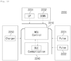
- FIG. 4 is a block diagram showing a stimulation signal module of a multichannel stimulation system for regenerating damaged corneal nerves according to an embodiment of the present invention
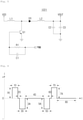
- FIG. 5 is a voltage control circuit diagram according to pressure recovery of an up button or a down button employed in a stimulation signal module of a multichannel stimulation system for regenerating damaged corneal nerves according to an embodiment of the present invention
- FIG. 6 is a view showing a current pulse signal provided by a stimulation signal module of a multichannel stimulation system for regenerating damaged corneal nerves according to an embodiment of the present invention.
- a multichannel unit 1100 of a multichannel stimulation system for regenerating damaged corneal nerves includes a first channel 1110 formed of a conductive material and attached between an area above the left eye and the left eyebrow to transfer a stimulation signal, a second channel 1120 formed of a conductive material and attached between an area above the right eye and the right eyebrow to transfer the stimulation signal, and a contactor 1130 formed between the first channel 1110 and the second channel 1120 in one piece to electrically contact with a stimulation signal module 1200.
- the first channel 1110, the second channel 1120 and the contactor 1130 may be formed of Ag, AgCl, Au, Pt or stainless steel.
- the stimulation signal module 1200 provides the first channel 1110 and the second channel 1120 with a current pulse signal as the stimulation signal and may be worn between the eyes and the nose of a person like wearing goggles as shown in FIG. 3 , and a magnet is arranged in each of the contactor 1130 of the multichannel unit 1100 and the stimulation signal module 1200, and when the contactor 1130 of the multichannel unit 1100 and the stimulation signal module 1200 approach each other within a predetermined range, the contactor 1130 of the multichannel unit 1100 and the stimulation signal module 1200 are self-aligned by the attraction force of the magnets.
- the stimulation signal module 1200 described above includes stimulation signal providing units 1221 and 1222 for generating a current pulse signal, a control unit 1210 for controlling the stimulation signal providing units 1221 and 1222, an up button 1231, a down button 1232, a communication unit 1240 communicating with the outside, and a charge unit 1250.
- the magnitude of the current pulse signal is increased in proportion to the number of times of applying the pressure to the up button 1231, and when a pressure is applied to the down button 1232 of the stimulation signal module 1200, the magnitude of the current pulse signal is decreased in inverse proportion to the number of times of applying the pressure to the down button 1232.
- the stimulation signal module 1200 controls to increase the magnitude of the current pulse signal by adjusting the number of pulses of a pulse width modulation (PWM) signal in proportion to the number of times of applying the pressure to the up button 1231, and when a pressure is applied to the down button 1232, the stimulation signal module 1200 controls to decrease the magnitude of the current pulse signal by adjusting the number of pulses of the pulse width modulation (PWM) signal in inverse proportion to the number of times of applying the pressure to the down button 1232.
- PWM pulse width modulation
- the boosted voltage is charged in the capacitors C2 and C3 in proportion to the number of pulse width modulation (PWM) signals, it may be controlled to increase the magnitude of the current pulse signal in proportion to the number of times of applying the pressure to the up button 1231 and to decrease the magnitude of the current pulse signal in inverse proportion to the number of times of applying the pressure to the down button 1232.
- PWM pulse width modulation
- the current pulse signal is configured of a positive current pulse signal during a first duration time 1D, a zero current signal during a second duration time 2D following the first duration time 1D, a negative current pulse signal during a third duration time 3D following the second duration time 2D, a zero current signal during a fourth duration time 4D following the third duration time 3D, a negative current pulse signal during a fifth duration time 5D following the fourth duration time 4D, a zero current signal during a sixth duration time 6D following the fifth duration time 5D, a positive current pulse signal during a seventh duration time 7D following the sixth duration time 6D, and a zero current signal during an eighth duration time 8D following the seventh duration time 7D.
- the fourth duration time 4D of the current pulse signal is 5 to 2,000 times of the second duration time 2D of the current pulse signal
- the eighth duration time 8D of the current pulse signal is 5 to 2,000 times of the sixth duration time 6D of the current pulse signal.
- the fourth duration time 4D of the current pulse signal is 25 to 10,000 ⁇ s
- the sixth duration time 6D of the current pulse signal is 5 ⁇ s
- the eighth duration time 8D of the current pulse signal is 25 to 10, 000 ⁇ s.
- magnitude 1A of the absolute value of the positive pulse current signal of the first duration time 1D of the current pulse signal is equal to magnitude 3A of the absolute value of the negative pulse current signal of the third duration time 3D of the current pulse signal
- magnitude 5A of the absolute value of the negative pulse current signal of the fifth duration time 5D of the current pulse signal is equal to magnitude 7A of the absolute value of the positive pulse current signal of the seventh duration time 7D of the current pulse signal.
- magnitude 1A of the absolute value of the positive pulse current signal of the first duration time 1D of the current pulse signal is 2 to 15 times of magnitude 3A of the absolute value of the negative pulse current signal of the third duration time 3D of the current pulse signal
- magnitude 5A of the absolute value of the negative pulse current signal of the fifth duration time 5D of the current pulse signal is 2 to 15 times of magnitude 7A of the absolute value of the positive pulse current signal of the seventh duration time 7D of the current pulse signal.
- the current pulse signal is configured to be in a charge-balanced state by configuring the absolute value of the positive pulse current signal of the first duration time 1D to be 2 to 15mA when the absolute value of the negative pulse current signal of the third duration time 3D is 1mA during the equal first duration time 1D and third duration time 3D, and the absolute value of the negative pulse current signal of the fifth duration time 5D to be 2 to 15mA when the absolute value of the positive pulse current signal of the seventh duration time 7D is 1mA during the equal fifth duration time 5D and seventh duration time 7D.
- the length of the first duration time 1D of the current pulse signal is equal to the length of the third duration time 3D of the current pulse signal
- the length of the fifth duration time 5D of the current pulse signal is equal to the length of the seventh duration time 7D of the current pulse signal.
- the length of the first duration time 1D of the current pulse signal is 2 to 15 times of the length of the third duration time 3D of the current pulse signal
- the length of the fifth duration time 5D of the current pulse signal is 2 to 15 times of the length of the seventh duration time 7D of the current pulse signal.
- the current pulse signal is configured to be in a charge-balanced state by configuring the first duration time 1D to be 20 to 300 ⁇ s when magnitude 1A of the absolute value of the positive pulse current signal of the first duration time 1D is equal to magnitude 3A of the absolute value of the negative pulse current signal of the third duration time 3D and the length of the third duration time 3D is 10 ⁇ s, and the fifth duration time 5D to be 20 to 300 ⁇ s when magnitude 5A of the absolute value of the negative pulse current signal of the fifth duration time 5D is equal to magnitude 7A of the absolute value of the positive pulse current signal of the seventh duration time 7D and the length of the seventh duration time 7D is 10 ⁇ s.
- the stimulation signal module 1200 provides the first channel 1110 with the current pulse signal of the first duration time 1D and the current pulse signal of the seventh duration time 7D, and provides the second channel 1120 with the current pulse signal of the third duration time 3D and the current pulse signal of the fifth duration time 5D.
- FIGS. 7 to 12 a multichannel stimulation system for regenerating damaged corneal nerves according to another embodiment of the present invention will be described with reference to FIGS. 7 to 12 .
- FIG. 7 is a view showing a multichannel unit of a multichannel stimulation system for regenerating damaged corneal nerves according to another embodiment of the present invention
- FIG. 8 is a view showing a state of attaching a multichannel unit of a multichannel stimulation system for regenerating damaged corneal nerves according to another embodiment of the present invention in an area close to the eyes of a person
- FIG. 9 is a view showing a state of attaching a multichannel unit and a stimulation signal module of a multichannel stimulation system for regenerating damaged corneal nerves according to another embodiment of the present invention in an area close to the eyes of a person
- FIG. 9 is a view showing a state of attaching a multichannel unit and a stimulation signal module of a multichannel stimulation system for regenerating damaged corneal nerves according to another embodiment of the present invention in an area close to the eyes of a person
- FIG. 10 is a block diagram showing a stimulation signal module of a multichannel stimulation system for regenerating damaged corneal nerves according to another embodiment of the present invention
- FIG. 11 is a voltage control circuit diagram according to pressure recovery of an up button or a down button employed in a stimulation signal module of a multichannel stimulation system for regenerating damaged corneal nerves according to another embodiment of the present invention
- FIG. 12 is a view showing a current pulse signal provided by a stimulation signal module of a multichannel stimulation system for regenerating damaged corneal nerves according to another embodiment of the present invention.
- a multichannel unit 2100 of a multichannel stimulation system for regenerating damaged corneal nerves includes a 11-th channel 2111 formed of a conductive material and attached above the left eyebrow to transfer a stimulation signal, a 12-th channel 2112 formed of a conductive material and attached below the left eye to transfer the stimulation signal, a 21-th channel 2121 formed of a conductive material and attached above the right eyebrow to transfer the stimulation signal, a 22-th channel 2122 formed of a conductive material and attached below the right eye to transfer the stimulation signal, and a contactor 2130 formed between the 11-th channel 2111 and the 21-th channel 2121 in one piece to electrically contact with the stimulation signal module.
- the 11-th channel 2111, the 12-th channel 2112, the 21-th channel 2121, the 22-th channel 2122 and the contactor 2130 may be formed of Ag, AgCl, Au, Pt or stainless steel.
- the stimulation signal module 2200 provides the 11-th channel 2111, the 12-th channel 2112, the 21-th channel 2121, and the 22-th channel 2122 with a current pulse signal as the stimulation signal and may be worn between the eyes and the nose of a person like wearing goggles as shown in FIG. 9 , and a magnet is arranged in each of the contactor 2130 of the multichannel unit 2100 and the stimulation signal module 2200, and when the contactor 2130 of the multichannel unit 2100 and the stimulation signal module 2200 approach each other within a predetermined range, the contactor 2130 of the multichannel unit 2100 and the stimulation signal module 2200 are self-aligned by the attraction force of the magnets.
- the stimulation signal module 2200 described above includes stimulation signal providing units 2221 and 2222 for generating a current pulse signal, a control unit 2210 for controlling the stimulation signal providing units 2221 and 2222, an up button 2231, a down button 2232, a communication unit 2240 communicating with the outside, and a charge unit 2250.
- the magnitude of the current pulse signal is increased in proportion to the number of times of applying the pressure to the up button 2231, and when a pressure is applied to the down button 2232 of the stimulation signal module 2200, the magnitude of the current pulse signal is decreased in inverse proportion to the number of times of applying the pressure to the down button 2232.
- the stimulation signal module 2200 controls to increase the magnitude of the current pulse signal by adjusting the number of pulses of a pulse width modulation (PWM) signal in proportion to the number of times of applying the pressure to the up button 2231, and when a pressure is applied to the down button 2232, the stimulation signal module 2200 controls to decrease the magnitude of the current pulse signal by adjusting the number of pulses of the pulse width modulation (PWM) signal in inverse proportion to the number of times of applying the pressure to the down button 2232.
- PWM pulse width modulation
- the boosted voltage is charged in the capacitors C2 and C3 in proportion to the number of pulse width modulation (PWM) signals, it may be controlled to increase the magnitude of the current pulse signal in proportion to the number of times of applying the pressure to the up button 2231 and to decrease the magnitude of the current pulse signal in inverse proportion to the number of times of applying the pressure to the down button 2232.
- PWM pulse width modulation
- the current pulse signal is configured of a positive current pulse signal during a first duration time 1D, a zero current signal during a second duration time 2D following the first duration time 1D, a negative current pulse signal during a third duration time 3D following the second duration time 2D, a zero current signal during a fourth duration time 4D following the third duration time 3D, a negative current pulse signal during a fifth duration time 5D following the fourth duration time 4D, a zero current signal during a sixth duration time 6D following the fifth duration time 5D, a positive current pulse signal during a seventh duration time 7D following the sixth duration time 6D, and a zero current signal during an eighth duration time 8D following the seventh duration time 7D.
- the fourth duration time 4D of the current pulse signal is 5 to 2,000 times of the second duration time 2D of the current pulse signal
- the eighth duration time 8D of the current pulse signal is 5 to 2,000 times of the sixth duration time 6D of the current pulse signal.
- the fourth duration time 4D of the current pulse signal is 25 to 10,000 ⁇ s
- the sixth duration time 6D of the current pulse signal is 5 ⁇ s
- the eighth duration time 8D of the current pulse signal is 25 to 10,000 ⁇ s.
- magnitude 1A of the absolute value of the positive pulse current signal of the first duration time 1D of the current pulse signal is equal to magnitude 3A of the absolute value of the negative pulse current signal of the third duration time 3D of the current pulse signal
- magnitude 5A of the absolute value of the negative pulse current signal of the fifth duration time 5D of the current pulse signal is equal to magnitude 7A of the absolute value of the positive pulse current signal of the seventh duration time 7D of the current pulse signal.
- magnitude 1A of the absolute value of the positive pulse current signal of the first duration time 1D of the current pulse signal is 2 to 15 times of magnitude 3A of the absolute value of the negative pulse current signal of the third duration time 3D of the current pulse signal
- magnitude 5A of the absolute value of the negative pulse current signal of the fifth duration time 5D of the current pulse signal is 2 to 15 times of magnitude 7A of the absolute value of the positive pulse current signal of the seventh duration time 7D of the current pulse signal.
- the current pulse signal is configured to be in a charge-balanced state by configuring the absolute value of the positive pulse current signal of the first duration time 1D to be 2 to 15mA when the absolute value of the negative pulse current signal of the third duration time 3D is 1mA during the equal first duration time 1D and third duration time 3D, and the absolute value of the negative pulse current signal of the fifth duration time 5D to be 2 to 15mA when the absolute value of the positive pulse current signal of the seventh duration time 7D is 1mA during the equal fifth duration time 5D and seventh duration time 7D.
- the length of the first duration time 1D of the current pulse signal is equal to the length of the third duration time 3D of the current pulse signal
- the length of the fifth duration time 5D of the current pulse signal is equal to the length of the seventh duration time 7D of the current pulse signal.
- the length of the first duration time 1D of the current pulse signal is 2 to 15 times of the length of the third duration time 3D of the current pulse signal
- the length of the fifth duration time 5D of the current pulse signal is 2 to 15 times of the length of the seventh duration time 7D of the current pulse signal.
- the current pulse signal is configured to be in a charge-balanced state by configuring the first duration time 1D to be 20 to 300 ⁇ s when magnitude 1A of the absolute value of the positive pulse current signal of the first duration time 1D is equal to magnitude 3A of the absolute value of the negative pulse current signal of the third duration time 3D and the length of the third duration time 3D is 10 ⁇ s, and the fifth duration time 5D to be 20 to 300 ⁇ s when magnitude 5A of the absolute value of the negative pulse current signal of the fifth duration time 5D is equal to magnitude 7A of the absolute value of the positive pulse current signal of the seventh duration time 7D and the length of the seventh duration time 7D is 10 ⁇ s.
- the stimulation signal module 2200 provides the 11-th channel 2111 with the current pulse signal of the first duration time 1D and the current pulse signal of the seventh duration time 7D, provides the 12-th channel 2112 with the current pulse signal of the third duration time 3D and the current pulse signal of the fifth duration time 5D, provides the 21-th channel 2121 with the current pulse signal of the first duration time 1D and the current pulse signal of the seventh duration time 7D, and provides the 22-th channel 2122 with the current pulse signal of the third duration time 3D and the current pulse signal of the fifth duration time 5D. That is, the stimulation signal module 2200 provides the same current pulse signal to the 11-th channel 2111 and the 21-th channel 2121, and provides the same current pulse signal to the 12-th channel 2112 and the 22-th channel 2122.
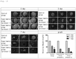
- FIG. 13 is a view showing pictures of measuring a degree of treatment of epithelial cells of a damaged cornea after 0 days, 3 days, and 7 days are elapsed while treating the damaged cornea using a multichannel stimulation system for regenerating damaged corneal nerves according to an embodiment of the present invention.
- a control group measures a damaged cornea of a patient, who has undergone vision correction surgery of cutting part of the cornea, after the patient has a normal treatment for the cornea (e.g., antibiotic administration), a first protocol experimental group measures the damaged cornea while treating the damaged cornea nerves with a current pulse signal of 20Hz using a multichannel stimulation system for regenerating damaged cornea nerves according to the embodiments of the present invention, in addition to the normal treatment (e.g., antibiotic administration) for the cornea of a patient who has undergone vision correction surgery of cutting part of the cornea, and a second protocol experimental group measures the damaged cornea while treating the damaged cornea nerves with a current pulse signal of 2Hz using a multichannel stimulation system for regenerating damaged cornea nerves according to the embodiments of the present invention, in addition to the normal treatment (e.g., antibiotic administration) for the cornea of the patient who has undergone vision correction surgery of cutting part of the cornea.
- a first protocol experimental group measures the damaged cornea while treating the damaged cornea nerves with a current pulse signal of 20Hz using a multi
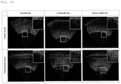
- FIG. 14 is a view showing pictures of measuring a degree of regeneration of nerve cells of a damaged cornea using a confocal microscope after 1 week, 2 weeks, and 4 weeks are elapsed while treating the damaged cornea using a multichannel stimulation system for regenerating damaged corneal nerves according to an embodiment of the present invention.
- a control group measures a degree of regeneration of the nerve cells of a damaged cornea of a patient, who has undergone vision correction surgery of cutting part of the cornea, after the patient has a normal treatment (e.g., antibiotic administration) for the cornea
- an experimental group measures a degree of regeneration of the nerve cells of the damaged cornea while treating the damaged cornea nerves using a multichannel stimulation system for regenerating damaged cornea nerves according to the embodiments of the present invention, in addition to the normal treatment (e.g., antibiotic administration) for the cornea of the patient who has undergone vision correction surgery of cutting part of the cornea.
- the nerve cells of the damaged cornea are regenerated more actively in the experimental groups, compared with the control group, as time is elapsed more.
- the multichannel stimulation system for regenerating damaged corneal nerves may effectively regenerate damaged corneal nerves by applying a current pulse signal as a stimulation signal through multiple channels attached in a plurality of areas close to the eyes.
Landscapes
- Health & Medical Sciences (AREA)
- Life Sciences & Earth Sciences (AREA)
- General Health & Medical Sciences (AREA)
- Veterinary Medicine (AREA)
- Engineering & Computer Science (AREA)
- Biomedical Technology (AREA)
- Public Health (AREA)
- Animal Behavior & Ethology (AREA)
- Nuclear Medicine, Radiotherapy & Molecular Imaging (AREA)
- Radiology & Medical Imaging (AREA)
- Ophthalmology & Optometry (AREA)
- Heart & Thoracic Surgery (AREA)
- Biophysics (AREA)
- Vascular Medicine (AREA)
- Neurology (AREA)
- Neurosurgery (AREA)
- Electrotherapy Devices (AREA)
Applications Claiming Priority (2)
| Application Number | Priority Date | Filing Date | Title |
|---|---|---|---|
| KR1020190044505A KR102064546B1 (ko) | 2019-04-16 | 2019-04-16 | 손상된 각막 신경 재생을 위한 멀티 채널 자극 시스템 |
| PCT/KR2020/000469 WO2020213819A1 (fr) | 2019-04-16 | 2020-01-10 | Système de stimulation à canaux multiples permettant la régénération de nerfs cornéens lésés |
Publications (4)
| Publication Number | Publication Date |
|---|---|
| EP3957357A1 true EP3957357A1 (fr) | 2022-02-23 |
| EP3957357A4 EP3957357A4 (fr) | 2022-07-06 |
| EP3957357B1 EP3957357B1 (fr) | 2024-05-22 |
| EP3957357C0 EP3957357C0 (fr) | 2024-05-22 |
Family
ID=69154829
Family Applications (1)
| Application Number | Title | Priority Date | Filing Date |
|---|---|---|---|
| EP20791493.8A Active EP3957357B1 (fr) | 2019-04-16 | 2020-01-10 | Système de stimulation à canaux multiples permettant la régénération de nerfs cornéens lésés |
Country Status (10)
| Country | Link |
|---|---|
| US (1) | US10695566B1 (fr) |
| EP (1) | EP3957357B1 (fr) |
| JP (1) | JP7245929B2 (fr) |
| KR (1) | KR102064546B1 (fr) |
| CN (1) | CN113677393B (fr) |
| AU (1) | AU2020257753B2 (fr) |
| BR (1) | BR112021020621A2 (fr) |
| CA (1) | CA3135938C (fr) |
| GB (1) | GB2596694B (fr) |
| WO (1) | WO2020213819A1 (fr) |
Families Citing this family (12)
| Publication number | Priority date | Publication date | Assignee | Title |
|---|---|---|---|---|
| US20180001107A1 (en) | 2016-07-01 | 2018-01-04 | Btl Holdings Limited | Aesthetic method of biological structure treatment by magnetic field |
| US10695575B1 (en) | 2016-05-10 | 2020-06-30 | Btl Medical Technologies S.R.O. | Aesthetic method of biological structure treatment by magnetic field |
| US11464993B2 (en) | 2016-05-03 | 2022-10-11 | Btl Healthcare Technologies A.S. | Device including RF source of energy and vacuum system |
| US12558146B2 (en) | 2019-04-11 | 2026-02-24 | Btl Medical Solutions A.S. | Methods and devices for aesthetic treatment of biological structures by radiofrequency and magnetic energy |
| KR102064546B1 (ko) * | 2019-04-16 | 2020-01-09 | 주식회사 뉴아인 | 손상된 각막 신경 재생을 위한 멀티 채널 자극 시스템 |
| US12611545B2 (en) | 2020-05-04 | 2026-04-28 | Btl Healthcare Technologies A.S. | Device and method for unattended treatment of a patient |
| JP2023515722A (ja) | 2020-05-04 | 2023-04-13 | ビーティーエル ヘルスケア テクノロジーズ エー.エス. | 患者の非アテンド式治療のためのデバイスおよび方法 |
| US11878167B2 (en) | 2020-05-04 | 2024-01-23 | Btl Healthcare Technologies A.S. | Device and method for unattended treatment of a patient |
| KR102409445B1 (ko) * | 2020-06-02 | 2022-06-14 | 주식회사 뉴아인 | 안면 신경 자극 시스템 |
| KR20220122174A (ko) * | 2021-02-26 | 2022-09-02 | 사회복지법인 삼성생명공익재단 | 신경세포 재생 및 면역질환 억제를 위한 장치 |
| KR20230126977A (ko) * | 2022-02-24 | 2023-08-31 | 사회복지법인 삼성생명공익재단 | 각막조직 재생을 위한 미세전류 자극장치 |
| US20260097226A1 (en) | 2024-10-08 | 2026-04-09 | Btl Medical Solutions A.S. | Devices and methods for application of a magnetic field to the nervous system |
Family Cites Families (17)
| Publication number | Priority date | Publication date | Assignee | Title |
|---|---|---|---|---|
| JPH07142872A (ja) * | 1993-11-12 | 1995-06-02 | Sanyo Electric Co Ltd | 電子機器 |
| KR100590796B1 (ko) * | 2004-07-09 | 2006-06-19 | 주식회사 대창 | 복합식 토출관을 구비한 얼음 디스펜서 |
| US20070244523A1 (en) * | 2006-04-13 | 2007-10-18 | Case Western Reserve University | System and method for selective retinal stimulation |
| US20130066283A1 (en) * | 2009-10-23 | 2013-03-14 | Nexisvision, Inc. | Corneal Denervation for Treatment of Ocular Pain |
| CA2796885A1 (fr) * | 2010-04-19 | 2011-10-27 | Boston Scientific Neuromodulation Corporation | Systeme de neurostimulation avec des moyens pour l'activation d'une transition energetique incrementielle |
| US9199080B2 (en) * | 2011-09-12 | 2015-12-01 | Okuvision Gmbh | Method for treating an eye |
| US10293161B2 (en) * | 2013-06-29 | 2019-05-21 | Thync Global, Inc. | Apparatuses and methods for transdermal electrical stimulation of nerves to modify or induce a cognitive state |
| EP3013414B1 (fr) * | 2013-06-29 | 2018-09-19 | Cerevast Medical Inc. | Dispositifs de stimulation électrique transdermique et procédés permettant de modifier ou d'induire un état cognitif |
| WO2016138025A2 (fr) * | 2015-02-23 | 2016-09-01 | Tissuetech, Inc. | Appareils et méthodes de traitement de maladies et de troubles ophtalmiques |
| KR102427652B1 (ko) * | 2015-03-30 | 2022-08-01 | 세팔리 테크놀로지 에스피알엘 | 삼차 신경의 경피 전기 자극을 위한 장치 |
| JP6763510B2 (ja) * | 2015-06-10 | 2020-09-30 | 国立大学法人千葉大学 | 網膜に電気刺激を与えるための装置および方法 |
| AU2016323117B2 (en) * | 2015-09-15 | 2019-10-31 | I-Lumen Scientific, Inc. | Apparatus and method for ocular microcurrent stimulation therapy |
| US11007367B2 (en) | 2016-03-16 | 2021-05-18 | Nova Oculus Canada Manufacturing Ulc | Microcurrent device for the treatment of visual disease |
| EP3481492B1 (fr) * | 2016-07-08 | 2024-03-13 | Cala Health, Inc. | Systèmes pour stimuler n nerfs avec exactement n électrodes et électrodes sèches améliorées |
| TWI686223B (zh) * | 2017-05-02 | 2020-03-01 | 加拿大商諾瓦眼部加拿大製造無限責任公司 | 用於視覺疾病治療之直接電刺激供給系統 |
| KR102064547B1 (ko) * | 2019-04-16 | 2020-01-09 | 주식회사 뉴아인 | 손상된 각막 신경 재생을 위한 멀티 채널 자극 시스템의 사용 방법 |
| KR102064546B1 (ko) * | 2019-04-16 | 2020-01-09 | 주식회사 뉴아인 | 손상된 각막 신경 재생을 위한 멀티 채널 자극 시스템 |
-
2019
- 2019-04-16 KR KR1020190044505A patent/KR102064546B1/ko active Active
-
2020
- 2020-01-10 GB GB2114033.0A patent/GB2596694B/en not_active Expired - Fee Related
- 2020-01-10 AU AU2020257753A patent/AU2020257753B2/en active Active
- 2020-01-10 CN CN202080028584.7A patent/CN113677393B/zh active Active
- 2020-01-10 JP JP2021561646A patent/JP7245929B2/ja active Active
- 2020-01-10 WO PCT/KR2020/000469 patent/WO2020213819A1/fr not_active Ceased
- 2020-01-10 BR BR112021020621A patent/BR112021020621A2/pt not_active Application Discontinuation
- 2020-01-10 EP EP20791493.8A patent/EP3957357B1/fr active Active
- 2020-01-10 CA CA3135938A patent/CA3135938C/fr active Active
- 2020-01-14 US US16/742,140 patent/US10695566B1/en active Active
Also Published As
| Publication number | Publication date |
|---|---|
| CA3135938A1 (fr) | 2020-10-22 |
| AU2020257753B2 (en) | 2022-11-17 |
| JP7245929B2 (ja) | 2023-03-24 |
| US10695566B1 (en) | 2020-06-30 |
| GB2596694A (en) | 2022-01-05 |
| CN113677393A (zh) | 2021-11-19 |
| EP3957357B1 (fr) | 2024-05-22 |
| GB202114033D0 (en) | 2021-11-17 |
| EP3957357C0 (fr) | 2024-05-22 |
| EP3957357A4 (fr) | 2022-07-06 |
| WO2020213819A1 (fr) | 2020-10-22 |
| GB2596694B (en) | 2022-10-05 |
| CA3135938C (fr) | 2023-10-17 |
| JP2022539940A (ja) | 2022-09-14 |
| AU2020257753A1 (en) | 2021-10-28 |
| CN113677393B (zh) | 2023-11-03 |
| KR102064546B1 (ko) | 2020-01-09 |
| BR112021020621A2 (pt) | 2021-12-07 |
Similar Documents
| Publication | Publication Date | Title |
|---|---|---|
| EP3957357B1 (fr) | Système de stimulation à canaux multiples permettant la régénération de nerfs cornéens lésés | |
| US10786667B1 (en) | Method of using multichannel stimulation system for regenerating damaged corneal nerves | |
| CA2776693C (fr) | Dispositifs, systemes et procedes pour le traitement de troubles et de d'affections neurologiques | |
| CN103167850B (zh) | 利用离子透入角膜传输核黄素治疗圆锥角膜的装置 | |
| US20070150027A1 (en) | Non-invasive device and method for electrical stimulation of neural tissue | |
| WO2018203132A1 (fr) | Système d'administration de stimulation électrique directe pour le traitement d'une maladie visuelle | |
| KR102654067B1 (ko) | 신경성장인자 발현정도 증가 및 이식 각막 생존율 증가를 위한 장치 | |
| US20260077197A1 (en) | Systems and methods for ocular microstimulation therapy | |
| Mielacher et al. | Once daily versus twice daily theta-burst stimulation in the treatment of major depression disorder | |
| Phillips et al. | Reward circuitry-targeted transcranial direct current stimulation impacts underlying reward circuitry function and affect: A promising intervention for bipolar disorder | |
| AU2015264876B2 (en) | Devices, Systems and Methods for Treatment of Neuropsychiatric Disorders | |
| CN1126519C (zh) | 一种电生理屈光不正调节器 | |
| WO2025088825A1 (fr) | Dispositif et fixation pour stimulation électrique transcutanée de seconde division et/ou de troisième division de nerf trijumeau |
Legal Events
| Date | Code | Title | Description |
|---|---|---|---|
| STAA | Information on the status of an ep patent application or granted ep patent |
Free format text: STATUS: THE INTERNATIONAL PUBLICATION HAS BEEN MADE |
|
| PUAI | Public reference made under article 153(3) epc to a published international application that has entered the european phase |
Free format text: ORIGINAL CODE: 0009012 |
|
| STAA | Information on the status of an ep patent application or granted ep patent |
Free format text: STATUS: REQUEST FOR EXAMINATION WAS MADE |
|
| 17P | Request for examination filed |
Effective date: 20211008 |
|
| AK | Designated contracting states |
Kind code of ref document: A1 Designated state(s): AL AT BE BG CH CY CZ DE DK EE ES FI FR GB GR HR HU IE IS IT LI LT LU LV MC MK MT NL NO PL PT RO RS SE SI SK SM TR |
|
| A4 | Supplementary search report drawn up and despatched |
Effective date: 20220608 |
|
| RIC1 | Information provided on ipc code assigned before grant |
Ipc: A61F 9/00 20060101ALI20220601BHEP Ipc: A61N 1/04 20060101ALI20220601BHEP Ipc: A61N 1/36 20060101AFI20220601BHEP |
|
| DAV | Request for validation of the european patent (deleted) | ||
| DAX | Request for extension of the european patent (deleted) | ||
| GRAP | Despatch of communication of intention to grant a patent |
Free format text: ORIGINAL CODE: EPIDOSNIGR1 |
|
| STAA | Information on the status of an ep patent application or granted ep patent |
Free format text: STATUS: GRANT OF PATENT IS INTENDED |
|
| INTG | Intention to grant announced |
Effective date: 20231221 |
|
| GRAS | Grant fee paid |
Free format text: ORIGINAL CODE: EPIDOSNIGR3 |
|
| GRAA | (expected) grant |
Free format text: ORIGINAL CODE: 0009210 |
|
| STAA | Information on the status of an ep patent application or granted ep patent |
Free format text: STATUS: THE PATENT HAS BEEN GRANTED |
|
| AK | Designated contracting states |
Kind code of ref document: B1 Designated state(s): AL AT BE BG CH CY CZ DE DK EE ES FI FR GB GR HR HU IE IS IT LI LT LU LV MC MK MT NL NO PL PT RO RS SE SI SK SM TR |
|
| REG | Reference to a national code |
Ref country code: GB Ref legal event code: FG4D |
|
| REG | Reference to a national code |
Ref country code: CH Ref legal event code: EP |
|
| REG | Reference to a national code |
Ref country code: DE Ref legal event code: R096 Ref document number: 602020031355 Country of ref document: DE |
|
| REG | Reference to a national code |
Ref country code: IE Ref legal event code: FG4D |
|
| U01 | Request for unitary effect filed |
Effective date: 20240620 |
|
| REG | Reference to a national code |
Ref country code: LT Ref legal event code: MG9D |
|
| REG | Reference to a national code |
Ref country code: NL Ref legal event code: MP Effective date: 20240522 |
|
| U07 | Unitary effect registered |
Designated state(s): AT BE BG DE DK EE FI FR IT LT LU LV MT NL PT RO SE SI Effective date: 20240902 |
|
| PG25 | Lapsed in a contracting state [announced via postgrant information from national office to epo] |
Ref country code: IS Free format text: LAPSE BECAUSE OF FAILURE TO SUBMIT A TRANSLATION OF THE DESCRIPTION OR TO PAY THE FEE WITHIN THE PRESCRIBED TIME-LIMIT Effective date: 20240922 |
|
| PG25 | Lapsed in a contracting state [announced via postgrant information from national office to epo] |
Ref country code: HR Free format text: LAPSE BECAUSE OF FAILURE TO SUBMIT A TRANSLATION OF THE DESCRIPTION OR TO PAY THE FEE WITHIN THE PRESCRIBED TIME-LIMIT Effective date: 20240522 |
|
| PG25 | Lapsed in a contracting state [announced via postgrant information from national office to epo] |
Ref country code: GR Free format text: LAPSE BECAUSE OF FAILURE TO SUBMIT A TRANSLATION OF THE DESCRIPTION OR TO PAY THE FEE WITHIN THE PRESCRIBED TIME-LIMIT Effective date: 20240823 |
|
| PG25 | Lapsed in a contracting state [announced via postgrant information from national office to epo] |
Ref country code: ES Free format text: LAPSE BECAUSE OF FAILURE TO SUBMIT A TRANSLATION OF THE DESCRIPTION OR TO PAY THE FEE WITHIN THE PRESCRIBED TIME-LIMIT Effective date: 20240522 |
|
| PG25 | Lapsed in a contracting state [announced via postgrant information from national office to epo] |
Ref country code: PL Free format text: LAPSE BECAUSE OF FAILURE TO SUBMIT A TRANSLATION OF THE DESCRIPTION OR TO PAY THE FEE WITHIN THE PRESCRIBED TIME-LIMIT Effective date: 20240522 |
|
| PG25 | Lapsed in a contracting state [announced via postgrant information from national office to epo] |
Ref country code: PL Free format text: LAPSE BECAUSE OF FAILURE TO SUBMIT A TRANSLATION OF THE DESCRIPTION OR TO PAY THE FEE WITHIN THE PRESCRIBED TIME-LIMIT Effective date: 20240522 Ref country code: NO Free format text: LAPSE BECAUSE OF FAILURE TO SUBMIT A TRANSLATION OF THE DESCRIPTION OR TO PAY THE FEE WITHIN THE PRESCRIBED TIME-LIMIT Effective date: 20240822 Ref country code: IS Free format text: LAPSE BECAUSE OF FAILURE TO SUBMIT A TRANSLATION OF THE DESCRIPTION OR TO PAY THE FEE WITHIN THE PRESCRIBED TIME-LIMIT Effective date: 20240922 Ref country code: HR Free format text: LAPSE BECAUSE OF FAILURE TO SUBMIT A TRANSLATION OF THE DESCRIPTION OR TO PAY THE FEE WITHIN THE PRESCRIBED TIME-LIMIT Effective date: 20240522 Ref country code: GR Free format text: LAPSE BECAUSE OF FAILURE TO SUBMIT A TRANSLATION OF THE DESCRIPTION OR TO PAY THE FEE WITHIN THE PRESCRIBED TIME-LIMIT Effective date: 20240823 Ref country code: ES Free format text: LAPSE BECAUSE OF FAILURE TO SUBMIT A TRANSLATION OF THE DESCRIPTION OR TO PAY THE FEE WITHIN THE PRESCRIBED TIME-LIMIT Effective date: 20240522 Ref country code: RS Free format text: LAPSE BECAUSE OF FAILURE TO SUBMIT A TRANSLATION OF THE DESCRIPTION OR TO PAY THE FEE WITHIN THE PRESCRIBED TIME-LIMIT Effective date: 20240822 |
|
| PG25 | Lapsed in a contracting state [announced via postgrant information from national office to epo] |
Ref country code: CZ Free format text: LAPSE BECAUSE OF FAILURE TO SUBMIT A TRANSLATION OF THE DESCRIPTION OR TO PAY THE FEE WITHIN THE PRESCRIBED TIME-LIMIT Effective date: 20240522 |
|
| PG25 | Lapsed in a contracting state [announced via postgrant information from national office to epo] |
Ref country code: SK Free format text: LAPSE BECAUSE OF FAILURE TO SUBMIT A TRANSLATION OF THE DESCRIPTION OR TO PAY THE FEE WITHIN THE PRESCRIBED TIME-LIMIT Effective date: 20240522 |
|
| PG25 | Lapsed in a contracting state [announced via postgrant information from national office to epo] |
Ref country code: SK Free format text: LAPSE BECAUSE OF FAILURE TO SUBMIT A TRANSLATION OF THE DESCRIPTION OR TO PAY THE FEE WITHIN THE PRESCRIBED TIME-LIMIT Effective date: 20240522 Ref country code: CZ Free format text: LAPSE BECAUSE OF FAILURE TO SUBMIT A TRANSLATION OF THE DESCRIPTION OR TO PAY THE FEE WITHIN THE PRESCRIBED TIME-LIMIT Effective date: 20240522 |
|
| REG | Reference to a national code |
Ref country code: DE Ref legal event code: R097 Ref document number: 602020031355 Country of ref document: DE |
|
| PLBE | No opposition filed within time limit |
Free format text: ORIGINAL CODE: 0009261 |
|
| STAA | Information on the status of an ep patent application or granted ep patent |
Free format text: STATUS: NO OPPOSITION FILED WITHIN TIME LIMIT |
|
| 26N | No opposition filed |
Effective date: 20250225 |
|
| REG | Reference to a national code |
Ref country code: CH Ref legal event code: PL |
|
| PG25 | Lapsed in a contracting state [announced via postgrant information from national office to epo] |
Ref country code: MC Free format text: LAPSE BECAUSE OF FAILURE TO SUBMIT A TRANSLATION OF THE DESCRIPTION OR TO PAY THE FEE WITHIN THE PRESCRIBED TIME-LIMIT Effective date: 20240522 |
|
| U90 | Renewal fees not paid: noting of loss of rights |
Free format text: RENEWAL FEE NOT PAID FOR YEAR 06 Effective date: 20250818 |
|
| GBPC | Gb: european patent ceased through non-payment of renewal fee |
Effective date: 20250110 |
|
| PG25 | Lapsed in a contracting state [announced via postgrant information from national office to epo] |
Ref country code: GB Free format text: LAPSE BECAUSE OF NON-PAYMENT OF DUE FEES Effective date: 20250110 |
|
| PG25 | Lapsed in a contracting state [announced via postgrant information from national office to epo] |
Ref country code: CH Free format text: LAPSE BECAUSE OF NON-PAYMENT OF DUE FEES Effective date: 20250131 |
|
| U93 | Unitary patent lapsed |
Free format text: RENEWAL FEE NOT PAID Effective date: 20250131 |
|
| PG25 | Lapsed in a contracting state [announced via postgrant information from national office to epo] |
Ref country code: IE Free format text: LAPSE BECAUSE OF NON-PAYMENT OF DUE FEES Effective date: 20250110 |